DORAN BOOSTER Tyre Pressure Monitoring System User Manual
DORAN MANUFACTURING, LLC. Tyre Pressure Monitoring System Users Manual
DORAN >
Users Manual
SMART BOOSTER User Manual
The smart booster is used to transmit the signal of transmitter and
magnified it. Then transmit it to the monitor. The smart booster can
match the different monitors automatically. In order to ensure good
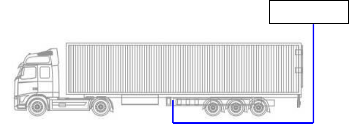
communication, please choose a suitable location for it on the beam of
the vehicle bottom. The location should be near the middle of the vehicle
bottom.
1. Fix the booster onto rubber plate with 4 screws with diameter of 6mm.
2. Fix rubber plate and triangle together with 2 screws with diameter of
6mm.
3. Drain 2 holes with diameter of 6mm on the beam of the vehicle bottom
according to the installation holes in triangle and then fix the booster
with the screws. As shown below:
Smart Booster
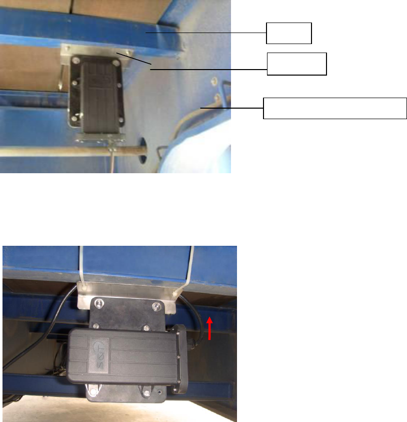
Method1. Perpendicular to the beam of the vehicle bottom
Mothod2. Parallel to the beam of the vehicle bottom
Note: The side with power wire face up.
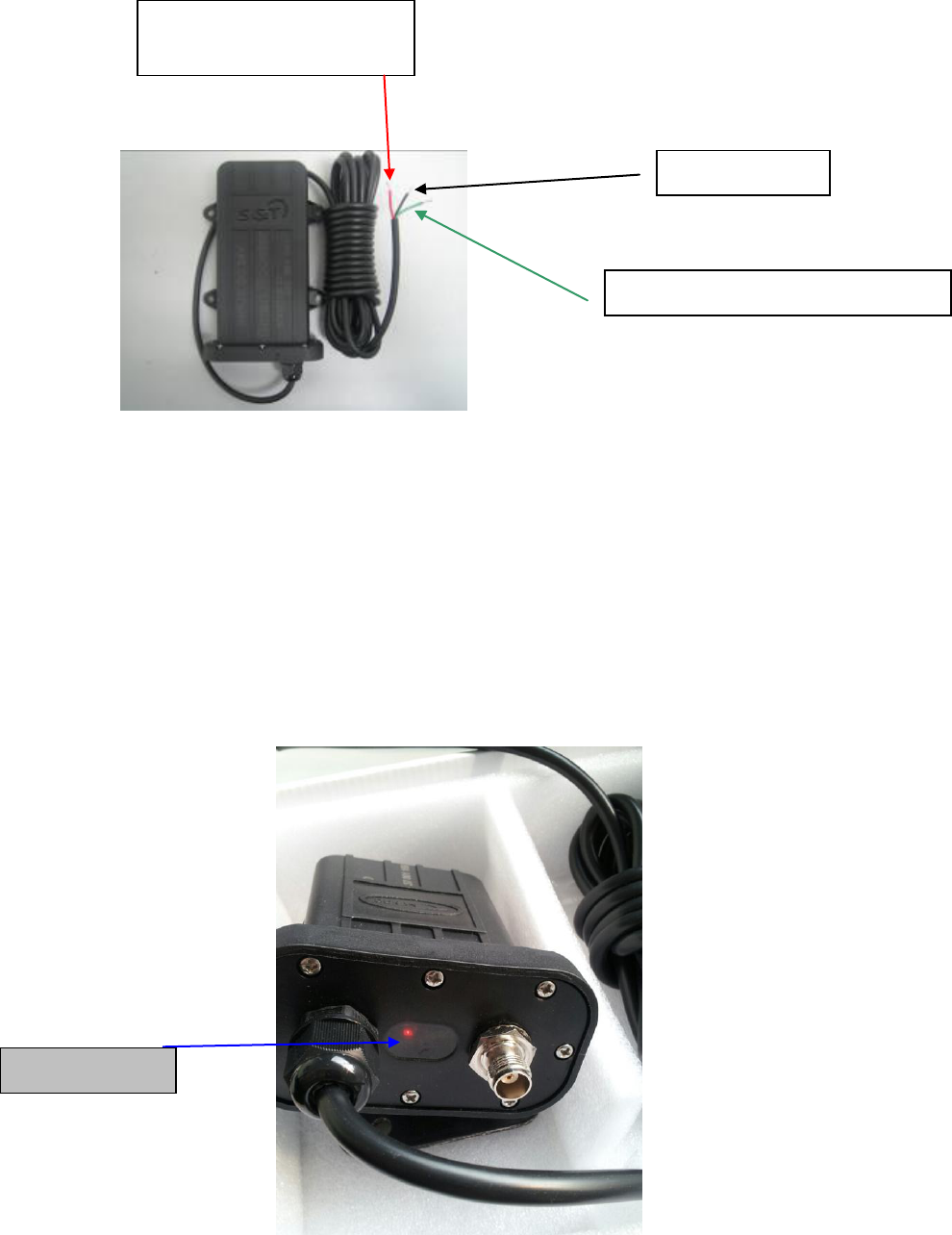
4. The smart booster with 3 power wires. Connect brown power wire with
positive of vehicle’s continuous power supply, blue wire with the
positive of ignition switch, the bule wire have 12V power supply only
when the ignition switch is powered. Connect the yellow and green
wire to ground. Then fix the power wires with nylon strips.
beam
triangle
Power wire of smart booster
5. Indicator light explanation
Three red LED lights in the transparent window of smart booster, from
left to right: power indicator, transmitting indicator and receiving
indicator light. As shown below:
Connect ground
Connect positive of 12V/24V
contiuous power supply
Connect positive of ignition switch
power indicator
IMPORTANT NOTES:
1. Smart booster should be installed in the free space properly.
2. If there isn’t a proper position in the middle bottom of vehicle, user
can install it in the side of vehicle.
3. In order to ensure good communication of smart booster, please don't
conjoint the smart booster to the metal directly.
4. The power wires should be fixed with nylon strips to prevent them
being frazzling and short circuit.
5. Ensure the input voltage is accordant with smart booster voltage.
Connect the power wires according to marked positive and negative
wire.
6. Please connect a 2A waterproof fuse at the position of smart booster
connect the continuous power supply of vehicle to ensure the safety of
circuitry.
Specifications:
Modulation Type: FSK
Mid-frequency: 434.1 MHz
Receiving Sensitivity: -105 dBm
Input Voltage: 12V / 24V
Operating Temperature: -40℃~+85℃
Storage Temperature: -30℃~75℃
Federal Communications Commission (FCC) Interference Statement
This device complies with Part 15 of the FCC Rules. Operation is subject to the following
two conditions:
(1) This device may not cause harmful interference, and (2) this device must accept any
interference received, including interference that may cause undesired operation.
FCC Caution: Any changes or modifications not expressly approved by the party
responsible for compliance could void the user’s authority to operate this equipment.
RF exposure warning
This equipment complies with FCC radiation exposure limits set forth for an uncontrolled
environment.