DQ Technology M405R3 ADSL2+ Broadband Gateway User Manual KD318RI
DQ Technology, Inc. ADSL2+ Broadband Gateway KD318RI
Users Manual

FOUR-PORT ADSL ROUTER
M405 ADSL Router
User Manual

ADSL ROUTER USER MANUAL
NOTICE
This document contains proprietary information protected by copyright, and this Manual
and all the accompanying hardware, software, and documentation are copyrighted. All
rights are reserved. No part of this document may be photocopied or reproduced by
mechanical, electronic, or other means in any form.
The manufacturer does not warrant that the hardware will work properly in all environments
and applications, and makes no warranty or representation, either expressed or implied,
with respect to the quality, performance, merchantability, or fitness for a particular purpose
of the software or documentation. The manufacturer reserves the right to make changes to
the hardware, software, and documentation without obligation to notify any person or
organization of the revision or change.
All brand and product names are the trademarks of their respective owners.
© Copyright 2012
All rights reserved.

Content
1 OVERVIEW .............................................................................................................................................1
1.1 FEATURES .....................................................................................................................................1
1.2 PACKET CONTENTS ......................................................................................................................2
1.3 SYSTEM REQUIREMENTS ..............................................................................................................3
1.4 FACTORY DEFAULTS .....................................................................................................................3
1.5 WARNINGS AND CAUTIONS ...........................................................................................................3
2 HARDWARE DESCRIPTION ...............................................................................................................4
3 HARDWARE INSTALLATION .............................................................................................................5
4 SOFTWARE INSTALLATION ..............................................................................................................5
5 PC CONFIGURATION GUIDE .............................................................................................................6
5.1 LOCAL PC CONFIGURATION .........................................................................................................6
5.2 ACCESS THE PROGRAM ................................................................................................................7
5.3 INTERNET ACCESS CONFIGURATION..............................................................................................7
APPENDIX FREQUENT ASKED QUESTIONS .................................................................................16

ADSL ROUTER USER MANUAL
1
1 Overview
Thank you for using this Asymmetric Digital Subscriber Line (ADSL) router. With the
asymmetric technology, this device runs over standard copper phone lines. In addition,
ADSL allows you to have both voice and data services in use simultaneously all over one
phone line. It is an ideal solution for the small and medium size business environment.
This ADSL router provides a 10/100BaseT interface for Ethernet connection and an USB
interface for USB connection at the user end. Computers can simultaneously connect to
the router either via its USB, Switch or both ports to share its high-speed Internet access.
You can connect to its Switch port regardless of the operating system you are using, or
connect to its USB port to allow easy installation to a USB equipped computer. It receives
adaptive rates up to 24Mbps and transmits 1Mbps upstream.
1.1 Features
1.1.1 ADSL Compliance
ANSI T1.413 issue 2
Downstream: Up to 24Mbps.
Max upstream speed: 3.5Mbps (With AnnexM enabled)
Rate Adaptive at 32 Kbps steps
Interoperable with all major DSLAM equipment
TR-069 compliant with ACS
1.1.2 Standards & Protocols Conformance
ITU G.994.1(G.hs) G.992.1(G.DMT) G.992.2(G.LITE)
ITU G.992.3(G.DMT.BIS)
ITU G.992.5
T1.413
EoA (PPPoE, IPoE, and Bridge)
PPPoA
IPoA
1.1.3 Operating System Support
WINDOWS 98/98 SE/ME/2000/XP/VISTA/7
Macintosh
LINUX

ADSL ROUTER USER MANUAL
2
1.1.4 ATM Capabilities
ATM Connection
VPI Range: 0-255
VCI Range: 32-65535
AESA (E.164, DCC, ICD)
PVC Support
UNI 3.0 & 3.1 Signaling
Support AAL 5
1.1.5 Management Support
Web Based GUI
Upgrade or update via FTP/HTTP
Command Line Interface via Telnet
Diagnostic Test
Firmware upgrade-able for future feature enhancement
1.1.6 Environmental
Operating humidity: 10%-90% non-condensing
Non-operating storage humidity: 5%-95% non-condensing
1.2 Packet Contents
The packet contents are as the following:
ADSL Router x 1
External Splitter x 1
Power Adapter x 1
Telephone Line x 1
Ethernet Cable x 1
USB Cable x 1
CD x 1

ADSL ROUTER USER MANUAL
3
1.3 System Requirements
Before using this ADSL router, verify that you meet the following
requirements:
Subscription for ADSL service. Your ADSL service provider should
provide you with at least one valid IP address (static assignment or
dynamic assignment via dial-up connection).
One or more computers, each contains an Ethernet 10/100M Base-T
network interface card (NIC).
A hub or switch, if you are connecting the device to more than four
computers.
For system configuration using the supplied web-based program: A web
browser such as Internet Explorer v5.0 or later, or Netscape v4.7 or
later.
1.4 Factory Defaults
The device is configured with the following factory defaults:
IP Address: 192.168.1.1
Subnet Mask: 255.255.255.0
VPI/VCI: According to local information
1.5 Warnings and Cautions
Never install telephone wiring during storm. Avoid using a telephone
during an electrical storm. There might be a risk of electric shock from
lightening.
Do not install telephone jacks in wet locations and never use the
product near water.
To prevent dangerous overloading of the power circuit, be careful about
the designed maximum power load ratings. Not to follow the rating
guideline could result in a dangerous situation.
Please note that telephone line on ADSL router must adopt the primary
line that directly outputs from junction box. Do not connect ADSL router
to extension phone. In addition, if your house developer divides a
telephone line to multi sockets inside the wall of house, please only use
the telephone that has connected with the splitter of ADSL router when
you access the Internet. Under the above condition, if you also install
telephone with anti-cheat-dial device, please pull out this kind of
telephone, otherwise ADSL router may occur frequently off-line.
ADSL ROUTER USER MANUAL
4
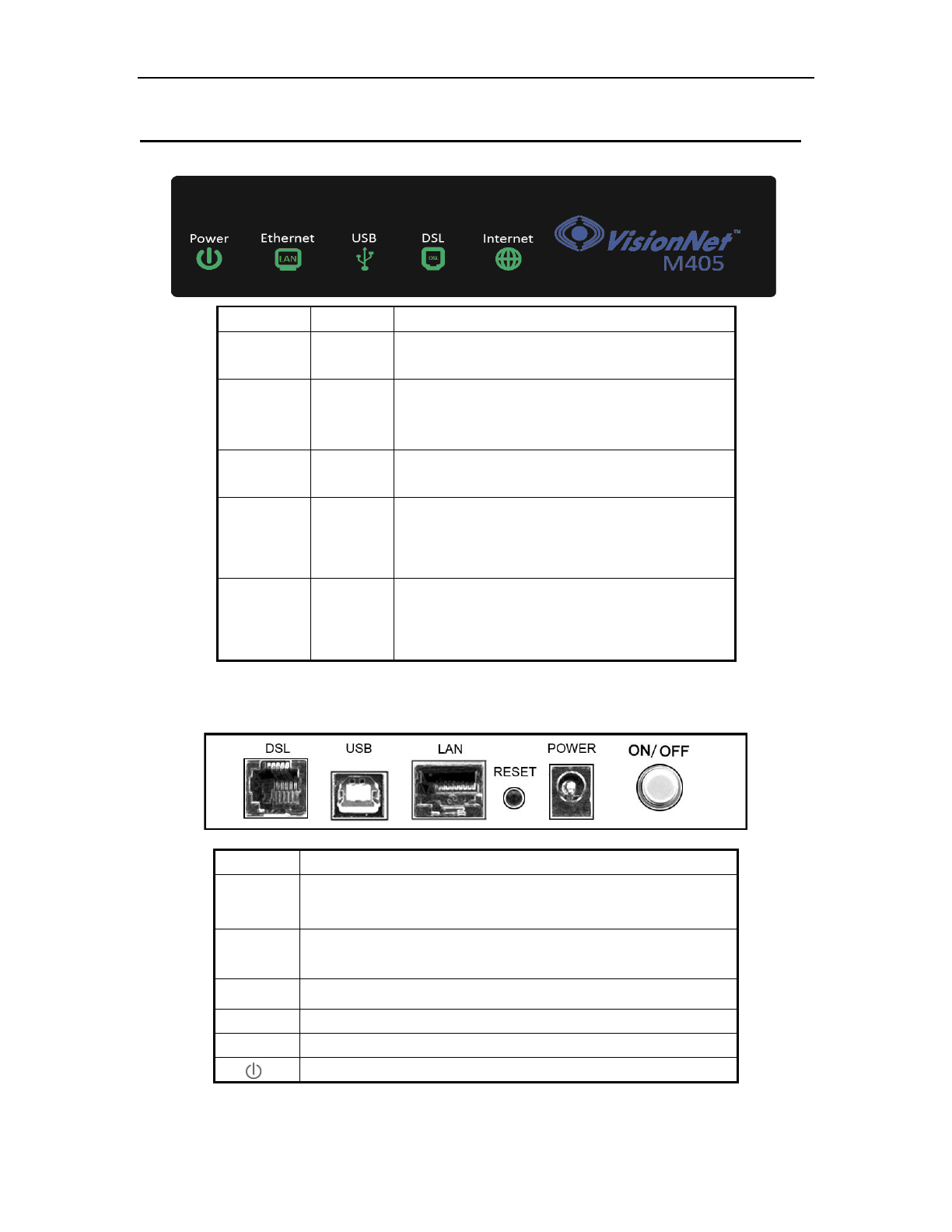
2 Hardware Description
Front Panel
Rear Panel
Port Function
DSL Connects the device to an ADSL telephone jack or splitter using a RJ-11
telephone cable
LAN Connects the device to your PC's Ethernet port, or to the uplink port
on your hub/switch, using a RJ-45 cable
USB Connects the device to your PC's USB port
Reset System reset or reset to factory defaults.
POWER Connects to the supplied power adapter
Switches the unit on and off
LED Color Function
PWR Green On: Power
Off: No power or system boot failed
DSL Green
On: ADSL link established and active
Blinking: ADSL is trying to establish a connection
Off: No ADSL link
ACT Green Blinking: ADSL data activity occurs.
Off: No ADSL data is being sent or received.
LAN Green
On: LAN link established and active
Blinking: ADSL data activity occurs.
Off: No LAN link.
USB Green On: USB link established and active
Off: No USB link

ADSL ROUTER USER MANUAL
5
3 Hardware Installation
This Hardware Installation describes how to connect ADSL router to your computer,
LAN and the Internet. This Installation assumes you have subscribed to an ISP for
ADSL service and only covers the basic configurations to be applied to residential
or corporate networks.
Hardware Connection
1. Using a telephone line to connect the DSL port of ADSL router to the MODEM
port of the splitter, and using another telephone line to connect your telephone
to the PHONE port of the splitter, then connect the wall phone jack to the LINE
port of the splitter.
The splitter comes with three connectors as below:
LINE: Connects to a wall phone jack (RJ-11 jack)
MODEM: Connects to the DSL jack of ADSL router
PHONE: Connects to a telephone set
2. Using an Ethernet Cable to connect the LAN port of the ADSL router to your
LAN or a PC with network card installed.
3. Connect the power cable to the POWER connector on ADSL router, then plug
in the power adapter to the power outlet, and then press the on-off button.
Notes: Without the splitter and certain situation, transient noise from telephone
can interfere with the operation of the ADSL router, and the ADSL router
may introduce noise to the telephone line. To prevent this from happening,
a small external splitter must be connected to each telephone.
4 Software Installation
This chapter shows you how to install the router’s USB drivers when PC connects to
the router via its USB port.
1. Insert the rectangular end of a USB cable into the USB port of your PC.
2. Insert the square end of the USB cable into the USB port of the Router.
3. Power on the router and then a dialog box of “ A new hardware is found” is
displayed on the screen.
4. Press “Next” button, the system then search for hardware driving program.
Choose the soft driver in the “assigned position” and press “next”, the system
will automatically install the driving program recorded on the soft disk into the
system.

ADSL ROUTER USER MANUAL
6
5 PC Configuration Guide
5.1 Local PC Configuration
5.1.1 Windows 95, 98, ME, XP
1. In the Windows task bar, click the “Start” button, point to “Settings”, and then
click “Control Panel”.
2. Double-click the “Network” icon.
3. On the “Configuration” tab, select the TCP/IP network associated with your
network card and then click “Properties”.
4. In the “TCP/IP Properties” dialog box, click the “IP Address” tab. Set the IP
address as 192.168.1.x (x can be a decimal number from 2 to 254.) like
192.168.1.2, and the subnet mask as 255.255.255.0.
5. On the “Gateway” tab, set a new gateway as 192.168.1.1, and then click
“Add”.
6. Configure the “DNS” tab if necessary. For information on the IP address of
the DNS server, please consult with your ISP.
7. Click “OK” twice to confirm and save your changes.
8. You will be prompted to restart Windows. Click “Yes”.
5.1.2 Windows 2000
1. In the Windows task bar, click the “Start” button, point to “Settings”, and then
click “Control Panel”.
2. Double-click the “Network and Dial-up Connections” icon.
3. In the “Network and Dial-up Connections” window, right-click the “Local Area
Connection” icon, and then select “Properties”.
4. Highlight “Internet Protocol (TCP/IP)”, and then click “Properties”.
5. In the “Internet Protocol (TCP/IP) Properties” dialog box, set the IP address
as 192.168.1.x (x can be a decimal number from 2 to 254.), and the subnet
mask as 255.255.255.0 and the default gateway as 192.168.1.1. Then click
“OK”.
6. Configure the “DNS” tab if necessary. For information on the IP address of
the DNS server, please consult with your ISP.
7. Click “OK” twice to confirm and save your changes.
ADSL ROUTER USER MANUAL
7
5.2 Access the program
After configuring the IP Address of you computer, powering on the ADSL Router, and
launching a web browser, such as Internet Explorer, use http://192.168.1.1 to log on to
the setting pages.
Attention: the username and password are both lowercase.
5.3 Internet Access Configuration
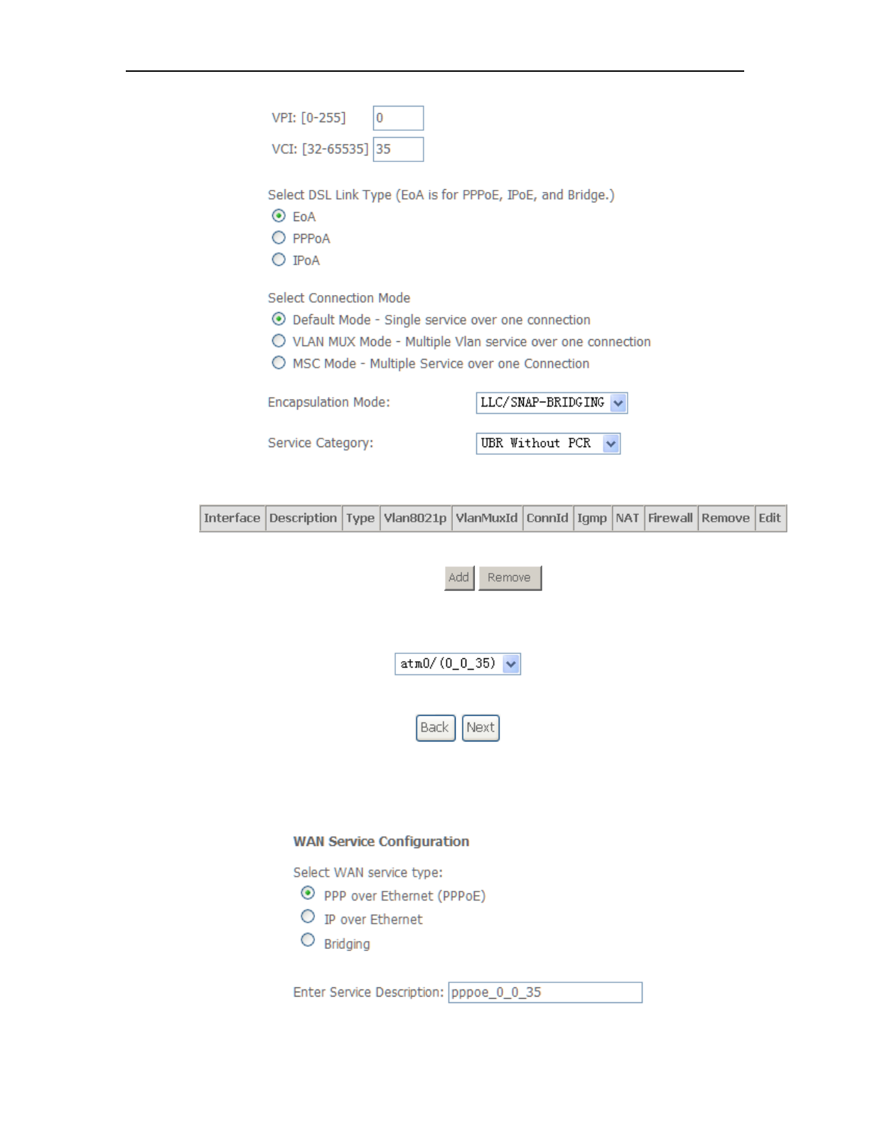
5.3.1 ADSL Mode Setup
From home page, you can find Advanced Setup option on the left router
configuration page.
1. From Layer2 Interface, click ATM Interface. you can set it up according to the
following steps. You Choose Add, or Remove to configure DSL ATM interfaces.
2. Click Add to configure PVC identifier, select connection mode according to your
local occasion. After the configuration, you need to click Apply/Save.
Click OK
Enter username ‘admin’
and password ‘adslroot’
ADSL ROUTER USER MANUAL
8
3. Click WAN Service from the left menu.
4. Click Add to select a layer 2 interface for this service and then click Next.
5. Choose WAN service type, just choose PPPoE for example here. You can enter
your own service description here if you want and then click Next.
ADSL ROUTER USER MANUAL
9
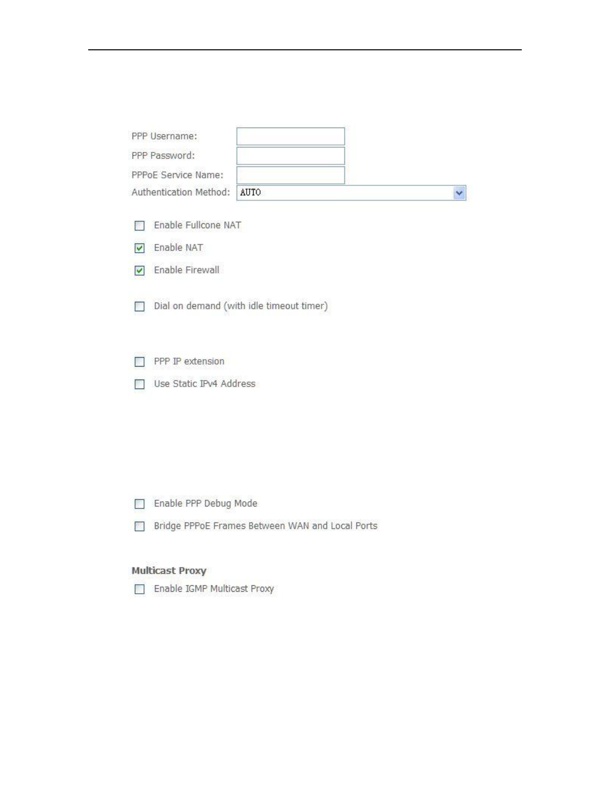
6. Input PPP Username & PPP Password and then click Next. The user interface
allows a maximum of 256 characters in the user name and a maximum of 32
characters in the password.
PPPoE service name can be blank unless your Internet Service Provider gives you a
value to enter.
Authentication method is default to Auto. It is recommended that you leave the
Authentication method in Auto, however, you may select PAP or CHAP if necessary.
The default value for MTU (Maximum Transmission Unit) is 1500 for PPPoA and 1492 for
PPPoE. Do not change these values unless your ISP asks you to.

ADSL ROUTER USER MANUAL
10
Enable FullCone NAT, all requests from the same private IP address and port are
mapped to the same public source IP address and port. Someone on the Internet only
needs to know the mapping scheme in order to send packets to a device behind the
ADSL router.
The gateway can be configured to disconnect if there is no activity for a specific period of
time by selecting the Dial on demand check box and entering the Inactivity timeout.
The entered value must be between 1 minute and 4320 minutes.
The PPP IP Extension is a special feature deployed by some service providers. Unless
your service provider specifically requires this setup, do not select it. If you need to select
it, the PPP IP Extension supports the following conditions:
It allows only one computer on the LAN.
The public IP address assigned by the remote using the PPP/IPCP
protocol is actually not used on the WAN PPP interface. Instead, it is
forwarded to the computer's LAN interface through DHCP. Only one
system on the LAN can be connected to the remote, since the DHCP
server within the ADSL gateway has only a single IP address to assign
to a LAN device.
NAPT and firewall are disabled when this option is selected.
The gateway becomes the default gateway and DNS server to the
computer through DHCP using the LAN interface IP address.
The gateway extends the IP subnet at the remote service provider to the
LAN computer. That is, the PC becomes a host belonging to the same
IP subnet.
The ADSL gateway bridges the IP packets between WAN and LAN ports,
unless the packet is addressed to the gateway's LAN IP address.
Use static IPv4 IP address, If the ISP gave you a static IP address, select this option
and enter it in the IP address field.
Bridge PPPoE Frames Between WAN and Local Ports is available when you do not
use PPP IP extension. If you enable this function, LAN hosts can use PPPoE client
software on their computers to connect to the ISP. Each host can have a separate
account and a public WAN IP address.
ADSL ROUTER USER MANUAL
11
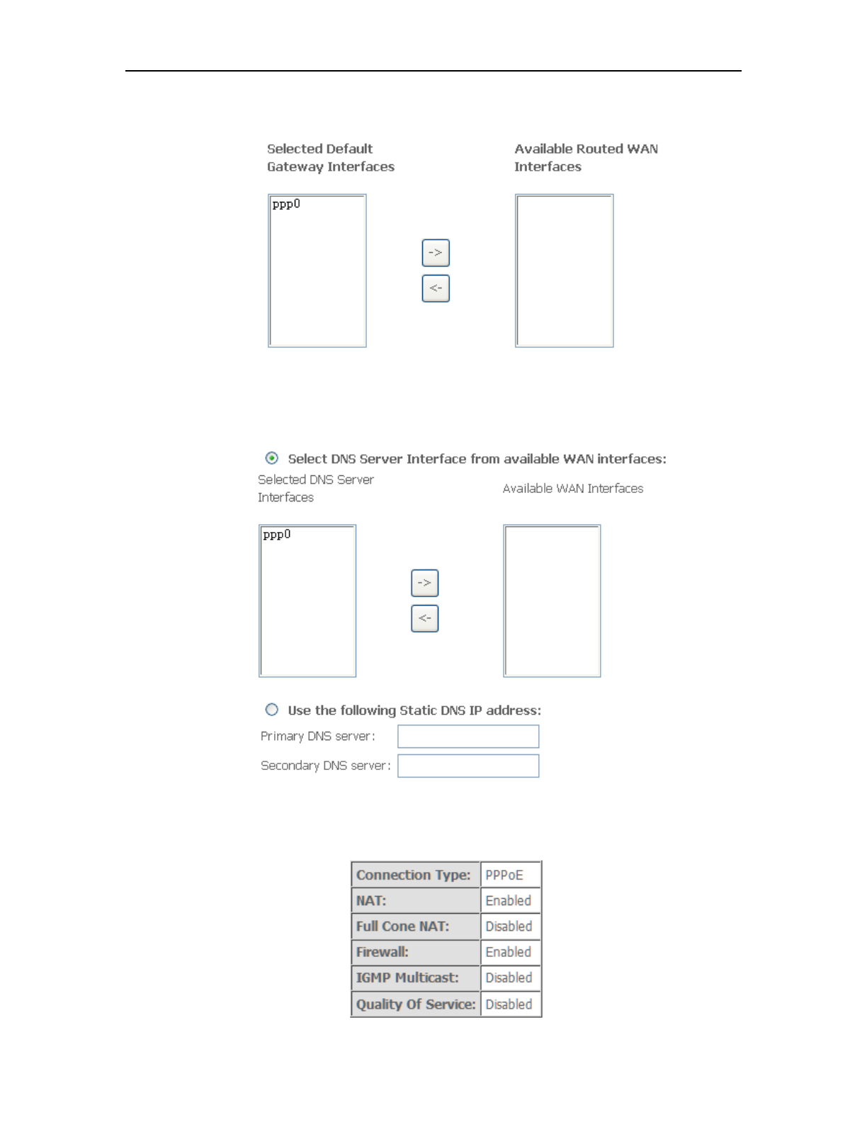
7. Select a preferred wan interface as the system default gateway.
8. Get DNS server information from the selected WAN interface or enter static DNS
server IP addresses. If only a single PVC with IPoA or static MER protocol is
configured, you must enter static DNS server IP addresses.
9. Make sure that the settings below match the settings provided by your ISP. Click on
the Apply/Save button to save your configurations.
ADSL ROUTER USER MANUAL
12
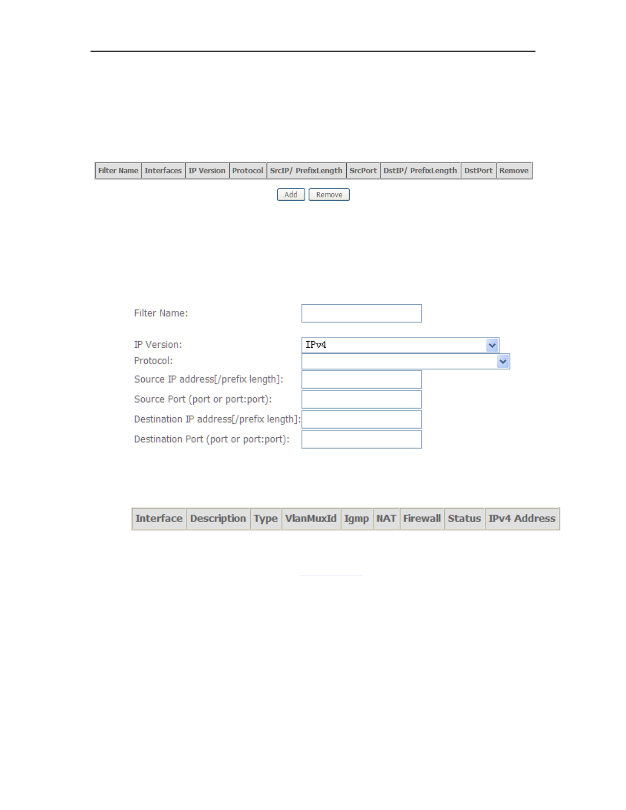
5.3.2 Remote Access
When the firewall is enabled on a WAN or LAN interface, all incoming IP traffic is
BLOCKED. However, some IP traffic can be ACCEPTED by setting up filters.
1. Select Advanced Setup=>Security=>IP Filtering=>Incoming and Choose Add or
Remove to configure incoming IP filters.
2. Click Add to add rules. If you want to do remote ping test, please select protocol
as ICMP; If you want to do Http or Telnet test, please select protocol as TCP/UDP.
If you want only Http remote access, you can set destination port as 80; If you
want only Telnet remote access, you can set destination port as 23; If you want
both, you can set destination port as blank.
3. Click Apply/Save and select Device Info=>WAN. You can see that the IP
address is x.x.x.x.
4. Now you can access the ADSL router remotely using username support and
password support. You can input http://x.x.x.x/ for Http and input telnet x.x.x.x for
Telnet.
ADSL ROUTER USER MANUAL
13
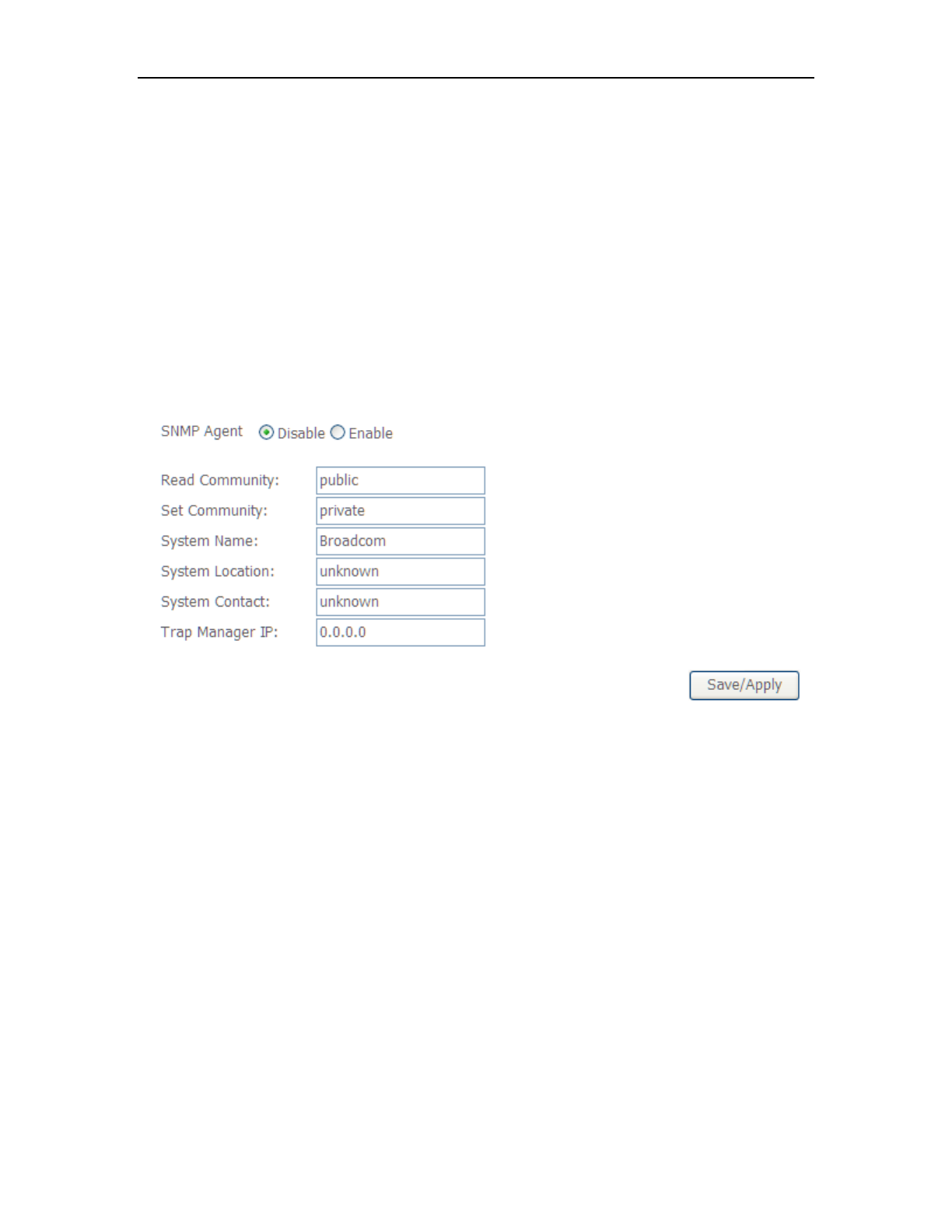
5.3.3 SNMP Agent
SNMP (Simple Network Management Protocol) has been widely applied in the
computer networks currently, which is used for ensuring the transmission of the
management information between any two nodes. In this way, network
administrators can easily search and modify the information on any node on the
network. Meanwhile, they can locate faults promptly and implement the fault
diagnosis, capacity planning and report generating.
An SNMP Agent is an application running on the Router that performs the
operational role of receiving and processing SNMP messages, sending responses to
the SNMP manager, and sending traps when an event occurs. So a Router contains
SNMP "agent" software can be monitored and/or controlled by SNMP Manager using
SNMP messages.
SNMP Agent: You can select the checkbox to disable or enable the function.
Note:
SNMP Community string provides a simple method of authentication between the
Router (SNMP Agent) and a remote network manager (SNMP Manager). You can
specify the community string as the password to authenticate the management
station to the Router.
Read Community: This field allows you to specify the SNMP Community string
which provides read-only access to the Router that the community is only permitted
to read the device configuration. The default value is “public”.
Set Community: This field allows you to specify the SNMP Community string
which provides read and write access to the Router that the community has the
authority to read and change the device configuration. The default value is “public”.
ADSL ROUTER USER MANUAL
14
System Name: Enter alphanumeric string to specify an SNMP community string
name. Your Router (SNMP agents) will expose management data on the managed
systems as this "system name".
System Location: The person to notify when problems occur.
System contact: The location of the person that is identified as the system
contact.
Trap Manager IP: Enter the IP address of the SNMP Manager,where the SNMP
Agent forwards trap notifications.
Select the desired values and click Save/Apply to configure the SNMP options.
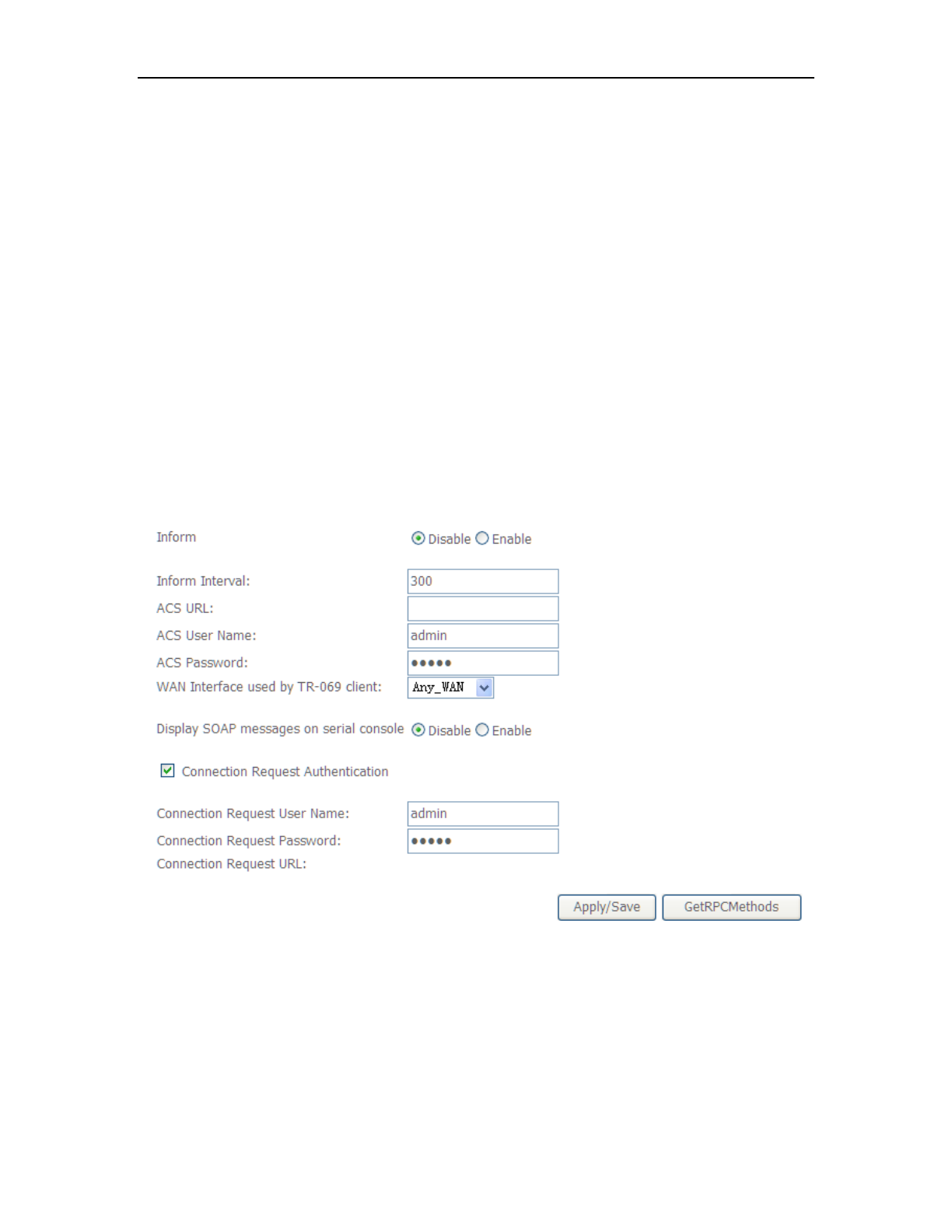
5.3.4 TR069 Client
WAN Management Protocol (TR-069) allows a Auto-Configuration Server (ACS) to
perform auto-configuration, provision, collection, and diagnostics to this device.
Inform: Whether or not the CPE must periodically send CPE information to Server using
the Inform method call.
Inform Interval: The duration in seconds of the interval for which the CPE MUST attempt
to connect with the ACS and call the Inform method if Inform is enabled.
ACS URL: URL for the CPE to connect to the ACS using the CPE WAN Management
Protocol.

ADSL ROUTER USER MANUAL
15
ACS User Name: Username used to authenticate an ACS making a Connection Request
to the CPE.
ACS Password: Password used to authenticate an ACS making a Connection Request
to the CPE. When read, this parameter returns an empty string, regardless of the actual
value.
WAN Interface used by TR-069 client: Remember to choose the interface of PVC used
for TR069
Connection Request User Name: Username used to authenticate the CPE when
making a connection to the ACS using the CPE WAN Management Protocol. This
username is used only for authentication of the CPE.
Connection Request Password: Password used to authenticate the CPE when making
a connection to the ACS using the CPE WAN Management Protocol. This password is
used only for authentication of the CPE.
GetRPCMethods: Used by a CPE or ACS to discover the set of methods supported by
the ACS or CPE it is in communicate with.

ADSL ROUTER USER MANUAL
16
Appendix Frequent Asked Questions
Q: None of the LEDs are on when you power on the ADSL router?
A: Please make sure what you use is the power adaptor attached with the ADSL router
package,and check the connection between the AC power and ADSL router.
Q: DSL LED does not turn on after connect telephone line?
A: Please make sure what you use is the standard telephone line (as attached with the
package), make sure the line is connected correctly and check whether there is poor
contact at each interface. Wait for 30 seconds to allow the ADSL router establishes
connection with you ADSL operator.
Q: DSL LED is in the circulation of slow-flashing and fast-flashing after connecting
telephone line?
A: This situation means the ADSL router is in the status of failing to establish connection
with Central Office. Please check carefully and confirm whether the ADSL router has
been installed correctly.
Q: LAN LED does not turn on after connect Ethernet cable?
A: Please make sure Ethernet cable is connected hub/PC and ADSL router correctly.
Then please make sure the PC/hub have been power on.
Please make sure that you use parallel network cable to connect UpLink port of hub,
or use parallel network cable to connect PC. If connect normal port of hub (not
UpLink port), you must use cross-cable. Please make sure that your network cables
meet the networking requirements above.
Q: PC cannot access the Internet?
A: First check whether PC can ping the interface Ethernet IP address of this product
successfully (default value is 192.168.1.1) by using ping application. If ping
application fails, please check the connection of Ethernet cable and check whether
the states of LEDs are in gear.
If the PC uses private IP address that is set manually (non-registered legal IP
address), please check:
1. Whether IP address of the PC gateway is legal IP address. Otherwise please
use the right gateway, or set the PC to Obtain an IP address automatically.
2. Please confirm the validity of DNS server appointed to the PC with ADSL
operator. Otherwise please use the right DNS, or set the PC to Obtain an IP
address automatically.
3. Please make sure you have set the NAT rules and convert private IP address to
legal IP address. IP address range of the PC that you specify should meet the
setting range in NAT rules.
Central Office equipment may have problem.
Q: PC cannot browse Internet web page?
A: Please make sure DNS server appointed to the PC is correct. You can use ping
application program to test whether the PC can connect to the DNS server of the
ADSL operator.

ADSL ROUTER USER MANUAL
17
Q: Initialization of the PVC connection failed?
A: Be sure that cable is connected properly from the DSL port to the wall jack. The DSL
LED on the front panel of the ADSL router should be on. Check that your VPI, VCI,
type of encapsulation and type of multiplexing setting are the same as what you
collected from your service provider, Re-configure ADSL router and reboot it. If you
still can not work it out, you may need to verify these variables with the service
provider.
If the cause is not given above, please contact your local service provider

ADSL ROUTER USER MANUAL
18
FCC Caution:
Any Changes or modifications not expressly approved by the party responsible for compliance could void the user's authority to
This device complies with part 15 of the FCC Rules. Operation is subject to the following two conditions:(1) This device may
operate the equipment.
not cause harmful interference, and (2) this device must accept any interference received, including interference that may
cause undesired operation.
IMPORTANT NOTE:
FCC Radiation Exposure Statement:
This equipment complies with FCC radiation exposure limits set forth for an uncontrolled environment .This equipment should be
This transmitter must not be co-located or operating in conjunction with any other antenna or transmitter.
installed and operated with minimum distance 20cm between the radiator& your body.
Note: This equipment has been tested and found to comply with the limits for a class B digital device,pursuant to part 15 .
of the FCC rules.This limits are designed to provide reasonable protection against harnful interenference in a residential
installation . this equipment generates ,uses and can radiate radio frequency energy and ,if not installed and used in
accordance with the instructionsmay case harmful interference to radio communication.However, there is no grantee
will not occur in a particular installation.If this equipment doses cause harmful interference to radio or television reception ,
which can be determined by turning the equipment off and on , the user is encourage to try to correct the interference
by one or more of the following mersures:
-Reorient or relocate the receiving antenna.
-Increase the separation between the equipment and receiver.
-Connect the equipment into an outlet on a circuit different from that to which the receiver is connected.
-Consult the dealer or an experienced radio/TV technician for help
Customer Information
1.This equipment complies with Part 68 of the FCC rules and the requirements adopted by the ACTA. On the bottom
of this equipment is a label that contains, among other information, a product identifier in the format US:AAAEQ##
TXXXX. If requested, this number must be provided to the telephone company.
2. A plug and jack used to connect this equipment to the premises wiring and telephone network must comply with the
applicable FCC Part 68 rules and requirements adopted by the ACTA. A compliant telephone cord and modular plug
is provided with this product. It is designed to be connected to a compatible modular jack that is also compliant.
See installation instructions for details.
3.If this equipment [US: DQ1DL01BM405R3] causes harm to the telephone network, the telephone company will notify
you in advance that temporary discontinuance of service may be required. But if advance notice isn't practical, the telephone
company will notify the customer as soon as possible. Also, you will be advised of your right to file a complaint with the FCC if
you believe it is necessary
4.The telephone company may make changes in its facilities, equipment, operations or procedures that could affect the operati
on
of the equipment. If this happens the telephone company will provide advance notice in order for you to make necessary
modifications to maintain uninterrupted service.
may r
5.
pho
5.If trouble is experienced with this equipment [US: DQ1DL01BM405R3], for repair or warranty information, Service can be
U.S. Agent Company name:
facilitated through our office at:
Address:
Tel:
If the equipment is causing harm to the telephone network, the telephone company may request that you disconnect
the equipment until the problem is resolved.
DQ Technology, Inc.
5111 Johnson Drive.Pleasanton, CA 94588, USA
+1 925 730 3940
6.Please follow instructions for repairing if any (e.g. battery replacement section); otherwise do not alternate or repair any parts
of device except specified. For repair procedures, follow the instructions outlined under the limited warranty.
7.Connection to party line service is subject to state tariffs. Contact the state public utility commission, public service commission
or corporation commission for information.
8.If your home has specially wired alarm equipment connected to the telephone line, ensure the installation of this [M405R3]does
not disable your alarm equipment.If you have questions about what will disable alam equipment ,consult your telephone
9.If the telephone company requests information on what equipment is connected to their lines, inform them of
a)The ringer equivalence number[ 0.1B]
b)The USOC jack required [RJ11C]
c)Facility Interface Codes ("FIC") [METALLIC]
d)Service Order Codes ("SOC") [9.0Y]
e)The FCC Registration Numbe [US:DQ1DL01BM405R3]
10.The REN is used to determine the number of devices that may be connected to a telephone line.
Excessive RENs on a telephone line may result in the devices not ringing in response to an incoming call. In most but not all areas,
the sum of RENs should not exceed five (5.0). To be certain of the number of devices that may be connected to a line, as determined by
the total RENs, contact the local telephone company. The REN for this product is part of the product identifier that has the format
US:AAAEQ##TXXXX. The digits represented by ## are the REN without a decimal point. For this product the FCC Registration number
is [US: DQ1DL01BM405R3] indicates the REN would be 0.1.
company or a qualified installer