DRS Tactical Systems 622ANH Intel Centrino Advanced-N 6200 User Manual Manual
DRS Tactical Systems, Inc. Intel Centrino Advanced-N 6200 Manual
UserManual.wiki
>
DRS Tactical Systems
>
622ANH User Manual
>
Manual
Contents
1.
Manual
2.
Users Manual 1 of 2
3.
Users Manual 2 of 2
Manual
Navigation menu
Upload a User Manual
Namespaces
Wiki Guide
HTML
PDF
Info
Views
User Manual
Discussion / Help
Navigation
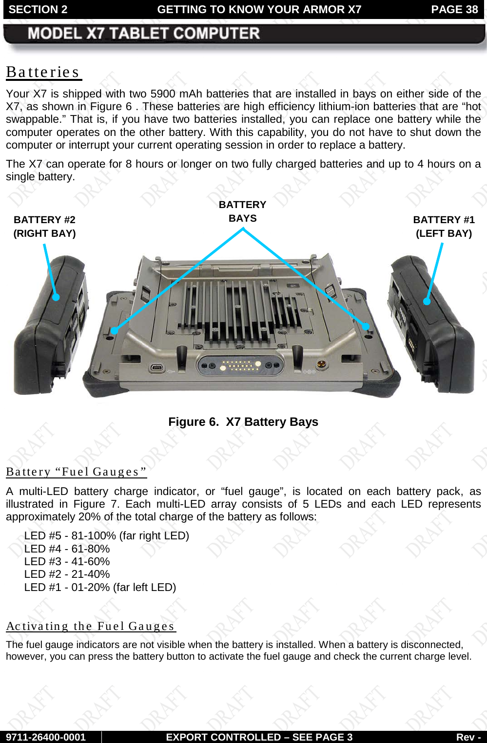
![FRONT MATTER PAGE 9 9711-26400-0001 EXPORT CONTROLLED – SEE PAGE 3 Rev - CAUTION! DO NOT use this unit in classified areas unsuitable for its safety ratings. NE PAS UTILISER CETTE UNITÉ EN ZONES AINSI CLASSÉES IMPROPRES À SA COTE DE SÉCURITÉ CAUTION! When using IEEE 802.11a wireless LAN [in Canada], this product is restricted to indoor use due to its operation in the 5.15- to 5.25-GHz frequency range. Industry Canada requires this product to be used indoors for the frequency range of 5.15 GHz to 5.25 GHz to reduce the potential for harmful interference to co-channel mobile satellite systems. High power radar is allocated as the primary user of the 5.25- to 5.35-GHz and 5.65 to 5.85-GHz bands. These radar stations can cause interference with and/or damage to this device.](https://usermanual.wiki/DRS-Tactical-Systems/622ANH.Manual/User-Guide-1371205-Page-9.png)
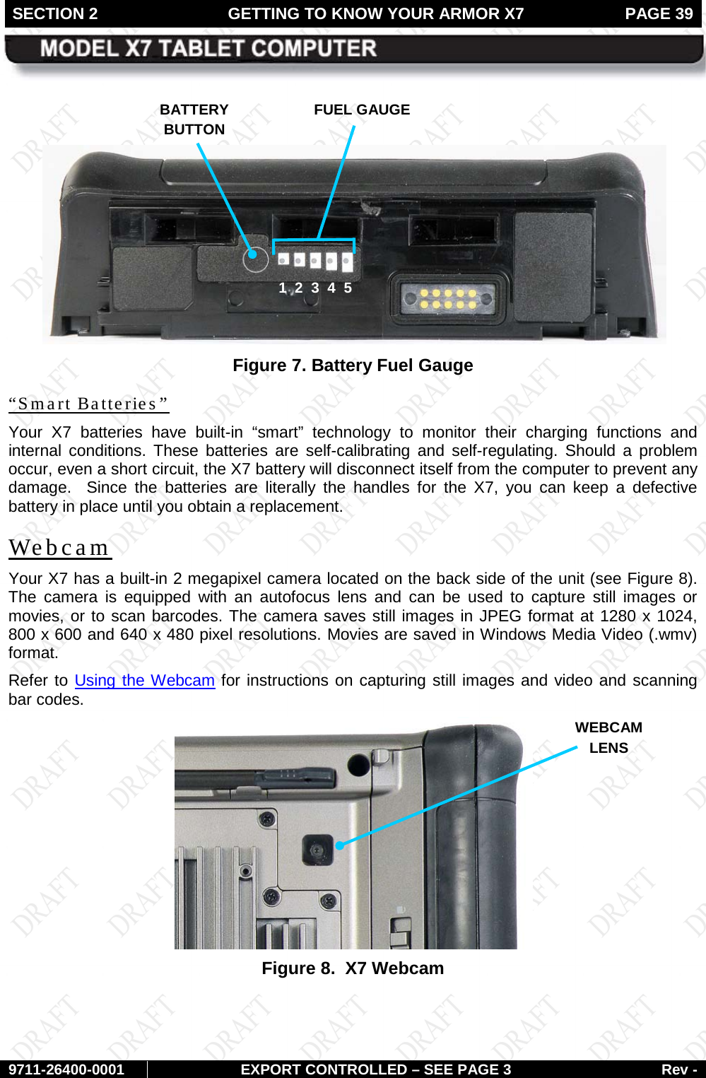

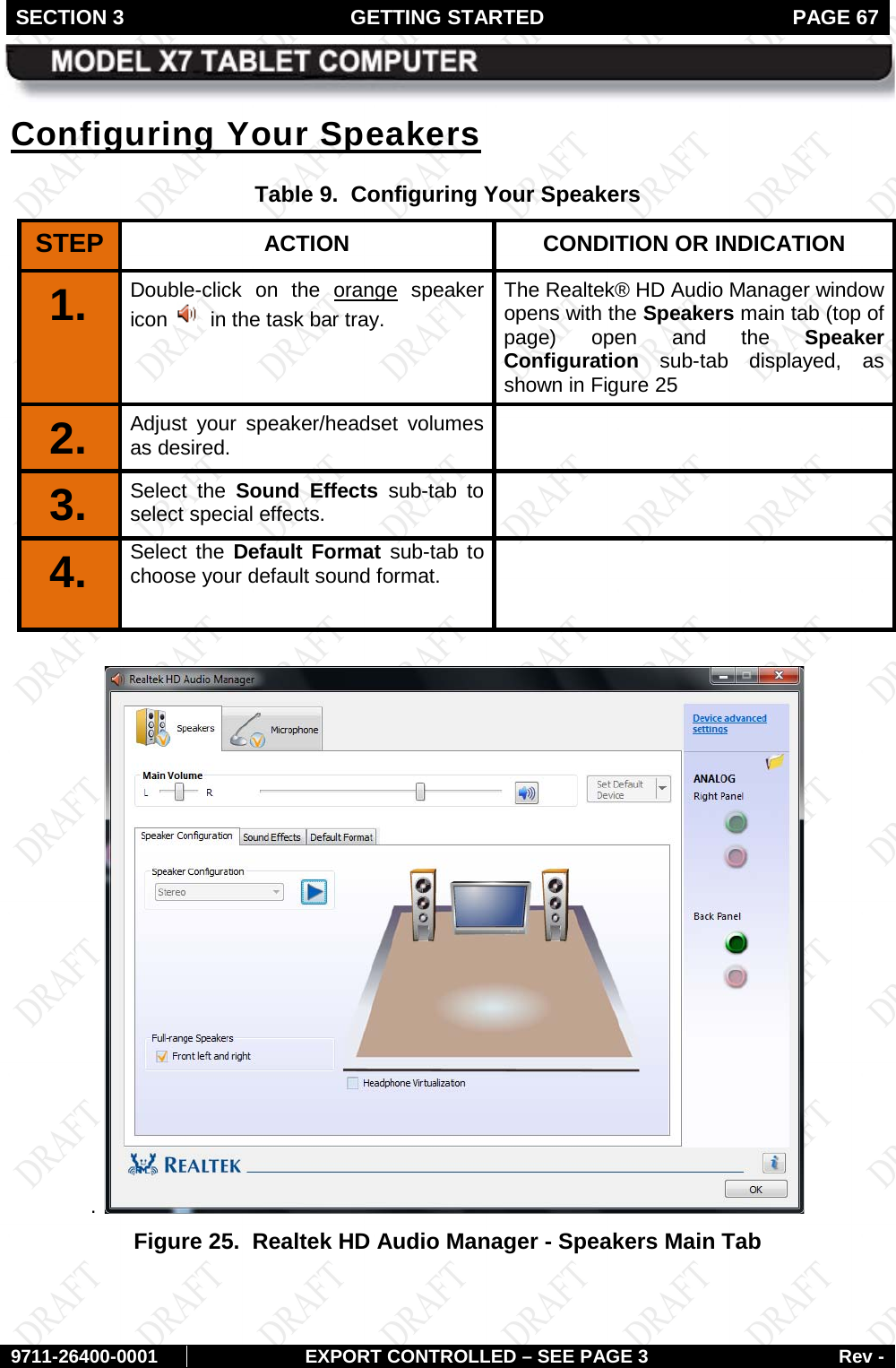
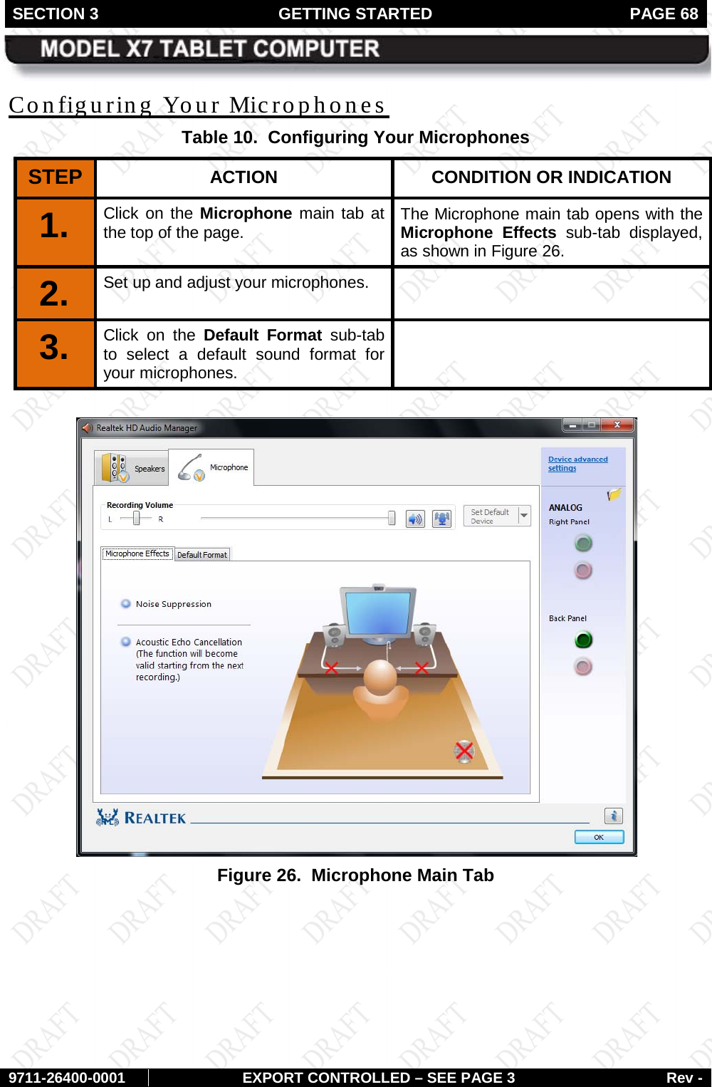
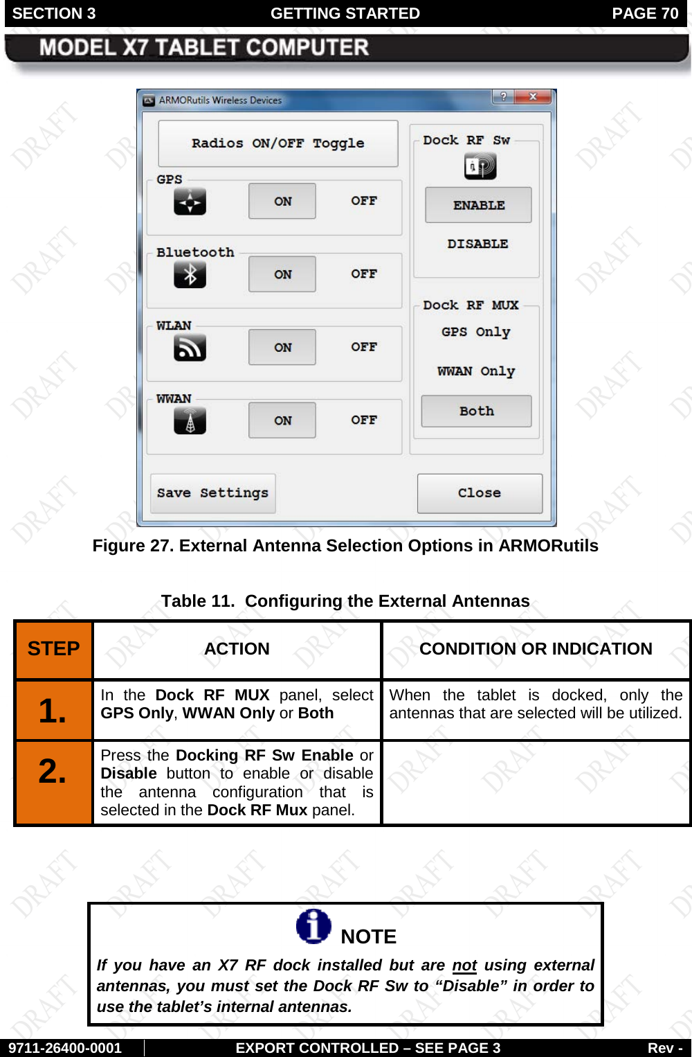


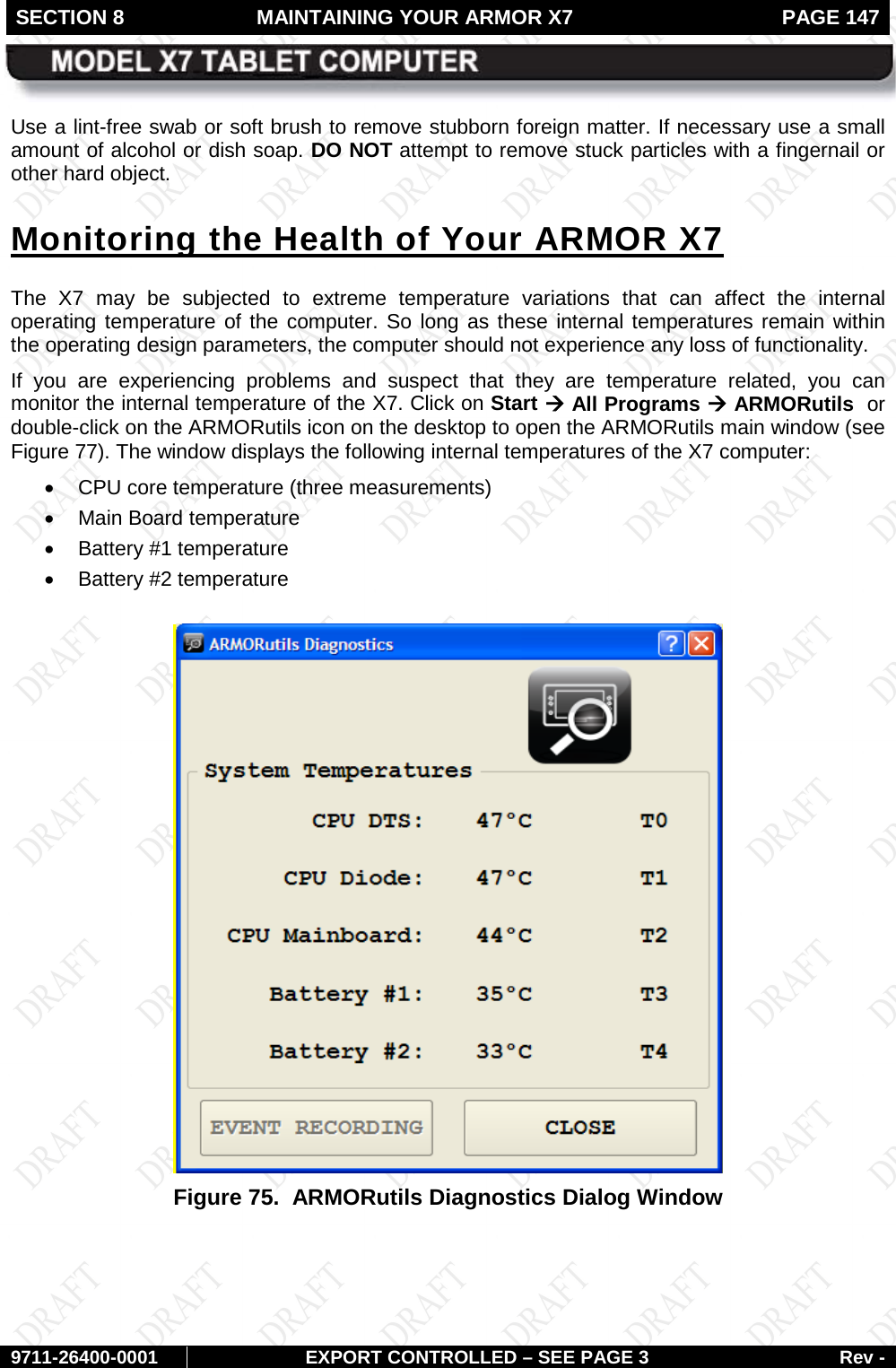
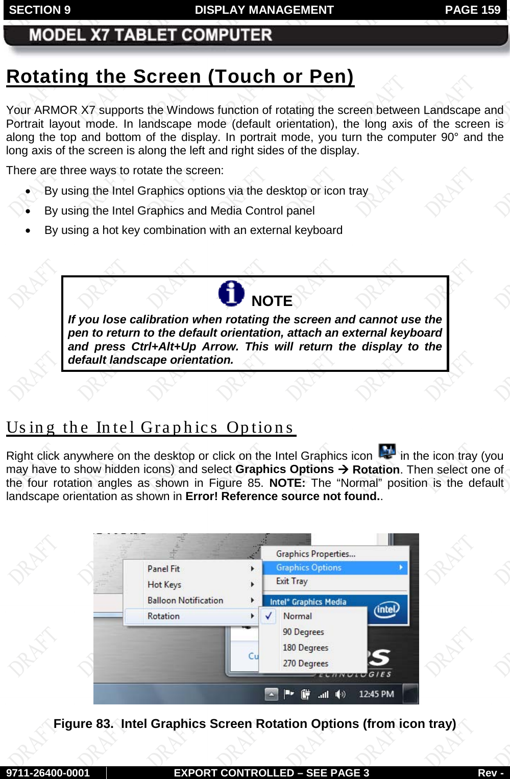
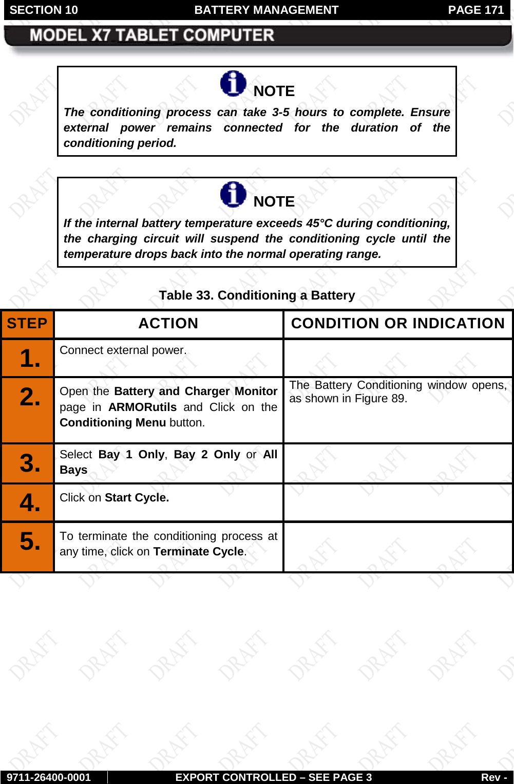
![SECTION 8 MAINTAINING YOUR ARMOR X7 PAGE 149 9711-26400-0001 EXPORT CONTROLLED – SEE PAGE 3 Rev - Figure 76. ARMORutils Event Recording Window [Update image to Win 7]](https://usermanual.wiki/DRS-Tactical-Systems/622ANH.Manual/User-Guide-1371205-Page-149.png)
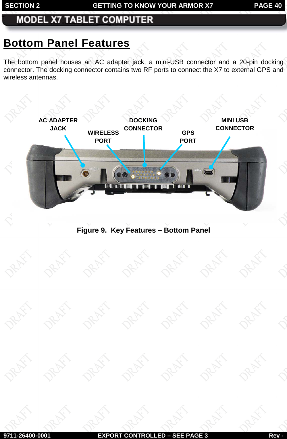
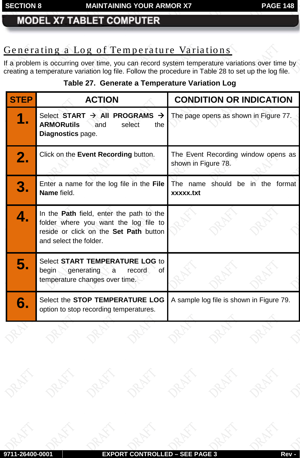
![SECTION 8 MAINTAINING YOUR ARMOR X7 PAGE 150 9711-26400-0001 EXPORT CONTROLLED – SEE PAGE 3 Rev - Figure 77. Sample Temperature Log File [“Core X” column headers do not correspond to Diagnostics dialog window titles (T0, T1, T2….) “System Temp” column header is “Core T2” in the Diagnostics dialog window titles]](https://usermanual.wiki/DRS-Tactical-Systems/622ANH.Manual/User-Guide-1371205-Page-150.png)