DRS Tactical Systems 622ANH Intel Centrino Advanced-N 6200 User Manual 1 of 2
DRS Tactical Systems, Inc. Intel Centrino Advanced-N 6200 Users Manual 1 of 2
UserManual.wiki
>
DRS Tactical Systems
>
622ANH User Manual
>
Users Manual 1 of 2
Contents
1.
Manual
2.
Users Manual 1 of 2
3.
Users Manual 2 of 2
Users Manual 1 of 2
Navigation menu
Upload a User Manual
Namespaces
Wiki Guide
HTML
PDF
Info
Views
User Manual
Discussion / Help
Navigation
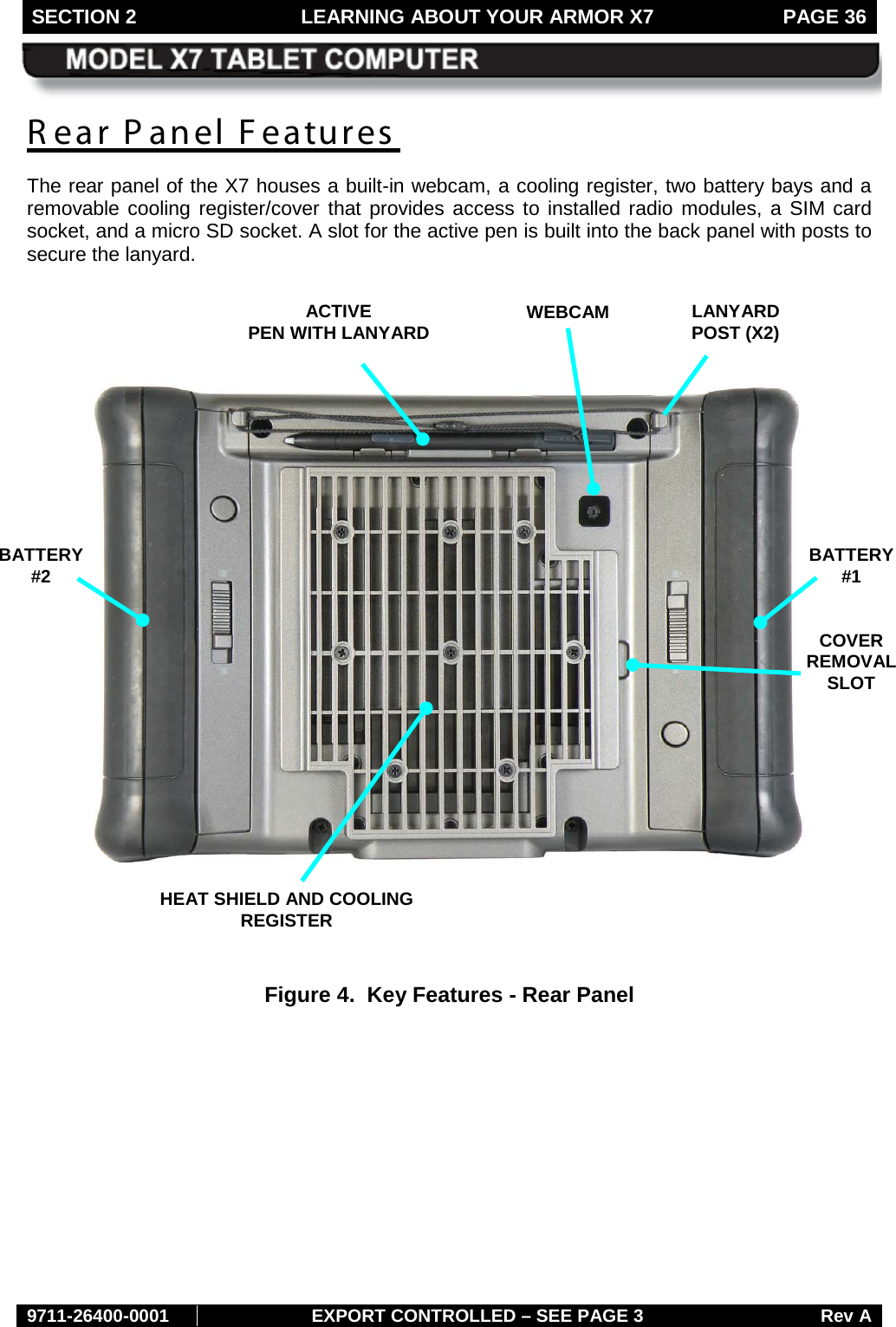
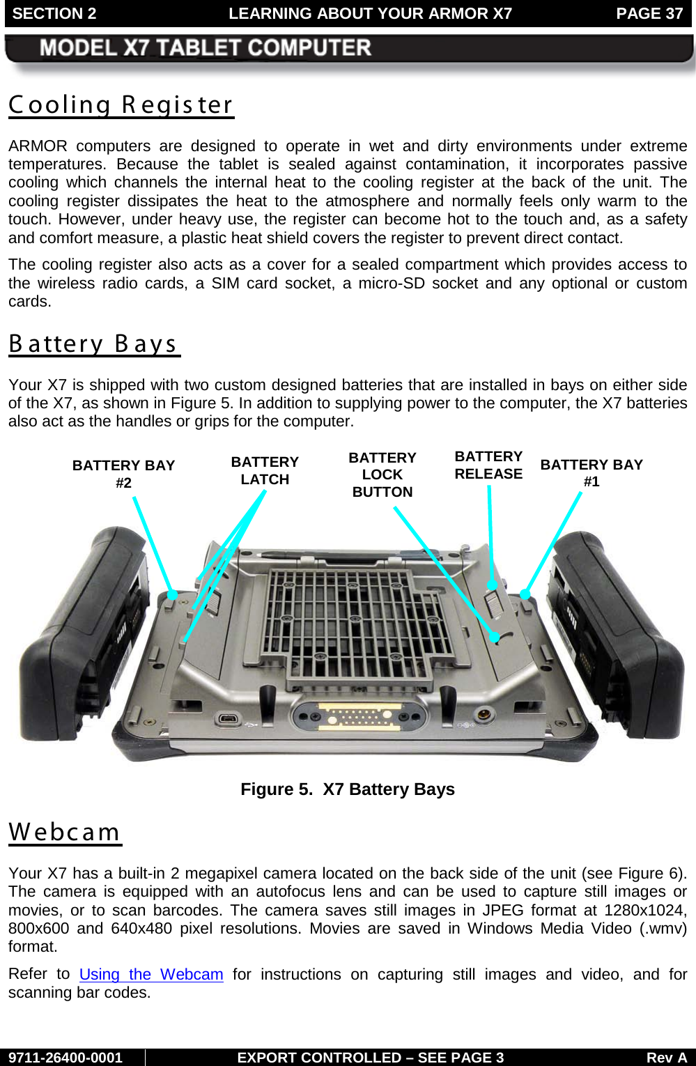
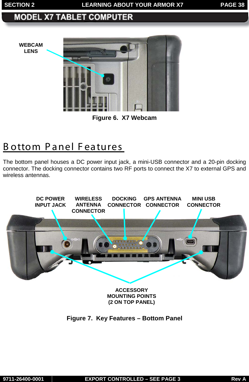
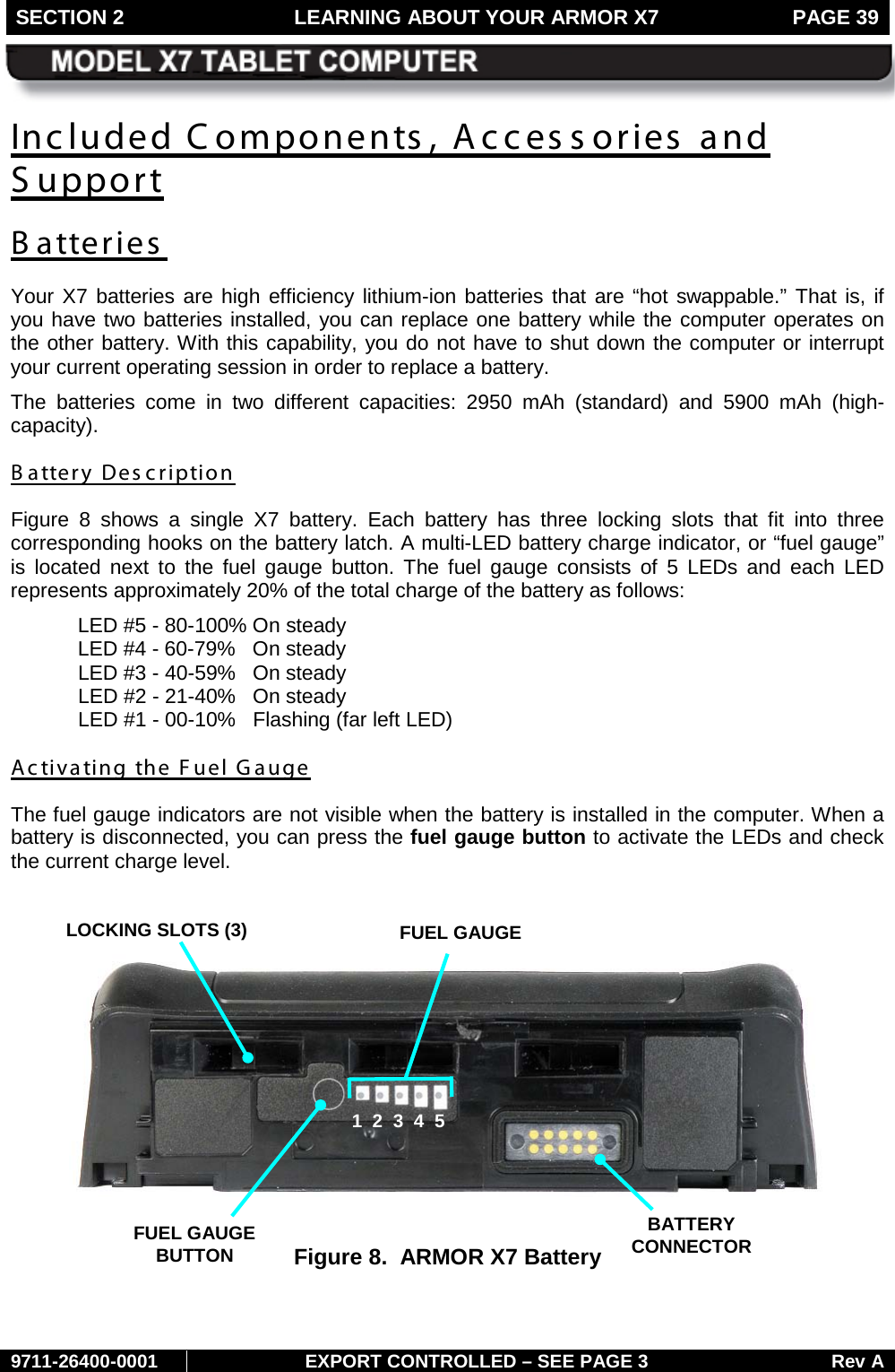
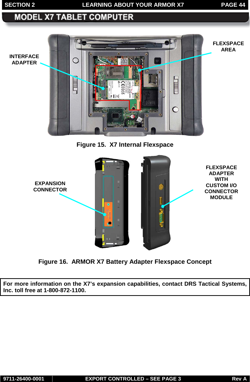
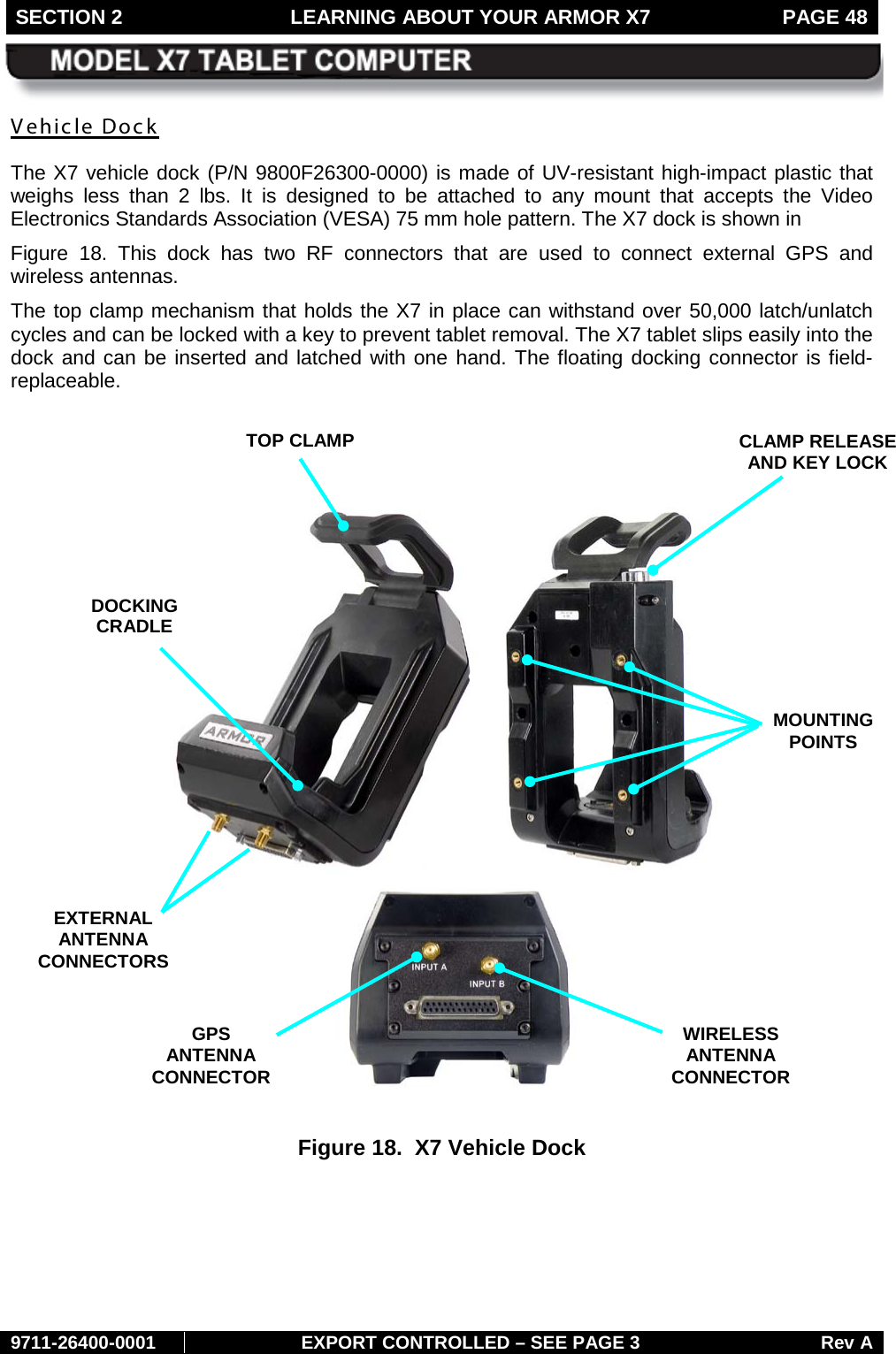
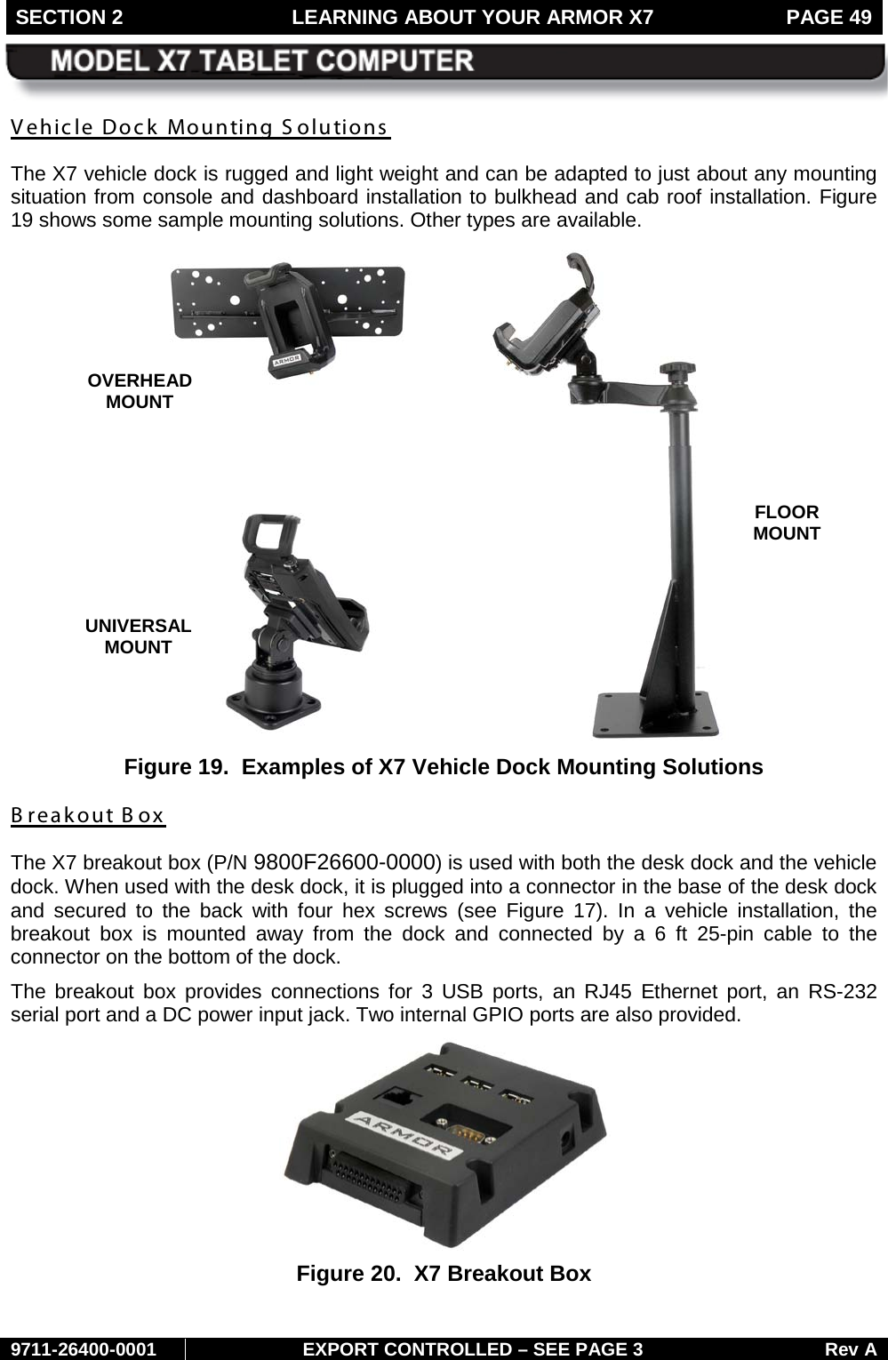
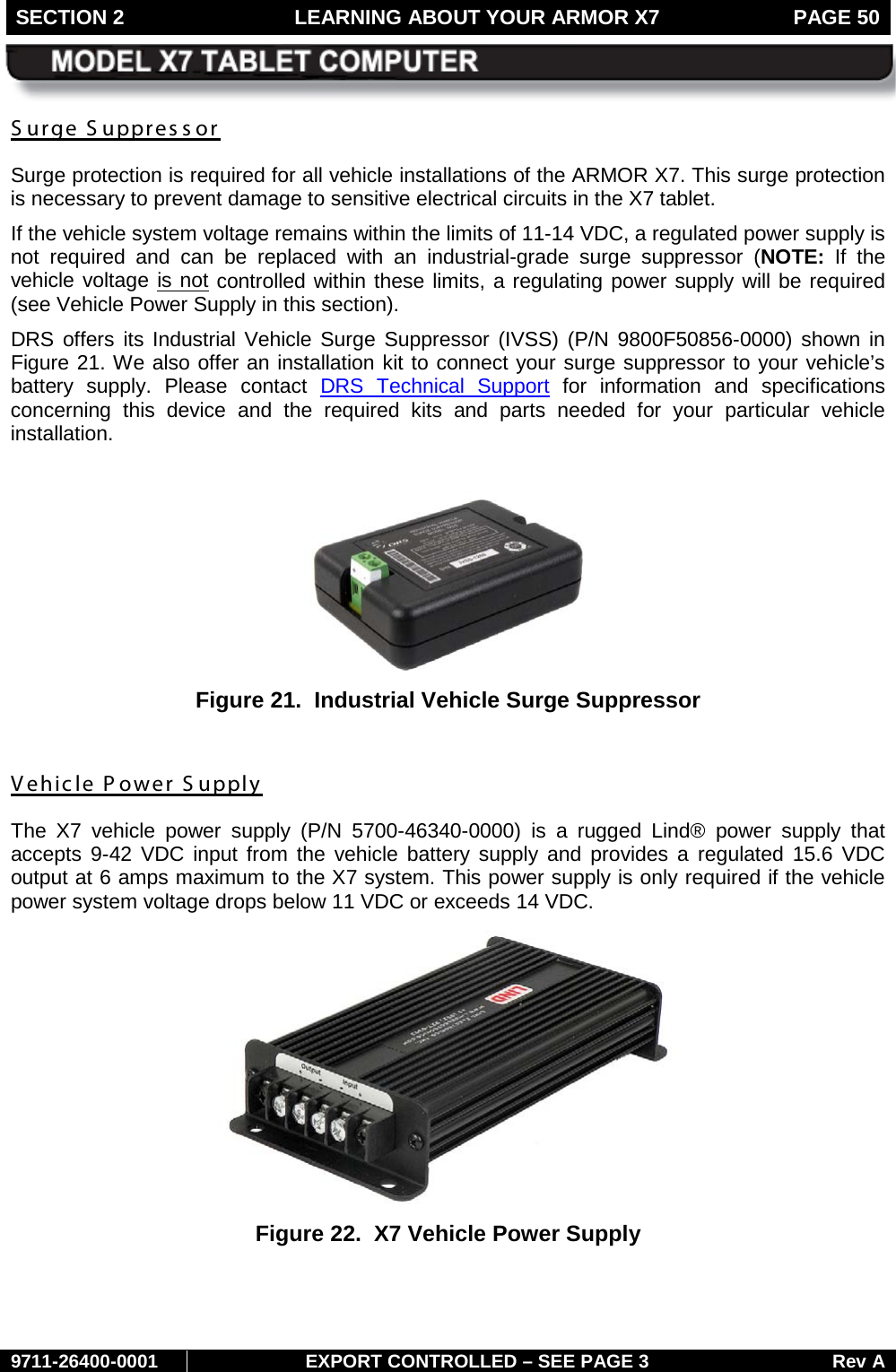
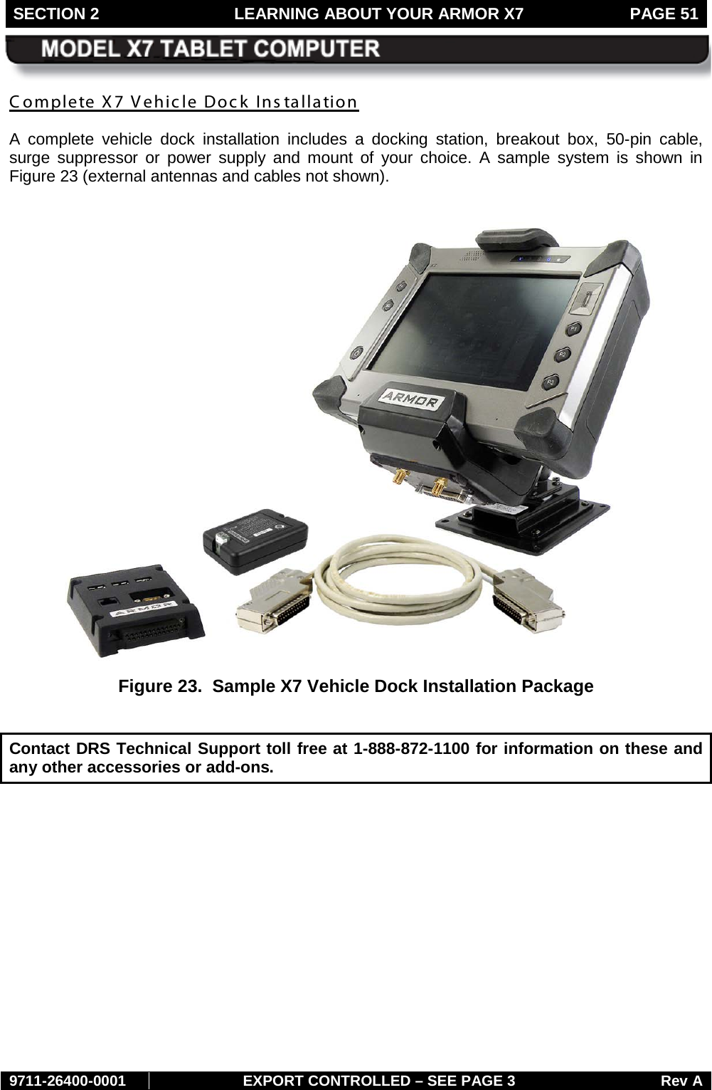
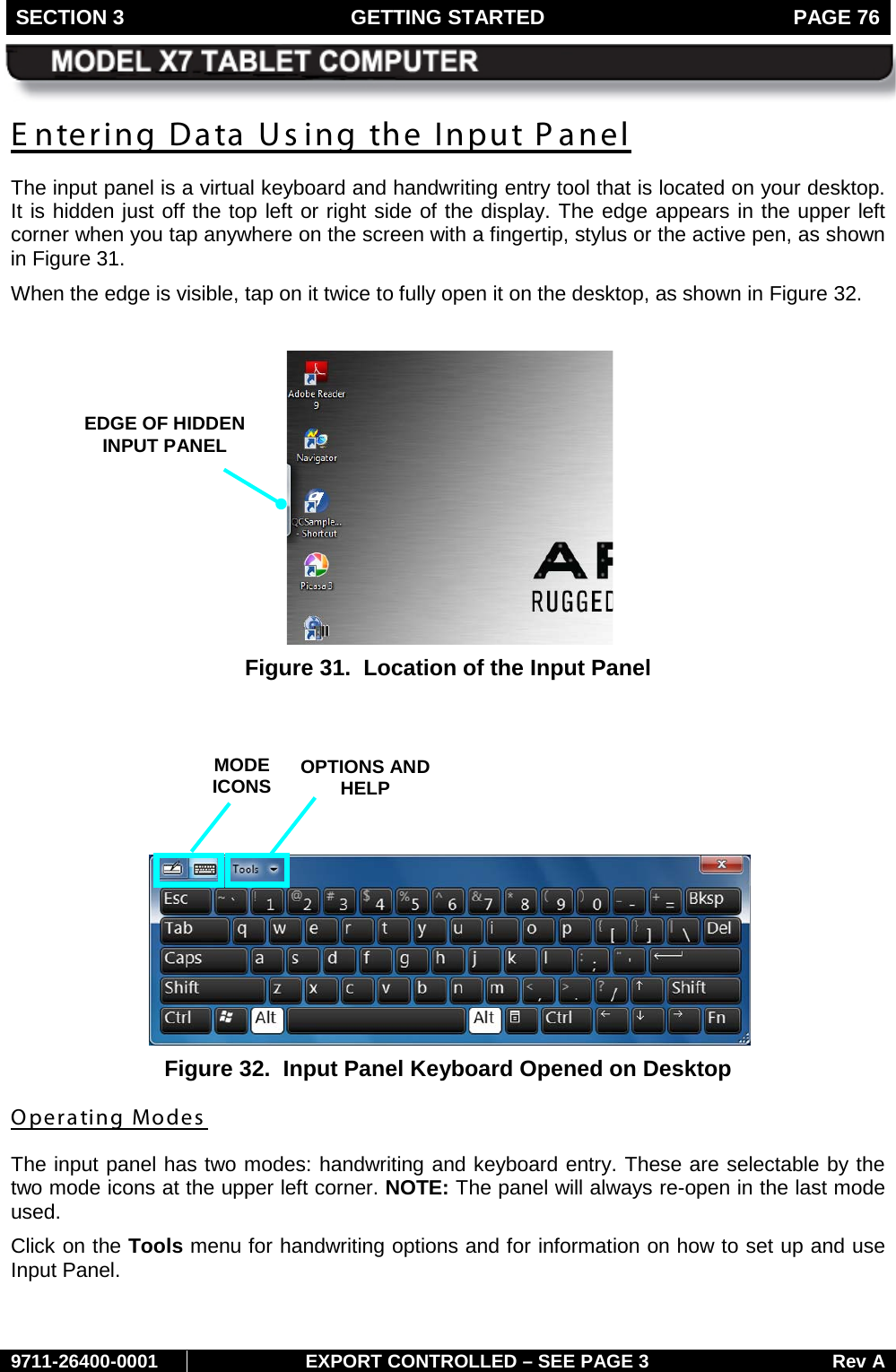
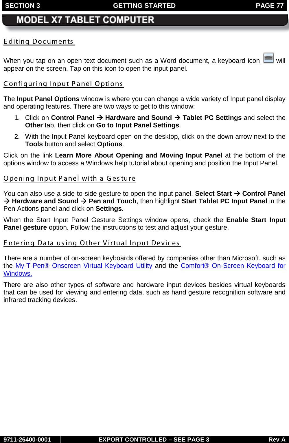
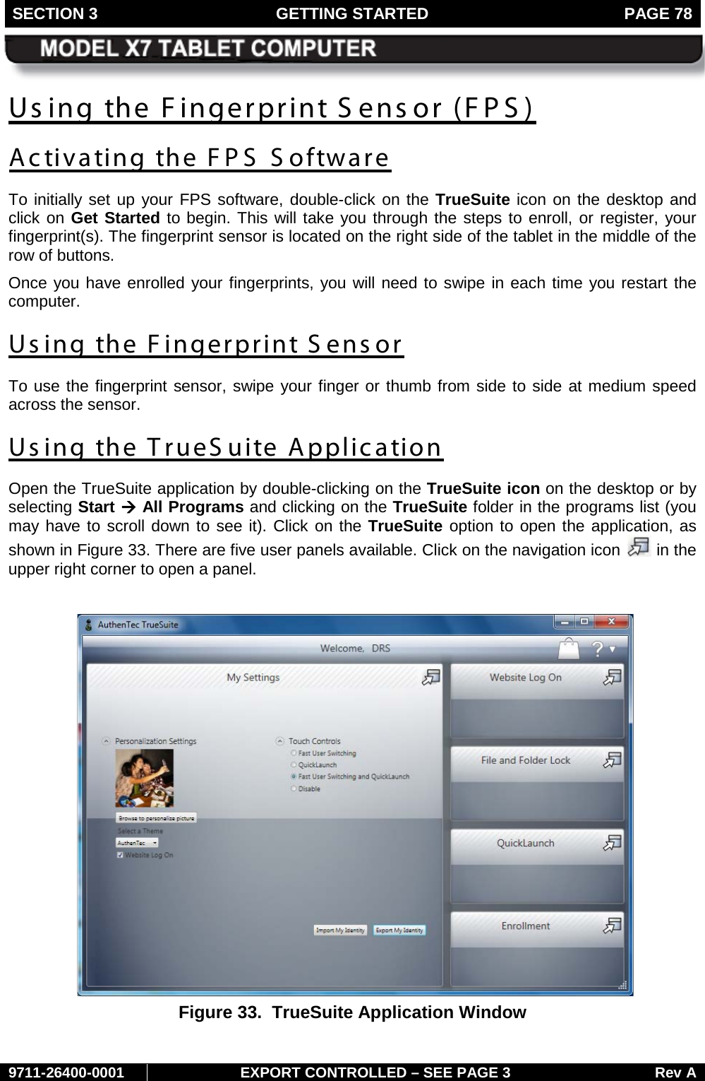
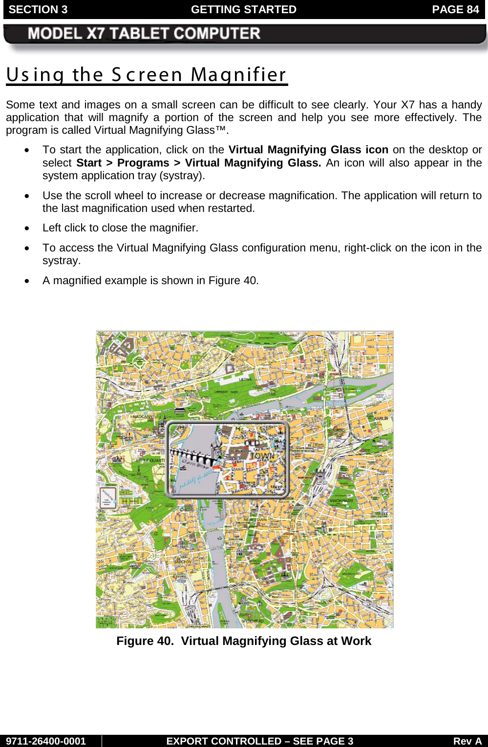
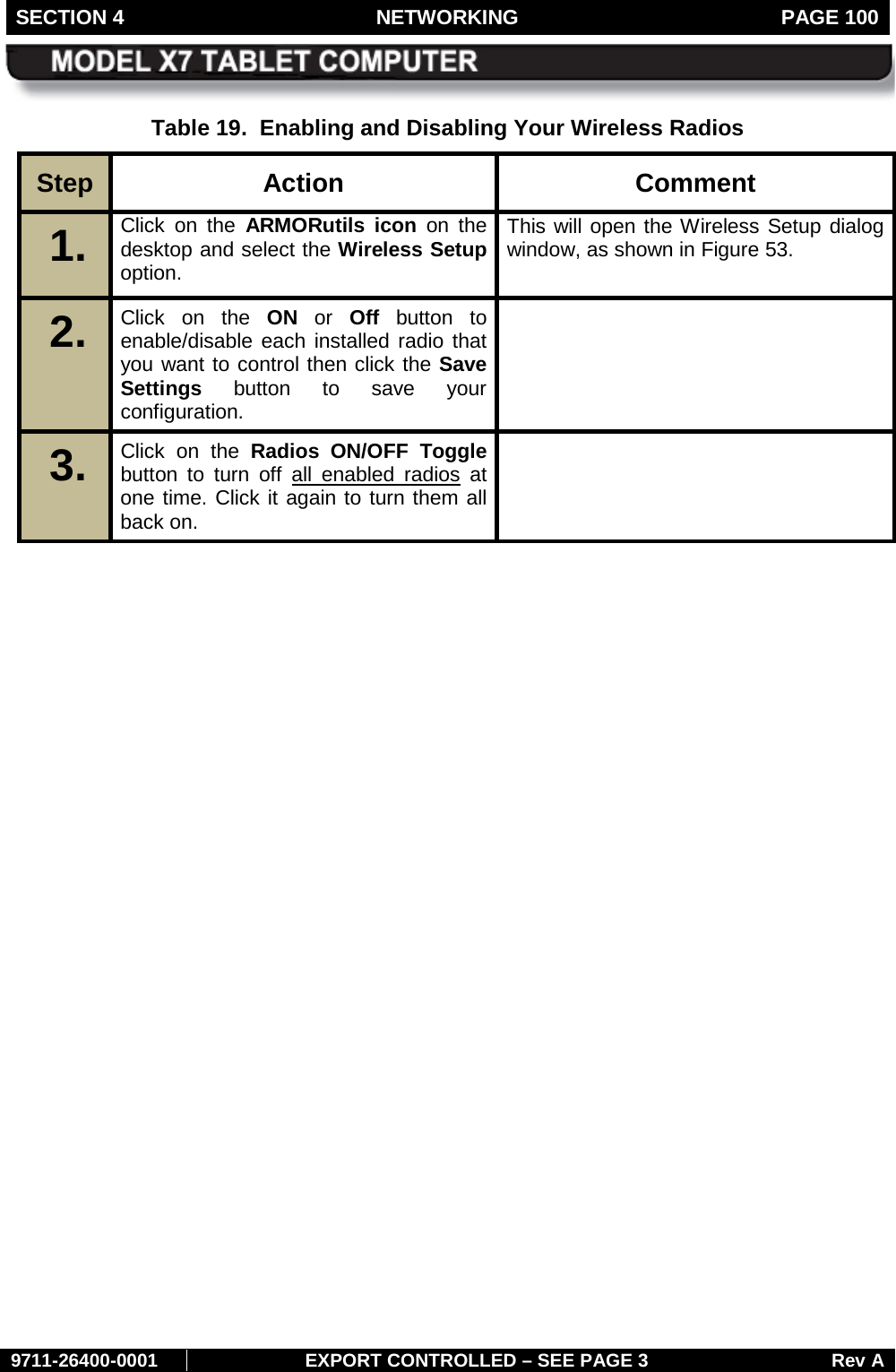
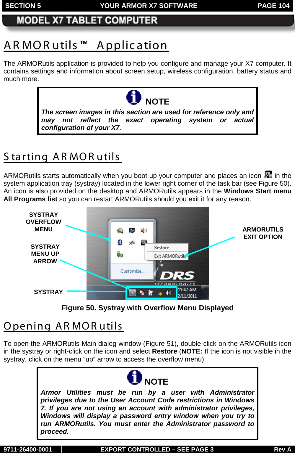
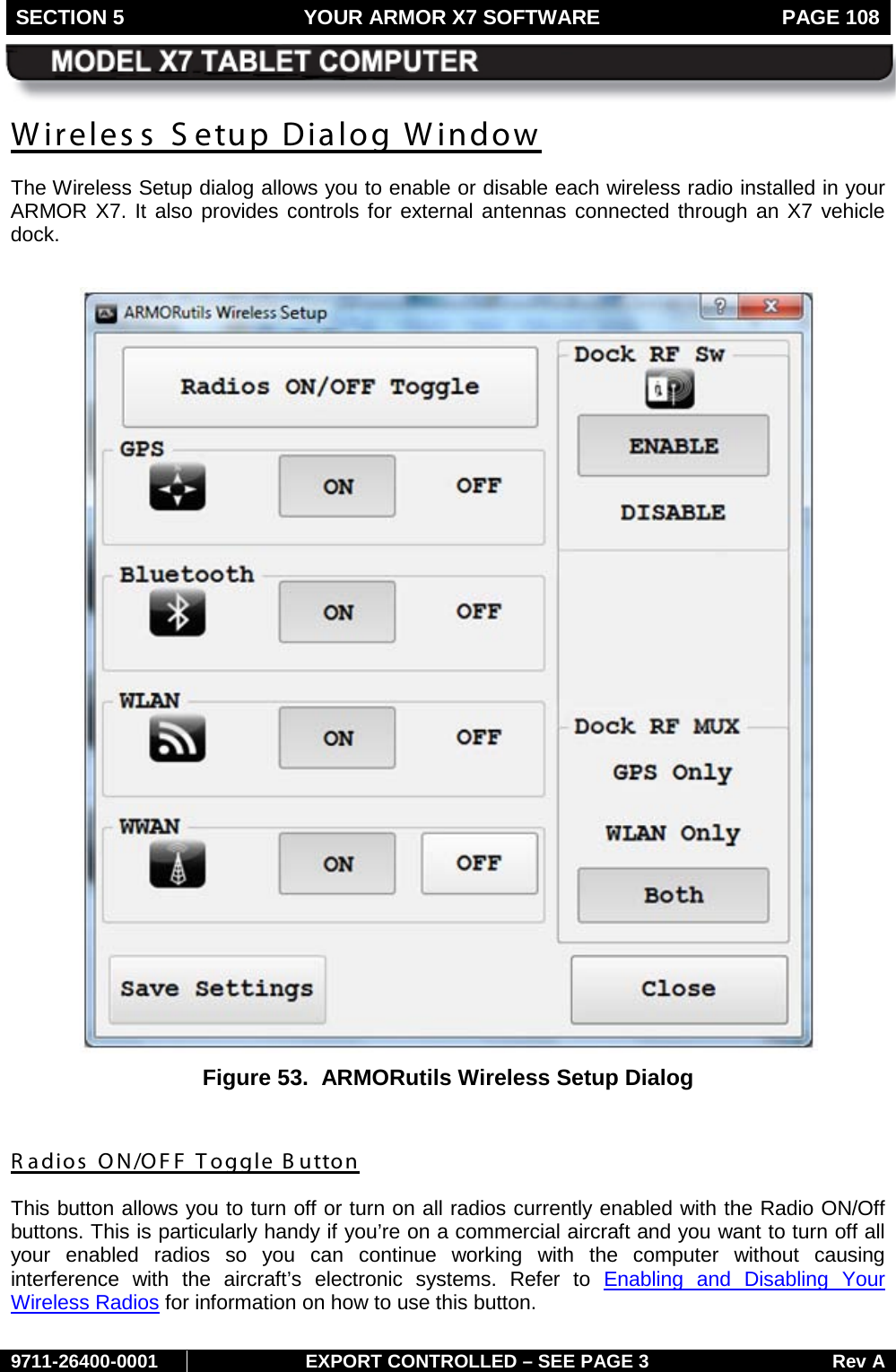
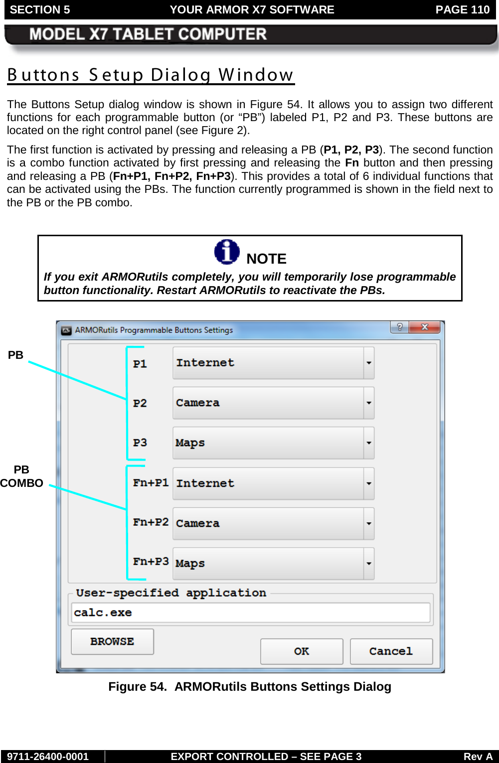
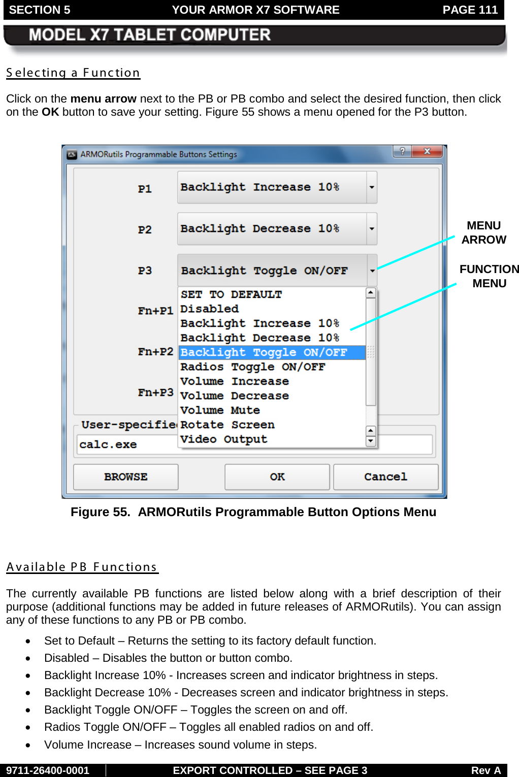
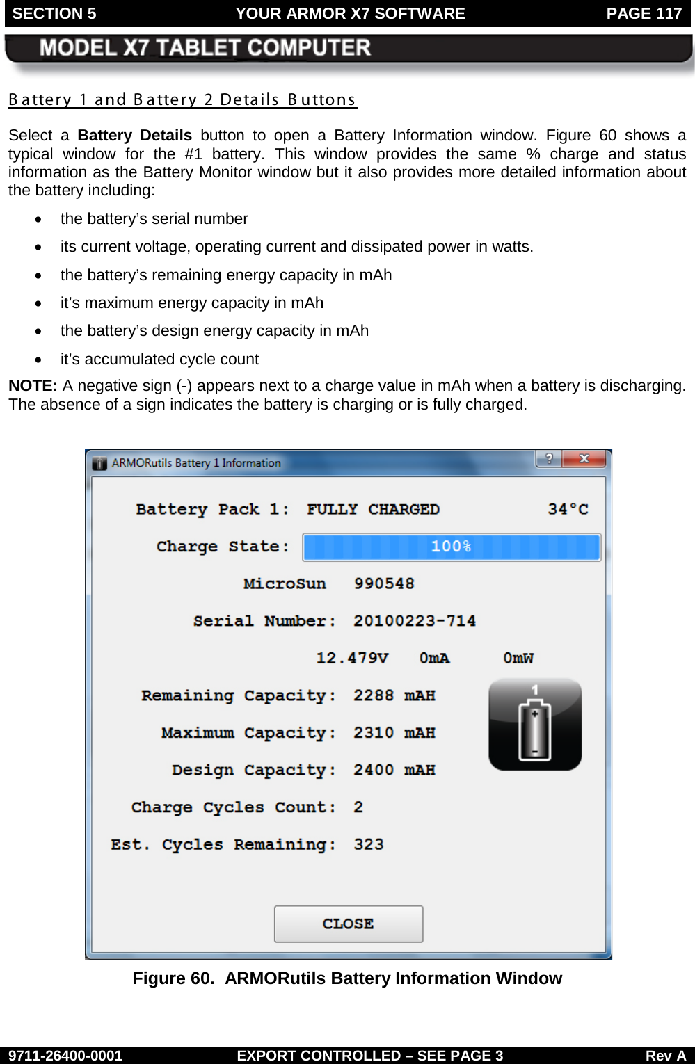
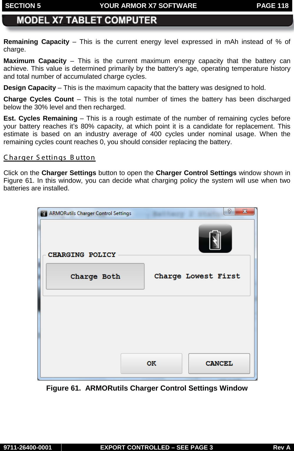
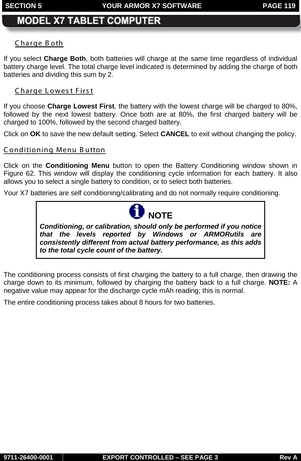
![FRONT MATTER PAGE 12 9711-26400-0001 EXPORT CONTROLLED – SEE PAGE 3 Rev A CAUTION! Recharging the battery must only be carried out in a non-hazardous area using the supplied AC adapter. The definition of hazardous areas can be found in Standard EN 60079-10. CAUTION! DO NOT use this unit in classified areas unsuitable for its security ratings. NE PAS UTILISER CETTE UNITÉ EN ZONES AINSI CLASSÉES IMPROPRES À SA COTE DE SÉCURITÉ CAUTION! When using IEEE 802.11a wireless LAN [in Canada], this product is restricted to indoor use due to its operation in the 5.15- to 5.25-GHz frequency range. Industry Canada requires this product to be used indoors for the frequency range of 5.15 GHz to 5.25 GHz to reduce the potential for harmful interference to co-channel mobile satellite systems. High power radar is allocated as the primary user of the 5.25- to 5.35-GHz and 5.65 to 5.85-GHz bands. These radar stations can cause interference with and/or damage to this device.](https://usermanual.wiki/DRS-Tactical-Systems/622ANH.Users-Manual-1-of-2/User-Guide-1446868-Page-12.png)