DRS Tactical Systems 622ANH Intel Centrino Advanced-N 6200 User Manual 1 of 2
DRS Tactical Systems, Inc. Intel Centrino Advanced-N 6200 Users Manual 1 of 2
Contents
- 1. Manual
- 2. Users Manual 1 of 2
- 3. Users Manual 2 of 2
Users Manual 1 of 2
FRONT MATTER
CONTENT
PAGE 2
9711-26400-0001
EXPORT CONTROLLED – SEE PAGE 3
Rev A
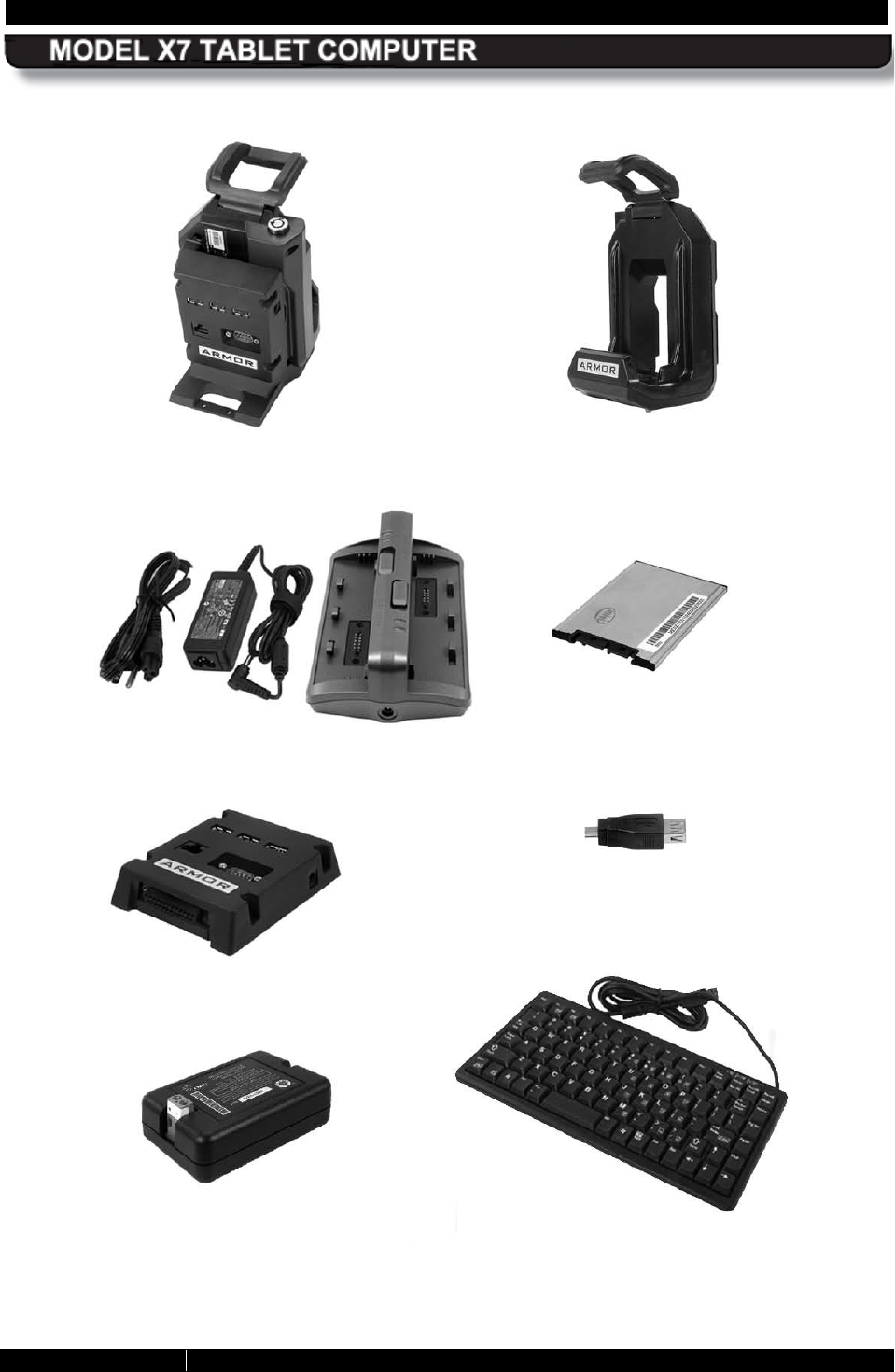
To learn more about ARMOR accessories, please call 1-888-872-1100
VEHICLE DOCK
DESK DOCK
BATTERY CHARGER
SOLID STATE DRIVE
MINI USB ADAPTER
BREAKOUT BOX
SURGE SUPPRESSOR
COMPACT
KEYBOARD

FRONT MATTER
CONTENT
PAGE 3
9711-26400-0001
EXPORT CONTROLLED – SEE PAGE 3
Rev -
MODEL X10 TABLET COMPUTER
Trade Compliance Statement
THIS DOCUMENT CONTAINS TECHNOLOGY CONTROLLED UNDER THE U.S. EXPORT ADMINISTRATION
REGULATIONS (EAR) AND MAY NOT BE EXPORTED OR TRANSFERRED TO ANY FOREIGN PERSON,
FOREIGN COUNTRY OR FOREIGN ENTITY, BY ANY MEANS, WITHOUT PRIOR WRITTEN APPROVAL FROM
THE U.S. DEPARTMENT OF COMMERCE, BUREAU OF INDUSTRY AND SECURITY (BIS) AND DRS
TECHNOLOGIES.
THE INFORMATION DISCLOSED IN THIS DOCUMENT IS PROPRIETARY DATA OF DRS TACTICAL SYSTEMS,
INC., AND MAY NOT BE REPRODUCED, USED, OR DISCLOSED WITHOUT THE PRIOR WRITTEN
AUTHORIZATION OF DRS TACTICAL SYSTEMS, INC.
DISTRIBUTION AUTHORIZED FOR USE PER DOCUMENT NUMBER 9120-02737-
0100. VALIDATION
REQUIRED FOR PLANNING, TESTING, INSPECTION, MANUFACTURING, PROCUREMENT AND QUOTES.
Other Compliance:
United States
• This equipment has been tested and found to comply with the limits for a Class B digital
device, pursuant to Part 15 of the FCC Rules. These limits are designed to provide
reasonable protection against harmful interference in a residential installation. This
equipment radiates radio frequency energy and, if not installed and used in accordance
with the instructions, cautions and warnings contained in this user’s guide, may cause
harmful interference to radio communications. However, there is no guarantee that
interference will not occur in a particular installation. If this equipment does cause
harmful interference to radio or television reception, which can be determined by turning
the equipment off and on, the user is encouraged to try to correct the interference by one
or more of the following measures:
o Reorient this device or move it away from the equipment experiencing interference.
o If connected to an AC outlet, move this device to an outlet on a circuit different from
that to which the device experiencing interference is connected.
o Consult the dealer or an experienced radio/TV technician for help.
• CAUTION: Changes or modifications not expressly approved by DRS Technologies, Inc.
could void the user's authority to operate this equipment.
• This device complies with Part 15 of the FCC Rules. Operation is subject to the following
two condition:
o This device may not cause harmful interference, and
o This device must accept any interference received, including interference that
may cause undesired operation.
• For body-worn operation, this computer has been tested and meets the FCC RF
exposure guidelines set forth for an uncontrolled environment when used with ARMOR
supplied accessories, or accessories designed specifically for this product. Use of other
accessories may not ensure compliance with FCC RF exposure guidelines.
• When using a docking station and external antenna with the WLAN, the antenna should
have an impedance of 50 ohms and a gain not to exceed +5 dBi. To comply with FCC
RF exposure requirements, separation distance of at least 20 cm (8 in.) should be
maintained between the external antenna and all persons.
• Operation within the 5.15–5.25 GHz band is restricted to indoors operations.

FRONT MATTER
CONTENT
PAGE 4
9711-26400-0001
EXPORT CONTROLLED – SEE PAGE 3
Rev A
Canada
• This Class B digital apparatus complies with Industry Canada ICES-003, Issue 4 June 7,
2004 and license-exempt RSS standards RSS-210, Issue No 8 (December 2010), RSS-
132 Issue No. 2 (September 2005), and RSS-133 Issue No. 5 (February 2009).
Operation is subject to the following two conditions: (1) this device may not cause
interference, and (2) this device must accept any interference that may cause undesired
operation of the device.
• Cet appareil numérique de classe B est conforme à Industrie Canada ICES-003, numéro
4 Juin 7, 2004 et exempts de licence normes RSS RSS-210, Issue n ° 8 (Décembre
2010), CNR-132 fascicule n o 2 (Septembre 2005), et RSS-133 fascicule n ° 5 (Février
2009). Son fonctionnement est soumis aux deux conditions suivantes: (1) cet appareil
ne peut pas provoquer d'interférences et (2) cet appareil doit accepter toute interférence
pouvant causer un fonctionnement indésirable de l'appareil.
• This product is restricted to indoor use in the 5.15 to 5.25 GHz frequency range. Industry
Canada requires this product to be used indoors to reduce the potential for harmful
interference to co-channel mobile satellite systems.
• Operation in the 2.4 GHz band: To prevent radio interference to the licensed service, this
device is intended to be operated indoors and away from windows to provide maximum
shielding. Equipment (or its transmit antenna) that is installed outdoors is subject to
licensing.
• Opération dans la bande 2,4 GHz:Pour empêcher que cet appareil cause du brouillage
au service faisant l'objet d'une licence, il doit être utilisé a l'intérieur et devrait être placé
loin des fenêtres afin de fournir un écran de blindage maximal. Si le matériel (ou son
antenne d'émission) est installé à l'extérieur, il doit faire l'objet d'une licence.
• Be advised that high-power radars are allocated as primary users (i.e. priority users) of
the bands 5250–5350 MHz and 5650–5850 MHz and that these radars could cause
interference and/or damage to WLAN devices.
• Under Industry Canada regulations, the WLAN radio transmitter may only operated
using an antenna of a type and maximum (or lesser) gain approved for the transmitter by
Industry Canada. To reduce potential radio interference to other users, the antenna type
and its gain should be so chosen that the equivalent isotropically radiated power (EIRP)
is not more than that necessary for successful communication.
• This radio transmitter 7888B-622ANH has been approved by Industry Canada to operate
with the antenna types listed below with the maximum permissible gain and required
antenna impedance for each antenna type indicated. Antenna types not included in this
list, having a gain greater than the maximum gain indicated for that type, are strictly
prohibited for use with this device.
o Mobile Mark SMW-301-xxxx( surface mount), MGW-301-xxxx (magnetic
mount)radome antennas
o Gain: +5dBi in 2.4GHz and 5GHz bands
o Impedance: 50 ohm

FRONT MATTER
CONTENT
PAGE 5
9711-26400-0001
EXPORT CONTROLLED – SEE PAGE 3
Rev A
Europe
• This X7 tablet computer has been tested for compliance with ATEX directive 94/9/EC.
• This equipment may be operated in AT, BE, BG, CY, CZ, DK, EE, FI, FR, DE, GR, HU,
IS, IE, IT, LV, LT, LU, MT, NL, NO, PL, PT, RO, SK, SI, ES, SE, CH, LE, UK, HR, MK,
TR. Frequency band 5150 – 5350 MHz restricted to indoor use
• FR: 2400 – 2483.5 MHz frequency band restricted to indoor use
• IT: For private use, a general authorization is required if RLAN is used outside of own
premises. For public use, a general authorization is required.
• NO: 2400 – 2483.5 MHz band use is not allowed within the geographical area within a
radius of 20 km from the centre of Ny-Ålesund.
FRONT MATTER PAGE 6
9711-26400-0001
EXPORT CONTROLLED – SEE PAGE 3
Rev A

FRONT MATTER PAGE 7
9711-26400-0001
EXPORT CONTROLLED – SEE PAGE 3
Rev A
NOTICE
Information contained herein is for reference only and does not constitute a commitment on the
part of the manufacturer or any subsequent vendor. They are in no way responsible for any loss
or damage resulting from the use (or misuse) of this publication.
We at DRS strive to make this document as accurate as possible. However, errors do occur and
product information and settings may become out of date as a result of hardware changes or
software updates. DRS Tactical Systems, Inc. reserves the right to revise this publication or to
change its content without notice. Please contact DRS Technical Support for information
concerning updates to this document.
This publication and any accompanying software may not, in whole or in part, be copied,
photocopied, translated or reduced to any machine readable form without prior consent from
DRS Tactical Systems, Inc, except for copies kept by the purchaser for backup purposes.
Brand and product names mentioned in this publication may or may not be registered
trademarks of their respective companies but should be treated as such. They are mentioned
for identification purposes only and are not intended as an endorsement of that product or its
manufacturer. All reproductions of software applications, quoted text and illustrations are
copyrighted by their respective owners.
Copyright 2010-2011, DRS Tactical Systems, Inc., Melbourne, Florida. All Rights Reserved

FRONT MATTER PAGE 8
9711-26400-0001
EXPORT CONTROLLED – SEE PAGE 3
Rev A
This Page Intentionally Left Blank
FRONT MATTER PAGE 9
9711-26400-0001
EXPORT CONTROLLED – SEE PAGE 3
Rev A
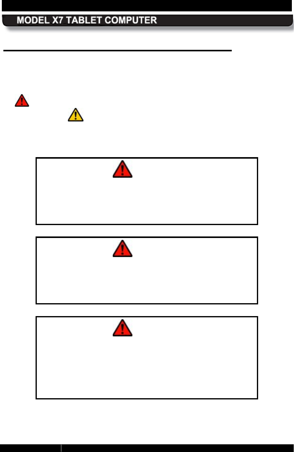
WARNING AND CAUTION S UMMAR Y
The ARMOR X7 complies with all applicable industrial health and safety requirements. However
there are certain safety considerations such as battery safety that you need to be aware of.
Please read and comply with all warnings and cautions in the following summary, elsewhere in
this guide and in all other X7 documentation.
A “ WARNING!” notice indicates a condition or action that could possibly result in injury or
death to the user. A “ CAUTION!” notice indicates a condition or action that could result in
loss of data or damage to equipment.
WARNING!
EXPLOSION HAZARD – DO NOT DISCONNECT WHILE CIRCUIT IS
LIVE UNLESS AREA IS KNOWN TO BE NON-HAZARDOUS.
AVERTISSEMENT-RISQUE D'EXPLOSION - NE PAS DÉBRANCHER
TANT QUE LE CIRCUIT EST SOUS TENSION, À MOINS QU'IL NE
S'AGISSE D'UN EMPLACEMENT NON DANGEREUX.
WARNING!
EXPLOSION HAZARD – BATTERIES MUST ONLY BE CHANGED IN
AN AREA KNOWN TO BE NON-HAZARDOUS.
AVERTISSEMENT-RISQUE D'EXPLOSION - AFIN D'ÉVITER TOUT
RISQUE D'EXPLOSION, S'ASSURER QUE L'EMPLACEMENT EST
DÉSIGNÉ NON DANGEREUX AVANT DE CHANGER LA BATTERIE.
WARNING!
R IS K OF E XPLOS ION IF BATTERY IS REPLACED
BY AN
INCORRECT TYPE. DISPOSE OF USED BATTERIES ACCOR DING
TO INS TR UCTIONS IN THIS US E R 'S GUIDE.
ATTE NTION: R IS QUE D'E XPLOS ION S I LA B ATT
ERIE EST
REMPLACEE PAR UN TYPE INCORRECT. JETER L
ES PILES
USAGEES CONFORMEMENT AUX INS TR UCTIONS
DANS CE
GUIDE D'UTILIS ATE UR ..
FRONT MATTER PAGE 10
9711-26400-0001
EXPORT CONTROLLED – SEE PAGE 3
Rev A
WARNING!
EXPLOSION HAZARD – SUBSTITUTION OF COMPONE NTS MAY
IMPAIR S UITAB ILITY FOR CL AS S I, DIVIS ION 2 OPERATION.
AVERTISSEMENT – RISQUE D’EXPLOSION –
LA SUBSTITUTION
DE COMPOSANTS RISQUE D’AFFECTER
DE CLAS S E I, DIVIS ION 2 FONCTIONNE MENT.
WARNING!
Do not drop or mishandle the batteries, immerse them in water, or
subject them to high heat. Doing so could increase the risk of
explosion or leakage, and possibly cause injury.
WARNING!
The lithium-
ion batteries used in this equipment contain material
that is hazardous to your health. If battery contents come in contact
with the eyes, IMMEDIATELY flush the affected area with clean
water for 15 minutes and have someone else summon medical
attention for you. Unaffected persons should assist the affected
individual in the vital first flushing of the eyes.
WARNING!
If battery material comes in contact with the skin, flush the affected
area with clean water and seek immediate medical treatment.
WARNING!
Disposed lithium-ion batteries that are not fully discharged contain
active salts that can result in an explosion if suddenly exposed to
moisture or water in the environment. To prevent possible injury to
someone finding the battery, please ensure it is fully discharged
before disposing in a domestic or commercial garbage receptacle.
FRONT MATTER PAGE 11
9711-26400-0001
EXPORT CONTROLLED – SEE PAGE 3
Rev A
WARNING!
Changes or modifications not performed by, or expressly authorized
by, DRS Tactical Systems, Inc
could be hazardous to your health,
could cause damage to the equipment
, could void your
authorization to operate the equipment
and could void your
warranty, or could result in all of the above.
WARNING!
Place all shipping bags and packing materials safely out of the
reach of small children, especially infants and toddlers. These
items may pose a choking or suffocation hazard.
CAUTION!
Use this product only in vehicles that can supply
a regulated
+10VDC to +30 VDC (nominal 19 VDC). Voltages outside this range
could cause damage to the computer.
CAUTION!
DO NOT connect the computer to more than one power source at a
time such as with the AC adapter connected to the computer and
vehicle power connected through a docking station. Permanent
damage to the X7 batteries or to the computer itself may result.
CAUTION!
When using the provided AC adapter, the maximum safe ambient
operating temperature is 40°C.
CAUTION!
Use only the battery originally supplied with your ARMOR X7 or
one recommended by DRS.
The use of any other battery could
create a hazardous condition and possibly damage your computer.
Dispose of used batteries in accordance with the information in
Disposing of Your Used Batteries.
FRONT MATTER PAGE 12
9711-26400-0001
EXPORT CONTROLLED – SEE PAGE 3
Rev A
CAUTION!
Recharging the battery must only be carried out in a non-
hazardous area using the supplied AC adapter. The definition of
hazardous areas can be found in Standard EN 60079-10.
CAUTION!
DO NOT use this unit in classified areas unsuitable for its security
ratings.
NE PAS UTILISER CETTE UNITÉ EN ZONES AINSI
CLASSÉES IMPROPRES À SA COTE DE SÉCURITÉ
CAUTION!
When using IEEE 802.11a wireless LAN [in Canada], this product is
restricted to indoor use due to its operation in the 5.15- to 5.25-
GHz frequency range. Industry Canada requires this product to be
used indoors for the frequency range of 5.15 GHz to 5.25 GHz to
reduce the potential for harmful interference to co-channel mobile
satellite systems. High power radar is allocated as the primary
user of the 5.25- to 5.35-GHz and 5.65 to 5.85-GHz bands. These
radar stations can cause interference with and/or damage to this
device.

FRONT MATTER PAGE 13
9711-26400-0001
EXPORT CONTROLLED – SEE PAGE 3
Rev A
Quick Links: Section 1 2 3 4 5 6 7 8 9 10 A B C List of Figures List of Tables Acronyms Glossary
Table of Contents
WAR NING AND CAUTION S UMMAR Y ..................................................... 9
1. WE LCOME AND INTR ODUCTION ...................................................... 25
Your ARMOR X7 Purchase ...................................................................................................26
About This Guide ...................................................................................................................27
Viewing, Navigating, and Printing this Guide ..........................................................................27
Please Help Us Maintain Top Quality Documentation ............................................................27
2. LE AR NING AB OUT YOUR ARMOR X7 ............................................... 29
Front and Top Panel Features ...............................................................................................30
Display ..............................................................................................................................31
Controls .............................................................................................................................31
Indicator Panel ..................................................................................................................34
Speaker .............................................................................................................................35
Noise Cancelling Stereo Microphones ...............................................................................35
Rear Panel Features ..............................................................................................................36
Cooling Register ................................................................................................................37
Battery Bays ......................................................................................................................37
Webcam ............................................................................................................................37
Bottom Panel Features ..........................................................................................................38
Included Components, Accessories and Support ...................................................................39
Batteries ............................................................................................................................39
Active Pen with Tether .......................................................................................................40
AC Adapter and Power Cord .............................................................................................40
ARMOR Cloth ...................................................................................................................41
Thermal Transfer Pads ......................................................................................................41
Subscriber Identity Module (SIM) Card Support.................................................................42
Secure Digital (SD) Card Reader Support .........................................................................42
Trusted Platform Module (TPM) Support ...........................................................................43
Flexspace™ Expansion .....................................................................................................43
Optional Add-ons and Accessories for Your X7 .....................................................................45
Gobi® Wireless Wide Area Network (WWAN) Card ..........................................................45
u-blox® GPS Receiver Card ..............................................................................................45
Compact Keyboard ............................................................................................................45

FRONT MATTER PAGE 14
9711-26400-0001
EXPORT CONTROLLED – SEE PAGE 3
Rev A
External Battery Charger ...................................................................................................45
Mini-USB Adapter ..............................................................................................................46
D-Ring Set .........................................................................................................................46
Screen Protector ...............................................................................................................46
Docking Stations ...............................................................................................................47
X7 Specifications ...................................................................................................................52
3. GETTING STARTED ............................................................................ 57
Installing and Charging the Batteries .....................................................................................58
Turning On your X7 for the First Time ....................................................................................61
Turning the Computer On Normally .......................................................................................62
Turning the Computer Off Normally .......................................................................................62
Emergency Shutdown ............................................................................................................63
Putting the Computer into Sleep Mode ..................................................................................63
Indications that your X7 is Asleep ......................................................................................63
Putting the Computer into Hibernate Mode ............................................................................63
Indicator State Summary .......................................................................................................64
Configuring and Controlling your Wireless Radios .................................................................66
Installing a Micro SD/SDHC Card ..........................................................................................66
Installing the Optional D-Rings ...............................................................................................66
Configuring your Audio System ..............................................................................................67
Operating the X7 Display .......................................................................................................69
Selecting the Display Mode ...............................................................................................69
Adjusting Screen Brightness..............................................................................................70
Working with the Pen Screen ............................................................................................72
Working with the Touch Screen .........................................................................................74
Entering Data Using the Input Panel ..................................................................................76
Using the Fingerprint Sensor (FPS) .......................................................................................78
Activating the FPS Software ..............................................................................................78
Using the Fingerprint Sensor .............................................................................................78
Using the TrueSuite Application ........................................................................................78
TrueSuite Options and Settings .........................................................................................79
Uninstalling your Fingerprint Software ...............................................................................79
Using the Webcam ................................................................................................................80
Capturing Images and Video .............................................................................................80

FRONT MATTER PAGE 15
9711-26400-0001
EXPORT CONTROLLED – SEE PAGE 3
Rev A
Scanning a Barcode ..........................................................................................................81
Using the Screen Magnifier ....................................................................................................84
Tips for Proper Use and Care Of Your X7 ..............................................................................85
4. NE TWOR K ING ..................................................................................... 87
Managing your Wi-Fi Connections .........................................................................................87
Managing your Bluetooth Connections ..................................................................................89
Managing your Ethernet Connection ......................................................................................92
Activating the Optional Gobi® WWAN Radio .........................................................................94
Using the OneClickInternet Application .............................................................................94
Using the Network Driver Interface Specification (NDIS) ...................................................94
Important Notes about Using NDIS: ...................................................................................95
Activating the Optional GPS Receiver ....................................................................................96
The u-center GPS Application Window ..............................................................................97
u-center User’s Guide........................................................................................................97
Assisted GPS ....................................................................................................................97
Enabling and Disabling Your Wireless Radios .......................................................................99
Wireless Signal Quality ........................................................................................................ 101
Using your Radios with an X7 Vehicle Docking Station ........................................................ 101
5. YOUR ARMOR X7 SOFTWARE ........................................................ 103
ARMORutils™ Application ................................................................................................... 104
Starting ARMORutils ....................................................................................................... 104
Opening ARMORutils ...................................................................................................... 104
Exiting from ARMORutils ................................................................................................. 105
ARMORutils Main Window .............................................................................................. 105
Backlight Setup Dialog Window ....................................................................................... 106
Wireless Setup Dialog Window ........................................................................................ 108
Buttons Setup Dialog Window ......................................................................................... 110
Configuration Dialog Window .......................................................................................... 113
Battery Monitor Dialog ..................................................................................................... 116
Screen Setup Dialog Window .......................................................................................... 121
Diagnostics Dialog Window ............................................................................................. 123
ARMORutils About Window ............................................................................................. 127
Getting Started with Windows 7 ........................................................................................... 128
Help for Windows ............................................................................................................ 128

FRONT MATTER PAGE 16
9711-26400-0001
EXPORT CONTROLLED – SEE PAGE 3
Rev A
Windows Display Utilities ..................................................................................................... 128
Pen and Touch Utility ...................................................................................................... 129
Tablet PC Settings Utility ................................................................................................. 134
Pen Tablet Properties Utility ............................................................................................ 137
TrueSuite™ Fingerprint Recognition Software ..................................................................... 144
Using the TrueSuite Application ...................................................................................... 144
Realtek® HD Audio Manager Application ............................................................................ 145
Picasa 3® Image Capture .................................................................................................... 146
Virtual Magnifying Glass™ ................................................................................................... 147
6. TR OUB LE S HOOTING ....................................................................... 149
Isolating the Problem ........................................................................................................... 149
Troubleshooting Flowcharts ................................................................................................. 153
TS-01 Tablet will not power up ........................................................................................ 153
TS-02 Tablet will not start boot process. Power is ok ...................................................... 154
TS-03 Tablet will not boot into Windows .......................................................................... 155
TS-04 Tablet will not recognize a battery ......................................................................... 156
TS-05 Tablet is locked up ................................................................................................ 157
TS-06 Cannot connect to wireless network ..................................................................... 158
7. MAINTAINING YOUR ARMOR X7 ..................................................... 161
Removing and Replacing the Batteries ................................................................................ 161
Removing the Heat Shield and Cooling Register ................................................................. 162
Installing the Cooling Register and Heat Shield ................................................................... 164
Installing a SIM Card ........................................................................................................... 168
Installing a Micro SD or SDHC Card .................................................................................... 170
Changing the BIOS Settings ................................................................................................ 172
Returning the BIOS to its Default Settings ........................................................................... 174
Changing the Power Button Default Action .......................................................................... 175
Creating an Event Log ......................................................................................................... 177
Caring For the Display Screen ............................................................................................. 179
Cleaning the Tablet Case .................................................................................................... 180
8. DIS PLAY MANAGE ME NT ................................................................. 181
Adjusting the Brightness ...................................................................................................... 181
Automatic Brightness Adjustment .................................................................................... 181
Manual Brightness Adjustment ........................................................................................ 181

FRONT MATTER PAGE 17
9711-26400-0001
EXPORT CONTROLLED – SEE PAGE 3
Rev A
Calibrating the Display ......................................................................................................... 183
Rotating the Screen (Touch or Pen) ..................................................................................... 184
Using the Intel Graphics Options ..................................................................................... 184
Using the Intel Graphics and Media Control Panel .......................................................... 185
Using a Keyboard “Hot Key” Combination ....................................................................... 186
9. BATTERY MANAGEMENT ................................................................ 187
Safety and Handling Considerations for Your Batteries ........................................................ 188
When to Charge a Battery ................................................................................................... 189
New Batteries .................................................................................................................. 189
Currently Installed Batteries............................................................................................. 189
Removed Batteries .......................................................................................................... 189
Depleted Batteries ........................................................................................................... 189
Fully Depleted and Overly Discharged Batteries .............................................................. 190
Un-recoverable Batteries ................................................................................................. 190
Avoiding Overly-Discharging Your Batteries .................................................................... 191
What to Do for an Overly-Discharged Battery .................................................................. 191
How to Charge Your Batteries ............................................................................................. 192
Charging Times ............................................................................................................... 192
Charging Temperatures ................................................................................................... 192
Setting the Charging Policy ............................................................................................. 193
How to Tell When Batteries Have Finished Charging ...................................................... 194
Using the Optional X7 External Battery Charger .............................................................. 194
Battery Operating Times ...................................................................................................... 194
Operating Under Low Battery Conditions ............................................................................. 195
Low Battery Level Alarm .................................................................................................. 195
Reserved Battery Level Alarm ......................................................................................... 196
Critical Battery Level Alarm ............................................................................................. 196
What to Do if You Get a Low Battery Alert ....................................................................... 196
Fully Depleted (Overly Discharged) Batteries .................................................................. 197
Avoiding Overly-Discharging Your Batteries .................................................................... 197
Battery Capacity and Charge ............................................................................................... 197
Maximum Capacity .......................................................................................................... 197
Checking your Battery’s Capacity .................................................................................... 198
Discharge/Recharge Cycles................................................................................................. 198

FRONT MATTER PAGE 18
9711-26400-0001
EXPORT CONTROLLED – SEE PAGE 3
Rev A
How to Optimize Battery Operating Time ............................................................................. 198
Monitoring Battery Status ..................................................................................................... 198
Using the Desktop Battery Monitor Window ..................................................................... 199
Using the ARMORutils Battery Monitor Dialog ................................................................. 200
Generating an Event Log ................................................................................................. 200
Battery Conditioning/Calibration ........................................................................................... 201
When to Replace a Battery .................................................................................................. 204
Nominal Usage ................................................................................................................ 204
Heavy Usage ................................................................................................................... 204
Determining a Battery’s Age ............................................................................................ 204
Before you Dispose of a Battery ...................................................................................... 204
Your Battery’s Warranty .................................................................................................. 205
Where to Purchase Replacement Batteries ......................................................................... 205
How to Store Batteries When Not in Use ............................................................................. 205
Short-Term Storage ......................................................................................................... 205
Long-Term Storage ......................................................................................................... 205
Battery Tips for Best Performance ....................................................................................... 206
Disposing of Your Used Batteries ........................................................................................ 207
Disposal .......................................................................................................................... 207
Recycling ......................................................................................................................... 207
10. DR S TE CHNICAL S UPPORT .......................................................... 209
Before You Contact Us ........................................................................................................ 209
How to Return a Product to DRS ......................................................................................... 209
If You Need Information ....................................................................................................... 211
How to Locate and Interpret your X7 Serial Number ............................................................ 212
Your ARMOR Warranty ....................................................................................................... 213
General Information ......................................................................................................... 213
Length of Warranty .......................................................................................................... 213
Terms and Conditions ..................................................................................................... 213
Additional Information ...................................................................................................... 214
AC R ONYMS ........................................................................................... 215
GLOSSARY ........................................................................................... 216
APPE NDIX A .......................................................................................... 217

FRONT MATTER PAGE 19
9711-26400-0001
EXPORT CONTROLLED – SEE PAGE 3
Rev A
Explanation of Active Pen Side Button Options .................................................................... 217
APPE NDIX B .......................................................................................... 219
Using the X7 External Battery Charger ................................................................................ 219
Charger LED Status Indications ........................................................................................... 220
APPE NDIX C .......................................................................................... 221
Sierra OneClick Connection Manager User Manual ............................................................. 221

FRONT MATTER PAGE 20
9711-26400-0001
EXPORT CONTROLLED – SEE PAGE 3
Rev A
Quick Links: Section 1 2 3 4 5 6 7 8 9 10 A B C Table of Contents List of Tables Acronyms Glossary
List of Figures
Figure 1. ARMOR X7 Key Features – Front View ....................................................................30
Figure 2. X7 Control Panels .....................................................................................................31
Figure 3. X7 Indicator Panel .....................................................................................................34
Figure 4. Key Features - Rear Panel ........................................................................................36
Figure 5. X7 Battery Bays ........................................................................................................37
Figure 6. X7 Webcam ..............................................................................................................38
Figure 7. Key Features – Bottom Panel....................................................................................38
Figure 8. ARMOR X7 Battery ...................................................................................................39
Figure 9. The ARMOR X7 Pen .................................................................................................40
Figure 10. X7 AC Adapter ........................................................................................................41
Figure 11. ARMOR Microfiber Cleaning Cloth ..........................................................................41
Figure 12. Thermal Transfer Pads ............................................................................................41
Figure 13. SIM Card .................................................................................................................42
Figure 14. Micro SD Card ........................................................................................................42
Figure 15. X7 Internal Flexspace..............................................................................................44
Figure 16. ARMOR X7 Battery Adapter Flexspace Concept .....................................................44
Figure 17. X7 Desk Dock .........................................................................................................47
Figure 18. X7 RF Vehicle Dock ................................................................................................48
Figure 19. Examples of X7 Vehicle Dock Mounting Solutions ..................................................49
Figure 20. X7 Breakout Box .....................................................................................................49
Figure 21. Industrial Vehicle Surge Suppressor .......................................................................50
Figure 22. X7 Vehicle Power Supply ........................................................................................50
Figure 23. Sample X7 Vehicle Dock Installation Package ........................................................51
Figure 24. X7 Internal Block Diagram .......................................................................................55
Figure 25. X7 Batteries Positioned for Installation ....................................................................58
Figure 26. X7 Battery ...............................................................................................................60
Figure 27. Realtek HD Audio Manager - Speakers Main Tab ...................................................67
Figure 28. Microphone Main Tab..............................................................................................68
Figure 29. ARMORutils Screen Setup ......................................................................................69
Figure 30. ARMORutils Backlight Setup Dialog Window ..........................................................70
Figure 31. Location of the Input Panel ......................................................................................76
Figure 32. Input Panel Keyboard Opened on Desktop .............................................................76
Figure 33. TrueSuite Application Window .................................................................................78
Figure 34. Picasa Application Window .....................................................................................81
Figure 35. Sample Linear Barcode ...........................................................................................81
Figure 36. Webcam Barcode Scanner® Application Window ...................................................82
Figure 37. Sample 2D Barcode ................................................................................................82
Figure 38. QuickMark® Barcode Scanner Application Window ................................................83
Figure 39. A Captured 2D Barcode ..........................................................................................83

FRONT MATTER PAGE 21
9711-26400-0001
EXPORT CONTROLLED – SEE PAGE 3
Rev A
Figure 40. Virtual Magnifying Glass at Work ............................................................................84
Figure 41. Network and Sharing Center Window ......................................................................88
Figure 42. Currently Connected and Available Wi-Fi Networks ................................................89
Figure 43. Devices and Printers Window ..................................................................................90
Figure 44. Bluetooth Settings Window .....................................................................................91
Figure 45. Internet Service Provider Information Window .........................................................93
Figure 46. Sierra® OneClickInternet™ Connection Manager ...................................................94
Figure 47. U-Center GPS Application Window .........................................................................97
Figure 48. u-center AssistNow Online Window.........................................................................99
Figure 49. ARMORutils Wireless Setup Dialog ....................................................................... 102
Figure 50. Systray with Overflow Menu Displayed .................................................................. 104
Figure 51. ARMORutils Main Window .................................................................................... 105
Figure 52. ARMORutils Backlight Setup Dialog ...................................................................... 106
Figure 53. ARMORutils Wireless Setup Dialog ....................................................................... 108
Figure 54. ARMORutils Buttons Settings Dialog ..................................................................... 110
Figure 55. ARMORutils Programmable Button Options Menu ................................................ 111
Figure 56. ARMORutils Configuration Dialog ......................................................................... 113
Figure 57. User Access Settings Dialog ................................................................................. 114
Figure 58. Example of the ARMORutils Main Screen with Options Disabled .......................... 115
Figure 59. ARMORutils Battery Monitor Dialog ...................................................................... 116
Figure 60. ARMORutils Battery Information Window .............................................................. 117
Figure 61. ARMORutils Charger Control Settings Window ..................................................... 118
Figure 62. Battery Conditioning Window ................................................................................ 120
Figure 63. ARMORUtils Screen Setup Dialog ........................................................................ 121
Figure 64. Screen Setup Dialog with Touch Screen Only Enabled ......................................... 122
Figure 65. ARMORutils Diagnostics Dialog ............................................................................ 123
Figure 66. ARMORUtils Event Recorder Window ................................................................... 124
Figure 67. Sample Event Log File ........................................................................................... 126
Figure 68. ARMORutils About Window................................................................................... 127
Figure 69. Windows 7 Welcome Page ................................................................................... 128
Figure 70. Pen and Touch Utility – Pen Options Tab .............................................................. 129
Figure 71. Pen and Touch Utility – Flicks Tab ........................................................................ 130
Figure 72. Pen and Touch Utility – Handwriting Tab .............................................................. 131
Figure 73. Pen and Touch Utility – Touch Tab ....................................................................... 132
Figure 74. Touch Tab Virtual Mouse Pointer .......................................................................... 133
Figure 75. Tablet PC Settings – Display Tab .......................................................................... 135
Figure 76. Tablet PC Settings Utility – Other Tab ................................................................... 136
Figure 77. WACOM Pen Tablet Properties Window – Pen Tab .............................................. 137
Figure 78. Settings and Options Supported by the ARMOR X7 Active Pen ............................ 138
Figure 79. Side Button Menu Options .................................................................................... 139
Figure 80. Pen Tablet Properties - Advanced Settings Window ............................................. 140
Figure 81. Pen Tablet Properties – Pop-up Menu Tab ........................................................... 141

FRONT MATTER PAGE 22
9711-26400-0001
EXPORT CONTROLLED – SEE PAGE 3
Rev A
Figure 82. Pop-up Menu Add Options .................................................................................... 142
Figure 83. Pen Tablet Properties Window – Calibrate Tab ..................................................... 143
Figure 84. AutenTec TrueSuite Application Window............................................................... 144
Figure 85. Realtek HD Audio Manager Application ................................................................ 145
Figure 86. Picasa 3 Image Capture Application...................................................................... 146
Figure 87. Virtual Magnifying Glass Application ..................................................................... 147
Figure 88. Replacing an X7 Battery ........................................................................................ 161
Figure 89. ARMOR X7 Cooling Register and Heat Shield Screws.......................................... 163
Figure 90. Thermal Transfer Pads .......................................................................................... 165
Figure 91. Placing a Thermal Pad ........................................................................................... 166
Figure 92. Cooling Register Initial Screw Placement .............................................................. 167
Figure 93. SIM Card Socket Location ..................................................................................... 169
Figure 94. Micro SD Card Socket Location ............................................................................ 171
Figure 95. System Settings - Power Button Options ............................................................... 176
Figure 96. Diagnostics Event Recorder Window .................................................................... 178
Figure 97. Armor Utilities Screen – Backlight Tab .................................................................. 182
Figure 98. Intel Graphics Screen Rotation Options (from the systray) .................................... 184
Figure 99. Intel Graphics and Media Control Panel ................................................................ 185
Figure 100. Intel Graphics Panel Hot Key Manager ............................................................... 186
Figure 101. Low Battery Alert Message.................................................................................. 195
Figure 102. Reserved Battery Alert Message ......................................................................... 196
Figure 103. Windows Desktop Battery Window Examples – Batteries Discharging ................ 199
Figure 104. Windows Desktop Battery Window Examples – Batteries Charging .................... 199
Figure 105. ARMORutils Battery Monitor Dialog .................................................................... 200
Figure 106. ARMORutils Battery Conditioning Window .......................................................... 202
Figure 107. Battery Conditioning Start Alert Message ............................................................ 203
Figure 108. ARMOR X7 Battery Label ................................................................................... 204
Figure 109. ARMOR X7 Unit Label Location .......................................................................... 212
Figure 110. Inserting a Battery into the Battery Charger ......................................................... 219

FRONT MATTER PAGE 23
9711-26400-0001
EXPORT CONTROLLED – SEE PAGE 3
Rev A
Quick Links: Section 1 2 3 4 5 6 7 8 9 10 A B C Table of Contents List of Figures Acronyms Glossary
List of Tables
Table 1. Initial Power Button Actions ........................................................................................33
Table 2. Installing the X7 Batteries ...........................................................................................59
Table 3. Performing the Microsoft Out-of-Box-Experience (OOBE) ..........................................61
Table 4. X7 Indicator State Summary .......................................................................................64
Table 5. Installing the D-Rings .................................................................................................66
Table 6. Configuring the Speaker .............................................................................................67
Table 7. Configuring your Microphones ....................................................................................68
Table 8. Pen Screen Actions. ...................................................................................................72
Table 9. Stylus Actions. ............................................................................................................74
Table 10. Capturing a Still Image or Video ...............................................................................80
Table 11. Scan UPC-10, EAN-13 and ISBN Barcodes .............................................................82
Table 12. Scan a 2D Barcode ..................................................................................................83
Table 13. View and Manage Network Connections ..................................................................87
Table 14. View and Manage Bluetooth Devices .......................................................................89
Table 15. Setting up an Ethernet Connection ...........................................................................92
Table 16. Configuring the Sierra OneClick Application to Use NDIS ........................................95
Table 17. Configuring the u-Center Com Port ..........................................................................96
Table 18. Obtaining the AGPS Password from u-blox ..............................................................98
Table 19. Enabling and Disabling Your Wireless Radios ........................................................ 100
Table 20. Configuring the X7 to use an External GPS Antenna .............................................. 102
Table 21. ARMOR X7 Trouble Symptoms .............................................................................. 149
Table 22. Remove and Replace a Battery .............................................................................. 161
Table 23. Removing the Heat Shield and Cooling Register .................................................... 162
Table 24. Installing the Cooling Register and Heat Shield ...................................................... 165
Table 25. Installing a SIM Card .............................................................................................. 168
Table 26. Installing the SD Card ............................................................................................ 170
Table 27. Access the BIOS Setup Utility. ............................................................................... 172
Table 28. Record Bios Changes Here .................................................................................... 173
Table 29. Return the BIOS to Its Default State ....................................................................... 174
Table 30. Changing the Power Button Default Actions ........................................................... 175
Table 31. Creating an Event Log ............................................................................................ 177
Table 32. Recovering an Overly-discharged Battery. .............................................................. 191
Table 33. X7 Battery Charging Times .................................................................................... 192
Table 34. Select How to Charge the Batteries ........................................................................ 193
Table 35. Typical X7 Battery Operating Times ....................................................................... 194
Table 36. Conditioning a Battery ............................................................................................ 202

FRONT MATTER PAGE 24
9711-26400-0001
EXPORT CONTROLLED – SEE PAGE 3
Rev A
This Page Intentionally Left Blank
SECTION 1 WELCOME AND INTRODUCTION PAGE 25
9711-26400-0001
EXPORT CONTROLLED – SEE PAGE 3
Rev A
Table of Contents List of Figures List of Tables Acronyms Glossary
1. WELCOME AND INTR ODUCTION
Thank you for purchasing the ARMOR X7 ruggedized tablet computer with Intel® Mobile
technology. Your X7 is the first of a new line of durable, reliable, and easy-to-use small form
factor tablet computers.
Your new X7 is equipped with a high-resolution LCD display that is readable even in bright
sunlight. In addition, you now have both a touch screen and an active pen screen at your
fingertips.
The X7 batteries are hot-swappable, which means you can change them one at a time without
interrupting normal computer operations and without the need for tools.
We take pride in providing high-quality products and superior customer service. Thank you
for choosing the DRS ARMOR X7 Tablet Computer, and for your trust in the ARMOR line of
products.
The ARMOR Team
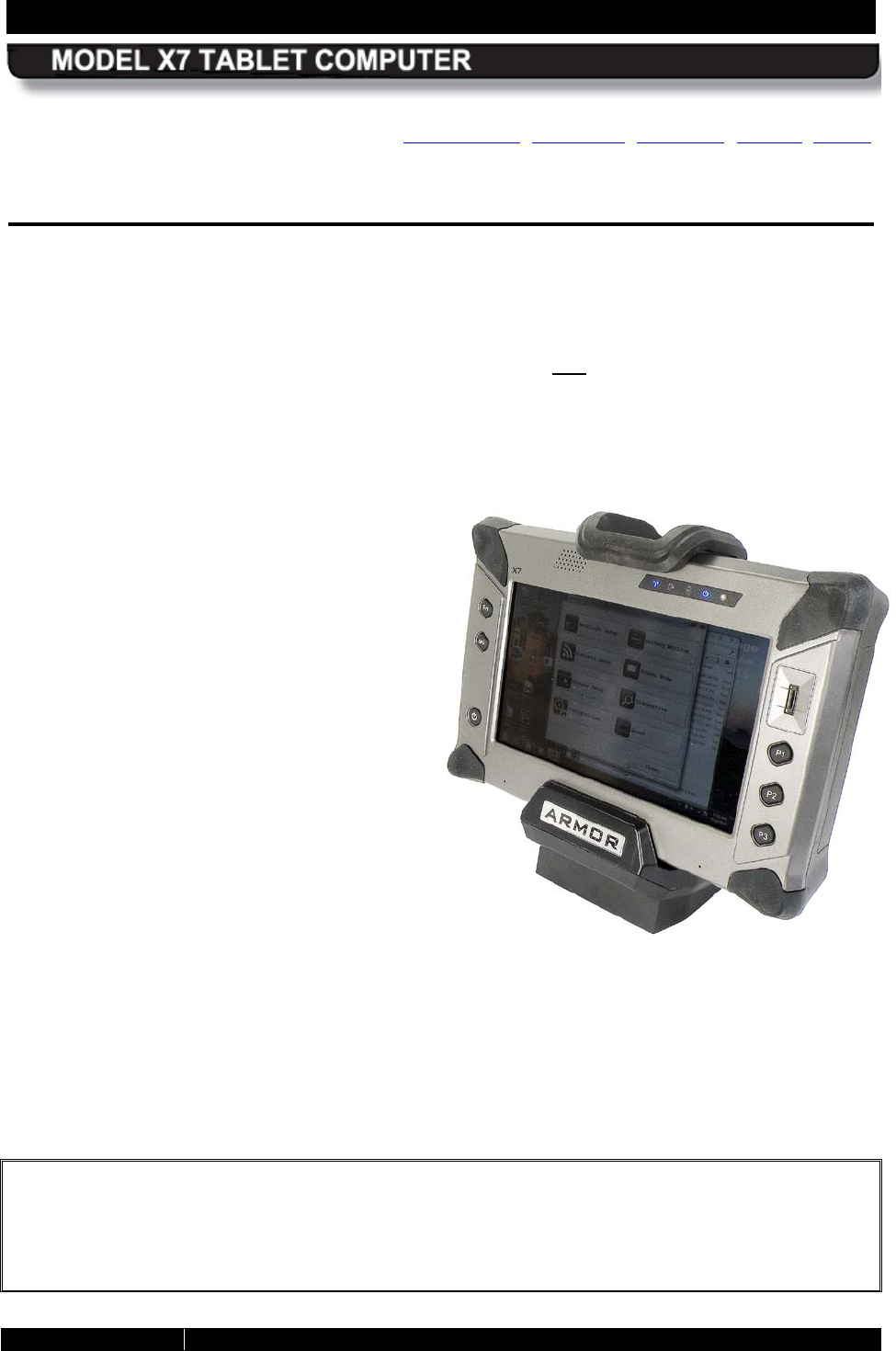
The ARMOR X7 ruggedized
tablet compu
ter can be
mounted in a vehicle dock or
desk docking station (shown
here in a desk dock).
SECTION 1 WELCOME AND INTRODUCTION PAGE 26
9711-26400-0001
EXPORT CONTROLLED – SEE PAGE 3
Rev A
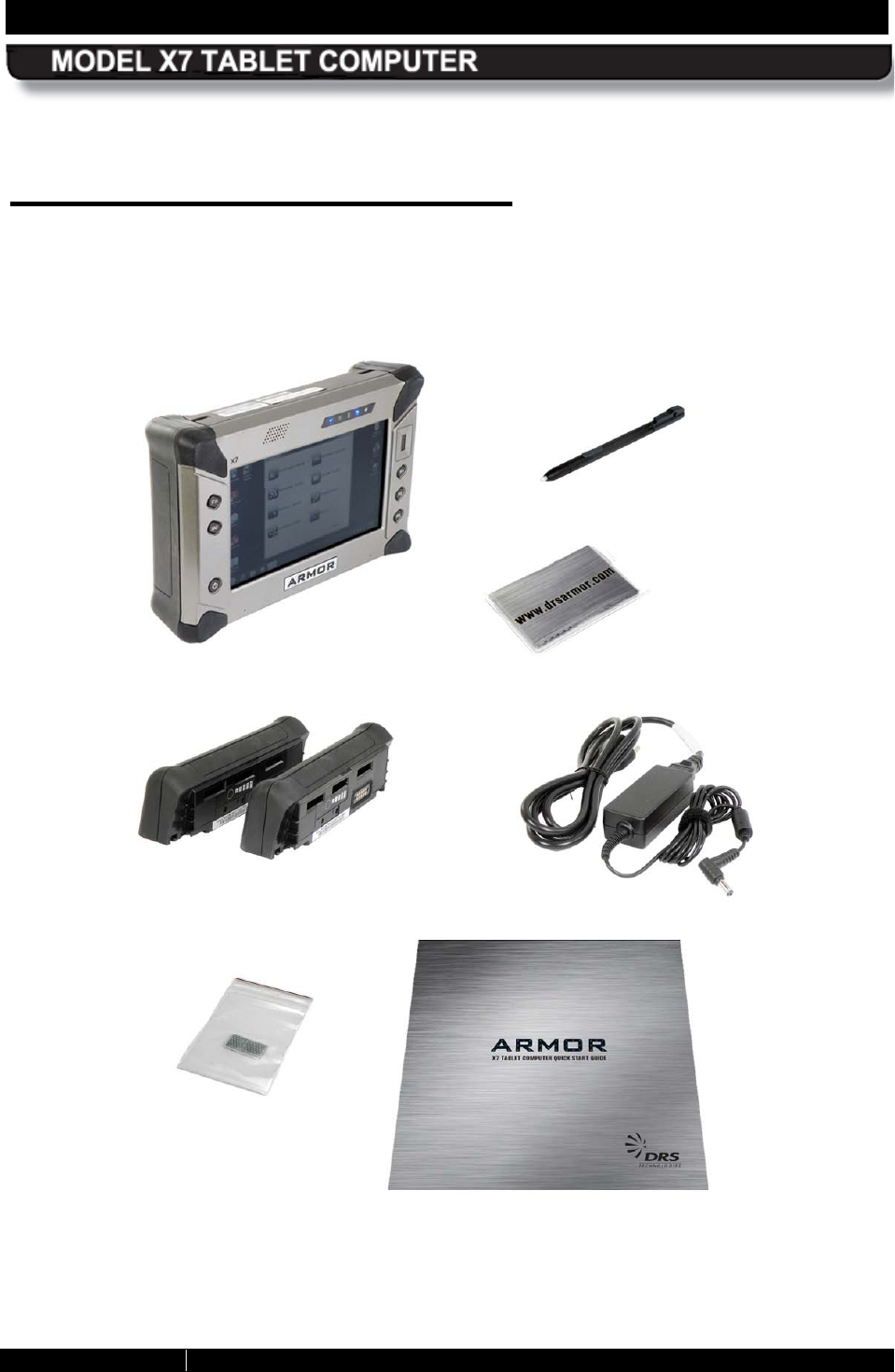
Your AR MOR X7 Purchase
Your purchase includes the components and accessories shown below. Please verify that all of
these items are present and in good condition. Contact your ARMOR X7 computer sales
representative if any item is missing or damaged.
Contact your ARMOR sales representative if any item is missing or damaged.
ARMOR X7 Included Components and Accessories
COMPUTER
AC ADAPTER
BATTERIES (2)
ACTIVE PEN
MICROFIBER
CLOTH
QUICK START GUIDE
THERMAL PADS

SECTION 1 WELCOME AND INTRODUCTION PAGE 27
9711-26400-0001
EXPORT CONTROLLED – SEE PAGE 3
Rev A
About This Guide
This user’s guide contains virtually all of the information required to setup and maintain your
ARMOR X7 tablet computer. However, should you need additional technical information,
please visit our web site at: www.drsarmor.com, or call DRS Technical Support toll-free at 1-
888-872-1100.
This guide is written for the Windows 7® operating system.
Viewing, Navigating, and Printing this Guide
This User’s Guide is installed on your ARMOR X7 computer in PDF format. It is primarily
designed for online viewing, but it can also be printed in 2-sided book format.
Double-click on the ARMOR X7 User’s Guide icon on the desktop to open the guide in your
Adobe® PDF Reader™. The latest version of Adobe PDF Reader is available for downloading
free from www.adobe.com.
While viewing this guide, you can click on any Figure or Table reference and on any blue
underlined text to navigate within the guide or to access resources on the Internet.
Some links may change color after the first access while others will not change colors. This is
due to the type of internal or external linking required.
Please Help Us Maintain Top Quality
Documentation
This guide was produced with the latest information available and verified for accuracy at the
time of its release. However, mistakes are still possible and product updates may supersede the
information in this guide.
We encourage you to contact DRS Technical Support toll-free at 1-888-872-1100 for information
on how to obtain the latest version of this document, or if you have corrections or suggestions to
improve this guide.

SECTION 1 WELCOME AND INTRODUCTION PAGE 28
9711-26400-0001
EXPORT CONTROLLED – SEE PAGE 3
Rev A
This Page Intentionally Left Blank
SECTION 2 LEARNING ABOUT YOUR ARMOR X7 PAGE 29
9711-26400-0001
EXPORT CONTROLLED – SEE PAGE 3
Rev A
Table of Contents List of Figures List of Tables Acronyms Glossary
2. LEAR NING AB OUT YOUR ARMOR X7
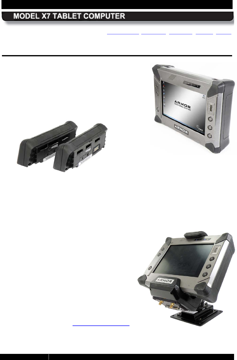
Rugged yet Stylish: The X7 is a tough, full-feature
small form factor tablet PC with built-in Wi-Fi® and
Bluetooth networking. Its compact size and low weight,
coupled with a high-contrast display for use in bright
sunlight, make it ideal for field use. In addition to being a
solid workhorse, your X7 looks good and feels good just
holding it in your hands.
Durable: Your X7 has an Ingress Protection Rating (IP) of 65. It can withstand a 6 foot drop
and still function. The X7 is specifically designed to support a full 8-hour shift operating on one
set of batteries. Its hot-swap battery access means you can change a battery at any time
without the need for tools and without having to power down the tablet.
Innovative and Flexible: The X7 tablet can
be used standing up, sitting down or mounted in a
vehicle. It has a dual mode Touch and Pen screen
supporting both finger navigation and detailed
graphic positioning using a pen or stylus. Your X7 is
ready for use anywhere, any time.
Expandable: The X7 can accommodate an
optional wireless wide area network (WWAN) card so
you can roam to your heart’s content even when
travelling in Europe or Asia, and it supports a GPS
satellite receiver that you can use to pinpoint your
location anywhere in the world. It even has a flexible
interface that allows for the use of other custom
cards and modules (refer to Flexspace™ Expansion
for a more detailed description of this capability).
SECTION 2 LEARNING ABOUT YOUR ARMOR X7 PAGE 30
9711-26400-0001
EXPORT CONTROLLED – SEE PAGE 3
Rev A
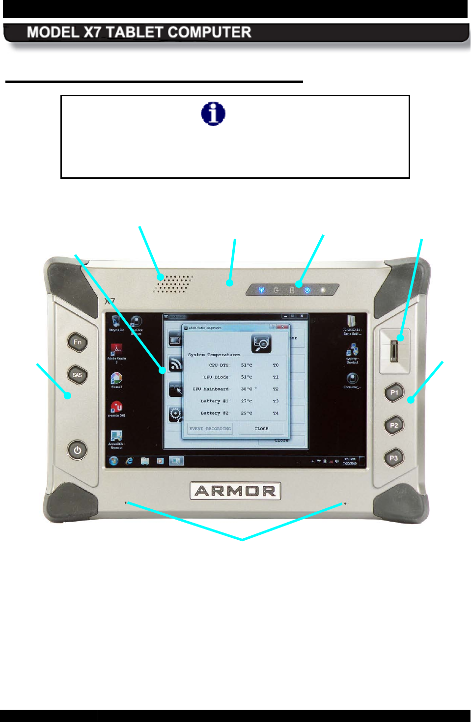
Front and Top Panel Features
NOTE
All references to front/back, top/bottom and left/right are relative
to the face-on view as shown in
Figure 1 .
Figure 1. ARMOR X7 Key Features – Front View
FINGERPRINT
SENSOR
HIGH
BRIGHTNESS
DUAL MODE
DISPLAY
WLAN / WWAN / GPS
ANTENNAS
NOISE CANCELLING
MICROPHONES
RIGHT
CONTROL
PANEL
INDICATOR
PANEL
LEFT
CONTROL
PANEL
SPEAKER
SECTION 2 LEARNING ABOUT YOUR ARMOR X7 PAGE 31
9711-26400-0001
EXPORT CONTROLLED – SEE PAGE 3
Rev A
Dis play
The X7 display is a high-brightness, high-contrast LCD display with anti-glare filtering that
ensures your screen can be clearly viewed even in bright sunlight. A replaceable screen
protector is attached at the factory to reduce glare and protect the touch screen surface.
The X7 is equipped with both an active pen (digitizer) screen and a touch screen. The pen
digitizer screen permits precise data entry and accurate handwriting conversion while the touch
screen provides quick and accurate operation using just a fingertip. A passive stylus (not
supplied) will provide even more precision with the touch screen. You can choose to operate
with both screens (Dual Mode) or with only one screen (Touch Only or Pen Only). Both screens
have the same clear, crisp viewing quality in any lighting situation.
In Dual Mode, the touch screen is enabled. However, if an active pen is detected with ½” of the
screen, the touch interface is turned off and active pen takes over. Switching between the two
screens is automatic and instantaneous.
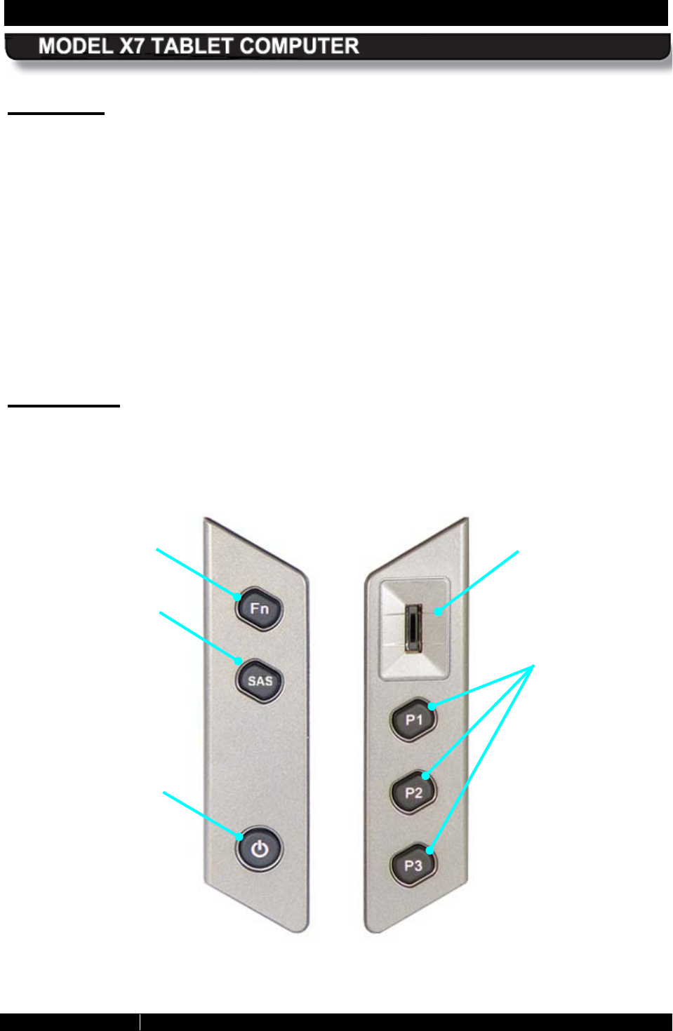
Controls
There are 6 push buttons and a fingerprint sensor on two control panels located on either side
of the X7 display (Figure 2). Each button has a built-in LED that varies in intensity with the
screen brightness. The following paragraphs describe the purpose of each control.
Figure 2. X7 Control Panels
FINGERPRINT
SENSOR
SECURITY ATTENTION
SEQUENCE (SAS)
BUTTON
POWER
BUTTON
FUNCTION (Fn)
BUTTON
PROGRAMMABLE
BUTTONS (PBs)
SECTION 2 LEARNING ABOUT YOUR ARMOR X7 PAGE 32
9711-26400-0001
EXPORT CONTROLLED – SEE PAGE 3
Rev A
Programmable B uttons (P B s ) P1, P2, P3
The PBs can be programmed to activate different functions such as controlling brightness,
changing volume level or activating an application with just a single press. These buttons are
preset to specific functions but you can change them to a different function. Refer to Buttons
Setup for information on current programming and how to change to other available options.
NOTE: The PB functions are only available while ARMORutils is running.
Each programmable button has a built-in LED that varies in intensity with the screen brightness.
Fingerprint S ens or (FPS )
The fingerprint sensor is used with security software to allow you to log into your account on this
computer or secure your access to specific applications and online websites. Refer to
TrueSuite™ Fingerprint Recognition Software for instructions on how to setup and use the FPS.
Fn (Function) B utton
This button is used with PBs P1, P2 and P3 (button “combos”) to activate three additional
functions. Press and release the Fn button and then press and release P1, P2 or P3 to activate
the combo function. Refer to Buttons Setup Dialog for information on how to program available
functions for each button and button combo.
S ecurity Attention S equence (S AS ) B utton
The SAS button is also known as the Windows Security Key button and the OEM Button.
Pressing this button invokes the CTRL-ALT-DEL command, which opens a menu on the
desktop. From this menu, you have the following options:
• Lock this computer
• Switch User
• Log off
• Change password
• Start Task Manager
Power B utton
The Power button is primarily used to turn the computer on, but it also performs other functions
when the computer is running and when the computer is in sleep or hibernate mode.
lists the default actions of the power button when you first receive your X7.
NOTE: To turn the computer off, refer to the instructions in Putting the Computer into Hibernate
Mode and Emergency Shutdown.
SECTION 2 LEARNING ABOUT YOUR ARMOR X7 PAGE 33
9711-26400-0001
EXPORT CONTROLLED – SEE PAGE 3
Rev A
Table 1. Initial Power Button Actions
Operating State
Power Button Action
Result
Computer powered off
Press and hold for at least
1 second and then release
Computer turns on and boots up
into new Windows session.
Computer powered on and
awake
Press and release
Computer goes into Sleep mode
and saves your current session
to memory.
Computer in Sleep mode
(powered on)
Press and hold for at least
1 second and then release
Computer wakes up and
restores your current session.
Computer in Hibernate mode
(powered off)
Press and hold for at least
1 second and then release
Computer turns on and restores
your previous session.
Computer powered on and
awake
To shut down the
computer normally, select
Start
à
Shut down from
the Windows desktop.
The computer will perform a
normal shutdown.
Computer powered on and
awake
Press and hold for 5 or
more seconds (emergency
shutdown)
Computer shuts down
immediately and does not save
your session.
Computer off and batteries
exhausted
Press and hold for at least
1 second and then release
Charging/Fault indicator blinks 5
times to indicate batteries
exhausted.
Changing the Default Power B utton Action
When you receive your X7, the default action for pressing the Power button during normal
operation is to put the computer in Sleep mode. You can change the default action of the Power
button through the Power Options settings in Windows Control Panel. The actions that are
available are: Do Nothing, Sleep, Hibernate or Shut Down. Refer to Changing the Power Button
Default Action.
NOTE: This change will only affect the action of the Power button during the operating state; it
will still work the same as described in Table 1 when the computer is powered off or is in sleep
or hibernate mode.
SECTION 2 LEARNING ABOUT YOUR ARMOR X7 PAGE 34
9711-26400-0001
EXPORT CONTROLLED – SEE PAGE 3
Rev A
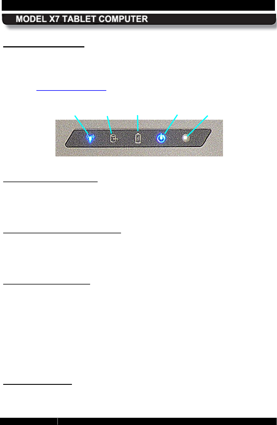
Indicator Panel
There are 4 LED status indicators located on the indicator panel at the upper right of the X7
display, as shown in Figure 3 (NOTE: The fifth object to the far right on the panel is the ambient
light sensor (ALS), not an LED). The intensity of the status indicators will vary as the screen
brightness is varied. The functions of these indicators and the function of the ALS are described
below. See Indicator State Summary for a complete description of each indicator state.
Figure 3. X7 Indicator Panel
Wireles s Activity Indicator
A blue LED that is on intermittently whenever the Wi-Fi, WWAN or Bluetooth wireless radio is
connecting. The indicator will be on steady if either the WLAN or WWAN radio is connected to a
network. For Bluetooth, the indicator will only be on when data is being transmitted to a
peripheral such as a printer, scanner or USB hub.
S torage Device Activity Indicator
A blue LED that is on intermittently whenever a storage device is being accessed. Storage
devices include the embedded mSATA drive and an optional SD flash memory card and/or an
optional 1.8 solid-state hard drive. (NOTE: The mSATA drive is an integral part of the X7
circuitry and is not physically accessible by the user).
Charging/Fault Indicator
This amber/red LED has the following conditions:
• Off when the tablet is powered up and external power is not connected.
• On steady amber when external power is connected and batteries are fully charged.
• Flashing amber at a 1-second rate when either or both batteries are charging.
• On steady red if a power system error occurs, such as an overvoltage, undervoltage or
overcurrent condition or a battery failure.
NOTE: If power is off and the batteries are exhausted (depleted), pressing the Power button will
cause the Charging/Fault indicator to flash 4-5 times, indicating that you need to connect
external power and recharge the batteries.
Power On Indicator
A blue LED that is on steady whenever power is applied to the ARMOR X7 and is off when
power is shut down.
WIRELESS
STORAGE
CHG/FLT
POWER
ALS

SECTION 2 LEARNING ABOUT YOUR ARMOR X7 PAGE 35
9711-26400-0001
EXPORT CONTROLLED – SEE PAGE 3
Rev A
Ambient Light Sens or (ALS )
When the X7 display is in automatic brightness mode, the ALS senses changes in surrounding
light levels and adjusts the display brightness and indicator light levels accordingly. If the
surrounding light level increases, the display and indicator brightness will increase
proportionally; if the light level decreases, the display and indicator brightness will decrease
proportionally.
S peaker
A single high-volume speaker is located on the top left of the front panel, as
shown in
Figure 1. Provisions for plugging in a headset, external speakers or an external microphone are
provided only with an optional desk dock or vehicle dock.
Noise Cancelling S tereo Microphones
Two noise-canceling microphones are located at the bottom of the front panel. These
microphones support simultaneous analog and 2-channel digital array recording
SECTION 2 LEARNING ABOUT YOUR ARMOR X7 PAGE 36
9711-26400-0001
EXPORT CONTROLLED – SEE PAGE 3
Rev A
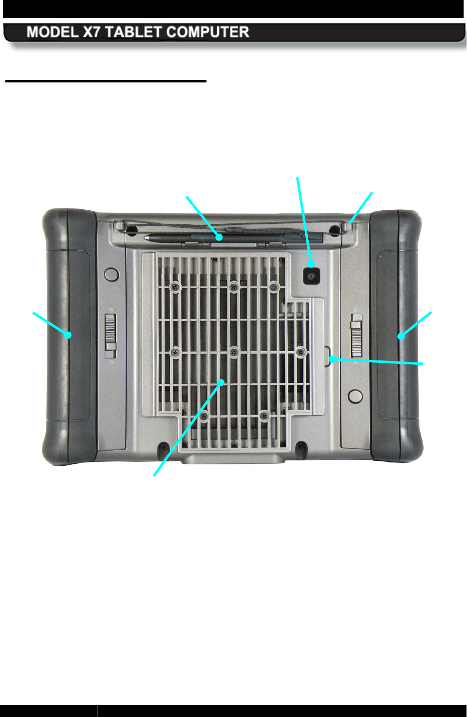
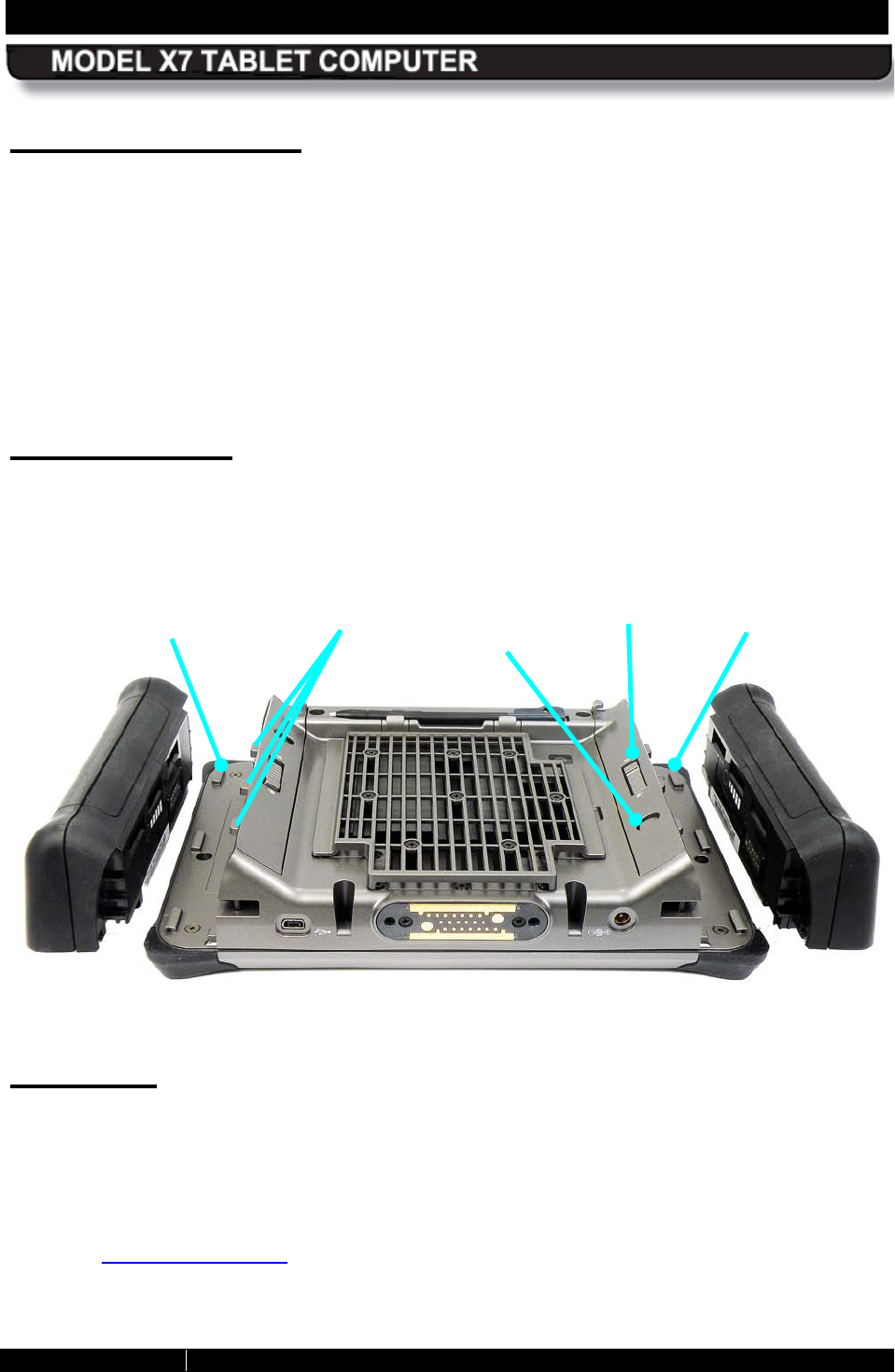
R ear Panel Features
The rear panel of the X7 houses a built-in webcam, a cooling register, two battery bays and a
removable cooling register/cover that provides access to installed radio modules, a SIM card
socket, and a micro SD socket. A slot for the active pen is built into the back panel with posts to
secure the lanyard.
Figure 4. Key Features - Rear Panel
HEAT SHIELD AND COOLING
REGISTER
BATTERY
#2
BATTERY
#1
WEBCAM
ACTIVE
PEN WITH LANYARD
LANYARD
POST (X2)
COVER
REMOVAL
SLOT
SECTION 2 LEARNING ABOUT YOUR ARMOR X7 PAGE 37
9711-26400-0001
EXPORT CONTROLLED – SEE PAGE 3
Rev A
Cooling R egister
ARMOR computers are designed to operate in wet and dirty environments under extreme
temperatures. Because the tablet is sealed against contamination, it incorporates passive
cooling which channels the internal heat to the cooling register at the back of the unit. The
cooling register dissipates the heat to the atmosphere and normally feels only warm to the
touch. However, under heavy use, the register can become hot to the touch and, as a safety
and comfort measure, a plastic heat shield covers the register to prevent direct contact.
The cooling register also acts as a cover for a sealed compartment which provides access to
the wireless radio cards, a SIM card socket, a micro-SD socket and any optional or custom
cards.
B attery Bays
Your X7 is shipped with two custom designed batteries that are installed in bays on either side
of the X7, as shown in Figure 5. In addition to supplying power to the computer, the X7 batteries
also act as the handles or grips for the computer.
Figure 5. X7 Battery Bays
Webcam
Your X7 has a built-in 2 megapixel camera located on the back side of the unit (see Figure 6).
The camera is equipped with an autofocus lens and can be used to capture still images or
movies, or to scan barcodes. The camera saves still images in JPEG format at 1280x1024,
800x600 and 640x480 pixel resolutions. Movies are saved in Windows Media Video (.wmv)
format.
Refer to Using the Webcam for instructions on capturing still images and video, and for
scanning bar codes.
BATTERY BAY
#2
BATTERY BAY
#1
BATTERY
LATCH
BATTERY
LOCK
BUTTON
BATTERY
RELEASE
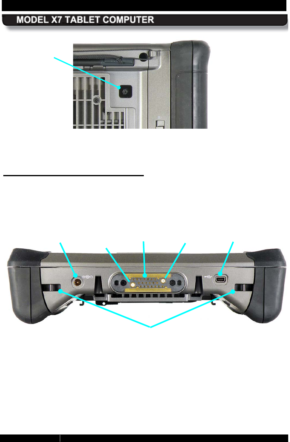
SECTION 2 LEARNING ABOUT YOUR ARMOR X7 PAGE 38
9711-26400-0001
EXPORT CONTROLLED – SEE PAGE 3
Rev A
Figure 6. X7 Webcam
B ottom Panel Features
The bottom panel houses a DC power input jack, a mini-USB connector and a 20-pin docking
connector. The docking connector contains two RF ports to connect the X7 to external GPS and
wireless antennas.
Figure 7. Key Features – Bottom Panel
DC POWER
INPUT JACK
DOCKING
CONNECTOR
MINI USB
CONNECTOR
GPS ANTENNA
CONNECTOR
WIRELESS
ANTENNA
CONNECTOR
WEBCAM
LENS
ACCESSORY
MOUNTING POINTS
(2 ON TOP PANEL)
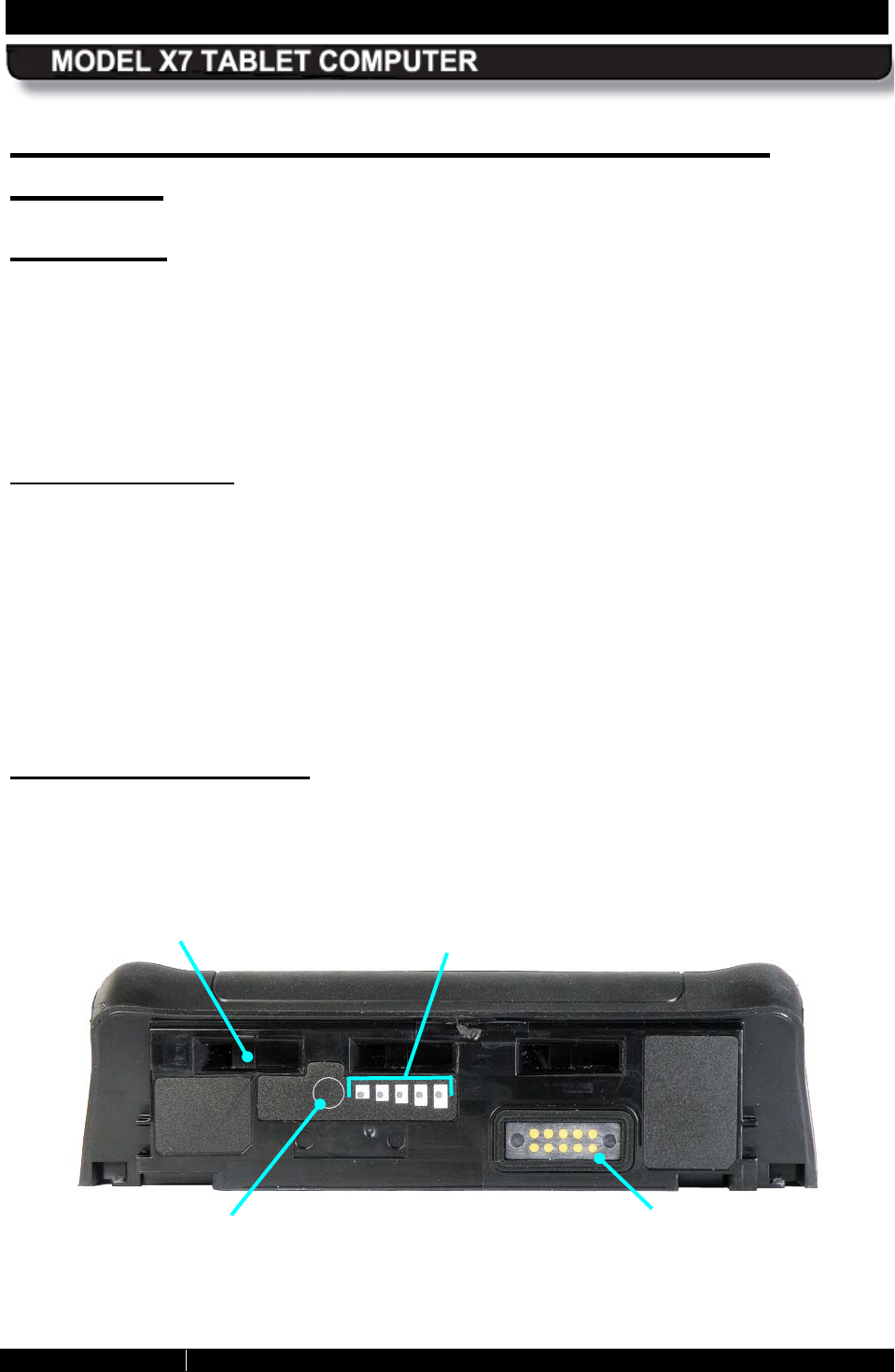
SECTION 2 LEARNING ABOUT YOUR ARMOR X7 PAGE 39
9711-26400-0001
EXPORT CONTROLLED – SEE PAGE 3
Rev A
Included Components, Accessories and
S upport
B atteries
Your X7 batteries are high efficiency lithium-ion batteries that are “hot swappable.” That is, if
you have two batteries installed, you can replace one battery while the computer operates on
the other battery. With this capability, you do not have to shut down the computer or interrupt
your current operating session in order to replace a battery.
The batteries come in two different capacities: 2950 mAh (standard) and 5900 mAh (high-
capacity).
B attery Des cription
Figure 8 shows a single X7 battery. Each battery has three locking slots that fit into three
corresponding hooks on the battery latch. A multi-LED battery charge indicator, or “fuel gauge”
is located next to the fuel gauge button. The fuel gauge consists of 5 LEDs and each LED
represents approximately 20% of the total charge of the battery as follows:
LED #5 - 80-100% On steady
LED #4 - 60-79% On steady
LED #3 - 40-59% On steady
LED #2 - 21-40% On steady
LED #1 - 00-10% Flashing (far left LED)
Ac tivating the Fuel Gauge
The fuel gauge indicators are not visible when the battery is installed in the computer. When a
battery is disconnected, you can press the fuel gauge button to activate the LEDs and check
the current charge level.
Figure 8. ARMOR X7 Battery
FUEL GAUGE
BUTTON
FUEL GAUGE
BATTERY
CONNECTOR
1 2 3 4 5
LOCKING SLOTS (3)
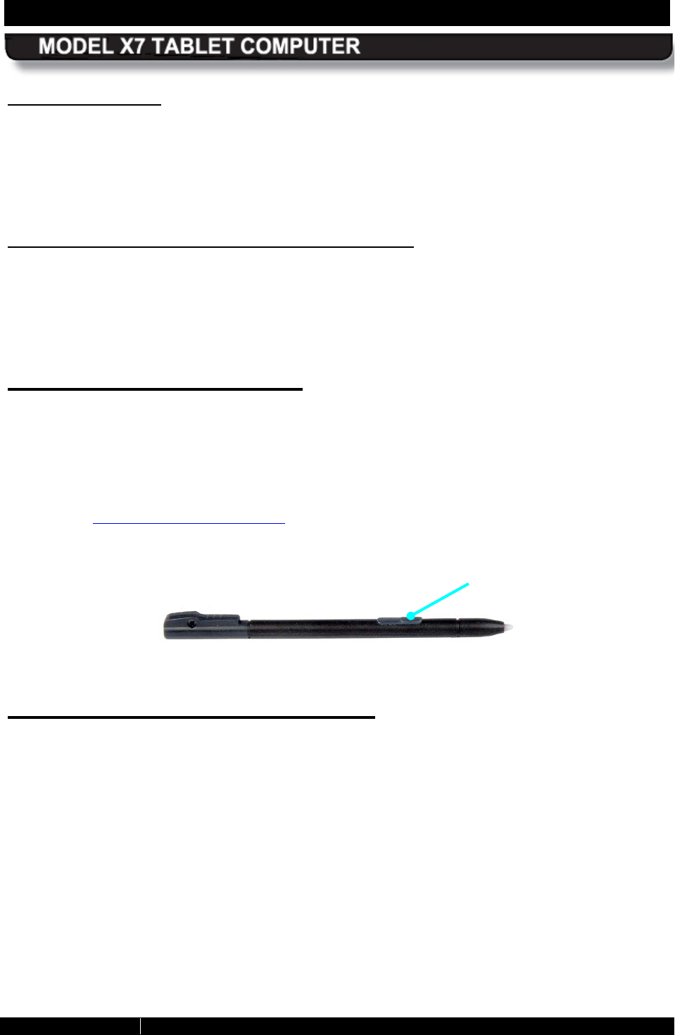
SECTION 2 LEARNING ABOUT YOUR ARMOR X7 PAGE 40
9711-26400-0001
EXPORT CONTROLLED – SEE PAGE 3
Rev A
“ S mart” B atteries
Your X7 batteries have built-in “smart” technology to monitor their charging functions and
internal conditions. These batteries are self-calibrating and self-regulating. Should a problem
occur, even a short circuit, the X7 battery will disconnect itself from the computer to prevent any
damage. Since the batteries are literally the handles for the X7, you can keep a defective
battery in place until you obtain a replacement.
S tandard B atteries vs . High-Capacity Batteries
Depending on your purchase, your X7 came with either two standard batteries or two high-
capacity batteries. A single standard battery has a capacity of 2950 milli-ampere hours (mAh)
and a high-capacity battery has a capacity of 5900 mAh.
Table 33 lists the charging times and Table 35 lists the operating times for both battery types.
Active P en with T ether
The active pen (P/N 0000F50872-0000) that comes with your X7 (Figure 9) has circuitry in the
tip that interacts with the digitizer assembly built into the tablet display. The digitizer detects the
pen tip close to the screen and activates certain functions like steering the pointer or performing
a right click action if the pen is allowed to hover for a few seconds.
The pen also has a side button that can be programmed for a number of different functions
(refer to the Pen Tablet Properties Utility). Its default function is Right-Click. The pen is stored in
the tablet’s carrying handle and is secured to the handle by a string tether.
Figure 9. The ARMOR X7 Pen
AC Adapter and Power Cord
Included with your ARMOR X7 is a +19 VDC ± 5%, 2 amp AC power adapter, or “AC Adapter”
(P/N 0000F50874-0000). This external DC power supply can be plugged in to any 100-240
VAC outlet and is used to recharge your computer’s batteries and provide power to the
computer without draining the batteries.
A North American AC power cord (P/N 0000F50076-0000) is standard, but a European power
cord (0000F50076-0002) and a UK power cord (0000F50076-0001) are also available.
SIDE BUTTON
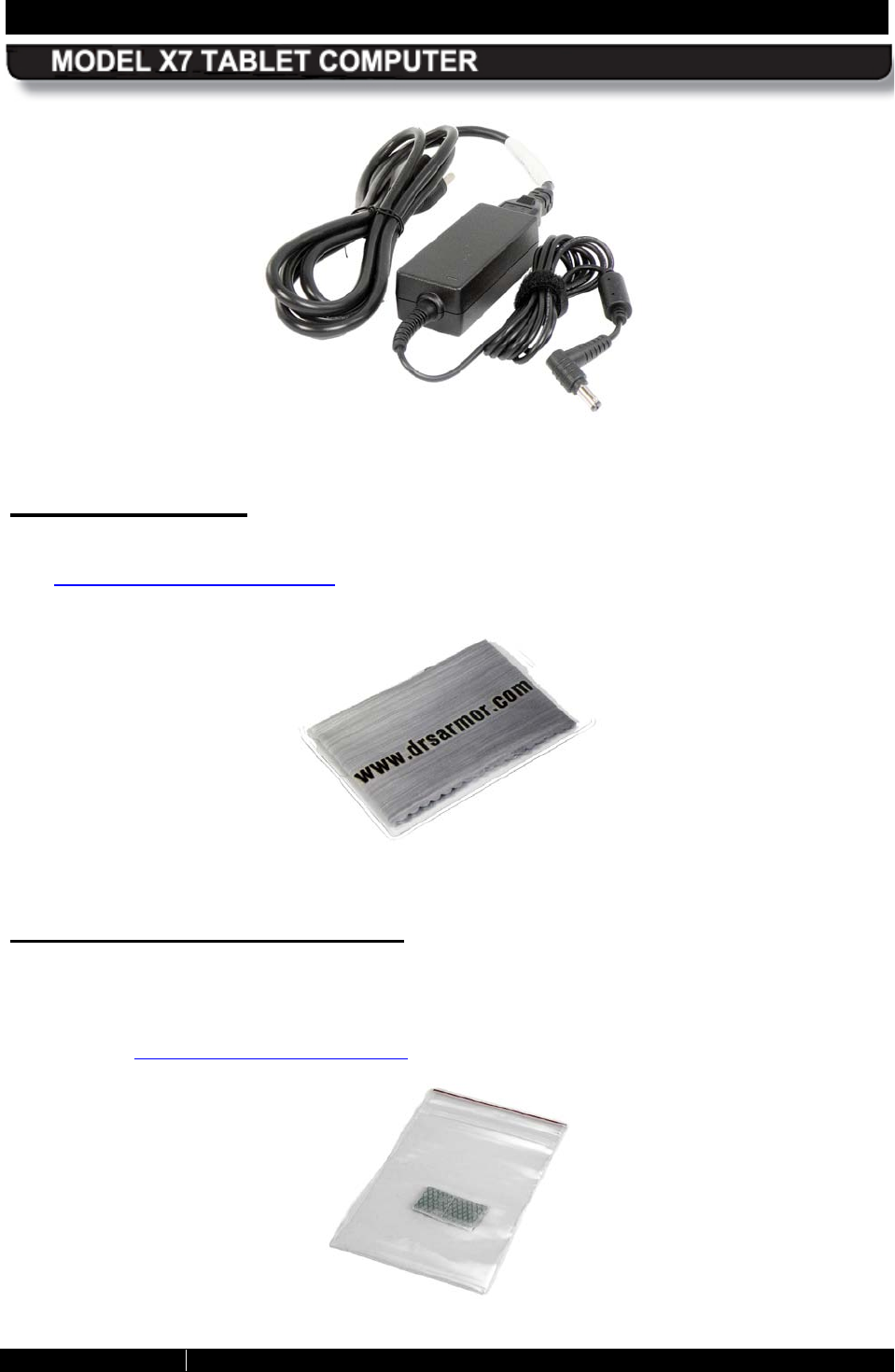
SECTION 2 LEARNING ABOUT YOUR ARMOR X7 PAGE 41
9711-26400-0001
EXPORT CONTROLLED – SEE PAGE 3
Rev A
Figure 10. X7 AC Adapter
AR MOR C loth
This microfiber cloth is specially designed to clean the display screen of dust and fingerprints.
See Caring For the Display Screen for important information about using this cloth with the X7
display.
Figure 11. ARMOR Microfiber Cleaning Cloth
Thermal Transfer Pads
Two thermal transfer pads are included with your X7 in case the original pads are damaged
while removing the rear cooling register/cover to install a SIM or SD card, or to change the solid-
state drive. These pads should only be replaced if the original pads are torn during cover
removal (see Maintaining Your ARMOR X7 for cover removal and replacement instructions).
Figure 12. Thermal Transfer Pads
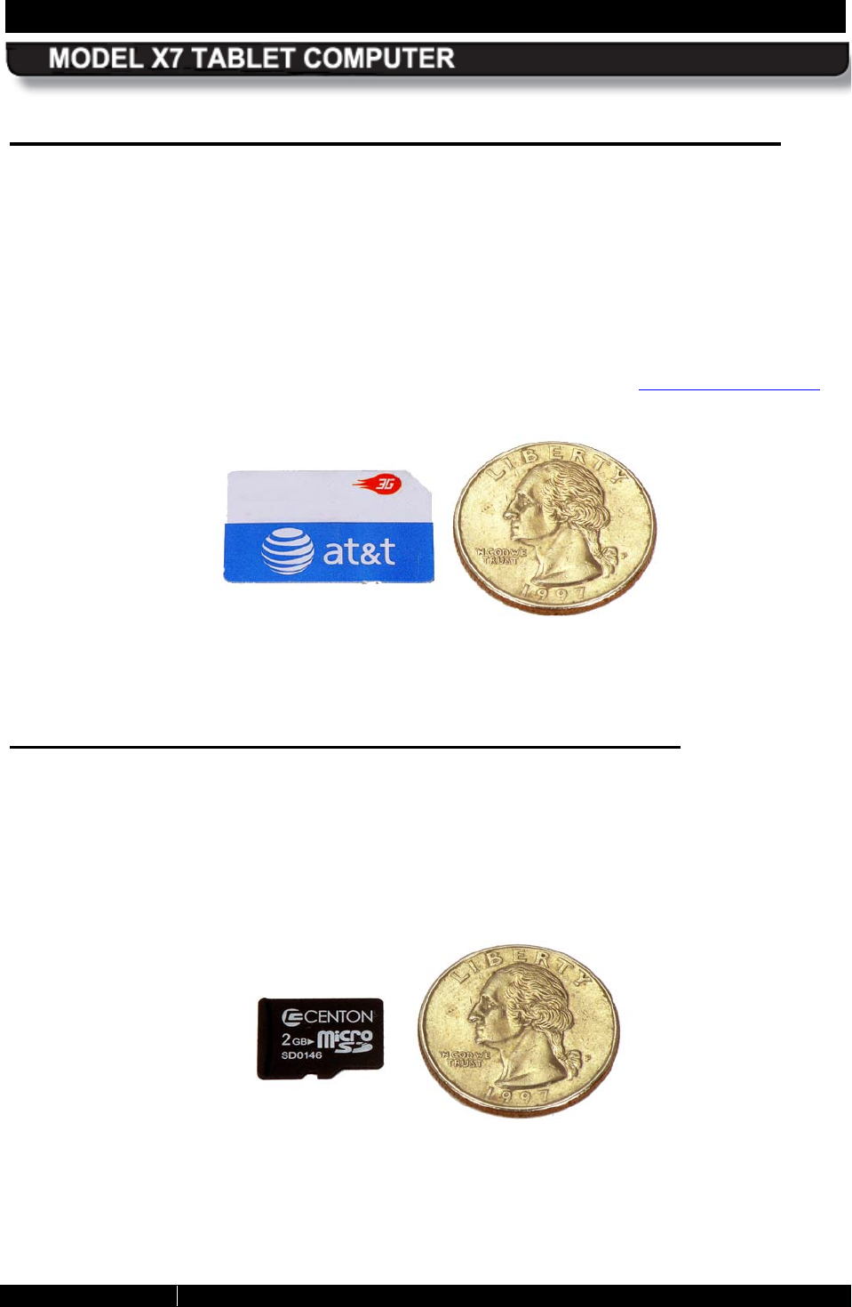
SECTION 2 LEARNING ABOUT YOUR ARMOR X7 PAGE 42
9711-26400-0001
EXPORT CONTROLLED – SEE PAGE 3
Rev A
S ubscriber Identity Module (S IM) Card S upport
The X7 is equipped with a SIM card socket for use with some WWAN network providers. A SIM
card is a small electronic card that contains your GSM subscriber ID, billing information, and
network permissions. The card allows you to easily transport your subscriber information to
another computer or subscriber device. SIM cards are used by CSM-based networks such as
AT&T® and T-Mobile®, as well as most European WWAN providers.
Figure 13 shows the size of the SIM card compared to a quarter (NOTE: The SIM card shown is
blank - a valid card has the customer’s account code printed on it).
You must have a SIM card installed in order to use your Gobi radio to connect to a GSM WWAN
network in Europe and to certain providers in the United States. Refer to Installing a SIM Card.
Figure 13. SIM Card
S ecure Digital (S D) Card R eader S upport
The ARMOR X7 also provides a card reader for a micro SD or SDHC card in capacities of 8, 16,
or 32 GB. These cards are about half the size of a SIM card and are used as removable flash
drives. The socket for the micro SD card is located inside the X7 case, as shown in Figure 94.
The Windows operating system recognizes the card as a removable drive, just like a USB
memory stick.
Figure 14. Micro SD Card

SECTION 2 LEARNING ABOUT YOUR ARMOR X7 PAGE 43
9711-26400-0001
EXPORT CONTROLLED – SEE PAGE 3
Rev A
Trusted Platform Module (TPM) Support
The X7 supports the Infineon SLB 9635 TPM controller module. This module meets the
requirements of the Trusted Computing Group (TCG) Trusted Platform Module Specification
1.2. The TPM module is connected to the low pin count (LPC) bus.
For more information on TPM capabilities with the ARMOR X7, contact DRS Tactical Systems,
Inc. toll free at 1-800-872-1100.
Flexspace™ E xpans ion
Your ARMOR X7 contains special areas with flexible I/O interfaces that can accommodate
custom cards or modules. These special areas are referred to as “flexspace.”
There are two flexspace locations in the ARMOR X7: An internal flexspace located directly
under the cooling register (the area bounded in red in Figure 15), and a special battery adapter
flexspace that takes the place of the right-side battery, as shown in Figure 16.
Internal Flexs pace
The internal flexspace accepts a custom circuit board or module that connects to the X7 using
one of two different interface adapters: mini PCIe or PCI/USB. The example in Figure 15 shows
a WWAN card and SIM socket module connected with the mini PCIe adapter. Each interface
adapter plugs into a 60-pin flexspace connector which is mounted on the motherboard.
The internal flexspace provides the following voltages and signals: +5VDC @ 1A, 3.3VDC @
1A, two USB 2.0 ports, four GPIO discretes to the EC processor, one PCI Express channel, one
RS-232 serial port with hardware handshake and connections for a microphone and stereo
headphone. Two spare pins for future use are also provided.
The cooling register/cover can be modified to accommodate cards and modules requiring
thicker cross-sections.
B attery Adapter Flexs pace
The battery adapter flexspace can house a custom module or antenna, or it can provide
additional external connectors as shown in the concept model in Figure 16.
The battery adapter flexspace provides the following voltages and signals: +5VDC @ 1A,
3.3VDC @ 1A, two USB 2.0 ports and two GPIO discretes to the EC processor.
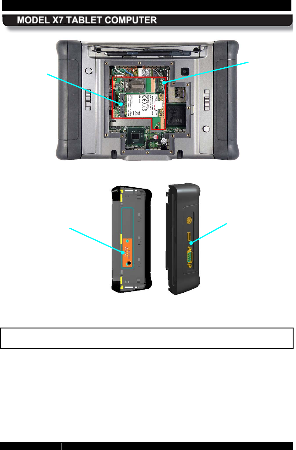
SECTION 2 LEARNING ABOUT YOUR ARMOR X7 PAGE 44
9711-26400-0001
EXPORT CONTROLLED – SEE PAGE 3
Rev A
Figure 15. X7 Internal Flexspace
Figure 16. ARMOR X7 Battery Adapter Flexspace Concept
For more information on the X7’s expansion capabilities, contact DRS Tactical Systems,
Inc. toll free at 1-800-872-1100.
EXPANSION
CONNECTOR
FLEXSPACE
ADAPTER
WITH
CUSTOM I/O
CONNECTOR
MODULE
INTERFACE
ADAPTER
FLEXSPACE
AREA
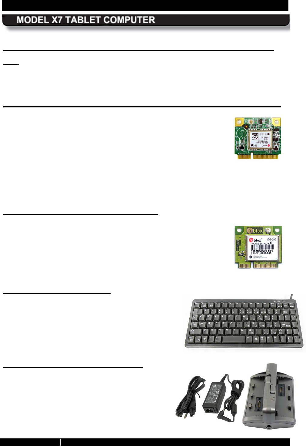
SECTION 2 LEARNING ABOUT YOUR ARMOR X7 PAGE 45
9711-26400-0001
EXPORT CONTROLLED – SEE PAGE 3
Rev A
Optional Add-ons and Accessories for Your
X7
The following add-ons and accessories extend the capabilities of the X7 or make it easier to
use.
Gobi® Wireless Wide Area Network (WWAN) Card
We offer the Gobi 2000 WWAN card. This wireless networking device
communicates over cell phone networks and can provide internet or
company-specific coverage while on the road or in areas that don’t
provide Wi-Fi access. It can be used in the US or overseas. Adding
WWAN service to your imbedded Wi-Fi capability means you have 24/7
connection to the internet virtually anywhere in the world. A
complementary copy of the Sierra® OneClick Internet Connection
Manager software is provided with this card.
Please contact DRS Tactical Systems toll free at 1-888-872-1100 for information about
purchasing and installing this card.
u-blox® GPS R eceiver Card
The u-blox GPS receiver is capable of downloading position data from
the GPS or Galileo satellite networks and enables you to pinpoint your
position anywhere in the world to within 2 meters. A complementary copy
of u-blox u-center™ GPS software is provided with this card.
Please contact DRS Tactical Systems toll free at 1-888-872-1100 for
information about purchasing and installing this card.
Compact K eyboard
A reduced-size USB keyboard (P/N 0000-16200-0000)
is available for use with the ARMOR X7 computer. The
keyboard is approximately half the size of a standard
keyboard and can be connected directly to the X7 using a
mini-USB adapter (nor supplied) or to a desk docking
station to conserve space on a table or desktop.
E xternal B attery C harger
A two-bay battery charger (P/N 9025F26500-1000) is
available for faster and more convenient battery
charging. Each battery bay has a charging time of
approximately 2.5 to 4 hours, depending on battery
type. The external charger is also handy for recharging
spare batteries and batteries kept in storage. A
19VDC, 40W AC adapter is included.

SECTION 2 LEARNING ABOUT YOUR ARMOR X7 PAGE 46
9711-26400-0001
EXPORT CONTROLLED – SEE PAGE 3
Rev A
Mini-USB Adapter
This USB to mini-USB adapter (P/N 0000F50015-0000) is available to
adapt the X7 mini-USB port to a standard USB cable or flash drive
connector.
D-R ing S et
This D-ring set (DRS P/N 9850F51031-0000) contains four D-rings that
clip to accessory mounting points on the top and bottom panels of the X7
(see Installing the Optional D-Rings). The D-Rings are constructed of
super-tough reinforced plastic that can support up to 43 pounds each.
With these D-Rings, you can attach your own carrying handle, shoulder
strap or other accessory.
S c reen P rotector
A flexible but tough screen protector is available that reduces glare and protects the touch
screen surface from wear and scratching. It is also resistant to a wide variety of toxic chemicals
including acetone, toluene, ethyl acetate, gasoline and concentrated hydrochloric acid. NOTE:
This screen protector may slightly reduce outdoor viewability.
Screen protectors are available in a package of 5 (DRS P/N 9850F48847-0007).
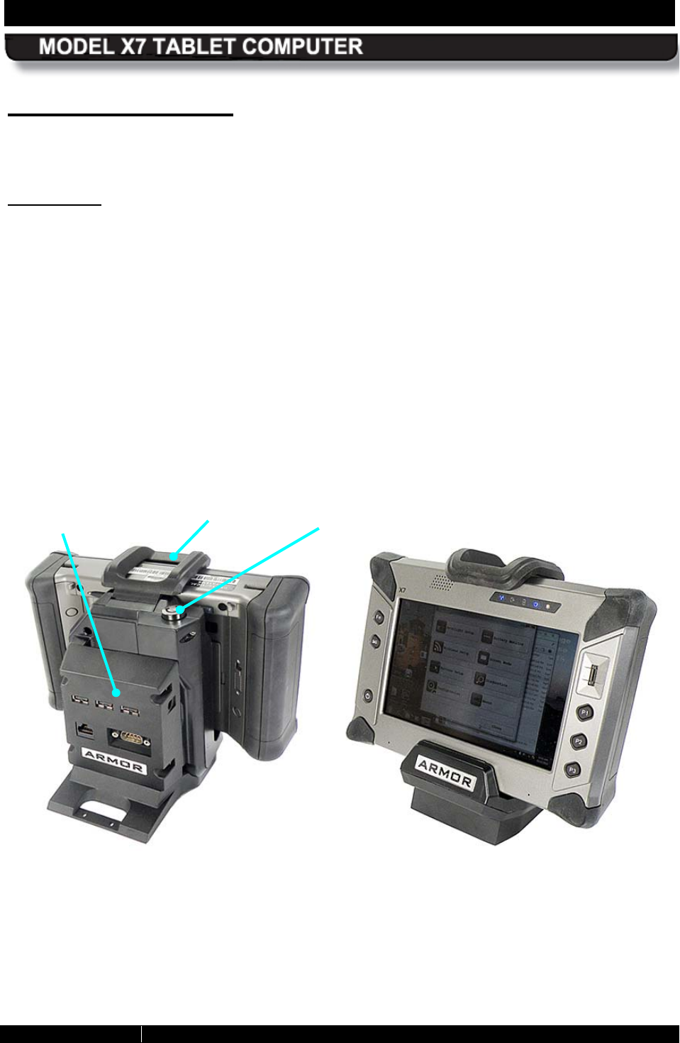
SECTION 2 LEARNING ABOUT YOUR ARMOR X7 PAGE 47
9711-26400-0001
EXPORT CONTROLLED – SEE PAGE 3
Rev A
Docking S tations
There are a number of new docking stations available to support and enhance the X7, either for
the desktop or for use in a vehicle.
Desk Dock
The X7 desk dock is designed to fit on your desktop without taking up a lot of space. It is made
of light-weight but rugged plastic. The removable breakout box has connectors for 3 USB ports,
an RJ45 Ethernet port, an RS-232 serial port and a DC power input jack. The breakout box also
has internal provisions for two GPIO ports.
The breakout box plugs into the dock base and is mounted to the back of the dock with four
socket-head screws. If desired, it can be removed and remoted away from the desktop with a
cable.
The X7 tablet is held in place with a spring-loaded top clamp that can be locked with a key. Two
holes are provided in the back of the base to secure the dock to the working surface if desired.
Figure 17. X7 Desk Dock
TOP CLAMP
CLAMP RELEASE
AND KEY LOCK
BREAKOUT
BOX
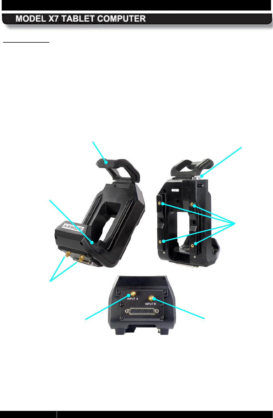
SECTION 2 LEARNING ABOUT YOUR ARMOR X7 PAGE 48
9711-26400-0001
EXPORT CONTROLLED – SEE PAGE 3
Rev A
Vehicle Dock
The X7 vehicle dock (P/N 9800F26300-0000) is made of UV-resistant high-impact plastic that
weighs less than 2 lbs. It is designed to be attached to any mount that accepts the Video
Electronics Standards Association (VESA) 75 mm hole pattern. The X7 dock is shown in
Figure 18. This dock has two RF connectors that are used to connect external GPS and
wireless antennas.
The top clamp mechanism that holds the X7 in place can withstand over 50,000 latch/unlatch
cycles and can be locked with a key to prevent tablet removal. The X7 tablet slips easily into the
dock and can be inserted and latched with one hand. The floating docking connector is field-
replaceable.
Figure 18. X7 Vehicle Dock
FINGERPRINT
SENSOR (FPS)
TOP CLAMP
MOUNTING
POINTS
EXTERNAL
ANTENNA
CONNECTORS
CLAMP RELEASE
AND KEY LOCK
DOCKING
CRADLE
GPS
ANTENNA
CONNECTOR
WIRELESS
ANTENNA
CONNECTOR
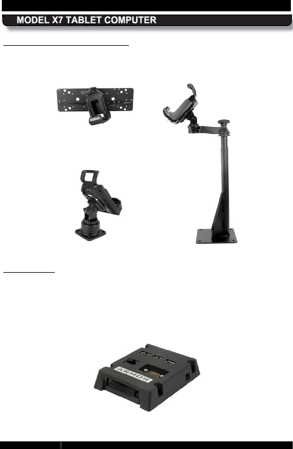
SECTION 2 LEARNING ABOUT YOUR ARMOR X7 PAGE 49
9711-26400-0001
EXPORT CONTROLLED – SEE PAGE 3
Rev A
Vehicle Dock Mounting Solutions
The X7 vehicle dock is rugged and light weight and can be adapted to just about any mounting
situation from console and dashboard installation to bulkhead and cab roof installation. Figure
19 shows some sample mounting solutions. Other types are available.
Figure 19. Examples of X7 Vehicle Dock Mounting Solutions
B reakout Box
The X7 breakout box (P/N 9800F26600-0000) is used with both the desk dock and the vehicle
dock. When used with the desk dock, it is plugged into a connector in the base of the desk dock
and secured to the back with four hex screws (see Figure 17). In a vehicle installation, the
breakout box is mounted away from the dock and connected by a 6 ft 25-pin cable to the
connector on the bottom of the dock.
The breakout box provides connections for 3 USB ports, an RJ45 Ethernet port, an RS-232
serial port and a DC power input jack. Two internal GPIO ports are also provided.
Figure 20. X7 Breakout Box
OVERHEAD
MOUNT
FLOOR
MOUNT
UNIVERSAL
MOUNT
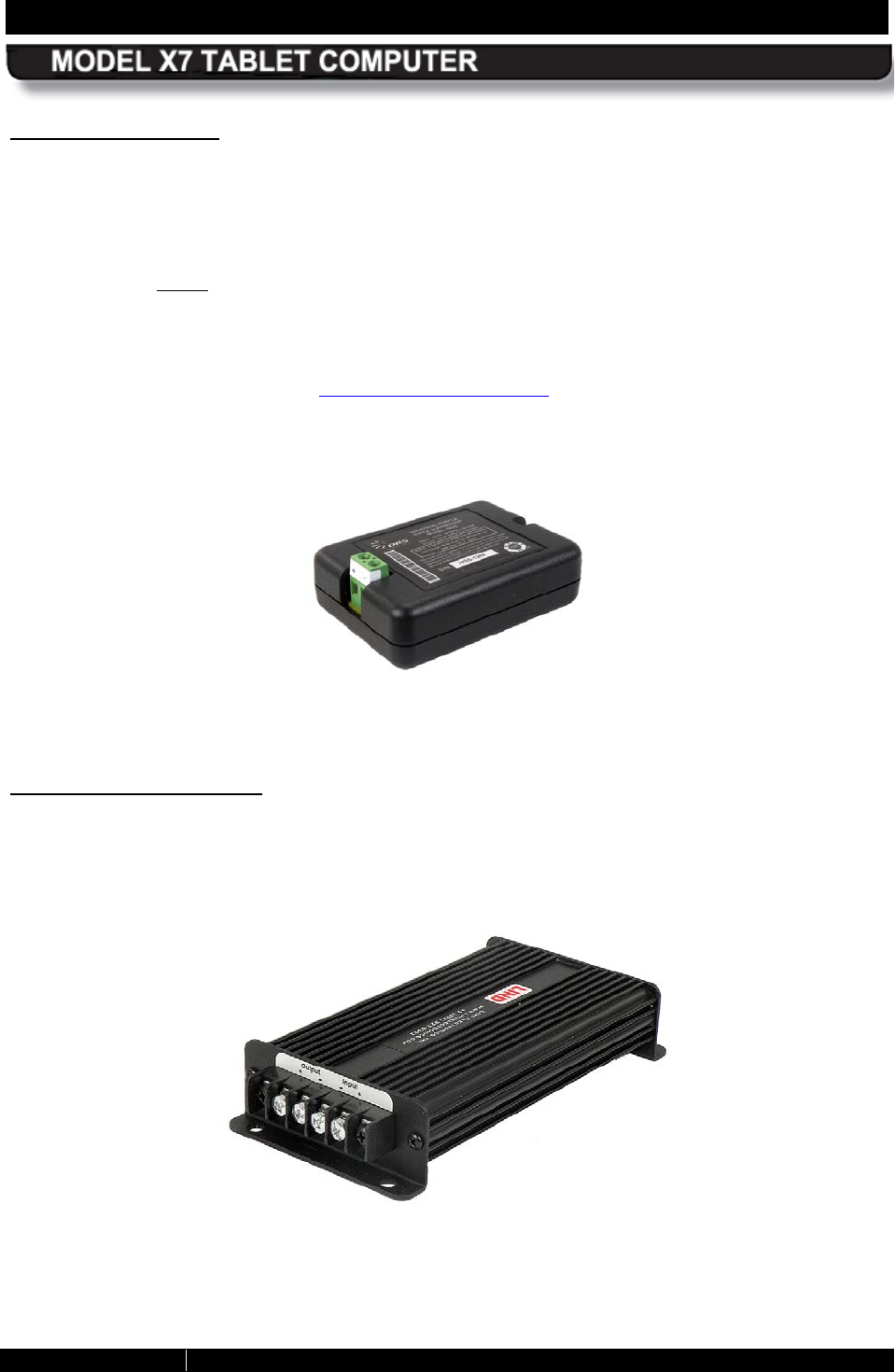
SECTION 2 LEARNING ABOUT YOUR ARMOR X7 PAGE 50
9711-26400-0001
EXPORT CONTROLLED – SEE PAGE 3
Rev A
S urge S uppressor
Surge protection is required for all vehicle installations of the ARMOR X7. This surge protection
is necessary to prevent damage to sensitive electrical circuits in the X7 tablet.
If the vehicle system voltage remains within the limits of 11-14 VDC, a regulated power supply is
not required and can be replaced with an industrial-grade surge suppressor (NOTE: If the
vehicle voltage is not controlled within these limits, a regulating power supply will be required
(see Vehicle Power Supply in this section).
DRS offers its Industrial Vehicle Surge Suppressor (IVSS) (P/N 9800F50856-0000) shown in
Figure 21. We also offer an installation kit to connect your surge suppressor to your vehicle’s
battery supply. Please contact DRS Technical Support for information and specifications
concerning this device and the required kits and parts needed for your particular vehicle
installation.
Figure 21. Industrial Vehicle Surge Suppressor
Vehicle Power S upply
The X7 vehicle power supply (P/N 5700-46340-0000) is a rugged Lind® power supply that
accepts 9-42 VDC input from the vehicle battery supply and provides a regulated 15.6 VDC
output at 6 amps maximum to the X7 system. This power supply is only required if the vehicle
power system voltage drops below 11 VDC or exceeds 14 VDC.
Figure 22. X7 Vehicle Power Supply
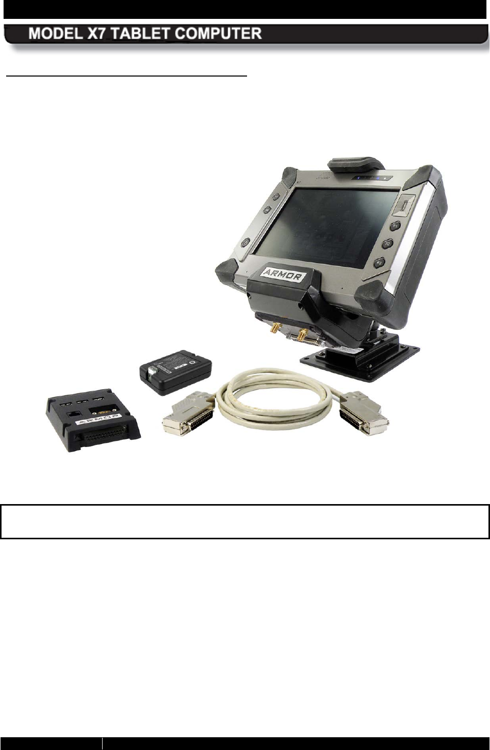
SECTION 2 LEARNING ABOUT YOUR ARMOR X7 PAGE 51
9711-26400-0001
EXPORT CONTROLLED – SEE PAGE 3
Rev A
Complete X7 Vehicle Dock Ins tallation
A complete vehicle dock installation includes a docking station, breakout box, 50-pin cable,
surge suppressor or power supply and mount of your choice. A sample system is shown in
Figure 23 (external antennas and cables not shown).
Figure 23. Sample X7 Vehicle Dock Installation Package
Contact DRS Technical Support toll free at 1-888-872-1100 for information on these and
any other accessories or add-ons.

SECTION 2 LEARNING ABOUT YOUR ARMOR X7 PAGE 52
9711-26400-0001
EXPORT CONTROLLED – SEE PAGE 3
Rev A
X7 S pecifications
NOTE: These specifications are subject to change. Please contact DRS Tactical Systems toll free at 1-888-872-1100
for updates of a particular specification.
Operating System Microsoft Windows7 Professional® or Windows 7 Ultimate® 32 bit
Processor Intel® Embedded Luna Pier system architecture with Pineview-M 1.66 GHz Single
Core Processor
512 KB L2 Cache
4-Channel Direct Memory Interface (DMI)
ICH8M I/O controller hub
Intel DX9 Graphics, 200MHz
1GB or 2GB, DDR2 667MHz SDRAM
Storage 40 GB or 80 GB embedded mSATA
Support for micro SD or SDHC memory card
Display & Graphics 7.0” WSVGA 1024 x 600 Transmissive sunlight-readable LCD
Bonded and anti-glare, anti-reflective screen treatments
LED backlighting with Automatic Light Sensor
Integrated stylus holder
Autosense dual mode digitizer, 2540 dots/inch (0.001mm resolution) and resistive
touch glass-film-glass, 2048 dots resolution (X&Y), 0.25 mm resolution and integrated
polarizer for improved viewablity
Intel DX9 Graphics controller, 200MHz
Audio Integrated enhanced acoustic speaker
2 element digital array microphone with dynamic noise cancelling CODEC
Keyboard On-screen keyboard included with Windows® 7 operating system
Accepts any USB keyboard using mini-USB adapter (not included)
Fingerprint Sensor
USB 2.0 full speed, fully encrypted, suspend and remote wakeup, selective C3
suspend support
Webcam 2.0 megapixel camera with autofocus lens
Pointer Control Touch screen pointer controlled by fingertip or inert stylus
Pen screen pointer controlled by inductive (active) pen
Optional external mouse using mini-USB adapter (not included)
Interface Connections Fixed I/O:
• DC Power input jack
• One Mini USB 2.0 port
Docking I/O:
• 10V – 30V DC power input

SECTION 2 LEARNING ABOUT YOUR ARMOR X7 PAGE 53
9711-26400-0001
EXPORT CONTROLLED – SEE PAGE 3
Rev A
• 3x USB 2.0
• 2x 5V Ground/Open Input Devices (GPIO)
• Dock detect/dock enabled discrete
• GPS antenna, coaxial
• WWAN antenna, coaxial
Mechanical features support one-handed docking
Wireless Standard:
• 802.11 A/G/N 2x2 Wireless LAN connectivity (WLAN)
• Bluetooth® v2.1 + EDR (Class 2) Bluetooth
Optional:
• Integrated GPS
• Integrated WWAN Module and Antenna
o North America: CDMA2000/1xEVDO Rev A: 850MHz/1900MHz bands
o North America: GSM/GPRS/EDGE/UMTS/HSPA
850HMz/900MHz/1800MHz/1900MHz bands
o Europe: GSM/GPRS/EDGE/UMTS/HSDPA(2100)
800MHz/900MHz/1800MHz/1900/2100 MHz bands
Flexspace Expansion Replacement of right side battery with special adapter:
• 2x USB 2.0 ports
• 2x bi-directional (GND/Open) discretes to EC processor
• +5V, 1A & +3.3V, 1A power for active modules
User accessible compartment under cooling register:
• 1x mini-PCIe port
• 4x bi-directional (GND/Open) discretes to EC processor
• 2x USB 2.0 ports
• 1x RS-232 port
• RGB video
• Microphone and stereo headphone access
• +5V, 1A & +3.3V, 1A power for active modules
Power Power Input: 10 VDC to 30 VDC (19 VDC nominal)
Battery support
• Twin hot-swappable 7.5V lithium polymer batteries (standard or high-
capacity)
• Standard capacity = 2950mAh; High capacity = 5900mAh
• Battery operation: 8 hours with two high-capacity batteries
4 hours with two standard batteries
• Battery charging time: 7 hours with two high-capacity batteries
3 hours with two standard batteries
AC Adapter: AC 100V-
240V 50/60Hz, Auto sensing/switching worldwide power
supply
Security Features Password security
Support for encrypted drives

SECTION 2 LEARNING ABOUT YOUR ARMOR X7 PAGE 54
9711-26400-0001
EXPORT CONTROLLED – SEE PAGE 3
Rev A
TPM security chip v.1.2
Fingerprint sensor
ISO 7816 Smart Card (FIPS 201) compliant
Durability Features MIL-STD-810G certified (6' drop)
IP67 certified including battery pack
Injection molded plastic housing with internal magnesium frame and rubber over mold
in hand grip areas
Environmental Operating Temperatures: -20 to +60°C
Storage Temperatures: -40 to +70°C (without batteries)
Temperature Shock: 20°C/min (operating)
Relative Humidity: +5°C to 60°C @ 95%
Altitude: 20,000 feet max, operating or non-operating
Vibration: Operating - Composite Wheeled Vehicle Exposure; Storage - Composite
Two-Wheeled Trailer Exposure
Shock: Operating - 30g, 11ms, half-sine operational shock; Storage - 50 g’s, 11ms,
half-sine. Drop test certified to 6ft/1.8m per MIL-STD-810G, Method 516.6
Ingress Protection Rating (IP) 65
Fluid Compatibility: Cat II Chemical Solvents, Cat III Cleaners and Cat IV Industrial
Chemicals
UV Exposure: 1120 W/m2 in
ESD: contact discharge ±8 kV, air discharge 22 kV
CSA C22.2 No. 213-M1987; EN60079-0, EN60079-15:2005 (ATEX)
Regulatory Certifications
UL/TUV
CSA
FCC Part 15
CE Mark
E-Mark
Energy Star
EPEAT (Silver Level)
HAZLOC/ATEX
Weight and Dimensions 3.2 lbs with two 4-cell batteries; 2.8 lbs with two standard batteries
8.9” x 5.9” x 1.4” (center) 2.1” (Hand Grips) / 225 x 150 x 35 mm (center) 54 mm
(Hand Grips)
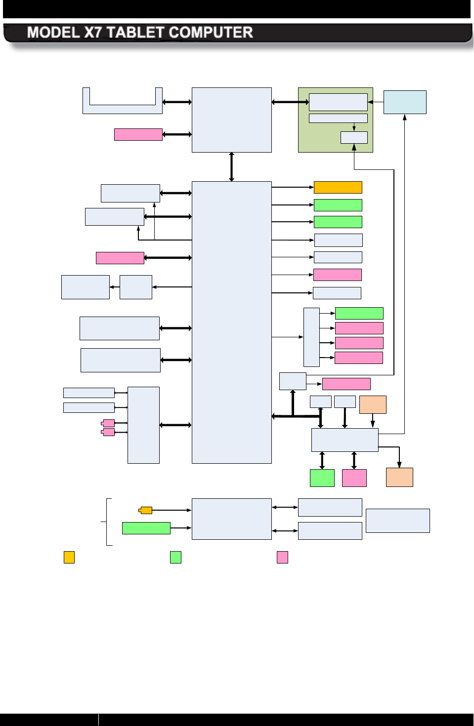
SECTION 2 LEARNING ABOUT YOUR ARMOR X7 PAGE 55
9711-26400-0001
EXPORT CONTROLLED – SEE PAGE 3
Rev A
Pineview-M
DDR2
1GB/2GB
ICH8-M
AZALIA
CODEC
HDA
Winbond
WPCE773L
LPC
TPM
LCD Display
Signals go to docking connector
Signals go to tablet connector
ROM
LVDS
NFLASH 32/64/128GB SSD
on Mini-PCIe Module
AES1660 FPR
USB Connector
Audio Out (Lt/Rt)
2MP Camera
Internal Speaker
Signals go to expansion connector
Digital Microphone x2
PCIe X1
8/16/32GB MicroSD/
SDHC
DOCK Conn
GPIO
DOCK
Conn
Microphone Input
Touch Panel
Controller
Optically Bonded LCD
Assy
PCIe X1
Bluetooth
USB Hub
Battery Exp
USB 0
USB 1
USB 2
USB 7
USB 9
Mini-PCIe WLAN
Mini-PCIe GPS
SATA 0
GPIO
EXP
Conn
Button
Board
Backlight Driver
LED
Board
GPIO
Power Supply/
Charger
Battery #1 – 2S2P
7.4v, 40WHr
Battery #1 – 2S2P
7.4v, 40WHr
Input Voltage
10V-30VDC, 2A
(max)
(19V Nominal) DOCK Conn
DC Jack
1.7mm/3.5mm
X4 DMI
DOCK Conn
USB 3
Battery Exp
USB 4
DOCK Conn
ITE
UT311-Q3
USB 8
Flexspace Exp
USB 5
USB 6
PWM
Flexspace Exp PCIe X1
Half-Size
Half-Size
SIO
Flexspace Exp
(WWAN)
Flexspace Exp
Flexspace Exp VGA
Optional Battery #1 – 2S1P
7.4v, 20WHr
Option for SATA II 1.8"
32/64/128GB
SATA 1
Figure 24. X7 Internal Block Diagram

SECTION 2 LEARNING ABOUT YOUR ARMOR X7 PAGE 56
9711-26400-0001
EXPORT CONTROLLED – SEE PAGE 3
Rev A
This Page Intentionally Left Blank
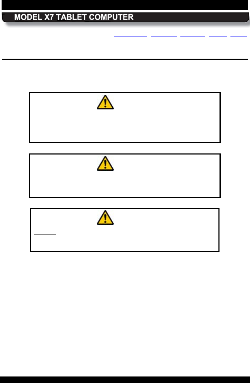
SECTION 3 GETTING STARTED PAGE 57
9711-26400-0001
EXPORT CONTROLLED – SEE PAGE 3
Rev A
Table of Contents List of Figures List of Tables Acronyms Glossary
3. GETTING STARTED
The information in this section will help you get started using your ARMOR X7 computer. Please
read all warnings, cautions and notes prior to each procedure or step.
CAUTION!
Use this product only in vehicles with a regulated voltage supply of
+10 to +30 VDC (nominal 19VDC). Voltages outside this range could
cause unstable operation or result in permanent damage to the
computer.
CAUTION!
Use only the external AC Adapter provided with your ARMOR X7 or
an equivalent model approved by DRS.
Attempting to use a
different model power supply could result in equipment damage.
CAUTION!
DO NOT connect the AC adapter power supply to the tablet when
external power is provided through a docking station. Permanent
damage to the batteries and/or computer may result.
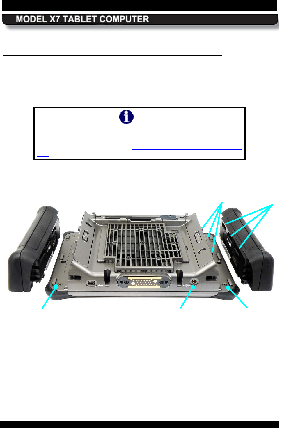
SECTION 3 GETTING STARTED PAGE 58
9711-26400-0001
EXPORT CONTROLLED – SEE PAGE 3
Rev A
Installing and Charging the B atteries
The first step to getting your X7 operating is to install and charge the batteries. The batteries are
inserted into slots or “bays” on each side of the computer as shown in Figure 25. The batteries
are identical and can be installed in either bay. Follow the procedure in Table 2 to install the
batteries.
NOTE
If you do not plan to use your computer right away, we recommend
you fully charge your batteries and then remove and store them in
a safe place until needed (see How to Store Batteries When Not in
Use).
Figure 25. X7 Batteries Positioned for Installation
BATTERY
BAY #1
BATTERY
BAY #2
DC POWER
INPUT JACK
BATTERY
LATCH
LOCKING
SLOTS
SECTION 3 GETTING STARTED PAGE 59
9711-26400-0001
EXPORT CONTROLLED – SEE PAGE 3
Rev A
Table 2. Installing the X7 Batteries
STEP ACTION
1.
Place the flat surface of the first battery on the left side compartment tray with the
locking slots facing toward the computer.
2.
Push and hold the battery latch and slide the battery toward the computer until
the locking bar engages and the battery is flush against the compartment wall.
Rock the battery slightly if necessary to engage the locking bar.
3.
Release the battery latch to lock the battery in place.
4. Perform steps 1-3 to install the second battery.
5. Connect the AC adapter to the DC power input jack on the bottom of the X7 and
plug the adapter power cord into an AC outlet.
6. Allow the batteries to charge until the Charge/Fault indicator turns off. This could
take anywhere from 2 to 5 hours depending on the type of battery and the current
level of charge of the batteries.
You can work with your X7 while the batteries
charge.
Monitoring Ins talled B attery Charge Levels
Refer to Monitoring Battery Status for information on how to check your battery status when
installed in the computer.
Checking the Charge Level of R emoved B atteries
A multi-LED battery charge indicator, or “fuel gauge”, is built into each battery, as illustrated in
Figure 26. Each LED array consists of 5 LEDs and each LED represents 20% of the total
charge of the battery as follows:
LED #5 - 81-100% (far right LED)
LED #4 - 61-80%
LED #3 - 41-60%
LED #2 - 21-40%
LED #1 - 03-20% (far left LED)
The fuel gauge indicators are not visible when the battery is installed. Press the Fuel Gauge
button to activate the fuel gauge LEDs and check the current charge level.
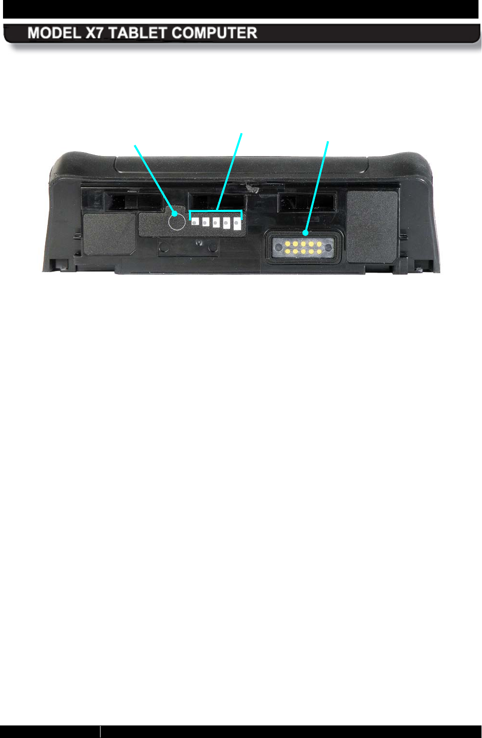
SECTION 3 GETTING STARTED PAGE 60
9711-26400-0001
EXPORT CONTROLLED – SEE PAGE 3
Rev A
Figure 26. X7 Battery
FUEL GAUGE
BUTTON FUEL GAUGE
1 2 3 4 5
BATTERY
CONNECTOR
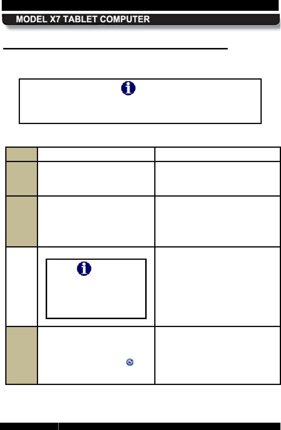
SECTION 3 GETTING STARTED PAGE 61
9711-26400-0001
EXPORT CONTROLLED – SEE PAGE 3
Rev A
Turning On your X7 for the First Time
Follow the procedure in Table 3 to configure your Windows 7 operating system.
NOTE
The first user account you create will be an Administrator account. You will
need to use this account fo
r any changes that require administrator
privileges.
Table 3. Performing the Microsoft Out-of-Box-Experience (OOBE)
STEP ACTION CONDITION OR INDICATION
1. If you have a USB keyboard available,
connect it to any USB port at this time. If you do not have an external keyboard
connected, you will need to activate the
on-
screen keyboard later in the OOBE
setup procedure.
2.
On the left control panel, press and
hold the Power button for 1-2 seconds
and then release.
When the computer boots up, the
Microsoft Out of Box Experience (OOBE)
screen will open.
NOTE: If a Sysprep window opens, click
on the down arrow and select Microsoft
Out-of-Box-Experience.
NOTE
Touch and pen screen
calibration will degrade
slightly during OOBE but will
return to normal after the
OOBE process is complete.
3.
Follow the OOBE instructions. If you
need to use the on-
screen keyboard,
wait until the OOBE process reaches
the User Account setup screen, then
click on the Accessibility icon in the
lower left corner and select Start On-
Screen Keyboard.
Once the keyboa
rd is started, you can
use it like a regular keyboard to select
options and enter data. If you have any
questions about using the virtual
keyboard, click on the Options key.
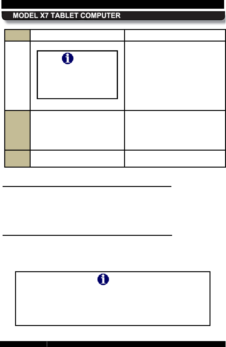
SECTION 3 GETTING STARTED PAGE 62
9711-26400-0001
EXPORT CONTROLLED – SEE PAGE 3
Rev A
STEP ACTION CONDITION OR INDICATION
NOTE
If you used the OOBE on-
screen keyboard, you must
manually turn it off o
r it will
appear each time you restart
the computer.
4.
Once you finish the OOBE, if you do
not want the on-
screen keyboard to
appear each time you log on, click on
the keyboard Options key and Select
Control whether the On-Screen
Keyboard starts when I log on.
5.
Un-check Use the On-Screen
keyboard.
Turning the C omputer On Normally
Turn the computer on by pressing the Power button for at least 1 sec and then releasing it. The
ARMOR X7 will perform self-checking routines during the start-up process. All units are
configured at the factory to automatically boot to the Microsoft Windows desktop unless a
custom configuration has been requested.
Turning the Computer Off Normally
To turn the computer off normally, select Start à Shut Down from the Windows desktop. The
computer will perform a normal shutdown. NOTE: There is a 5-10 second delay before you can
restart the computer after a complete shutdown.
NOTE
Unless you have changed the default action of the Power button, pressing
the Power button
when the computer is running will not cause it to shut
down but will put the computer into Sleep mode and the screen will go dark.
This could be mistaken for a power off condition wh
ile the computer is
actually still running and consuming battery power. When the computer is in
sleep mode, the blue Power LED on the indicator panel will flash slowly.
SECTION 3 GETTING STARTED PAGE 63
9711-26400-0001
EXPORT CONTROLLED – SEE PAGE 3
Rev A
You can re-program the power button to shut down the computer when pressed while the
computer is running. Refer to Changing the Power Button Default Action for instructions.
Emergency S hutdown
If an emergency condition occurs where the computer needs to be shut down immediately,
press and hold the Power button for more than five seconds. The computer will bypass the
normal Windows shutdown sequence and turn off.
This procedure should only be used in emergencies because improperly shutting down
Windows may result in the loss of data and possibly corrupt your operating system.
P utting the C omputer into S leep Mode
To put the computer into sleep mode (also called “standby”), press and release the Power
button while the tablet is operating. NOTE: This is the default action of the Power button when
you first receive your X7, but this can be changed in Windows Control Panel (see Changing the
Power Button Default Action).
You can also put the computer to sleep from the Windows desktop. Click on the Start button
and click the down arrow next to the Shut down button in the lower right corner of the Start
menu, then select Sleep from the drop-down menu.
To wake up the computer, press and hold the Power button for 1-2 seconds and then release.
This will take you back to the desktop and you can resume your session where you left off.
Indications that your X7 is As leep
In Sleep mode, your session is saved to RAM memory and the screen is turned off. All LEDs will
initially be off (except the Charging/Fault LED on the indicator panel if external power is
applied). Once the session has been suspended by the computer, the Power indicator LED will
flash at a 1 sec on / 2 sec off rate to indicate you are in sleep mode.
Putting the Computer into Hibernate Mode
From the Windows 7 desktop, click on the Start button and then click on the down arrow next
to the Shut down button in the lower right corner of the Start menu, then select “Hibernate”
from the drop-down menu.
When you place the computer in hibernate mode, your current session is saved to your solid-
state drive or mSATA memory and the computer is powered down. There are no visual
indications that the computer is in hibernation; the computer is powered down and all led’s will
be off, with the exception of the Charging/Fault indicator if you have external power connected.
To wake up the computer, press and hold the Power button for 1-2 seconds and then release.
This time, the computer will wake up to the locked user account selection screen. Click on the
current icon to resume your previous session. You may have to enter a password or swipe your
fingerprint, depending on how you have your login set up.
SECTION 3 GETTING STARTED PAGE 64
9711-26400-0001
EXPORT CONTROLLED – SEE PAGE 3
Rev A
Indicator S tate S ummary
Table 4 lists all states for the various X7 indicator LEDs (refer to Indicator Panel for a
description of each indicator).
Table 4. X7 Indicator State Summary
LED IF THE
INDICATION
IS:
AND
THE
POWER
MODE
IS:
AND
EXTERNAL
POWER IS:
AND
BATTERY
IS:
THIS MEANS:
Wireless
(blue) On On N/A Installed
At least one radio is
transmitting (GPS is
receive only).
Flashing
intermittently On N/A Installed The WLAN or WWAN
radio is searching for a
network connection or
Bluetooth is
transmitting data to a
peripheral.
Off On N/A Installed
One or more installed
radios (excluding GPS)
are disabled in
ARMORutils. See
Wireless Setup Dialog.
Storage
Activity
(blue)
Flashing
intermittently Power on N/A Installed Processor is accessing
a storage device
(SSHD, mSATA
memory or micro SD
card).
Charging/F
ault
(amb/red)
Off Power on Disconnected Installed No power
faults are
detected
On steady
amber Power off Connected Installed Batteries are fully
charged
Flashing
amber at 1
sec rate
Power on
or off Connected Installed Batteries are charging
SECTION 3 GETTING STARTED PAGE 65
9711-26400-0001
EXPORT CONTROLLED – SEE PAGE 3
Rev A
LED IF THE
INDICATION
IS:
AND
THE
POWER
MODE
IS:
AND
EXTERNAL
POWER IS:
AND
BATTERY
IS:
THIS MEANS:
Flashing
amber at 1/2
sec rate
Power on
or off Connected Installed
Battery charging has
been suspended due to
extreme battery
temperature
. Charging
will resume when
temperature is between
0°C and 45°C.
On steady
red Power on
or off Connected Installed
Power system fault
(overvoltage,
undervoltage or
overcurrent condition or
battery failure).
NOTE:
The LED will
turn off when the fault
condition is removed.
Power
(blue) On On N/A Installed
Computer is powered
up.
Flashing 1
sec on, 2 sec
off
Reduced N/A Installed Computer
is in sleep
mode.
Off Off N/A Installed
Computer is powered
off or is in hibernate
mode.
Fuel Gauge
(blue)
NOTE:
Press fuel
gauge
button to
activate
LEDs
Single LED
on steady N/A N/A Removed Total charge is max for
that level (20%, 40%
etc.)
LED # 1 (far
left) flashing
at 1 second
rate
N/A N/A Removed
Battery is below 10%
charge level (depleted)
All LEDs off N/A N/A Removed Battery is fully
depleted. See What to
Do for an Overly-
Discharged Batter.
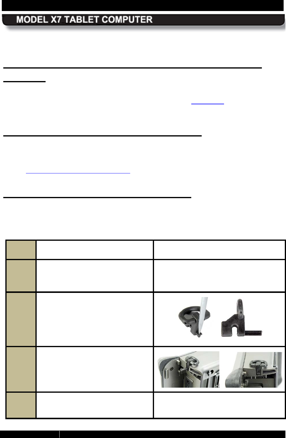
SECTION 3 GETTING STARTED PAGE 66
9711-26400-0001
EXPORT CONTROLLED – SEE PAGE 3
Rev A
Configuring and Controlling your Wireless
R adios
For instructions on configuring and controlling your wireless radios, including the optional
WWAN radio and optional GPS receiver, refer to Section 4, Networking. You will also find
instructions for connecting to a cabled LAN.
Ins talling a Micro S D/SDHC Card
A micro SD/SDHC card can provide up to 32GB of additional data storage. The socket for this
card is located inside the computer and is accessed by removing the cooling register/cover at
the back of the computer. For instructions on how to remove the rear cover and install the card,
refer to Installing a Micro SD or SDHC Card.
Installing the Optional D-R ings
Follow the procedure in Table 5 to install a D-ring to each of the four accessory mounting points.
Table 5. Installing the D-Rings
STEP ACTION COMMENTS
1. Remove both batteries
to access the
accessory mount points. NOTE: The accessory mount points are
located on the top and bottom panels of
the X7 (see Figure 7).
2. Using a pointed object
such as a
dentist probe or large pin, slide out
the locking bar on each D-Ring until it
clears the center opening
, as shown
in the image to the right.
3. Insert a D-
Ring onto each accessory
mount point and push the locking bar
in all the way.
4. Replace both batteries.
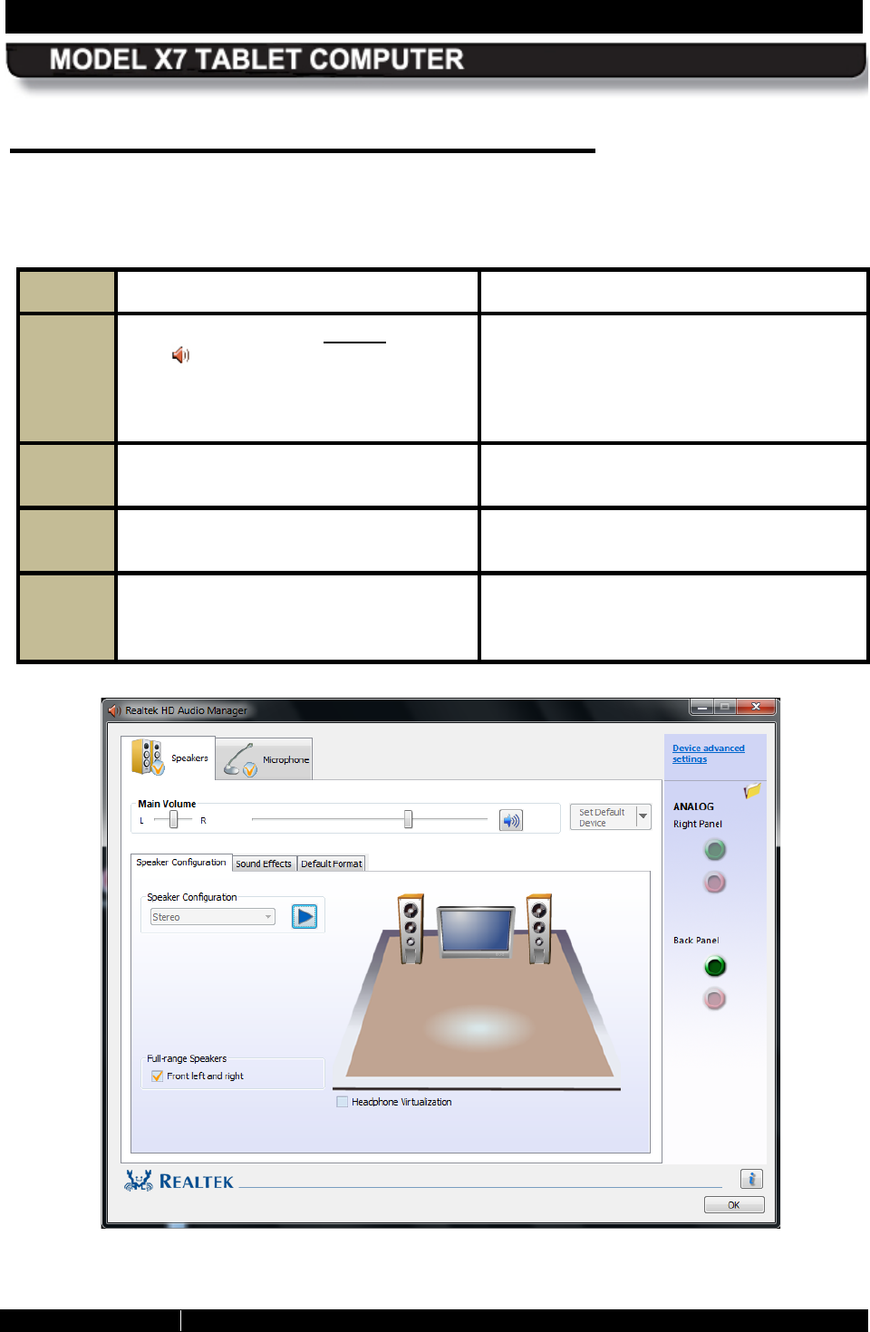
SECTION 3 GETTING STARTED PAGE 67
9711-26400-0001
EXPORT CONTROLLED – SEE PAGE 3
Rev A
Configuring your Audio S ystem
Follow the procedure in Table 6 to configure your speaker. Follow the procedure in Table 7 to
configure your microphones.
Table 6. Configuring the Speaker
STEP ACTION CONDITION OR INDICATION
1. Double-click on the orange speaker
icon in the systray.
The Realtek® HD Audio Manager window
opens with the Speakers main tab (top of
page) open and the Speaker
Configuration sub-
tab displayed, as
shown in Figure 27
2.
Adjust your speaker/headset volumes
as desired.
3. Select the Sound Effects sub-
tab to
select special effects.
4.
Select the Default Format sub-tab to
choose your default sound format.
.
Figure 27. Realtek HD Audio Manager - Speakers Main Tab
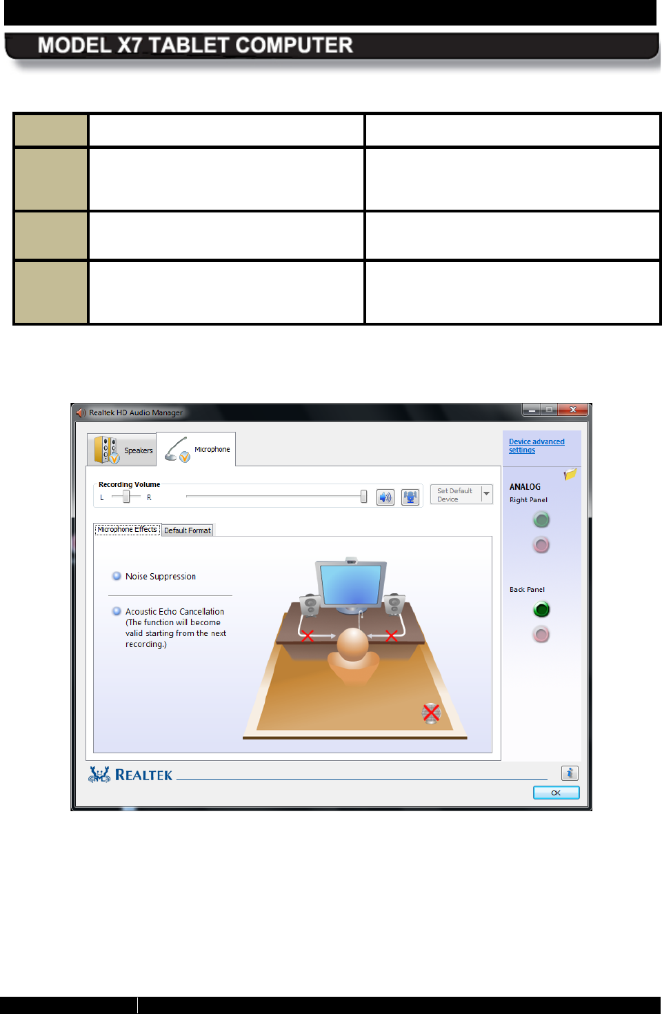
SECTION 3 GETTING STARTED PAGE 68
9711-26400-0001
EXPORT CONTROLLED – SEE PAGE 3
Rev A
Table 7. Configuring your Microphones
STEP ACTION CONDITION OR INDICATION
1. Click on the Microphone main tab at
the top of the page. The Microphone main tab opens with the
Microphone Effects sub-
tab displayed,
as shown in Figure 28.
2.
Set up and adjust your microphones.
3. Click on the Default Format sub-tab
to select a default sound format for
your microphones.
Figure 28. Microphone Main Tab
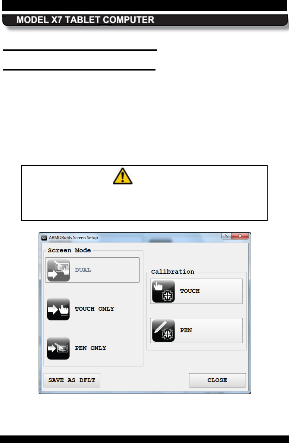
SECTION 3 GETTING STARTED PAGE 69
9711-26400-0001
EXPORT CONTROLLED – SEE PAGE 3
Rev A
Operating the X7 Display
S electing the Dis play Mode
Your X7 has the capability to operate with both a touch screen and a pen screen enabled (dual
mode) or you can select touch screen only or pen screen only. The default display mode is
“Dual Mode”.
To select touch or pen screen only operation, click on the ARMORutils icon in the systray
menu, then select the Screen Setup option from the Main screen. The Screen Setup dialog
opens, as shown in Figure 29.
Click on Touch Only to deactivate the pen screen, or click on Pen Only to deactivate the touch
screen. The screen option that is enabled will appear grayed out in the Screen Setup dialog,
indicating that it is selected and the other modes are available. Click on Dual Mode to re-enable
both screens.
CAUTION!
If you change to Pen Only mode using the touch screen and you do not
have an active pen, you will not be able to access the screen or switch back
to Dual or Touch Only modes unless you attach an external USB mouse or
obtain an active pen. Restarting the computer will not change anything.
Figure 29. ARMORutils Screen Setup
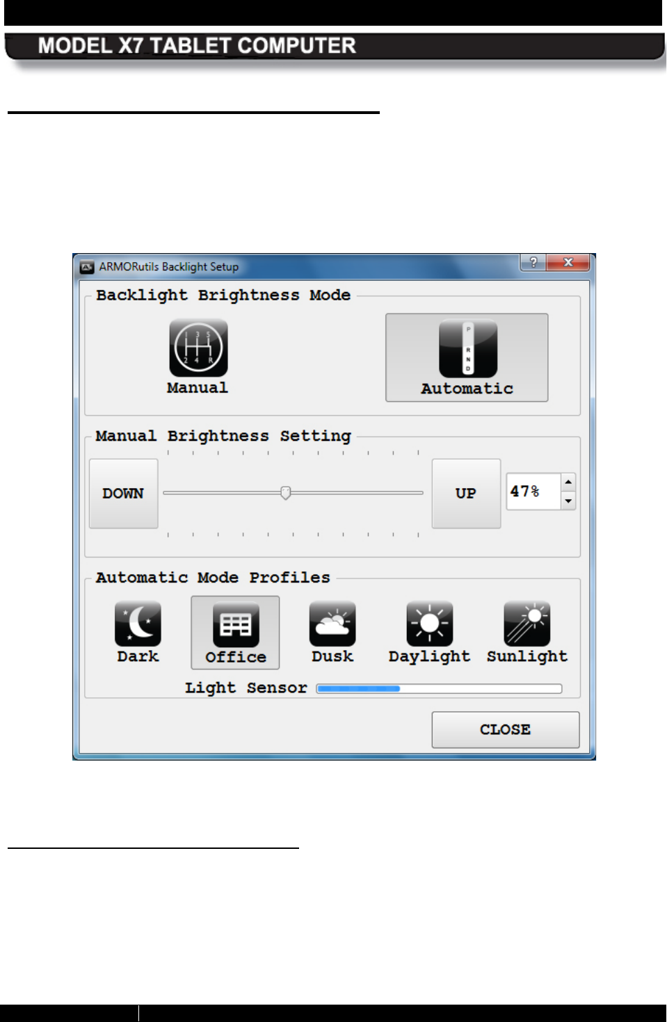
SECTION 3 GETTING STARTED PAGE 70
9711-26400-0001
EXPORT CONTROLLED – SEE PAGE 3
Rev A
Adjusting Screen B rightness
The brightness of the LCD display is controlled by adjusting the backlight intensity either
automatically or manually. When you first receive your ARMOR X7, the brightness mode is set
to Automatic. To switch to Manual brightness control, or switch back to Automatic mode, open
ARMORutils and click on the Backlight Setup option in the ARMORutils Main dialog window.
This will open the Backlight Setup dialog window shown in Figure 30.
Figure 30. ARMORutils Backlight Setup Dialog Window
Automatic Brightness Adjus tment
Click on the Automatic button to change to the automatic brightness mode. The backlight level
will now be controlled by the ambient light sensor (ALS) located on the indicator panel. If the
surrounding light decreases, the brightness will decrease proportionally; if the surrounding light
increases, the brightness will increase proportionally.
SECTION 3 GETTING STARTED PAGE 71
9711-26400-0001
EXPORT CONTROLLED – SEE PAGE 3
Rev A
NOTE
You must keep the ALS
uncovered to allow proper automatic
brightness adjustment.
S electing an Automatic Mode Profile
You can tailor the automatic brightness adjustment by selecting one of the 5 pre-configured
brightness profiles. DRS has researched typical lighting environments and has created these
adjustment profiles that respond more precisely to changing light levels within a particular
environment.
For example, if the automatic brightness doesn’t keep the display bright enough for you under
surrounding lighting conditions, you can select the Dusk, Daylight or Sunlight profile to increase
the brightness range proportionally. Similarly, if the normal brightness control results in light
levels that are consistently too bright, you can select the Office or Dark profile to reduce the
brightness range.
Manual Brightness Adjustment
Click on the Manual button to change to manual brightness mode. You can manually adjust
screen brightness in two ways: by using pre-programmed buttons (PBs) P1, P2 and P3 or by
using options and buttons in the Backlight Setup dialog.
Using P1, P2 and P3 to Adjus t B rightnes s
When you first receive your X7, the P1 button is programmed to increase screen brightness
in 10% steps, P2 is programmed to decrease brightness in 10% steps and P3 is
programmed to toggle the screen full off and on.
NOTE: ARMORutils must be running to use the PB functionality (see Starting ARMORutils).
Press and release P1 repeatedly to increase the brightness to its maximum level (100%);
press P2 repeatedly to decrease the brightness to its minimum level (10%). Press P3 to turn
the screen completely off; press it again to turn the screen back on to it’s previously set
level.
NOTE: P1, P2 P3 are initially programmed to adjust screen brightness; however, you can
change each button’s programming as described in Buttons Setup Dialog.
Us ing the B acklight S etup Dialog to Adjus t B rightnes s
Drag the slider or press the UP or DOWN buttons repeatedly with the pen or a fingertip to
move the slider and adjust the brightness level. The % brightness is displayed in a field on
the right. You can also use the up and down arrows next to this field to adjust the slider.
SECTION 3 GETTING STARTED PAGE 72
9711-26400-0001
EXPORT CONTROLLED – SEE PAGE 3
Rev A
Working with the Pen S creen
When the pen screen is active, you can steer the pointer and perform many functions by simply
hovering close to the screen without actually touching it. Other functions are initiated by
pressing the tip to the screen surface to activate the tip switch.
Your X7 Active Pen
The pen that comes with your X7 (Figure 9) is stored in a slot on the back panel (see Figure 4)
and has circuitry that interacts with the pen screen digitizer assembly. The digitizer detects the
pen tip close to the screen and activates certain functions like steering the pointer or performing
a right click action if the side button is pressed. Pressing the tip to the screen activates a tip
switch that opens a right-click menu.
Us ing the Ac tive Pen
Table 8 lists mouse-type objectives you can perform using the X7 pen with the pen screen.
NOTE
This description assumes the side button is set for the Right-Click
function (default). This function can be
changed as described in
the Pen Tablet Properties utility in Control Panel.
Table 8. Pen Screen Actions.
MOUSE OBJECTIVE PEN ACTION
Select option or tab or open submenus.
Fill selection boxes.
Activate buttons.
Deselect highlighted objects (touch
next to
the object).
Tap once
Selects multiple objects. Touch pen tip to display and drag box around
objects
Highlight object or option. Hover over object or option
Move object on the desktop. Touch an object and move it with the pen.
Start application or open folder. Tap twice
Highlight option, open menus (right click). Hold tip to screen
-or-
Hover near screen and press side button (see
Pen Tablet Properties Utility
for other side
switch options).

SECTION 3 GETTING STARTED PAGE 73
9711-26400-0001
EXPORT CONTROLLED – SEE PAGE 3
Rev A
Pen S creen Adjustments
You can change attributes related to use of the pen with the pen screen by selecting Start à
Control Panel à Hardware and Sound à and clicking on one or more of the following utilities:
• Pen Tablet Properties utility
• Pen and Touch utility
• Tablet PC Settings utility
Refer to Windows Display Utilities for information about these utilities.
Pen Screen Calibration
After a period of normal usage, the screen may need to be calibrated with the pen to ensure the
pen tip is aligned with the pointer over the entire screen area. Refer to Calibrating the Display.
SECTION 3 GETTING STARTED PAGE 74
9711-26400-0001
EXPORT CONTROLLED – SEE PAGE 3
Rev A
Working with the Touch S creen
When the touch screen is active, the pressure of a fingertip or passive stylus (not supplied)
against the screen is used to duplicate the actions of a two-button mouse.
NOTE
Tapping with a stylus tip requires only light to moderate
pressure. It is possible to damage the stylus
tip and/or the
display by pounding the tip against the surface with too much
force.
Table 9 lists mouse-type objectives you can perform using a fingertip or passive stylus with the
touch screen.
Table 9. Stylus Actions.
MOUSE OBJECTIVE STYLUS ACTION
Select tabs or open sub-menus.
Highlight a label or option.
Fill selection boxes.
Activate buttons.
Deselect highlighted objects or release multiple
objects
Tap once
Tap outside the object(s)
Start an application or open a folder. Tap twice
Move an object on the desktop.
Press over an object, hold contact with
display, drag pen and release pressure.
Open menu options. Press over icon or option and hold contact
with display without moving pen.
Select multiple objects. Press and hold contact with display, drag
box around objects.
Touch S creen Adjus tments
You can change attributes related to use of a fingertip or passive stylus. Select Start à Control
Panel à Hardware and Sound à and click on either the Touch Settings utility, Pen and
Touch utility or the Tablet PC Settings utility. Each utility controls different attributes of the
touch screen. Refer to Windows Display Utilities for an explanation of these attributes.

SECTION 3 GETTING STARTED PAGE 75
9711-26400-0001
EXPORT CONTROLLED – SEE PAGE 3
Rev A
Touch S creen Calibration
NOTE
If your X7 is in Dual Mode display, you cannot use the active pen
that came with your X7 to calibrate the touch screen since the
digitizer
will detect the active pen tip and not allow you to
proceed.
You will need to calibrate the touch screen using a fingertip or a passive stylus (not included
with the X7) to ensure the actual touch point matches the position of the pointer. For calibration
instructions, refer to Calibrating the Display.
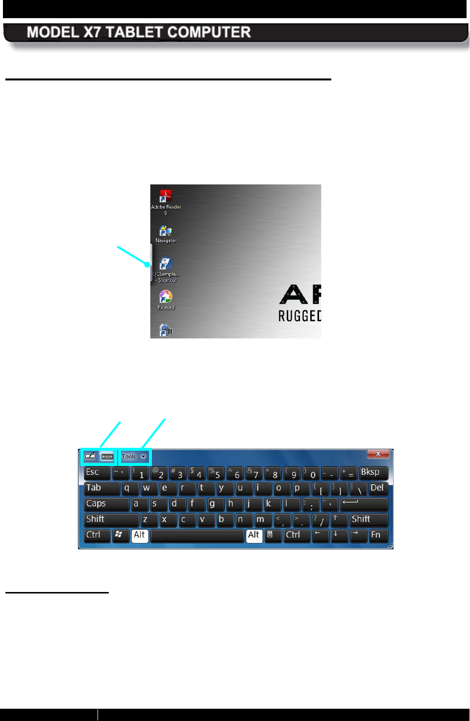
SECTION 3 GETTING STARTED PAGE 76
9711-26400-0001
EXPORT CONTROLLED – SEE PAGE 3
Rev A
Entering Data Using the Input Panel
The input panel is a virtual keyboard and handwriting entry tool that is located on your desktop.
It is hidden just off the top left or right side of the display. The edge appears in the upper left
corner when you tap anywhere on the screen with a fingertip, stylus or the active pen, as shown
in Figure 31.
When the edge is visible, tap on it twice to fully open it on the desktop, as shown in Figure 32.
Figure 31. Location of the Input Panel
Figure 32. Input Panel Keyboard Opened on Desktop
Operating Modes
The input panel has two modes: handwriting and keyboard entry. These are selectable by the
two mode icons at the upper left corner. NOTE: The panel will always re-open in the last mode
used.
Click on the Tools menu for handwriting options and for information on how to set up and use
Input Panel.
MODE
ICONS
OPTIONS AND
HELP
EDGE OF HIDDEN
INPUT PANEL
SECTION 3 GETTING STARTED PAGE 77
9711-26400-0001
EXPORT CONTROLLED – SEE PAGE 3
Rev A
E diting Documents
When you tap on an open text document such as a Word document, a keyboard icon will
appear on the screen. Tap on this icon to open the input panel.
Configuring Input Panel Options
The Input Panel Options window is where you can change a wide variety of Input panel display
and operating features. There are two ways to get to this window:
1. Click on Control Panel à Hardware and Sound à Tablet PC Settings and select the
Other tab, then click on Go to Input Panel Settings.
2. With the Input Panel keyboard open on the desktop, click on the down arrow next to the
Tools button and select Options.
Click on the link Learn More About Opening and Moving Input Panel at the bottom of the
options window to access a Windows help tutorial about opening and position the Input Panel.
Opening Input Panel with a Ges ture
You can also use a side-to-side gesture to open the input panel. Select Start à Control Panel
à Hardware and Sound à Pen and Touch, then highlight Start Tablet PC Input Panel in the
Pen Actions panel and click on Settings.
When the Start Input Panel Gesture Settings window opens, check the Enable Start Input
Panel gesture option. Follow the instructions to test and adjust your gesture.
E ntering Data us ing Other Virtual Input Devices
There are a number of on-screen keyboards offered by companies other than Microsoft, such as
the My-T-Pen® Onscreen Virtual Keyboard Utility and the Comfort® On-Screen Keyboard for
Windows.
There are also other types of software and hardware input devices besides virtual keyboards
that can be used for viewing and entering data, such as hand gesture recognition software and
infrared tracking devices.
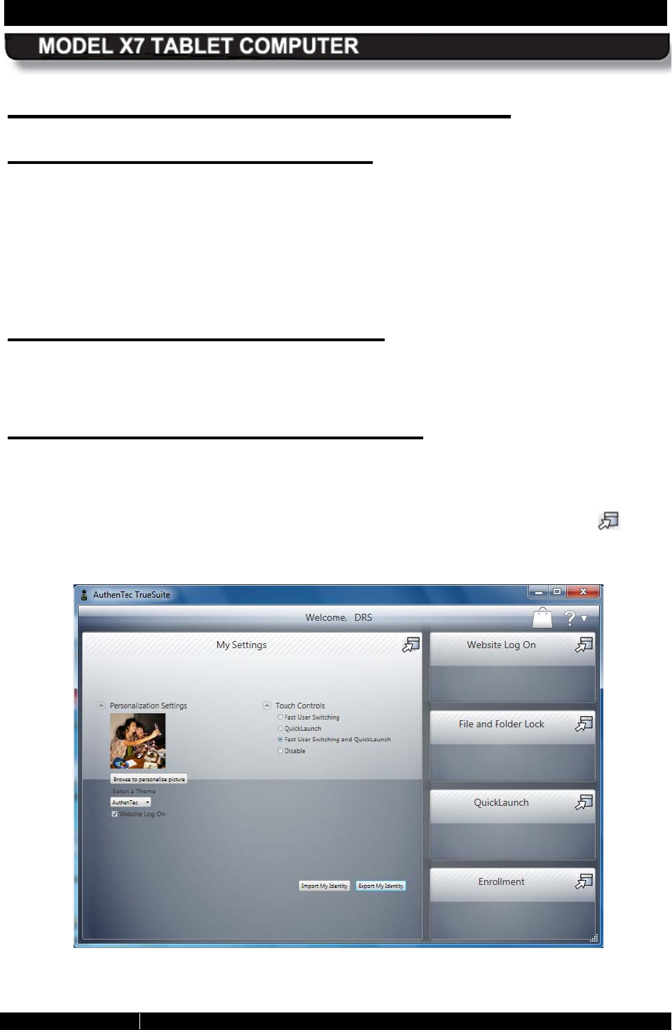
SECTION 3 GETTING STARTED PAGE 78
9711-26400-0001
EXPORT CONTROLLED – SEE PAGE 3
Rev A
Using the Fingerprint S ensor (FPS )
Activating the FPS Software
To initially set up your FPS software, double-click on the TrueSuite icon on the desktop and
click on Get Started to begin. This will take you through the steps to enroll, or register, your
fingerprint(s). The fingerprint sensor is located on the right side of the tablet in the middle of the
row of buttons.
Once you have enrolled your fingerprints, you will need to swipe in each time you restart the
computer.
Using the Fingerprint S ensor
To use the fingerprint sensor, swipe your finger or thumb from side to side at medium speed
across the sensor.
Us ing the TrueS uite Application
Open the TrueSuite application by double-clicking on the TrueSuite icon on the desktop or by
selecting Start à All Programs and clicking on the TrueSuite folder in the programs list (you
may have to scroll down to see it). Click on the TrueSuite option to open the application, as
shown in Figure 33. There are five user panels available. Click on the navigation icon in the
upper right corner to open a panel.
Figure 33. TrueSuite Application Window

SECTION 3 GETTING STARTED PAGE 79
9711-26400-0001
EXPORT CONTROLLED – SEE PAGE 3
Rev A
TrueS uite Options and S ettings
A complete description of the options and settings of the TrueSuite software is beyond the
scope of this user’s guide. Click on the “?” in the upper right corner of the window to access the
application’s help resources for detailed descriptions and instructions.
Uninstalling your Fingerprint S oftware
Should you decide to uninstall your fingerprint software, be sure to use the uninstall program
provided with the AuthenTec software rather than through Control Panel. Click on Start à All
Programs à TrueSuite à Uninstall TrueSuite.
SECTION 3 GETTING STARTED PAGE 80
9711-26400-0001
EXPORT CONTROLLED – SEE PAGE 3
Rev A
Using the Webcam
Capturing Images and Video
Image and video capture is performed using the built-in webcam and image capture software.
Your X7 is provided with a complementary version of Picasa 3™ to demonstrate the image
capture process, or you may wish to download and install your own camera application.
Follow the procedure in Table 10 to capture and save a still image or movie using the Picasa 3
software.
NOTE
Remove the blue protective film from the webcam lens before
using the camera.
Table 10. Capturing a Still Image or Video
STEP ACTION COMMENTS
1.
Double-click on the Picasa 3 icon on the
desktop. The Picasa application window will open
as shown in Figure 34.
2.
Click on the “
Capture photos or
video…” button in the options bar (see
Figure 34).
A Capture dialog window will open
displaying the current webcam image.
3.
To capture the image as a still image,
click on the camera
button below the
image.
Each capture will appear as a thumbnail
at the bottom of the window.
4.
When finished, click on the Done button
to access editing and correction options
or to save or upload your images.
5.
To capture moving video, click on the
Record button below the image.
The capture window will change to a
viewer with options to view, save and
upload your captured video.
6.
To return to the main window, click on the
Back to Library button.
7.
Refer to the Picasa Help resources for
detailed instructions.
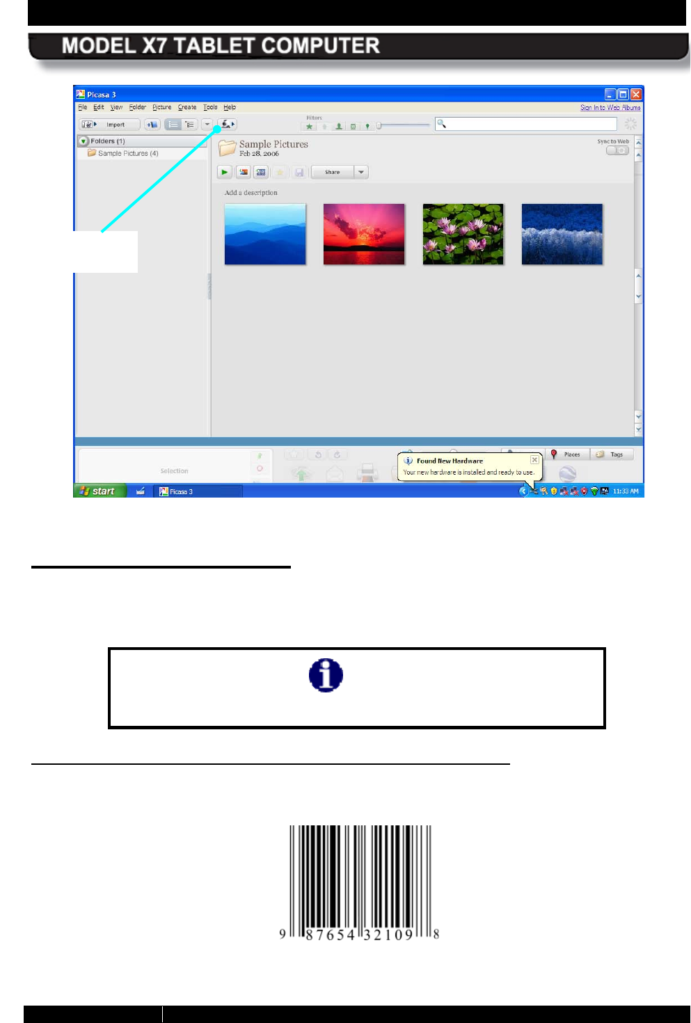
SECTION 3 GETTING STARTED PAGE 81
9711-26400-0001
EXPORT CONTROLLED – SEE PAGE 3
Rev A
Figure 34. Picasa Application Window
Scanning a B arcode
The built-in webcam and the application software of your choice will allow you to scan various
types of barcodes and incorporate them in to your documents. We have included two simple
applications to demonstrate the barcode scanning capabilities of the X7.
NOTE
Ensure that adequate light can reach the barcode to be scanned.
S canning Linear B arcodes (UPC-10, E AN-13, IS B N, etc .)
Figure 35 shows a sample of a linear barcode. Follow the procedure in Table 11 to scan a linear
barcode.
Figure 35. Sample Linear Barcode
CAPTURE
BUTTON
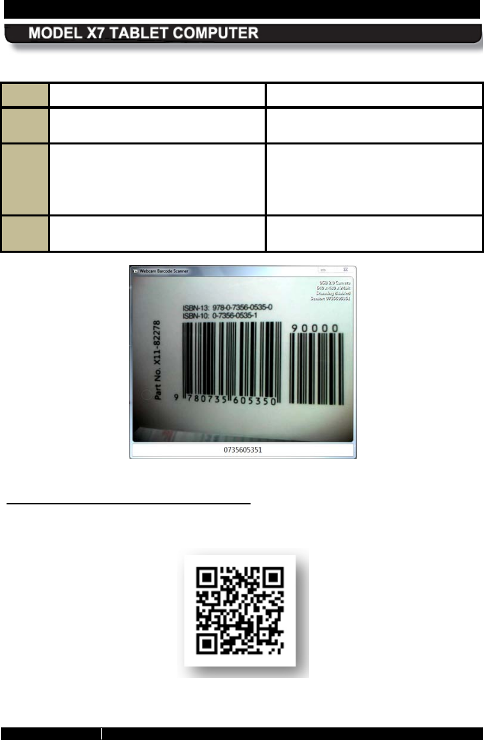
SECTION 3 GETTING STARTED PAGE 82
9711-26400-0001
EXPORT CONTROLLED – SEE PAGE 3
Rev A
Table 11. Scan UPC-10, EAN-13 and ISBN Barcodes
STEP ACTION COMMENTS
1.
Double-click on the
Webcam Barcode
Scanner icon on the desktop. The application window opens as shown
in Figure 36
2.
Hold the barcode to be scanned 2-3” from
the camera and hold it steady. A tone will announce successful barcode
capture, and the barcode number will
appear at the bottom of the window. The
captured barcode is stored in the
Windows clipboard.
3.
To use a barcode in an application, place
the pointer in a field and paste.
Figure 36. Webcam Barcode Scanner® Application Window
2D B arcodes (Datamatrix or QR format)
A sample 2D barcode is shown in Figure 37. Follow the procedure in Table 12 to scan a 2D
barcode.
Figure 37. Sample 2D Barcode
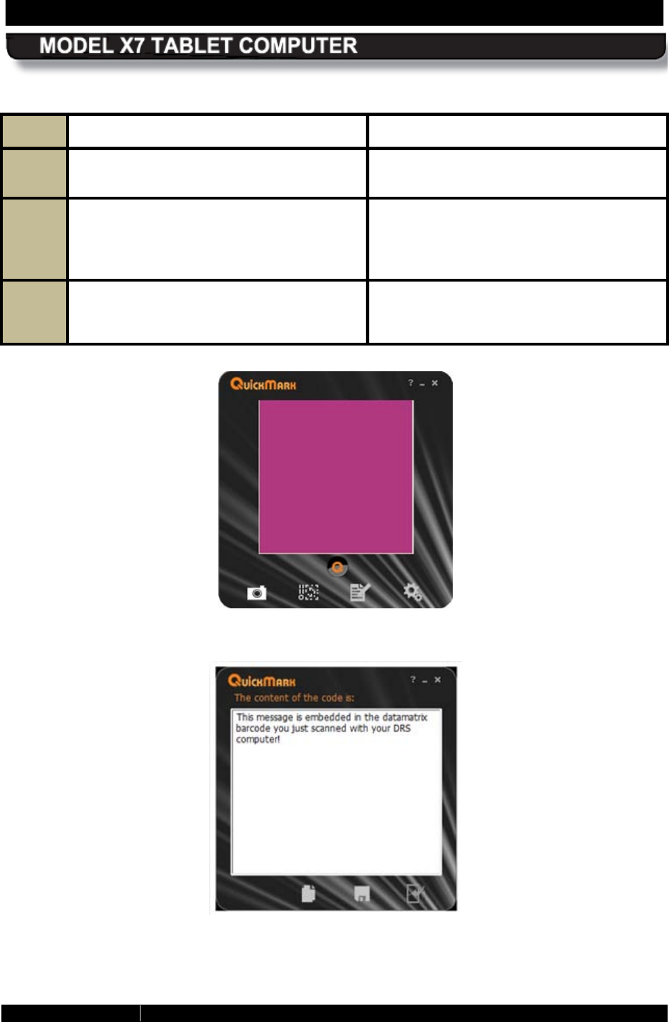
SECTION 3 GETTING STARTED PAGE 83
9711-26400-0001
EXPORT CONTROLLED – SEE PAGE 3
Rev A
Table 12. Scan a 2D Barcode
STEP ACTION COMMENTS
1.
Double-click on the QuickMark icon on
the desktop.
The QuickMark® application window
opens as shown in Figure 38
2.
Hold the barcode to be scanned 2-3” from
the camera, An audible signal will sound upon capture
and the barcode information
will be
displayed in the application window
, as
shown in Figure 39.
3.
To return to the camera mode, click on
the door icon at the lower right corner of
the window.
Figure 38. QuickMark® Barcode Scanner Application Window
Figure 39. A Captured 2D Barcode
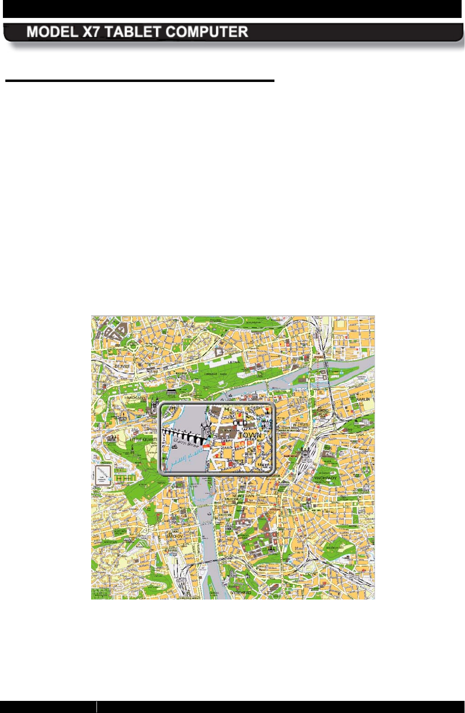
SECTION 3 GETTING STARTED PAGE 84
9711-26400-0001
EXPORT CONTROLLED – SEE PAGE 3
Rev A
Using the S creen Magnifier
Some text and images on a small screen can be difficult to see clearly. Your X7 has a handy
application that will magnify a portion of the screen and help you see more effectively. The
program is called Virtual Magnifying Glass™.
• To start the application, click on the Virtual Magnifying Glass icon on the desktop or
select Start > Programs > Virtual Magnifying Glass. An icon will also appear in the
system application tray (systray).
• Use the scroll wheel to increase or decrease magnification. The application will return to
the last magnification used when restarted.
• Left click to close the magnifier.
• To access the Virtual Magnifying Glass configuration menu, right-click on the icon in the
systray.
• A magnified example is shown in Figure 40.
Figure 40. Virtual Magnifying Glass at Work

SECTION 3 GETTING STARTED PAGE 85
9711-26400-0001
EXPORT CONTROLLED – SEE PAGE 3
Rev A
Tips for Proper Use and Care Of Your X7
There are certain precautions you should take to ensure that your ARMOR X7 computer
continues to provide you with reliable service:
• Do not subject the computer to heat by placing it on the dashboard of a vehicle with the
display facing the sun.
• Do not store the computer in temperatures below -40°C or above 70°C.
• Do not pile tools or heavy objects on top of the computer.
• Avoid severe impacts, especially to the display.
• Do not try to take the computer apart. Disassembly of the unit by unauthorized personnel
may void your warranty.
• Do not use excessive force when inserting removable cards. They are keyed to go in
only one way and inserting a card incorrectly or using excessive force could result in
damage to the card or the computer.
• Keep your screen clean and calibrated.

SECTION 3 GETTING STARTED PAGE 86
9711-26400-0001
EXPORT CONTROLLED – SEE PAGE 3
Rev A
This Page Intentionally Left Blank

SECTION 4 NETWORKING PAGE 87
9711-26400-0001
EXPORT CONTROLLED – SEE PAGE 3
Rev A
Table of Contents List of Figures List of Tables Acronyms Glossary
4. NE TWOR K ING
Your ARMOR X7 comes configured with two wireless network capabilities: Wi-Fi™ (wireless
fidelity) and Bluetooth®. The Wi-Fi network is primarily used for higher bandwidth connections
such as Internet or a company LAN. The Bluetooth network is used for connecting wireless
devices such as a wireless router, printer or scanner to your computer.
The X7 can also accommodate an optional factory-installed WWAN radio and/or GPS receiver.
These wireless devices are described in Optional Add-ons and Accessories for Your X7.
Please contact DRS Technical Support for information about installing these options.
Your X7 can be connected to a cabled LAN through the breakout box on a desk or vehicle
docking station.
Managing your Wi-Fi Connections
Your Wi-Fi (WLAN) radio is already configured and operating when your computer starts. Refer
to Table 13 for instructions on how to manage your WLAN connections.
NOTE
The Windows Network and Sharing Center window
in Control
Panel will show you all of the networks you
can select or
manage. If you have an optional Gobi WWAN card, it is best to let
the Sierra OneClick Internet
connection manager application
control your WWAN network connection. For instructions, please
refer to the Sierra OneClick Connection Manager .
Table 13. View and Manage Network Connections
STEP ACTION COMMENTS
1. Select Start
à
Control Panel
à
Network and Internet
à
Network
and Sharing Center.
The Network and Sharing Center window
opens, as shown in Figure 41.
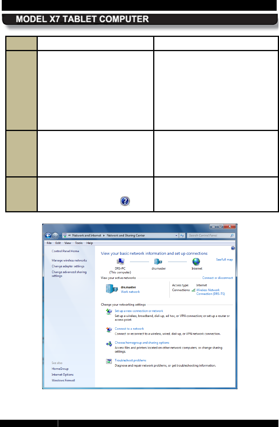
SECTION 4 NETWORKING PAGE 88
9711-26400-0001
EXPORT CONTROLLED – SEE PAGE 3
Rev A
STEP ACTION COMMENTS
2. Click on the “Connect to a network”
link to open the window shown in
Figure 42. Click outside this window to
close it.
The label “Connected” will appear beside
each network you are currently
connected to. Any other available
networks are also listed.
The green signal
bars indicate the
relative strength of the wireless signal. A
yellow shield indicates those sites that do
not have security enabled. Use caution
when connecting to these sites.
3.
To connect to a network, click on the
network name and select Connect. To
disconnect from an active network,
click on the name and select
Disconnect.
4.
For more detailed information on the
options and settings for these
windows, click on the Help icon
Figure 41. Network and Sharing Center Window
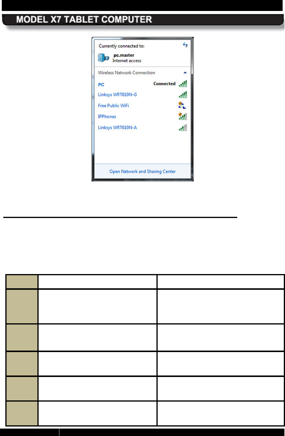
SECTION 4 NETWORKING PAGE 89
9711-26400-0001
EXPORT CONTROLLED – SEE PAGE 3
Rev A
Figure 42. Currently Connected and Available Wi-Fi Networks
Managing your B luetooth Connections
Your X7 comes equipped with Bluetooth® networking. However, to utilize this feature, you must
“associate” your computer with any Bluetooth devices you want to connect. To see what
Bluetooth devices are available and to add or remove devices, follow the procedure in Table 14.
Table 14. View and Manage Bluetooth Devices
STEP ACTION COMMENTS
1. Select Start
à
Control Panel
à
Hardware and Sound
à
Devices
and Printers.
The Devices and Printers window opens
(Figure 43) showing any peripherals are
in range or are already connected
(including cabled devices).
2. Right-
click on the icon for your
computer and select Bluetooth
settings from the menu.
The Bluetooth Settings window opens, as
shown in Figure 44.
3. Check the “
Allow Bluetooth devices
to find this computer” option.
4. Check the “
Allow Bluetooth devices
to connect to this computer” option.
5. To add a device, click on the “
Add a
device” option in the toolbar.
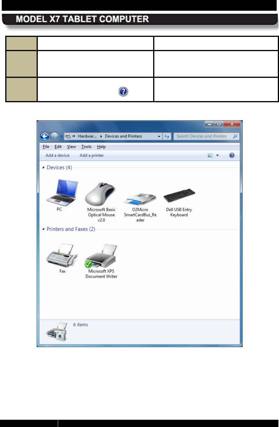
SECTION 4 NETWORKING PAGE 90
9711-26400-0001
EXPORT CONTROLLED – SEE PAGE 3
Rev A
STEP ACTION COMMENTS
6.
To remove a device, click on the
“Remove a device” option in the
toolbar.
7. For additional information about these
windows, click on the Help icon.
Figure 43. Devices and Printers Window
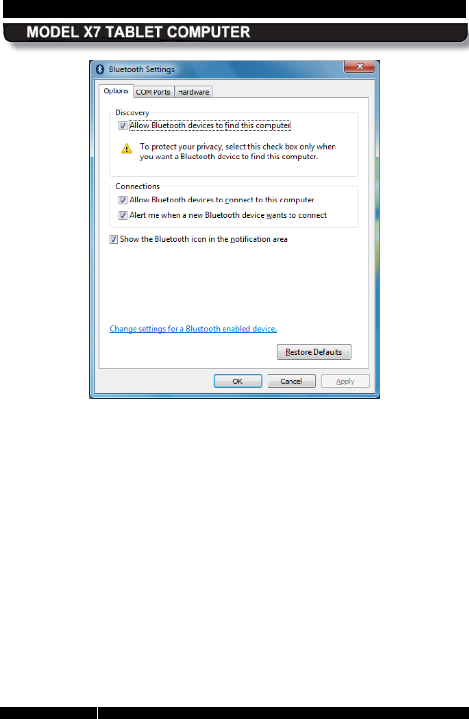
SECTION 4 NETWORKING PAGE 91
9711-26400-0001
EXPORT CONTROLLED – SEE PAGE 3
Rev A
Figure 44. Bluetooth Settings Window
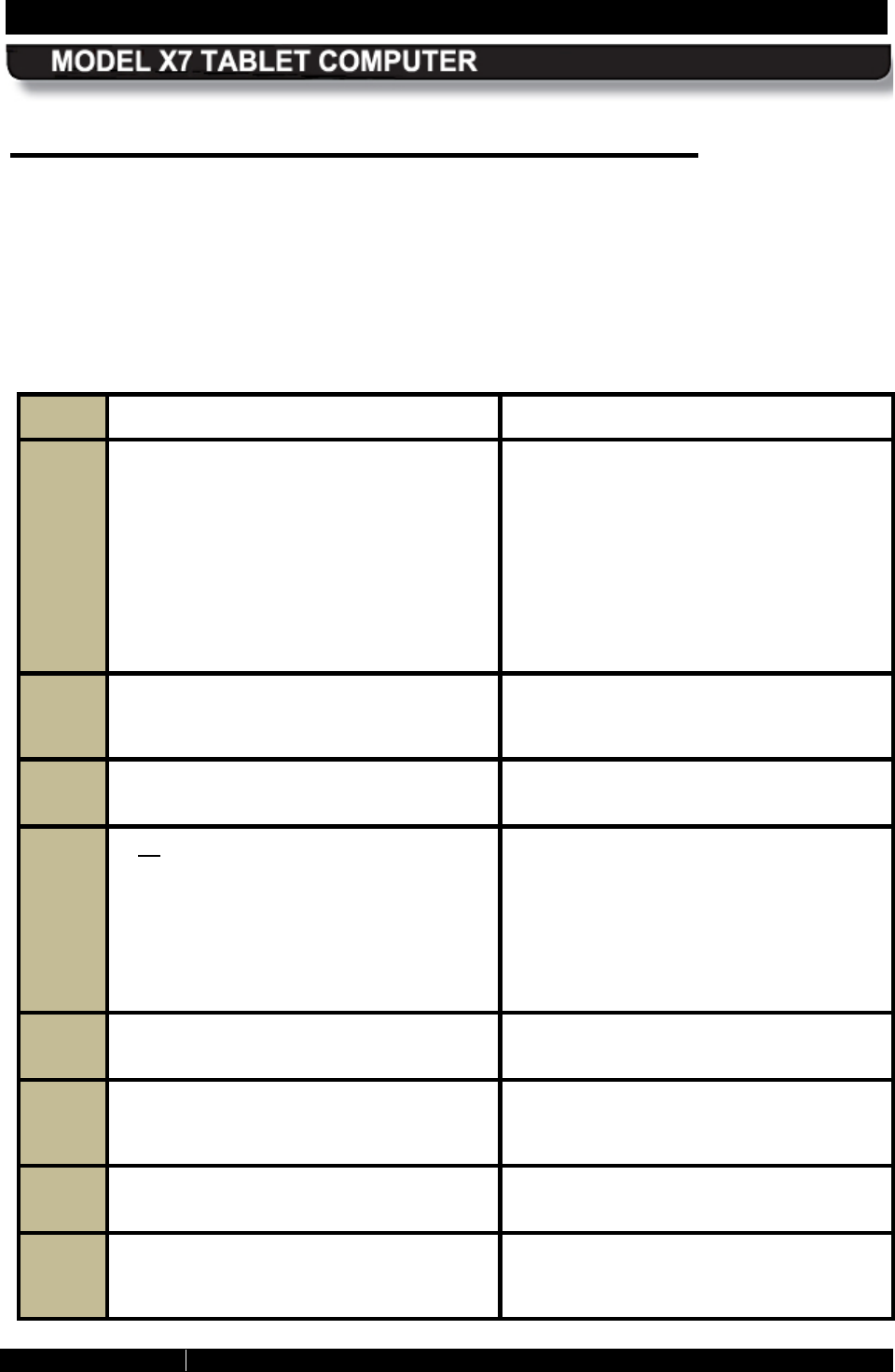
SECTION 4 NETWORKING PAGE 92
9711-26400-0001
EXPORT CONTROLLED – SEE PAGE 3
Rev A
Managing your E thernet Connection
Your X7 supports a cabled 10/100 Ethernet connection through a desk dock or a vehicle dock
using a USB to LAN converter chip located in the docking station breakout box. An RJ45
Ethernet connector is provided at the breakout box for physical connection to the Ethernet LAN.
Once your docking station is cabled into the network, follow the procedure in Table 15 to
connect to the LAN.
Table 15. Setting up an Ethernet Connection
STEP ACTION COMMENTS
1.
C
ontact your IT department or internet
provider to
obtain a user name and
password.
If necessary, your internet provider will
give you an IP address as well.
Otherwise, the IP address
will be
provided automatically by the network
once you are physically connected and
the X7 is running.
2.
Click on Start
à
Control Panel
à
Network and Internet
à
Network and
Sharing Center.
This will open the Network and Sharing
Center window as shown in Figure 41.
3.
Click on the Change Adapter Settings
link in the left-hand navigation panel. This will open the Network Connections
window.
4.
If no red “X” appears next to the Local
Area Connection
icon, your external
LAN connection is established and you
can open an internet browser to access
the internet.
If there is a red “X” showing, go to Step
5.
5.
Click on the “back” arrow to return to the
Network and Sharing Center window.
6.
In the Change Your Network Settings
panel, click on the
Set Up a New
Connection or Network link.
7.
Highlight the Connect to the Internet
option and click on Next. The Connect to the Internet window will
open.
8.
Click on the Broadband connection
option.
An information dialog window will open
with entry fields for your service provider,
as shown in Figure 45.
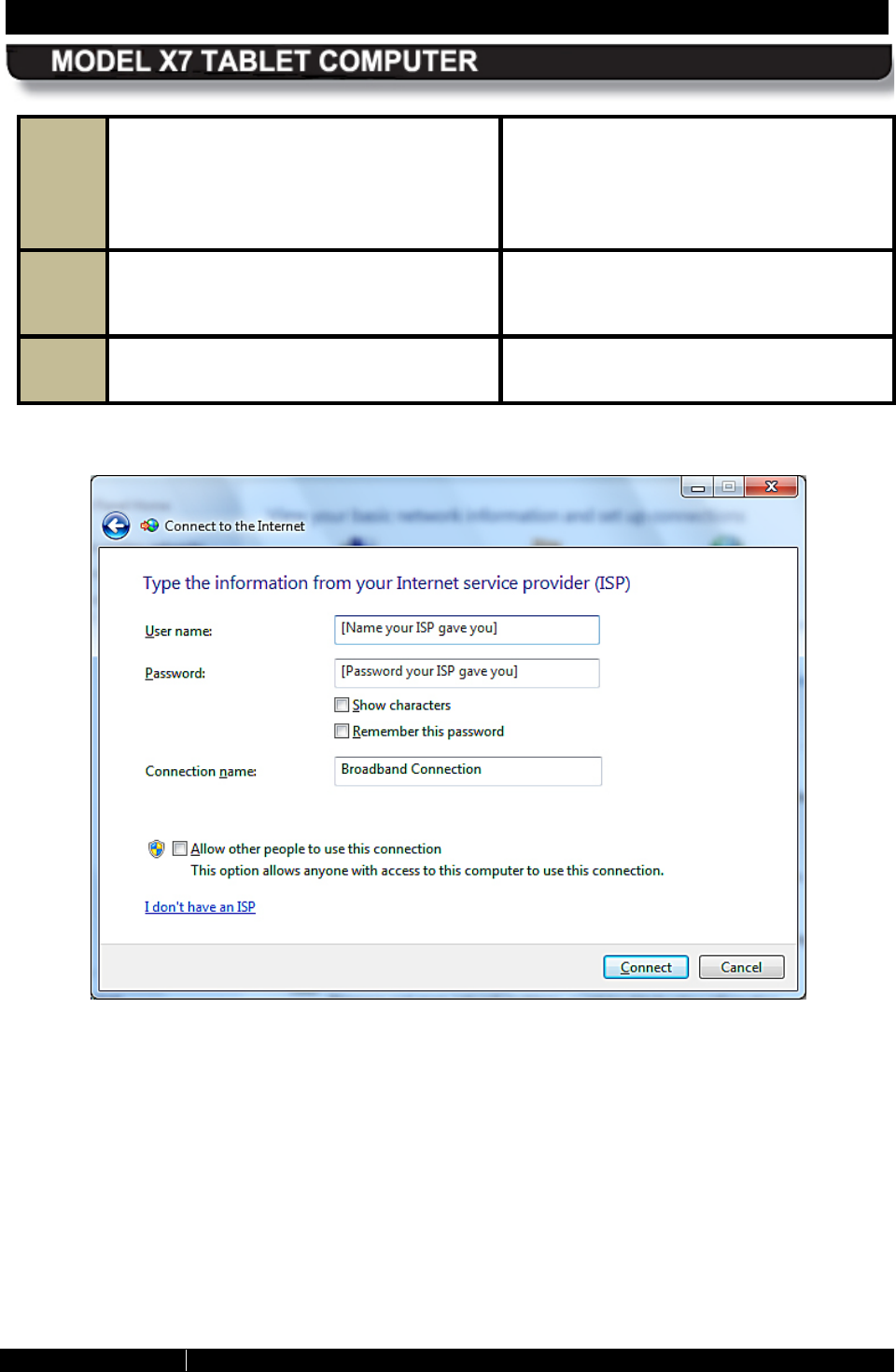
SECTION 4 NETWORKING PAGE 93
9711-26400-0001
EXPORT CONTROLLED – SEE PAGE 3
Rev A
9.
Enter your user name and password in
the fields provided.
Click on the
Remember this Password option if you
don’t want to have to enter the password
each time you access the network.
10.
Enter the IP address provided by your IT
department or internet service provider
in the Connection Name field.
If the address is already showing, you do
not have to enter it again.
11.
Click on the Connect button.
A message window will pop up stating
that your connection was successful.
Figure 45. Internet Service Provider Information Window
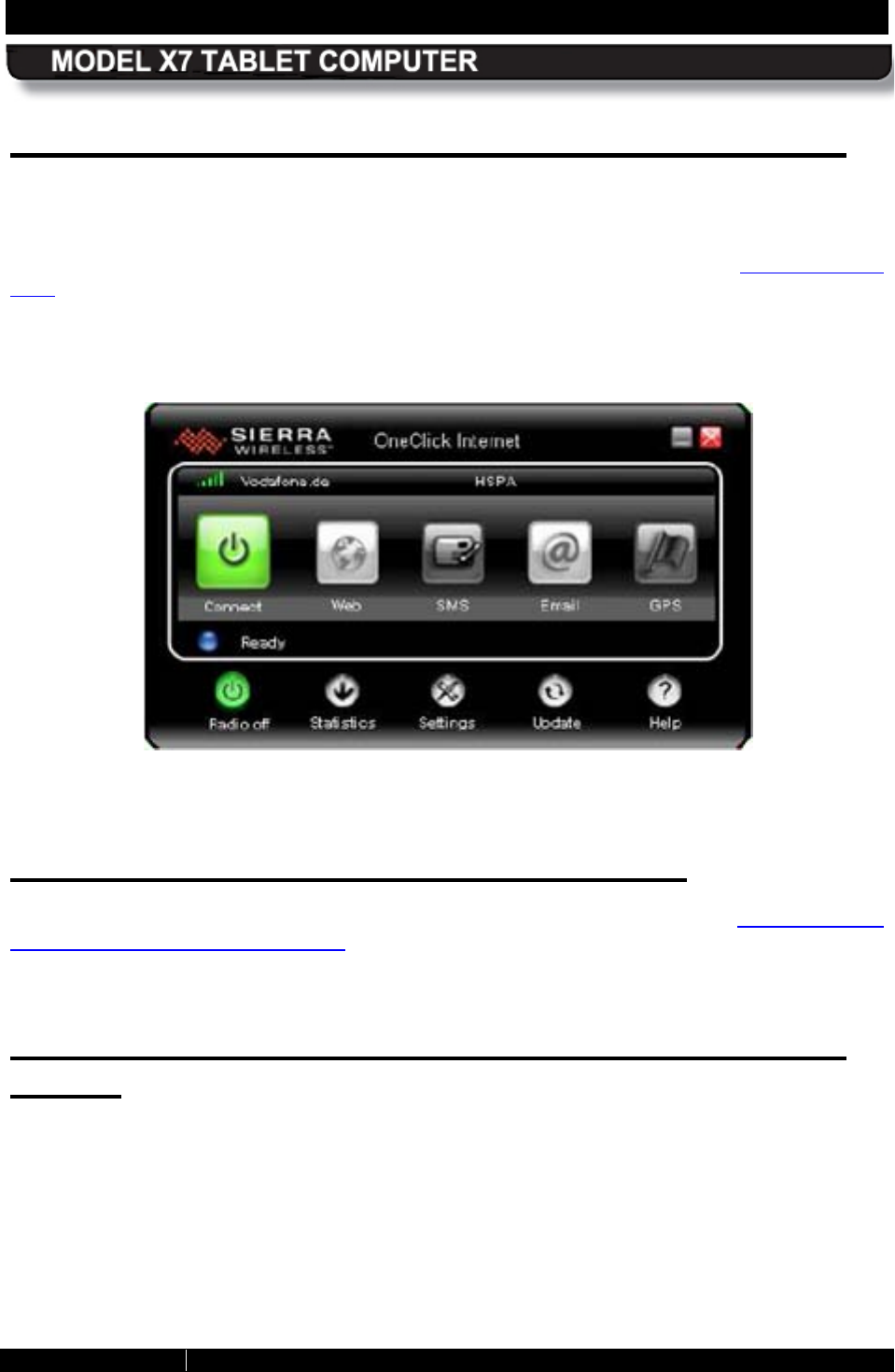
SECTION 4 NETWORKING PAGE 94
9711-26400-0001
EXPORT CONTROLLED – SEE PAGE 3
Rev A
Activating the Optional Gobi® WWAN Radio
If you have the Gobi® WWAN radio installed, your hardware is already configured. However, for
certain providers, you must install a valid SIM card (Figure 13) before you can connect to their
network. The SIM card is obtained from your WWAN service provider and is installed in a socket
located inside the X7. Once you obtain your SIM card, follow the procedure in Installing a SIM
Card.
.Once your SIM card is installed (or if you don’t need one) click on the OneClickInternet icon
on the desktop to open the connection manager, as shown in Figure 46.
Figure 46. Sierra® OneClickInternet™ Connection Manager
Us ing the OneC lickInternet Application
For instructions on how to use the OneClickInternet application, refer to the Sierra OneClick
Connection Manager User Manual which is included in Appendix C. NOTE: The Sierra
OneClickInternet application is already installed on your computer so you can skip the
installation instructions in Section 1 of the manual.
Us ing the Network Driver Interface Specification
(NDIS )
NDIS is an application programming interface (API) that provides an additional layer of control
to your Sierra® OneClickInternet™ connection manager. It allows your Gobi radio to
automatically connect to your provider after powering up the computer without starting the
OneClick Internet application and before you log in. However, when you first receive your
ARMOR X7, NDIS is not automatically available and must be manually configured in order to
use it.
Follow the procedure in Table 16 to enable NDIS in your Sierra OneClick Internet connection
manager.
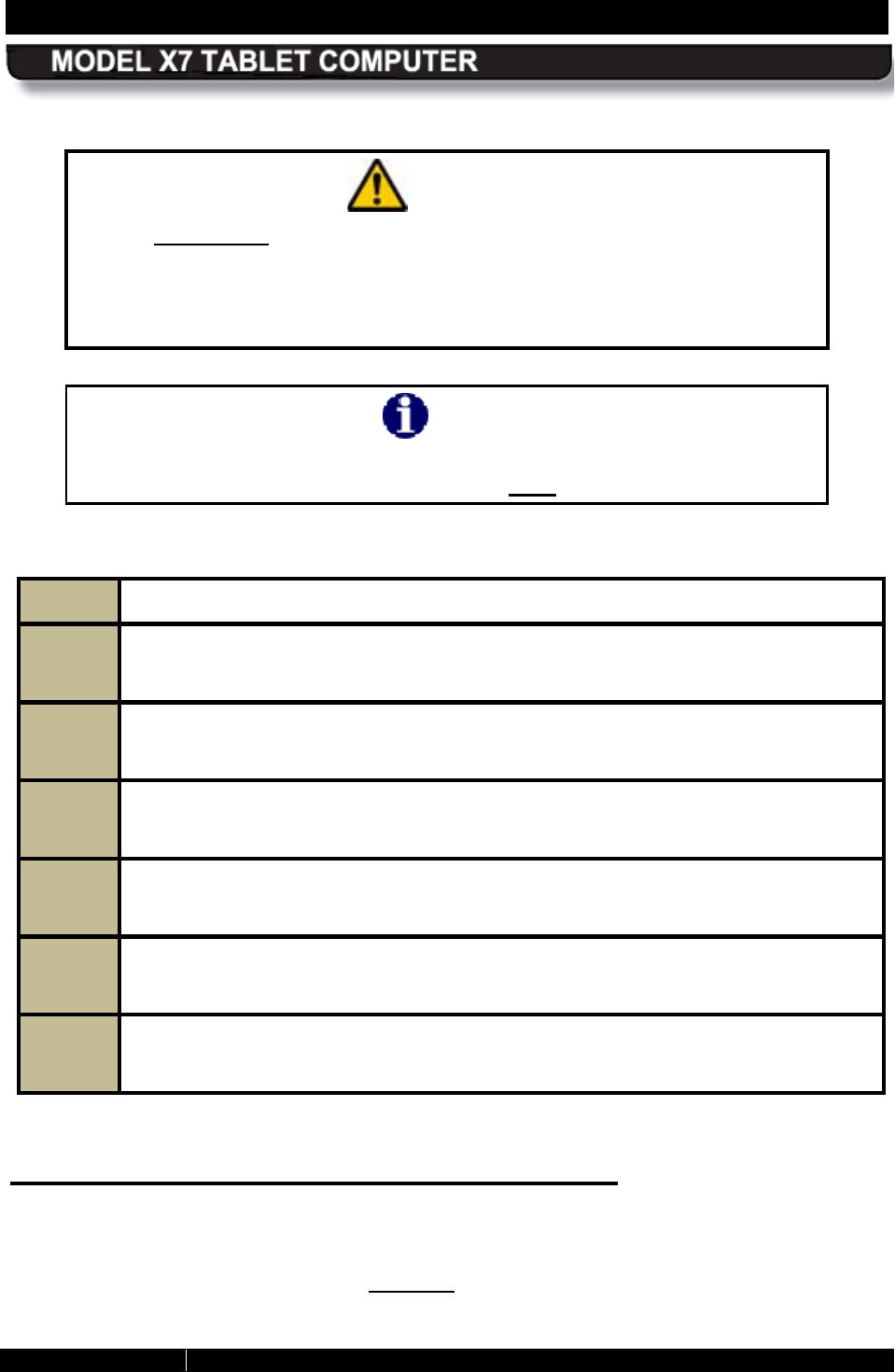
SECTION 4 NETWORKING PAGE 95
9711-26400-0001
EXPORT CONTROLLED – SEE PAGE 3
Rev A
CAUTION!
Before uninstalling the OneClickInternet application with NDIS enabled,
make sure that the “Gobi NDIS Auto Connect” option is unchecked in the
Settings/General tab. Otherwise
the module will always connect
automatically on the next start up. Without the OneClickInternet application
installed, you cannot disable this feature.
NOTE
It is recommended that you test the profile that you will use with the NDIS
auto connect feature to ensure that it works prior to enabling NDIS.
Table 16. Configuring the Sierra OneClick Application to Use NDIS
STEP
ACTION
1. If open, close the OneClick connection manager.
2. Use Windows Explorer to navigate to the C:\Program Files (x86)\OneClickInternet
folder.
3. Double-click on the Config.ini file to open the file with Notepad (you can use any
text editor).
4. Add the following line: AutoNDISConnect=1
5. Save the file and exit.
6. In the Sierra OneClickInternet application, click on the Settings button and select
the General tab. Check the “Gobi NDIS Auto Connect” option.
Important Notes about Us ing NDIS :
• NDIS turns the WWAN radio on even before the OS starts. This is not always a
desirable state, so choose NDIS only if you need this functionality.
• NDIS enables the Gobi WWAN hardware to connect, reconnect and roam automatically,
so these connection options on the Settings page are ignored if chosen in conjunction
with NDIS.
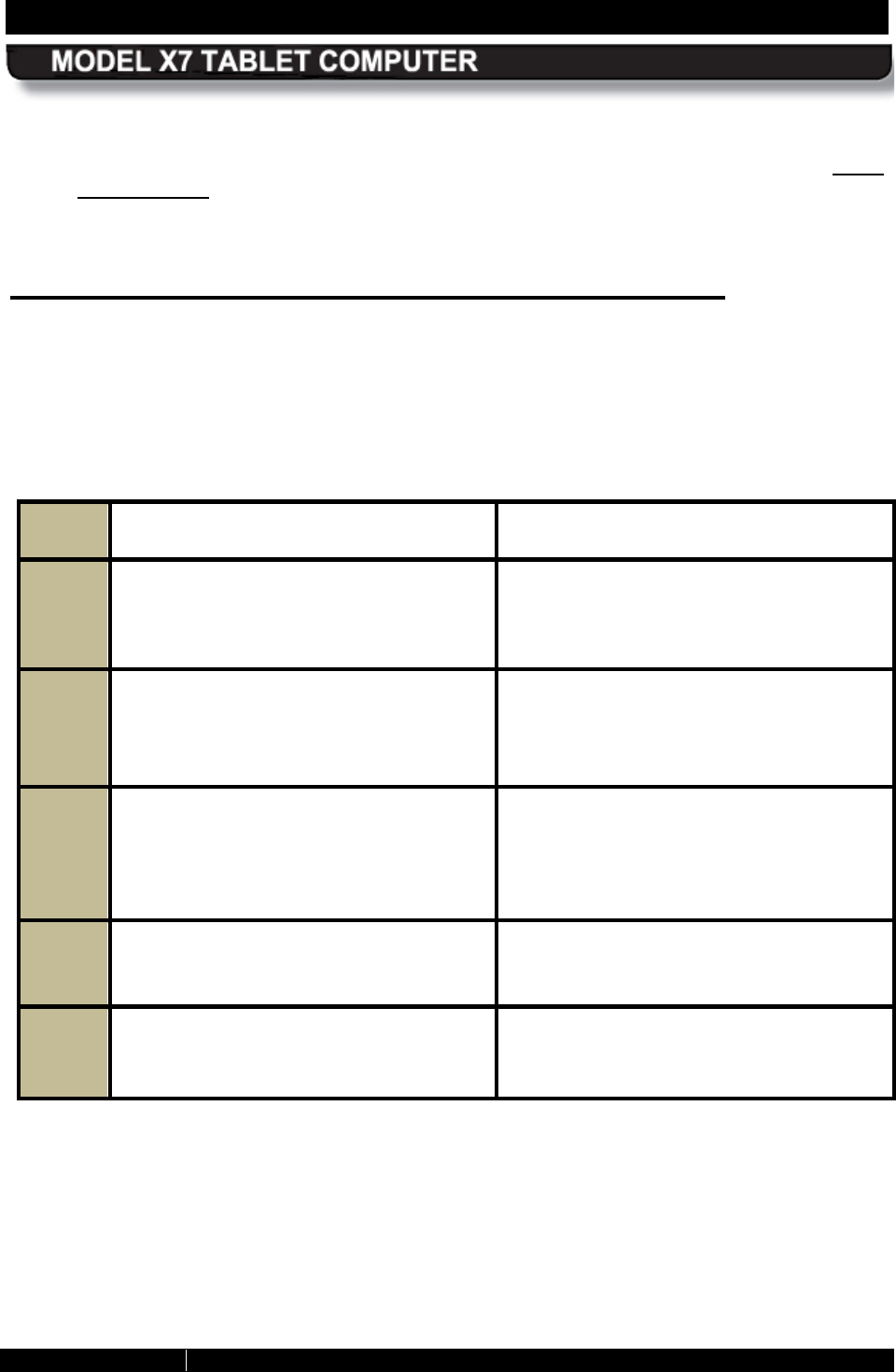
SECTION 4 NETWORKING PAGE 96
9711-26400-0001
EXPORT CONTROLLED – SEE PAGE 3
Rev A
• If you reboot the computer, NDIS will maintain your connection during the reboot.
• Selecting the “Auto Launch” option on the Settings page when NDIS is selected is not
recommended as this will launch the OneClickInternet application upon reboot which will
restart your connection.
Activating the Optional GPS R eceiver
The u-blox ® u-center™ GPS control application is bundled with your X7 software suite. Before
you can use the application, however, you must manually obtain and enter the communications
(COM) port that was assigned to the u-center program by Windows when the operating system
was installed. To do this, follow the procedure in Table 17.
Table 17. Configuring the u-Center Com Port
Step Action Comment
1. From the Windows desktop, select the
Start button and select
Control Panel
à
Hardware and Sound
à
Devices
and Printers
à
Device Manager
The Device Manager dialog window will
open.
2. Open the Ports (COM & LPT) option,
scroll down to u-blox
5 GPS and
GALILEO Receiver
and record the
COM port number.
3. Close the Control Panel and open the u-
center application by double-clicking on
the u-center desktop icon or selecting
the u-center option from the All
Programs list.
The u-
center application window opens
as shown in Figure 47. NOTE: The
application workspace is configurable
and may not look exactly as in the figure.
4. Select the Receiver
menu in the
application tool bar and click on the
Port option.
5. Choose the COM port that you recorded
from Control Panel.
Your GPS receiver will automatically
begin searching for satellites.
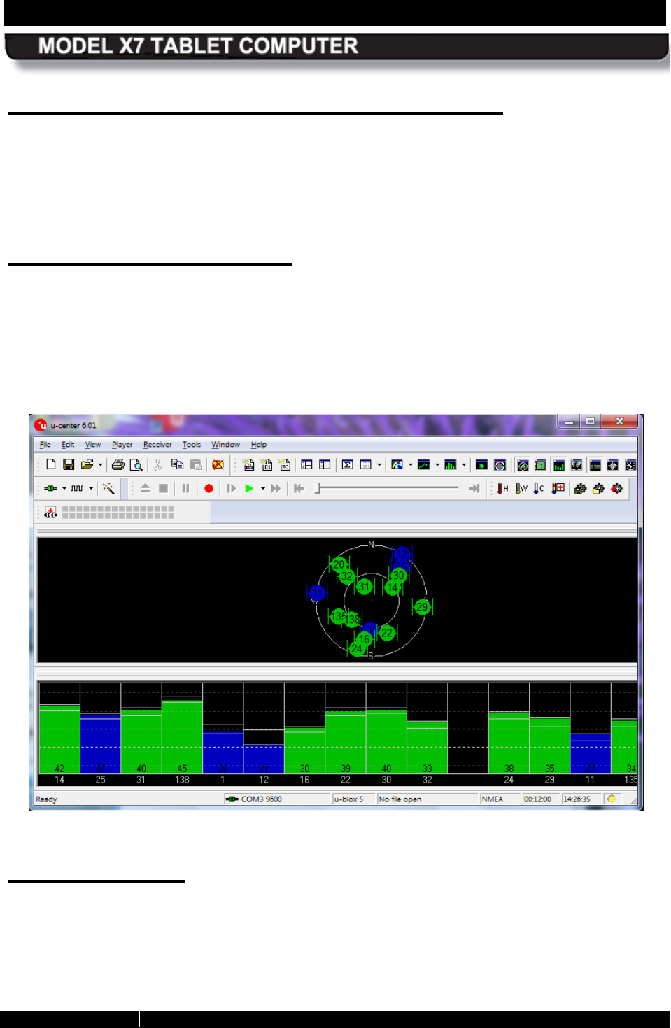
SECTION 4 NETWORKING PAGE 97
9711-26400-0001
EXPORT CONTROLLED – SEE PAGE 3
Rev A
The u-center GPS Application Window
The diagram in the center shows the approximate positions of satellites relative to your location
that are within range of the receiver. The graph at the bottom of the page shows the signal
strength of each satellite. A green bar indicates acceptable signal strength; a blue bar indicates
marginal reception. You must have at least four satellites with acceptable signal strength to
generate reliable position data.
u-center User’s Guide
A complete description of the u-center software is beyond the scope of this manual. However,
an online User’s Guide is provided with your u-blox installation. To access the user’s guide,
select Start à Computer à Local Disk (C:) à Programs Files (x86) à u-blox à u-center
à Documentation à User’s Guides and double-click on the u-Center_User_Guide pdf file.
NOTE: We recommend you create a shortcut to this file on the desktop.
Figure 47. U-Center GPS Application Window
Assisted GPS
Assisted GPS (AGPS) is an option that uses your wireless network connection to quickly
download the GPS almanac and ephemeris information your system needs to compute a first fix
on your location. This greatly reduces the time to first fix (TTFF).
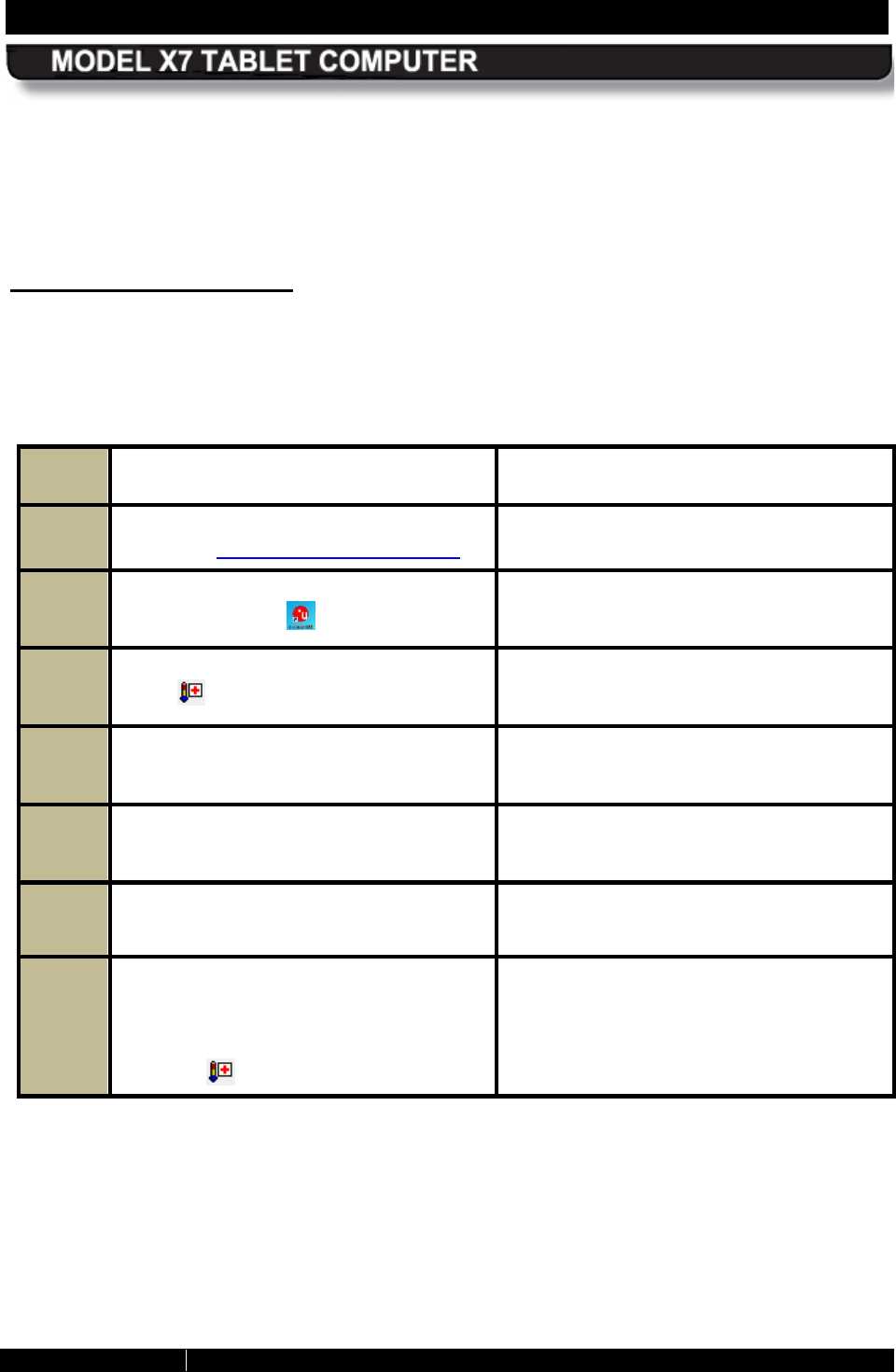
SECTION 4 NETWORKING PAGE 98
9711-26400-0001
EXPORT CONTROLLED – SEE PAGE 3
Rev A
With AGPS, your system can acquire an accurate fix in less than 30 seconds. Without AGPS,
the TTFF can take as long as 15 minutes depending on surrounding structures and the strength
of the satellite signals.
However, AGPS depends on an internet connection so it is limited to areas where wireless
network coverage is available.
Ac tivating As s is ted G P S
AGPS is free with your purchase of your ARMOR X7 but you must obtain the necessary AGPS
password from u-blox by following the procedure in Table 18.
Table 18. Obtaining the AGPS Password from u-blox
Step Action Comment
1.
Send an email with
no subject or
content to agps-account@u-blox.com Within 24 hours, u-
blox will return a
password via your email account.
2. Once you have your password, click on
the u-center icon on the desktop.
The u-
center application window opens
as illustrated in Figure 47.
3. Locate the thermometer icon with a red
cross and click on it.
The AssistNow Online™ window opens,
as shown in Figure 48.
4. Enter your email address in the User
field.
5.
Enter your AGPS password in the
Password field.
6. Click OK to save and exit.
7.
When you want to use the assisted
GPS capability, ensure you have a valid
wireless connection to the internet and
click on the thermometer icon with the
red cross .
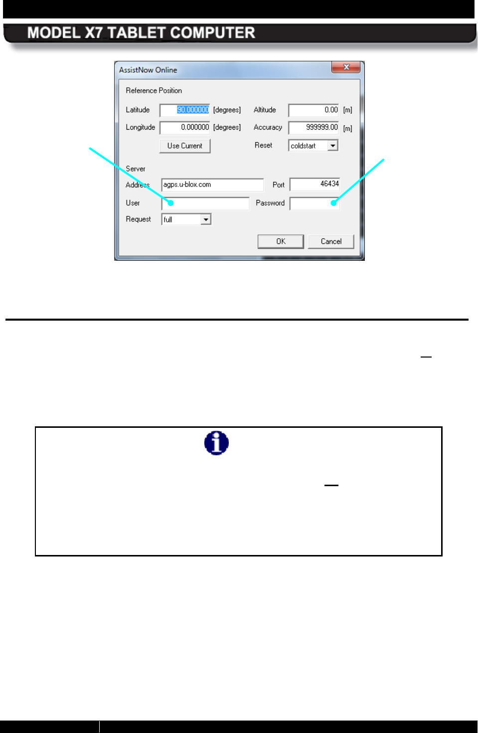
SECTION 4 NETWORKING PAGE 99
9711-26400-0001
EXPORT CONTROLLED – SEE PAGE 3
Rev A
Figure 48. u-center AssistNow Online Window
Enabling and Disabling Your Wireless R adios
You may wish to turn off one or more of your radios to save power, to avoid interfering with
other radio systems, or just to ensure your privacy. Or you may want to turn off all of your
installed radios at one time but keep working on your computer, as when travelling on an
aircraft.
Follow the procedure in Table 19 to enable/disable your radios.
NOTE
If you exit ARMORutils completely or shut down your system with the
Radios ON/OFF Toggle set to OFF, all radios will be off the next time you
restart ARMORutils or turn on your computer. This is done for safety
reasons to prevent your wireless radios from being accidentally re-
activated during flight.
You will need to re-enable each radio with its Radio ON/OFF button when
you reach your destination.
ENTER YOUR
EMAIL ADDRESS
HERE
ENTER YOUR
AGPS
PASSWORD
HERE
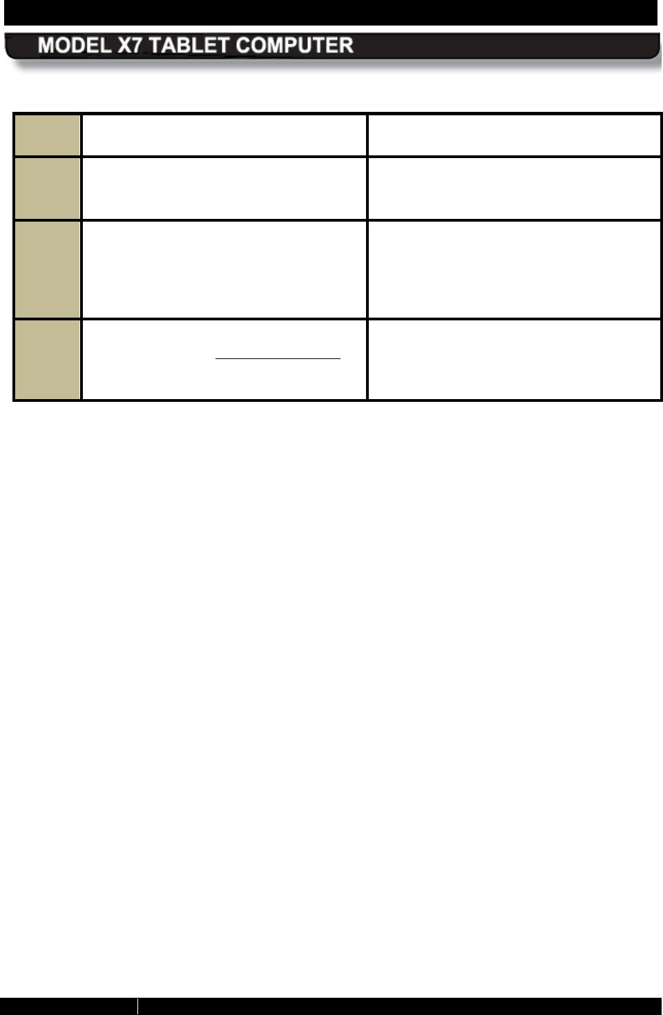
SECTION 4 NETWORKING PAGE 100
9711-26400-0001
EXPORT CONTROLLED – SEE PAGE 3
Rev A
Table 19. Enabling and Disabling Your Wireless Radios
Step Action Comment
1.
Click on the ARMORutils icon on the
desktop and select the Wireless Setup
option.
This will open the Wireless Setup dialog
window, as shown in Figure 53.
2. Click on the ON or Off
button to
enable/disable each installed radio that
you want to control then click the Save
Settings
button to save your
configuration.
3. Click on the Radios ON/OFF Toggle
button to turn off all enabled radios at
one time. Click it again to turn them all
back on.
SECTION 4 NETWORKING PAGE 101
9711-26400-0001
EXPORT CONTROLLED – SEE PAGE 3
Rev A
Wireles s S ignal Quality
Wireless signal quality is affected by several conditions:
• Distance from a Wi-Fi access point.
• Access rights (set up through an administrator).
• Your security settings.
• Orientation of the wireless antennas.
If you are having difficulty connecting to your network, try the following steps:
1. Open the Wireless Setup page in ARMORutils and verify that the radio is enabled.
2. If your tablet is not locked in a vehicle mount, try turning the unit in various directions to
improve signal quality.
3. Try to get closer to the access point.
4. Move away from obstacles such as trees and metal objects which may be between you
and the Access Point.
5. Verify that the Wi-Fi access point is operating.
6. If none of these actions solves the problem, contact your Network Administrator for
assistance.
Us ing your R adios with an X7 Vehicle
Docking S tation
With the X7 vehicle dock (see Vehicle Dock), you can switch your GPS receiver and/or WLAN
radio to externally mounted antennas for improved operation. By using external antennas, you
can reduce the attenuating effects of the vehicle cab and the constantly changing direction of
the X7 internal antennas.
When configured in ARMORutils, the RF multiplexer in the X7 will automatically switch the GPS
receiver, WLAN radio or both to the external antennas whenever the tablet is docked, and
switch them back to the internal antennas when the tablet is undocked.
Follow the instructions in Table 20 to configure your radios to use external antennas.
NOTE
If you have a vehicle dock but are not
connected to external
antennas, you must set the Dock RF Sw
in the ARMORutils
Wireless Setup dialog window to “Disable” in order to use the
tablet’s internal antennas.
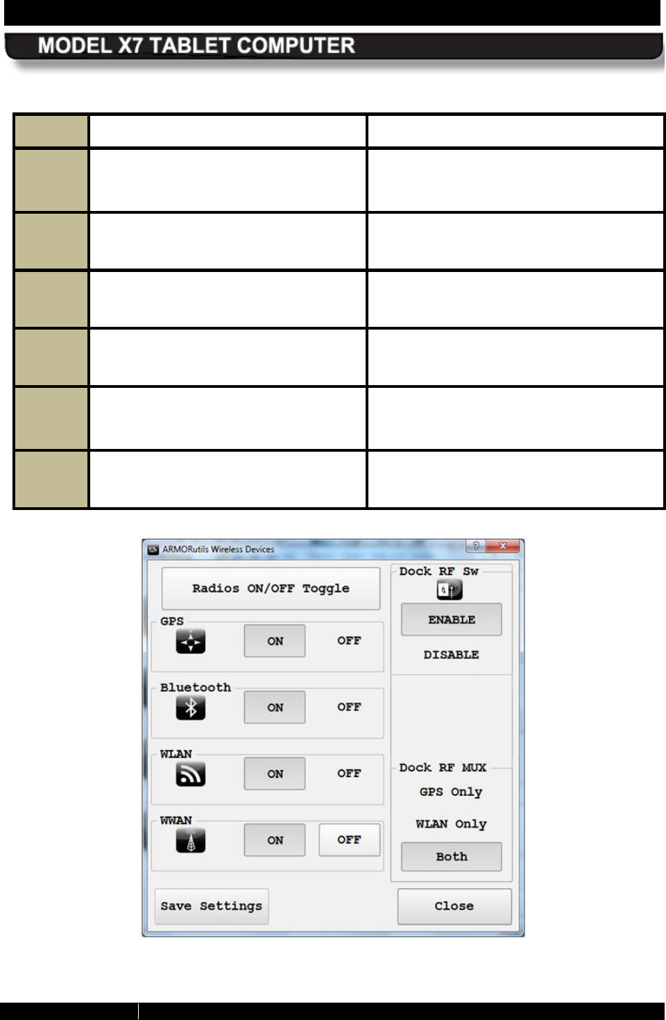
SECTION 4 NETWORKING PAGE 102
9711-26400-0001
EXPORT CONTROLLED – SEE PAGE 3
Rev A
Table 20. Configuring the X7 to use External Antennas
STEP
ACTION CONDITION OR INDICATION
1.
Place the X7 in the docking cradle
(see Figure 18) and press down on the
top clamp until it locks.
2. Double-
click on the ARMORutils icon
in the systray. The ARMORutils Main Window opens.
3. Click on the Wireless Setup option. The Wireless Setup dialog window opens
as shown in Figure 49.
4. In the Dock RF MUX
panel, select
GPS Only, WLAN Only or Both. The default setting is “Both”.
5. Press the Docking RF Sw Enable
button to enable
switching of the
selected antennas.
If the Docking RF Sw is set to “Disable”,
the tablet will utilize it’s internal antennas.
6. Click on the Save Settings button to
save your changes.
Figure 49. ARMORutils Wireless Setup Dialog
SECTION 5 YOUR ARMOR X7 SOFTWARE PAGE 103
9711-26400-0001
EXPORT CONTROLLED – SEE PAGE 3
Rev A
Table of Contents List of Figures List of Tables Acronyms Glossary
5. YOUR ARMOR X7 SOFTWARE
Your ARMOR X10gx comes with a variety of software applications. Many of these are standard
with your particular operating system, some are necessary to configure and operate your
system, some are required for specific devices or functions and some are complementary
applications provided by DRS to enhance your X10gx experience.
The following paragraphs provide an overview of the key programs and utilities necessary to
configure and operate your X7 computer. Some of these applications are required for specific
devices or functions and some are complementary applications provided by DRS to enhance
your X7 experience. Many of these are standard with the Windows 7 operating system.
NOTE
A detailed description of each application’s settings and options (with the
exception of the ARMORutils application provided by DRS) is beyond the
scope of this manual. Please refer to the Windows Help resources and to
the help resources provided with each software application.
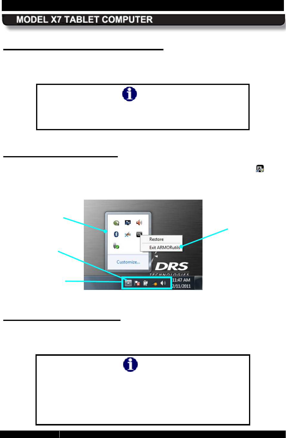
SECTION 5 YOUR ARMOR X7 SOFTWARE PAGE 104
9711-26400-0001
EXPORT CONTROLLED – SEE PAGE 3
Rev A
ARMORutils™ Application
The ARMORutils application is provided to help you configure and manage your X7 computer. It
contains settings and information about screen setup, wireless configuration, battery status and
much more.
NOTE
The screen images in this section are used for reference only and
may not reflect the exact operating system or actual
configuration of your X7.
S tarting AR MOR utils
ARMORutils starts automatically when you boot up your computer and places an icon in the
system application tray (systray) located in the lower right corner of the task bar (see Figure 50).
An icon is also provided on the desktop and ARMORutils appears in the Windows Start menu
All Programs list so you can restart ARMORutils should you exit it for any reason.
Figure 50. Systray with Overflow Menu Displayed
Opening AR MOR utils
To open the ARMORutils Main dialog window (Figure 51), double-click on the ARMORutils icon
in the systray or right-click on the icon and select Restore (NOTE: If the icon is not visible in the
systray, click on the menu “up” arrow to access the overflow menu).
NOTE
Armor Utilities must be run by a user with Administrator
privileges due to the User Account Code restrictions in Windows
7. If you are not using an account with administrator privileges,
Windows will display a password entry window
when you try to
run ARMORutils. You must enter the Administrator password to
proceed.
SYSTRAY
OVERFLOW
MENU
SYSTRAY
ARMORUTILS
EXIT OPTION
SYSTRAY
MENU UP
ARROW
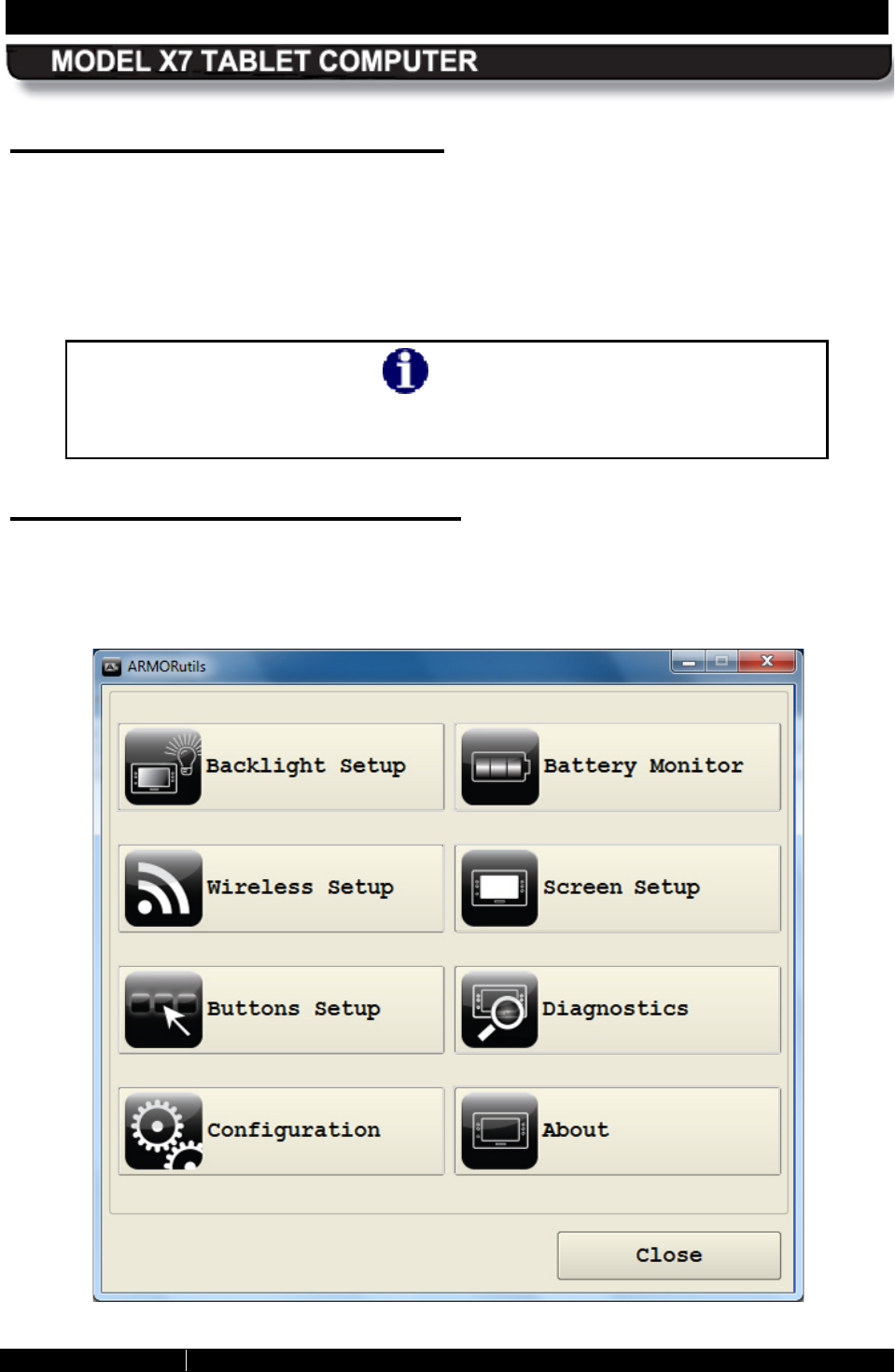
SECTION 5 YOUR ARMOR X7 SOFTWARE PAGE 105
9711-26400-0001
EXPORT CONTROLLED – SEE PAGE 3
Rev A
E xiting from AR MOR utils
When you click on the CLOSE button on the ARMORutils main window or click on the red “X” at
the upper right corner, you are only closing the main window – you are not exiting from the
utility. ARMORutils continues to run in the background.
To exit from the application completely, right-click on the ARMORutils icon in systray and select
Exit ARMORutils. You can restart the application by clicking on the ARMORutils icon on the
desktop or select the ARMORutils option in the Start menu Programs list.
NOTE
If you exit ARMORutils completely, you will lose programmable button
functionality. Restart ARMORutils to reactivate the PBs.
AR MOR utils Main Window
The ARMORutils main window is shown in Figure 51. Eight options provide access to dialog or
information windows. Click on an option to access one of these windows.
Figure 51. ARMORutils Main Window
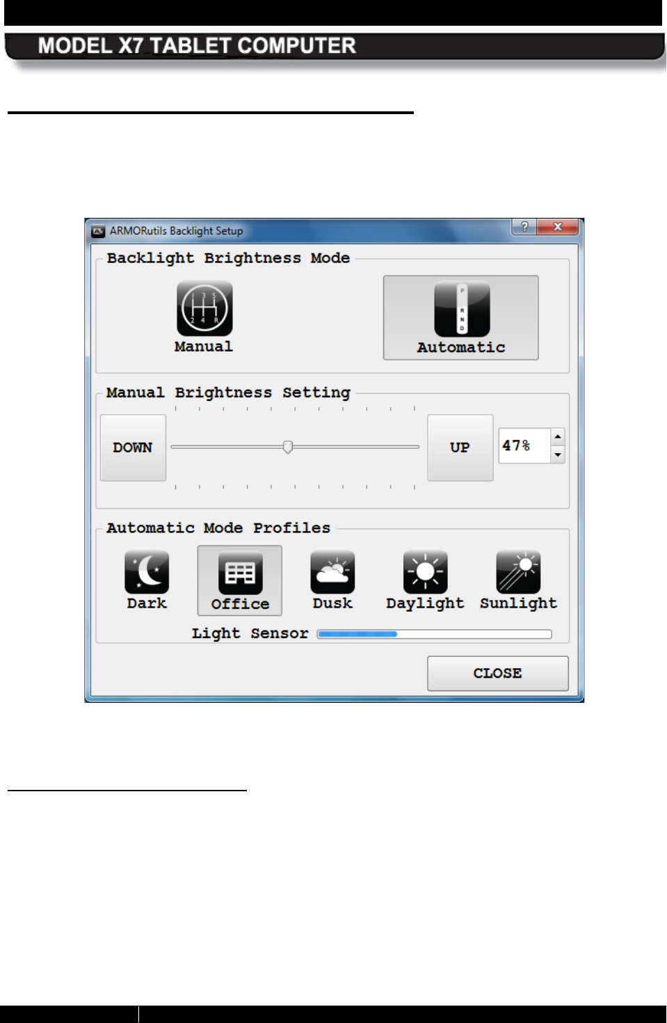
SECTION 5 YOUR ARMOR X7 SOFTWARE PAGE 106
9711-26400-0001
EXPORT CONTROLLED – SEE PAGE 3
Rev A
B acklight S etup Dialog Window
The Backlight Setup dialog window allows you to adjust the screen brightness manually or
automatically and to select from a series of preset profiles to automatically restrict the
brightness range under specific lighting conditions.
Figure 52. ARMORutils Backlight Setup Dialog
Automatic B rightnes s Mode
The Automatic brightness mode is initially activated by default. Automatic brightness adjustment
is controlled by the ambient light sensor (ALS) located on the indicator panel on the front of your
X7 tablet. The ALS monitors the surrounding (ambient) light level and automatically adjusts the
backlight level to maintain the same relative screen brightness. For example, if you are working
in an office near a window and someone opens the blinds, the surrounding light will suddenly
increase. The ALS will measure the increase in light level and automatically increase your
screen and indicator brightness to compensate.
Unlike Manual mode, where you can vary the brightness across the full adjustment range, in
Automatic mode, the total range of brightness adjustment is smaller and is determined by the
selected Automatic Mode Profile.

SECTION 5 YOUR ARMOR X7 SOFTWARE PAGE 107
9711-26400-0001
EXPORT CONTROLLED – SEE PAGE 3
Rev A
Automatic Brightness Mode Profiles
Everyone’s eyes react differently to changes in light levels and there may be times when a
particular range of automatic brightness adjustment is uncomfortable for you.
You can tailor the automatic brightness adjustment by selecting one of the 5 pre-configured
brightness profiles: Dark, Office, Dusk, Daylight, and Sunlight. These profiles control the range
of brightness levels to values based on typical surroundings or times of day.
For example, if you typically work in an office environment but the automatic brightness doesn’t
make the display bright enough for you, you can select the Dusk, Daylight or Sunlight profile to
increase the brightness range proportionally. Similarly, if the normal brightness control results in
displays that are too bright, you can select the Office or Dark profile to reduce the brightness
range.
When you first start ARMORutils, the system defaults to the Office profile. Once you select a
different profile, the tablet will continue to use that profile until you select another.
Manual B rightnes s Mode
Click on the Manual button to activate the automatic brightness control mode. To manually
adjust screen brightness, click repeatedly on the UP or DOWN buttons in the Manual Brightness
Setting panel or drag the slider. The current brightness level is displayed as a percentage in the
window to the right of the UP button. You can also adjust the brightness by clicking on the up
and down arrows next to the percentage readout.
The manual controls change the brightness from 0% to 100% of the total available adjustment
range for Manual mode. At the 0% point, the brightness low but the screen is not totally dark.
Switching B etween Brightnes s Modes
If you are in Manual mode and you click on one of the automatic profile settings, the brightness
mode will switch to Automatic mode. Conversely, if you are in Automatic mode and click on the
Manual mode UP or DOWN button, or one of the up/down arrows, the brightness mode will
switch to Manual mode.
Light Sensor B ar
The Light Sensor bar provides a visual indication that the ALS circuit is functioning correctly.
Screen brightness changes in response to the changing ambient light level will occur gradually
to allow your eyes to adjust and may not be readily apparent, but the Light Sensor bar gives an
immediate indication that the ALS is controlling the screen brightness. The Light Sensor bar will
continue to operate even when the backlight mode is set to Manual.
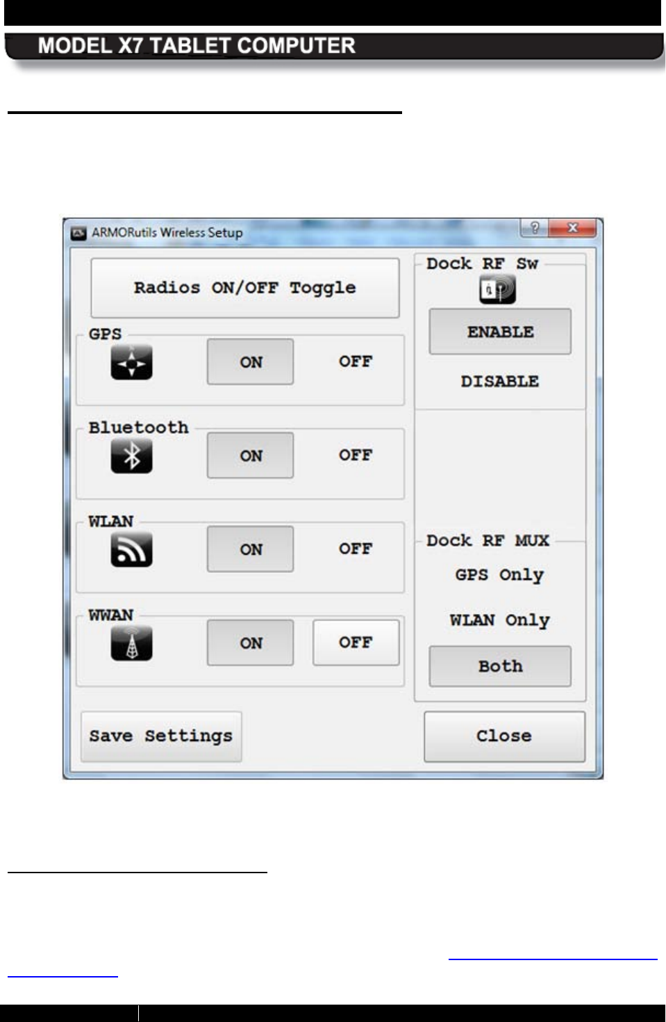
SECTION 5 YOUR ARMOR X7 SOFTWARE PAGE 108
9711-26400-0001
EXPORT CONTROLLED – SEE PAGE 3
Rev A
Wireless S etup Dialog Window
The Wireless Setup dialog allows you to enable or disable each wireless radio installed in your
ARMOR X7. It also provides controls for external antennas connected through an X7 vehicle
dock.
Figure 53. ARMORutils Wireless Setup Dialog
R adios ON/OFF Toggle Button
This button allows you to turn off or turn on all radios currently enabled with the Radio ON/Off
buttons. This is particularly handy if you’re on a commercial aircraft and you want to turn off all
your enabled radios so you can continue working with the computer without causing
interference with the aircraft’s electronic systems. Refer to Enabling and Disabling Your
Wireless Radios for information on how to use this button.
SECTION 5 YOUR ARMOR X7 SOFTWARE PAGE 109
9711-26400-0001
EXPORT CONTROLLED – SEE PAGE 3
Rev A
R adio ON/OFF B uttons .
There is an ON and an Off button for each radio that is installed or supported. When you first
start your ARMOR X7, all installed radios are ON or enabled (default condition). Each radio can
then be disabled by pressing its OFF button and re-enabled by pressing its ON button. Refer to
Enabling and Disabling Your Wireless Radios for information on how to use these buttons.
NOTE: Radio options that may be available but are not installed will appear here also.
Dock R F S w B utton
The Dock RF Sw button enables or disables the antenna configuration that is selected by the
Dock RF Mux switch. The initial setting for the Dock RF switch is “Enable”. If the switch is set to
“Disable”, a docked tablet will use its internal antennas. NOTE: If the X7 does not sense a
vehicle dock, it will utilize its internal antennas regardless of the setting of the Dock RF Sw.
Dock R F MUX S witch
Your X7 contains an RF multiplexer circuit that is configured by the Dock RF Mux switch. There
are two RF coaxial connectors built into the base of the X7 dock: one for an external GPS
antenna and one for a WLAN (Wi-Fi) antenna (see Vehicle Dock). Depending on the setting of
the Dock RF Mux switch, the RF multiplexer will automatically switch your GPS and/or WLAN
antennas to external antennas mounted on the vehicle whenever you dock the tablet.
You can select GPS only, WLAN only, or Both antennas. The default setting for the Dock RF
MUX switch is “Both”.
S ave S ettings B utton
Regardless of how you configure your radios with the Radio ON/OFF buttons during your
current session, they will return to their previously saved settings the next time you restart the
computer unless you save your current changes. The same is true with any changes to the
Dock RF or Dock RF Mux switches. You must click on the Save Settings button to save any
current changes as your new default settings.
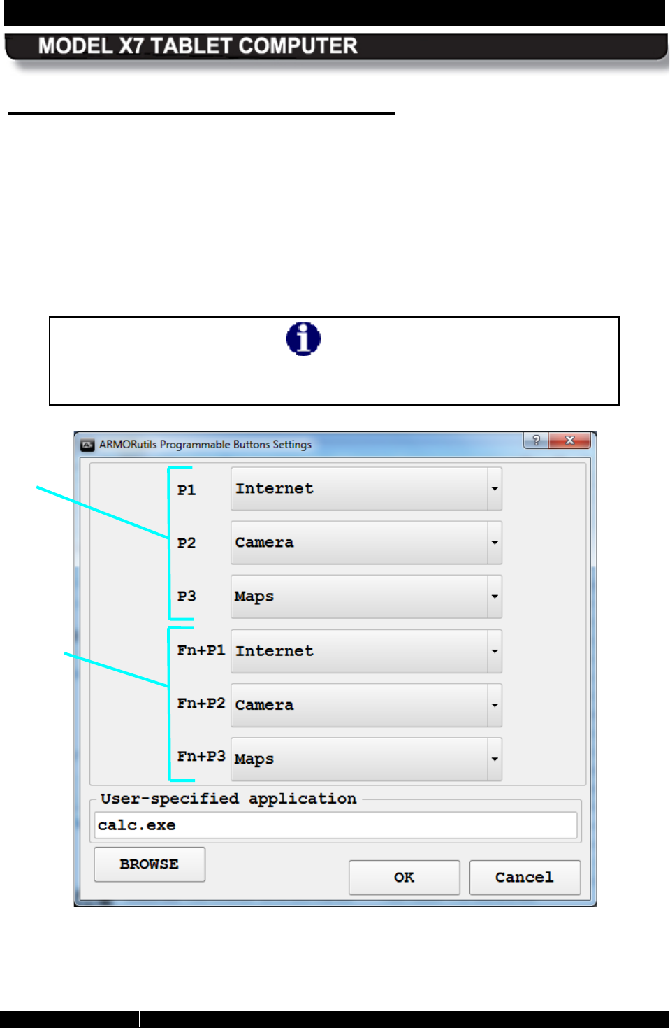
SECTION 5 YOUR ARMOR X7 SOFTWARE PAGE 110
9711-26400-0001
EXPORT CONTROLLED – SEE PAGE 3
Rev A
B uttons S etup Dialog Window
The Buttons Setup dialog window is shown in Figure 54. It allows you to assign two different
functions for each programmable button (or “PB”) labeled P1, P2 and P3. These buttons are
located on the right control panel (see Figure 2).
The first function is activated by pressing and releasing a PB (P1, P2, P3). The second function
is a combo function activated by first pressing and releasing the Fn button and then pressing
and releasing a PB (Fn+P1, Fn+P2, Fn+P3). This provides a total of 6 individual functions that
can be activated using the PBs. The function currently programmed is shown in the field next to
the PB or the PB combo.
NOTE
If you exit ARMORutils completely, you will temporarily lose programmable
button functionality. Restart ARMORutils to reactivate the PBs.
Figure 54. ARMORutils Buttons Settings Dialog
PB
PB
COMBO
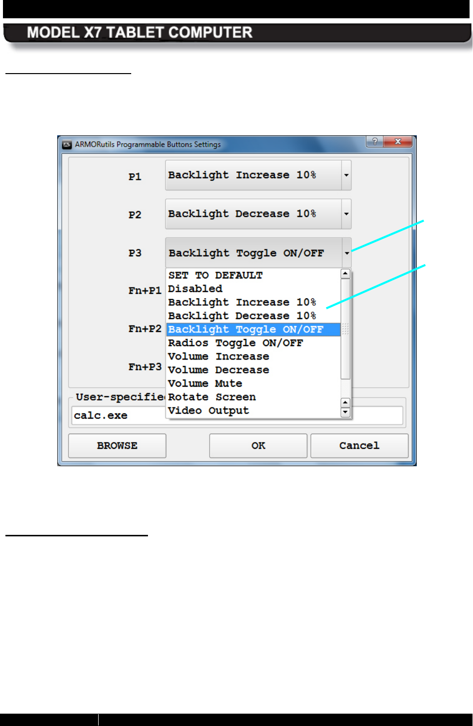
SECTION 5 YOUR ARMOR X7 SOFTWARE PAGE 111
9711-26400-0001
EXPORT CONTROLLED – SEE PAGE 3
Rev A
S electing a F unc tion
Click on the menu arrow next to the PB or PB combo and select the desired function, then click
on the OK button to save your setting. Figure 55 shows a menu opened for the P3 button.
Figure 55. ARMORutils Programmable Button Options Menu
Available PB Functions
The currently available PB functions are listed below along with a brief description of their
purpose (additional functions may be added in future releases of ARMORutils). You can assign
any of these functions to any PB or PB combo.
• Set to Default – Returns the setting to its factory default function.
• Disabled – Disables the button or button combo.
• Backlight Increase 10% - Increases screen and indicator brightness in steps.
• Backlight Decrease 10% - Decreases screen and indicator brightness in steps.
• Backlight Toggle ON/OFF – Toggles the screen on and off.
• Radios Toggle ON/OFF – Toggles all enabled radios on and off.
• Volume Increase – Increases sound volume in steps.
FUNCTION
MENU
MENU
ARROW

SECTION 5 YOUR ARMOR X7 SOFTWARE PAGE 112
9711-26400-0001
EXPORT CONTROLLED – SEE PAGE 3
Rev A
• Volume Decrease – Decreases sound volume in steps.
• Volume Mute – Toggles volume ON or OFF.
• Rotate Screen 90 degrees – Rotates the screen 90 degrees clockwise with each press.
• Video Output Cycle – Not currently supported.
• Sleep/Hibernate – Will place the tablet in Sleep or Hibernate mode.
• Launch User-Specified Application – Allows you to select and launch an installed
application or utility.
• <ENTER> key – Replicates pressing the keyboard “Enter” key
• <UP> key – Replicates pressing the keyboard “Up Arrow” key
• <DOWN> key – Replicates pressing the keyboard “Down Arrow” key
• <PAGE UP> key – Replicates pressing the keyboard “Page Up” key
• <PAGE DOWN> key – Replicates pressing the keyboard “Page Down” key
“S et to Default” F unc tion
Select this function to return a PB or PB combo’s programming to its factory default settings.
The factory default settings for the X7 are:
P1 - Backlight Increase 10%
P2 - Backlight Decrease 10%
P3 - Backlight Toggle ON/OFF
Fn + P1 - Radios Toggle ON/OFF
Fn + P2 - Disabled
Fn + P3 - Disabled
NOTE: You are currently not able to change the PB default settings. If you need to have the
default settings changed, please contact DRS Technical Support.
“Launch User-S pecified Application” F unc tion
Selecting this function enables the User-specified application panel at the bottom of the PB
window. This function allows you to select an executable file to launch an installed application or
utility using a PB or PB combo. You can manually type in the path to the file or hit the BROWSE
button and search for the file in Windows Explorer.
To launch the application, press the assigned PB or PB combo.
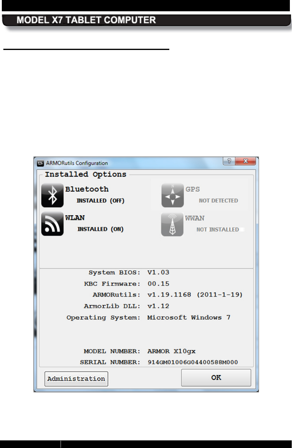
SECTION 5 YOUR ARMOR X7 SOFTWARE PAGE 113
9711-26400-0001
EXPORT CONTROLLED – SEE PAGE 3
Rev A
Configuration Dialog Window
The Configuration Dialog window provides visual confirmation of those wireless radios that are
installed in your X7. If a radio is installed and available, the associated icon and status will
appear in dark contrast. The status of the installed radios is displayed in parentheses next to the
word “Installed”. When the radio is enabled, the status is “ON”. If the radio is disabled, this
status will change to “OFF”.
If a radio is not installed, the status will be “Not Detected” or “Not Installed” and the icon and text
will be grayed out, as illustrated in Figure 56.
The bottom panel of the dialog window lists the current versions of your system BIOS,
ARMORutils and operating system, as well as the ARMOR model number and the unit serial
number.
Figure 56. ARMORutils Configuration Dialog
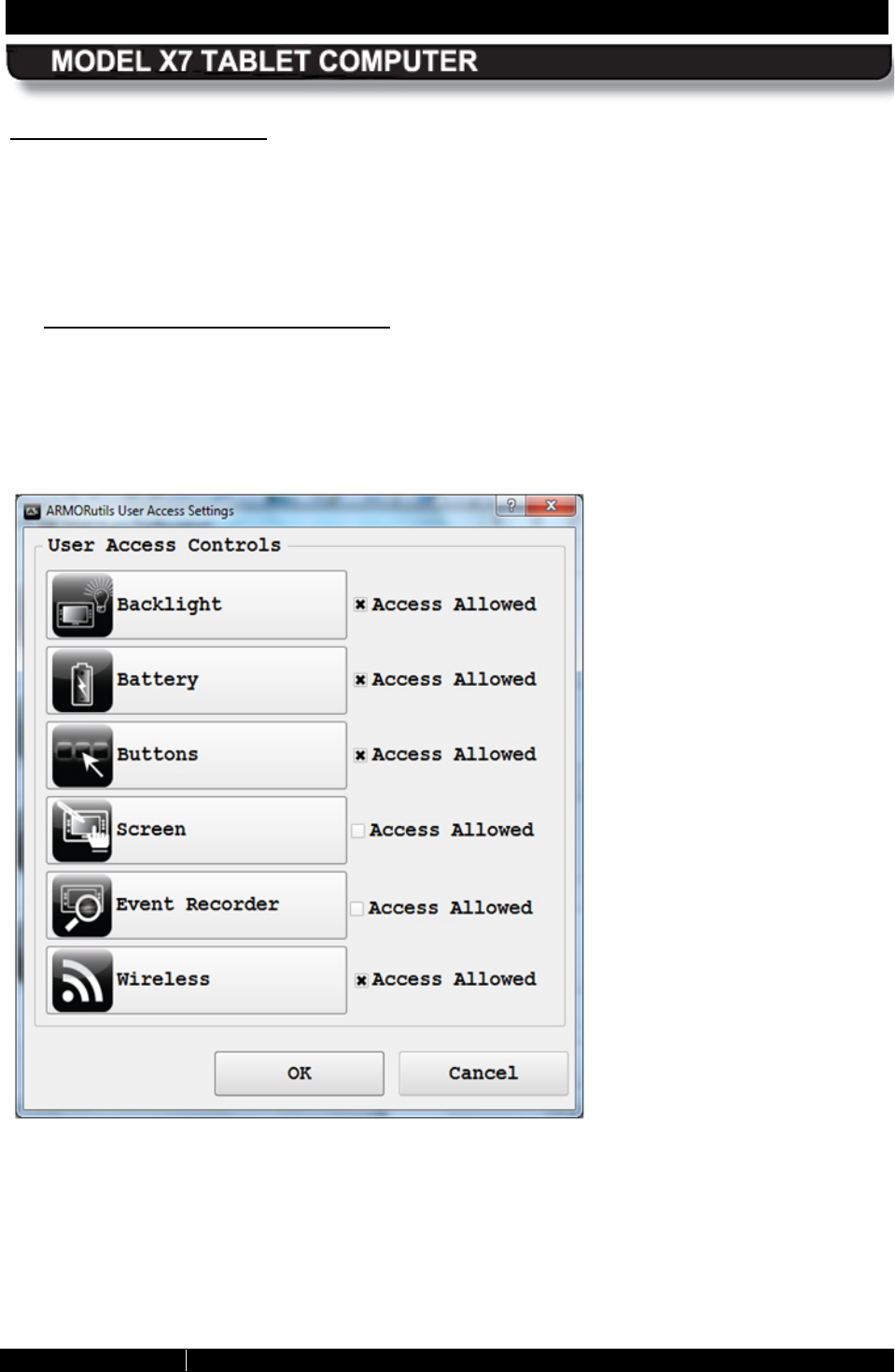
SECTION 5 YOUR ARMOR X7 SOFTWARE PAGE 114
9711-26400-0001
EXPORT CONTROLLED – SEE PAGE 3
Rev A
Administration B utton
The Administration button is normally hidden from view. To make this button available, press
and hold the Fn button on the right control panel and click on the Configuration option on the
ARMORutils Main window. The Configuration dialog window will re-open with the
Administration button visible. Click on the Administration button to open the User Access
Settings window shown in Figure 57.
User Access Settings Window
This window allows an administrator to deny access by users to a particular dialog window
or function. Uncheck the applicable box and click OK to disable user access. The disabled
dialog window button will appear grayed out in the user’s ARMORutils main window, as
illustrated in Figure 58. Here, the Screen Setup and Button Setup options are disabled.
Figure 57. User Access Settings Dialog
Disables access to the
Backlight Setup dialog.
Disables access to the
Charger Settings and
Conditioning Menu windows.
Disables access to the
Buttons Setup dialog.
Disables access to the
Screen Setup dialog.
Disables access to the
Event Recorder window in
the Diagnostics dialog.
Disables access to the
Wireless Setup dialog.
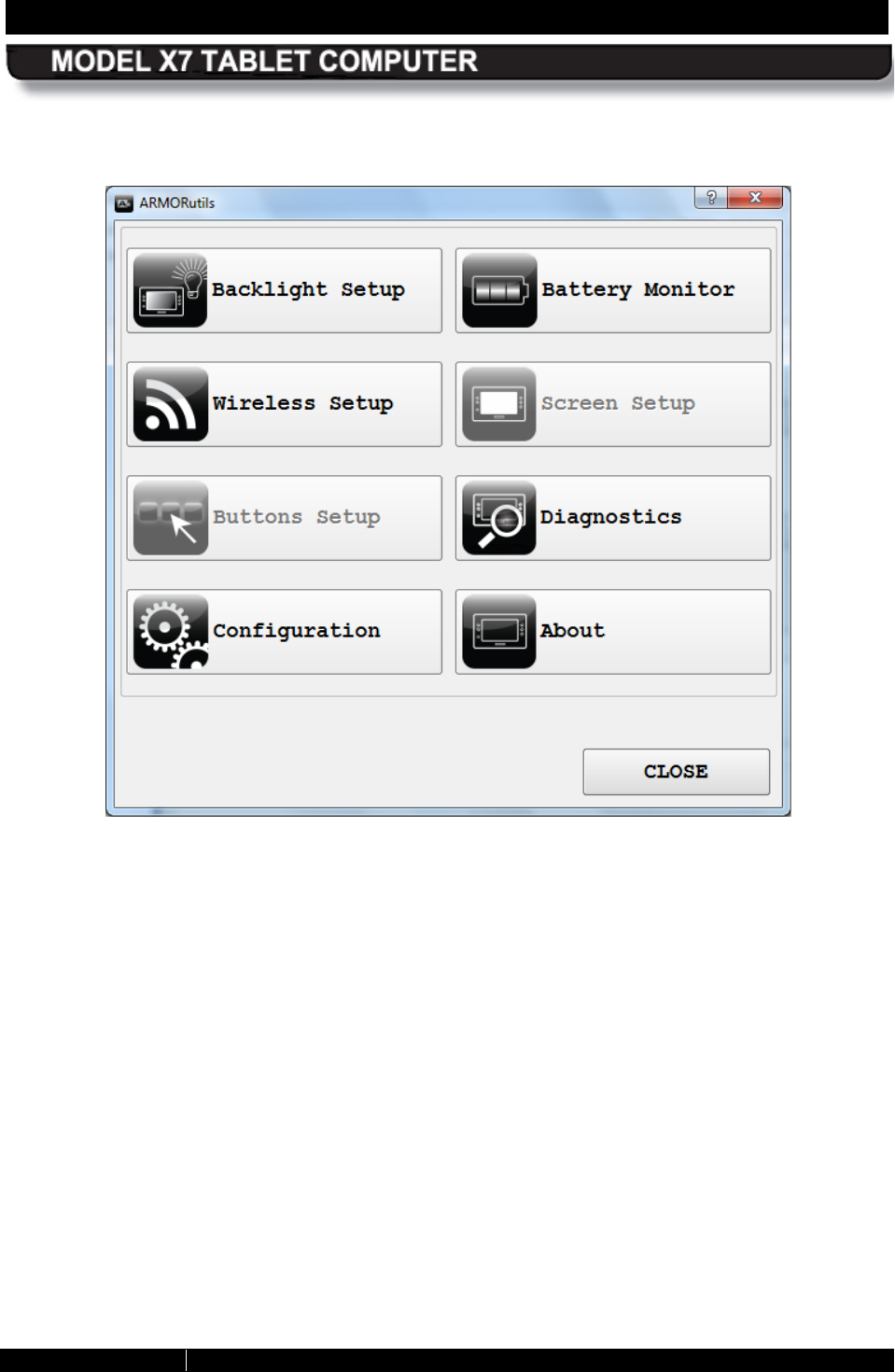
SECTION 5 YOUR ARMOR X7 SOFTWARE PAGE 115
9711-26400-0001
EXPORT CONTROLLED – SEE PAGE 3
Rev A
Figure 58. Example of the ARMORutils Main Screen with Options Disabled
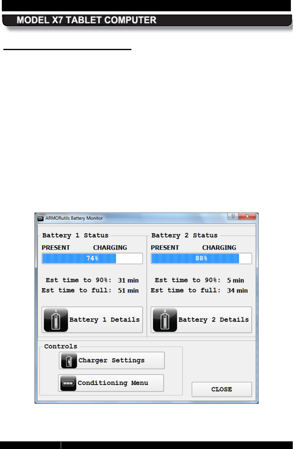
SECTION 5 YOUR ARMOR X7 SOFTWARE PAGE 116
9711-26400-0001
EXPORT CONTROLLED – SEE PAGE 3
Rev A
B attery Monitor Dialog
The Battery Monitor dialog window is shown in Figure 59. This window provides the following
information about each battery:
• Current charge level (% of the maximum energy capacity)
• Current status – whether the battery is CHARGING, DISCHARGING, FULLY
CHARGED, FULLY DISCHARGED, READY or NOT READY. A READY status indicates
a waiting state, such as the batteries are fully charged and waiting to discharge or a
second battery is waiting for the first battery to reach a particular charge level.
NOTE: If the status is NOT READY, the system cannot read the battery status and a
fault condition exists.
• Estimated time to 90% of full charge
• Estimated time to full charge if external power is connected or the estimated remaining
operating time if on batteries only.
There are also four buttons on this window that open additional dialogs or information windows:
Battery 1 Details, Battery 2 Details, Charger Settings and Conditioning Menu. The
functions of these buttons is described in the following paragraphs.
Figure 59. ARMORutils Battery Monitor Dialog
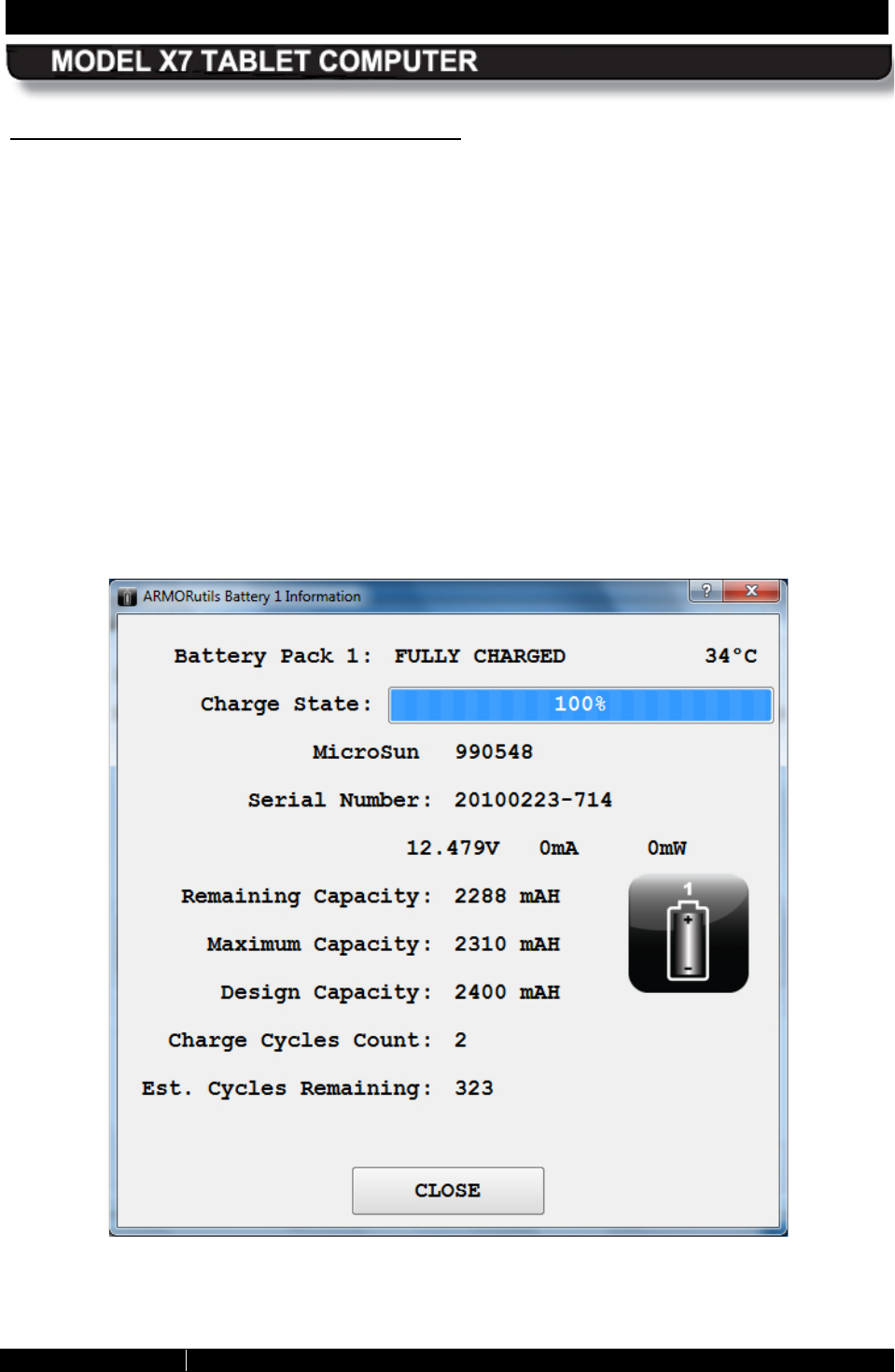
SECTION 5 YOUR ARMOR X7 SOFTWARE PAGE 117
9711-26400-0001
EXPORT CONTROLLED – SEE PAGE 3
Rev A
B attery 1 and B attery 2 Details B uttons
Select a Battery Details button to open a Battery Information window. Figure 60 shows a
typical window for the #1 battery. This window provides the same % charge and status
information as the Battery Monitor window but it also provides more detailed information about
the battery including:
• the battery’s serial number
• its current voltage, operating current and dissipated power in watts.
• the battery’s remaining energy capacity in mAh
• it’s maximum energy capacity in mAh
• the battery’s design energy capacity in mAh
• it’s accumulated cycle count
NOTE: A negative sign (-) appears next to a charge value in mAh when a battery is discharging.
The absence of a sign indicates the battery is charging or is fully charged.
Figure 60. ARMORutils Battery Information Window
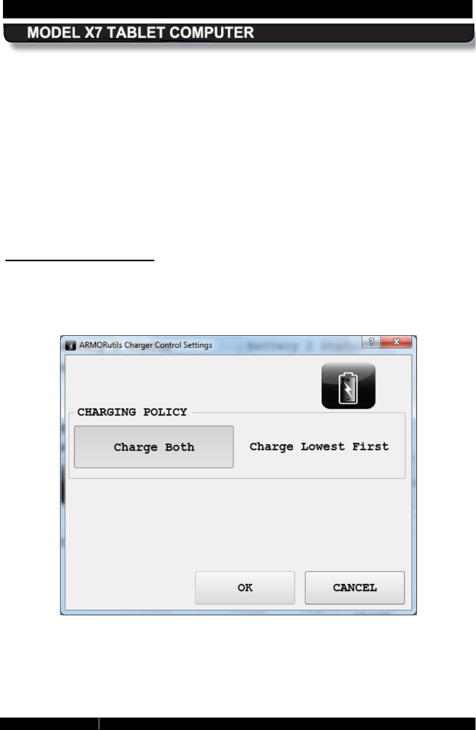
SECTION 5 YOUR ARMOR X7 SOFTWARE PAGE 118
9711-26400-0001
EXPORT CONTROLLED – SEE PAGE 3
Rev A
Remaining Capacity – This is the current energy level expressed in mAh instead of % of
charge.
Maximum Capacity – This is the current maximum energy capacity that the battery can
achieve. This value is determined primarily by the battery’s age, operating temperature history
and total number of accumulated charge cycles.
Design Capacity – This is the maximum capacity that the battery was designed to hold.
Charge Cycles Count – This is the total number of times the battery has been discharged
below the 30% level and then recharged.
Est. Cycles Remaining – This is a rough estimate of the number of remaining cycles before
your battery reaches it’s 80% capacity, at which point it is a candidate for replacement. This
estimate is based on an industry average of 400 cycles under nominal usage. When the
remaining cycles count reaches 0, you should consider replacing the battery.
Charger S ettings B utton
Click on the Charger Settings button to open the Charger Control Settings window shown in
Figure 61. In this window, you can decide what charging policy the system will use when two
batteries are installed.
Figure 61. ARMORutils Charger Control Settings Window
SECTION 5 YOUR ARMOR X7 SOFTWARE PAGE 119
9711-26400-0001
EXPORT CONTROLLED – SEE PAGE 3
Rev A
C harge B oth
If you select Charge Both, both batteries will charge at the same time regardless of individual
battery charge level. The total charge level indicated is determined by adding the charge of both
batteries and dividing this sum by 2.
Charge Lowes t First
If you choose Charge Lowest First, the battery with the lowest charge will be charged to 80%,
followed by the next lowest battery. Once both are at 80%, the first charged battery will be
charged to 100%, followed by the second charged battery.
Click on OK to save the new default setting. Select CANCEL to exit without changing the policy.
Conditioning Menu B utton
Click on the Conditioning Menu button to open the Battery Conditioning window shown in
Figure 62. This window will display the conditioning cycle information for each battery. It also
allows you to select a single battery to condition, or to select both batteries.
Your X7 batteries are self conditioning/calibrating and do not normally require conditioning.
NOTE
Conditioning, or calibration, should only be performed if you notice
that the levels reported by Windows or ARMORutils are
consistently different from actual battery performance, as this adds
to the total cycle count of the battery.
The conditioning process consists of first charging the battery to a full charge, then drawing the
charge down to its minimum, followed by charging the battery back to a full charge. NOTE: A
negative value may appear for the discharge cycle mAh reading; this is normal.
The entire conditioning process takes about 8 hours for two batteries.
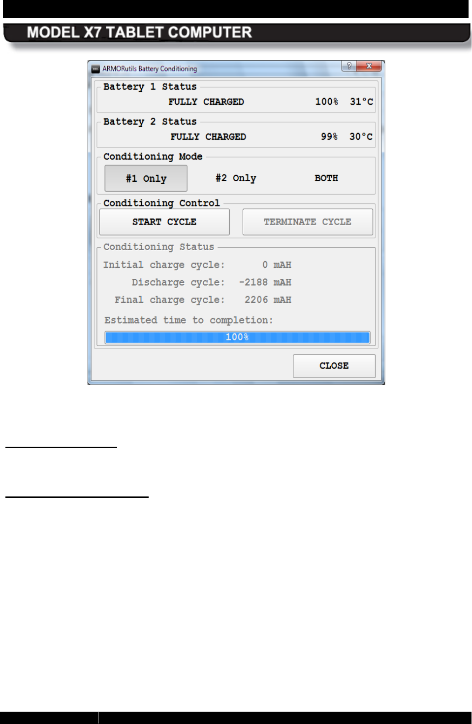
SECTION 5 YOUR ARMOR X7 SOFTWARE PAGE 120
9711-26400-0001
EXPORT CONTROLLED – SEE PAGE 3
Rev A
Figure 62. Battery Conditioning Window
S tart C yc le B utton
Click on the START CYCLE button to begin the conditioning process.
Terminate Cycle B utton
Click on the TERMINATE CYCLE button at any time to stop the conditioning process. NOTE: If
you terminate the conditioning process, you will have to start again from the beginning.
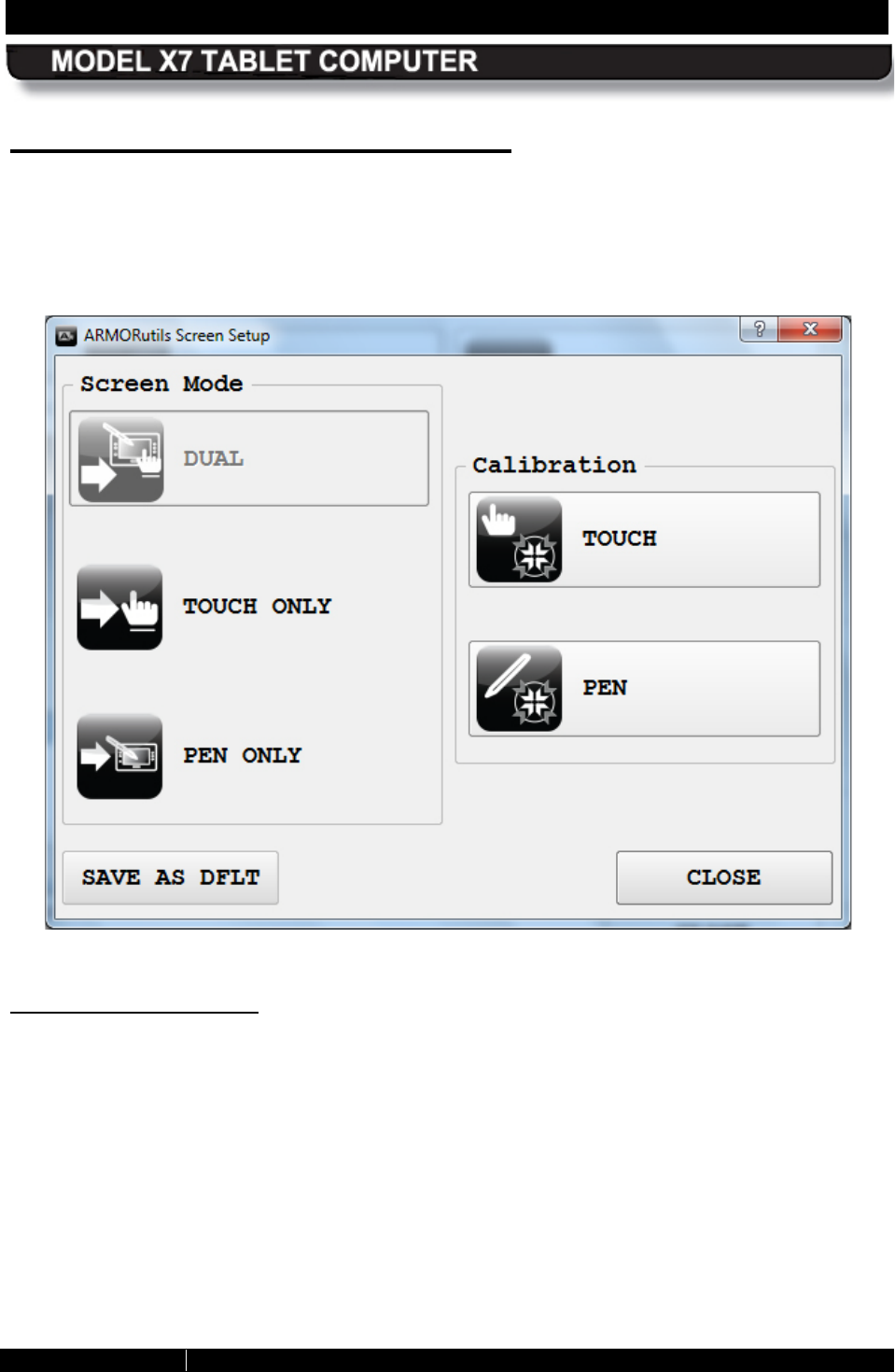
SECTION 5 YOUR ARMOR X7 SOFTWARE PAGE 121
9711-26400-0001
EXPORT CONTROLLED – SEE PAGE 3
Rev A
S creen S etup Dialog Window
The Screen Setup dialog (Figure 63) is used to select the current display mode and to access
calibration routines for both the touch and pen screens. There are three display modes: Dual,
Touch Only and Pen Only. The example below shows the system is in Dual Mode (Dual mode
option grayed out), which means both the Touch Only and Pen Only modes are available.
Figure 63. ARMORUtils Screen Setup Dialog
S creen Mode Options
These options allow you to select the current display mode. For example, click on the Touch
Only button to enable only the touch screen and disable the pen screen. Click OK to change to
the new mode. The Touch Only mode option will become grayed, as illustrated in Figure 64.
The Touch Only option is grayed out because it is the mode that is enabled and is not available
for selection. The Dual Mode and Pen Only options are contrasted, indicating that these two
modes are available.
Click on the Pen Only option to enable the pen screen and disable the touch screen, or click on
Dual Mode to enable both screens.
Click on SAVE AS DFLT to activate the new display mode. The button will change to a darker
color to indicate the change was saved.
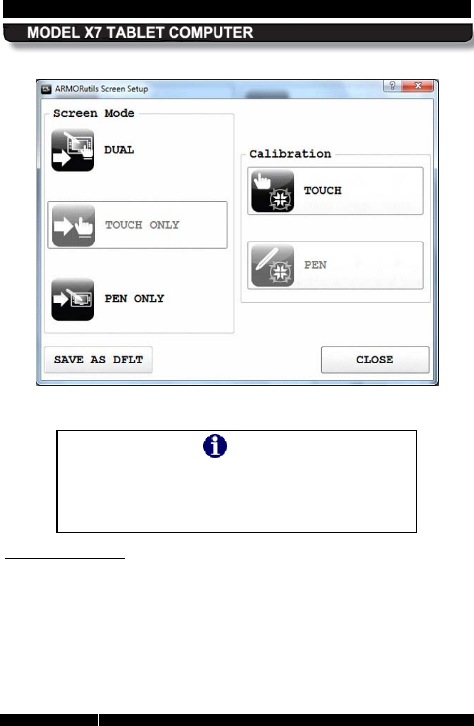
SECTION 5 YOUR ARMOR X7 SOFTWARE PAGE 122
9711-26400-0001
EXPORT CONTROLLED – SEE PAGE 3
Rev A
Figure 64. Screen Setup Dialog with Touch Screen Only Enabled
NOTE
You can also find options to change the display mode through pen
and touch utilities in Windows Control Panel. However, you should
only use ARMORutils to change the display mode since
ARMORutils will override any screen mode options selected in the
Windows utilities.
Calibration Options
To calibrate a screen, click on TOUCH or PEN option in the Calibration panel. Follow the on-
screen instructions. If one of the screen calibration options is grayed out, it is not available with
the current mode setting.
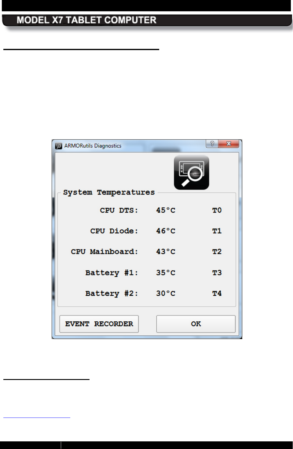
SECTION 5 YOUR ARMOR X7 SOFTWARE PAGE 123
9711-26400-0001
EXPORT CONTROLLED – SEE PAGE 3
Rev A
Diagnostics Dialog Window
The Diagnostics window displays the following internal temperatures of the X7 tablet, as shown
in the example in Figure 65:
• CPU core temperature (DTS and Diode)
• CPU Mainboard temperature
• Battery #1 temperature
• Battery #2 temperature
This temperature information can be used by DRS to diagnose possible system problems.
Figure 65. ARMORutils Diagnostics Dialog
E vent Recorder B utton
Click on the Event Recorder button to open the Event Recorder window shown in Figure 66.
This window provides entry fields and options to create a log file of temperature variations and
battery status over time. For instructions on how to use the Event Recorder function, refer to
Creating an Event Log.
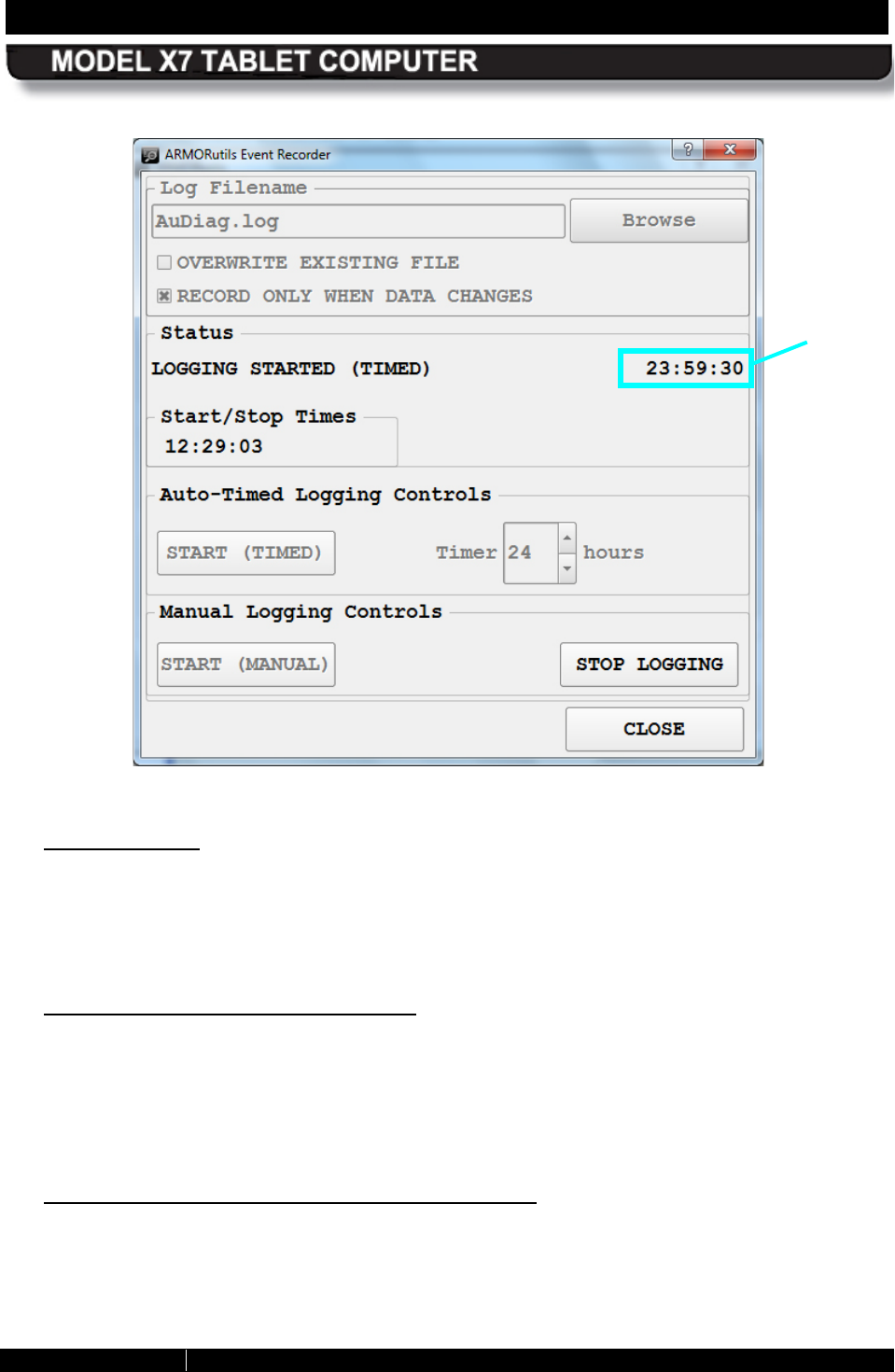
SECTION 5 YOUR ARMOR X7 SOFTWARE PAGE 124
9711-26400-0001
EXPORT CONTROLLED – SEE PAGE 3
Rev A
Figure 66. ARMORUtils Event Recorder Window
Log Filename
The filename that appears in the Log Filename field when you first open the Event Recorder
window is the default log file in the ARMORutils application folder. You can use this default log
filename or enter a new filename. You can also click on the BROWSE button to select from
other stored files or create a different folder to store your files.
“Overwrite E xis ting File” Option
If you start a new logging session, the data will be appended to the existing file shown in the
Log Filename field by default. If you want to save your logging as a different file, enter the new
filename. If you want your new log file to overwrite a displayed filename, check the Overwrite
Existing File option. You can browse to select a file already created or you can create a new
file and/or folder.
“R ecord Only When Data Changes ” Option
The Event Recorder program normally logs a line of data ever 6 seconds. This can result in a
very large file if the logging runs for long periods of time. The file size can be reduced
considerably by checking the Record only when data changes option. With this option
selected, the recorder will only enter a line of data when any data point changes.
TIME
REMAINING
APPEARS
HERE
SECTION 5 YOUR ARMOR X7 SOFTWARE PAGE 125
9711-26400-0001
EXPORT CONTROLLED – SEE PAGE 3
Rev A
Your Event Recorder is pre-configured from the factory with this option checked. Uncheck it if
you want to record data continuously.
S tatus
The Status panel displays the time the logging was started, the time remaining (if Auto Logging
is used) and the time logging was stopped (either at the end of an auto-timed period or when
the STOP LOGGING button was selected).
Timer
Here you can set the duration of your logging session by typing in the number of hours directly
or by using the up/down arrows. The current maximum auto-timed logging duration is 168 hours
(1 week).
S tart Timed B utton
Click on this button to start the timed logging period.
S tart Manual B utton
Click on this button to manually start the logging process. The logging process will continue until
you select the STOP LOGGING button or the computer is turned off.
S top L ogging B utton
Click on this button to stop logging either in auto-timed or manual mode. NOTE: In manual
mode, the logging will continue until you stop it or turn power off to the computer.
Close B utton
Click on this button to close the Event Recorder window. Your logging session will continue in
the background.
Us ing the Event Log File
In addition to temperature change, the event log also records other key information about the
batteries, such as their manufacturer, model number, serial numbers and a history of their
charging and discharging during the logging period. A sample event log printout is shown in
Figure 67. The battery status codes and column headings are defined in the header.
You can open and view the log file in any text application. The file can be printed out or
exported to a database program like Microsoft Excel or Access and converted to a graph or
chart.
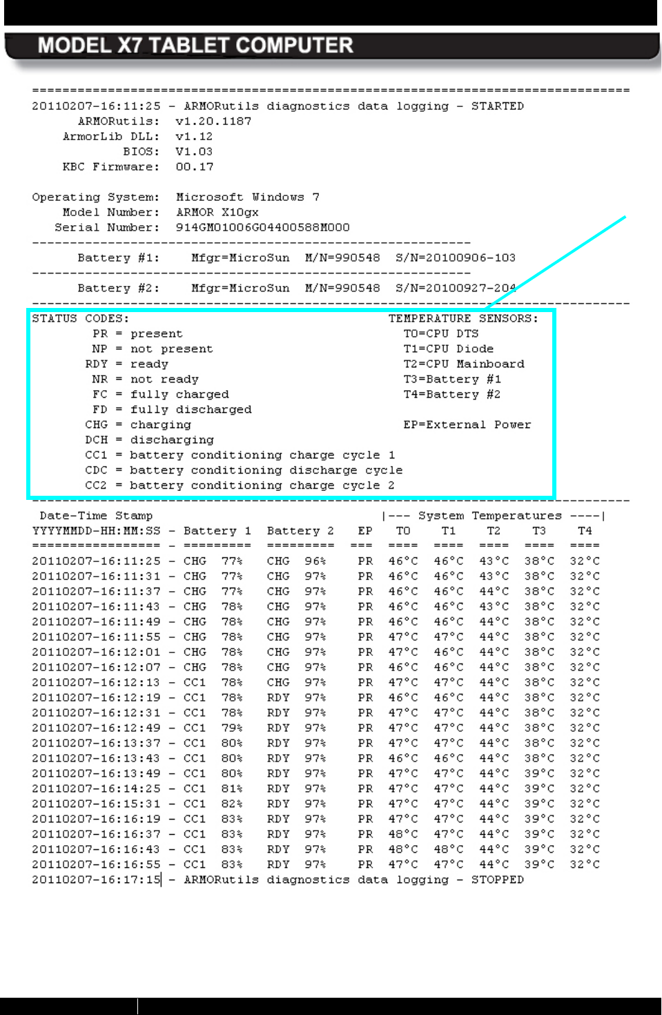
SECTION 5 YOUR ARMOR X7 SOFTWARE PAGE 126
9711-26400-0001
EXPORT CONTROLLED – SEE PAGE 3
Rev A
Figure 67. Sample Event Log File
DEFINITIONS
SECTION 5 YOUR ARMOR X7 SOFTWARE PAGE 127
9711-26400-0001
EXPORT CONTROLLED – SEE PAGE 3
Rev A
AR MOR utils About Window
The About window (Figure 68) displays the current version and release date of the ARMORutils
software. It also provides a contact telephone number for the DRS Tactical Systems Technical
Support call center and the internet address to the ARMOR website where you can log on to
access support information.
Figure 68. ARMORutils About Window
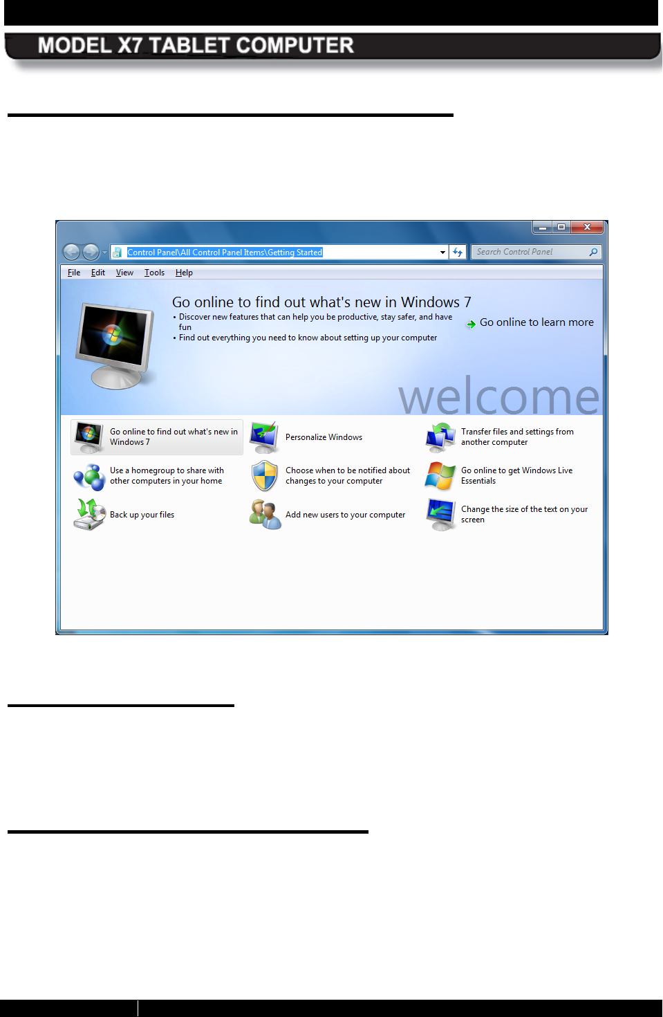
SECTION 5 YOUR ARMOR X7 SOFTWARE PAGE 128
9711-26400-0001
EXPORT CONTROLLED – SEE PAGE 3
Rev A
G etting S tarted with Windows 7
Click on Start à Getting Started to open the Windows welcome page (Figure 69) and access
a number of helpful links and resources. NOTE: Screen content and layout may vary depending
on your version of Windows 7 and any added service packs or updates.
Figure 69. Windows 7 Welcome Page
Help for Windows
For information on using Microsoft Window’s features, options, applications and utilities, refer to
the Microsoft help files and tutorials by clicking on the Start button and selecting Help and
Support.
Windows Dis play Utilities
The following paragraphs provide a brief description of key Windows display utilities to help you
configure and begin using your X7. A detailed description of all of the functions and capabilities
of these and other Windows utilities is beyond the scope of this manual. Refer to the Windows
Help Resources for in-depth descriptions and tutorials.
NOTE: Windows utilities and the way you get to them may vary depending on the version of
your Windows operating system.
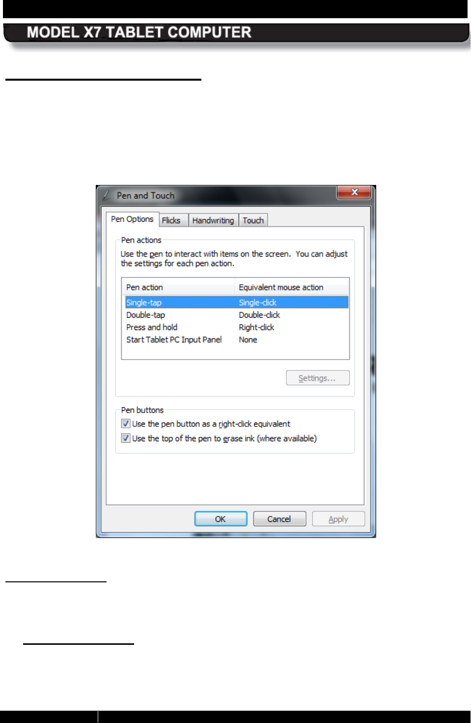
SECTION 5 YOUR ARMOR X7 SOFTWARE PAGE 129
9711-26400-0001
EXPORT CONTROLLED – SEE PAGE 3
Rev A
Pen and Touch Utility
The Pen and Touch utility is a Windows program that provides settings that effect how the
active pen works with the pen screen and how a fingertip or passive stylus works with the touch
screen.
To open this utility, select Start à Control Panel à Hardware and Sound à Pen and Touch.
The Pen and Touch utility opens, as shown in Figure 70.
Figure 70. Pen and Touch Utility – Pen Options Tab
Pen Options Tab
The Pen Options tab opens by default and provides settings that are applicable to the pen
screen only.
Pen Actions Panel
Highlight an action from the Pen Actions list and click on the Settings button (if active) to
open a settings window, then select options or make adjustments.
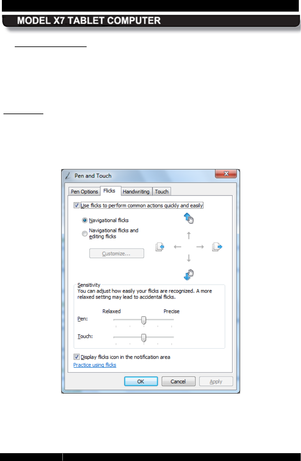
SECTION 5 YOUR ARMOR X7 SOFTWARE PAGE 130
9711-26400-0001
EXPORT CONTROLLED – SEE PAGE 3
Rev A
Pen B uttons Panel
Use the Pen button as a right-click equivalent option – This option is overridden by the
pen button options in the Pen tab of the Pen Tablet Properties utility, regardless of whether
it is checked or not.
Use the top of the pen to erase ink option – The erase function is not supported in the X7
from any utility option.
Flicks Tab
The Flicks tab provides settings that are applicable to both the pen and touch screens. Flicks
are short quick gestures either up, down, left or right that produce common actions such as
scrolling through a document, dragging an object, or opening a folder. Click on the Practice
using flicks link at the bottom of the window to access a tutorial.
Figure 71. Pen and Touch Utility – Flicks Tab