DRS Tactical Systems 622ANH Intel Centrino Advanced-N 6200 User Manual 2 of 2
DRS Tactical Systems, Inc. Intel Centrino Advanced-N 6200 Users Manual 2 of 2
Contents
- 1. Manual
- 2. Users Manual 1 of 2
- 3. Users Manual 2 of 2
Users Manual 2 of 2
SECTION 5 YOUR ARMOR X7 SOFTWARE PAGE 131
9711-26400-0001
EXPORT CONTROLLED – SEE PAGE 3
Rev A
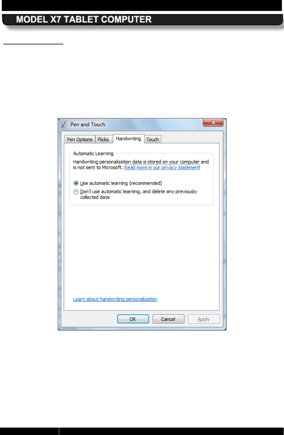
Handwriting Tab
The Handwriting tab provides settings that are applicable to both the pen and touch screens.
The options on this tab allow you to enable or disable the automatic handwriting learning
feature. Click on the “Learn about handwriting personalization link at the bottom of the window
for information about automatic learning and how to train your tablet to recognize your personal
handwriting style.
Figure 72. Pen and Touch Utility – Handwriting Tab
SECTION 5 YOUR ARMOR X7 SOFTWARE PAGE 132
9711-26400-0001
EXPORT CONTROLLED – SEE PAGE 3
Rev A
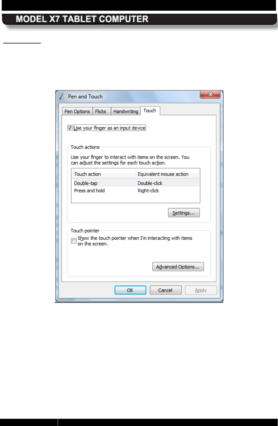
Touch Tab
The Touch tab provides settings that are applicable to the touch screen only. The options on
this tab affect how the pen, or your finger, interacts with the touch screen.
Check the “Use your finger as an input device” option to use either the pen or your finger
with the touch screen.
Figure 73. Pen and Touch Utility – Touch Tab
SECTION 5 YOUR ARMOR X7 SOFTWARE PAGE 133
9711-26400-0001
EXPORT CONTROLLED – SEE PAGE 3
Rev A
Touch Actions
Highlight a touch action and click on the Settings button to open an adjustment window.
Touch P ointer
Select this option to place a pointer at the touch point. A virtual mouse image will also
appear next to the pointer, as shown in Figure 74 . You can then click on the left or right
mouse button to produce the appropriate mouse action.
Click on the Advanced Options button to open a window where you can adjust the touch
pointer position, appearance and behavior.
Figure 74. Touch Tab Virtual Mouse Pointer
SECTION 5 YOUR ARMOR X7 SOFTWARE PAGE 134
9711-26400-0001
EXPORT CONTROLLED – SEE PAGE 3
Rev A
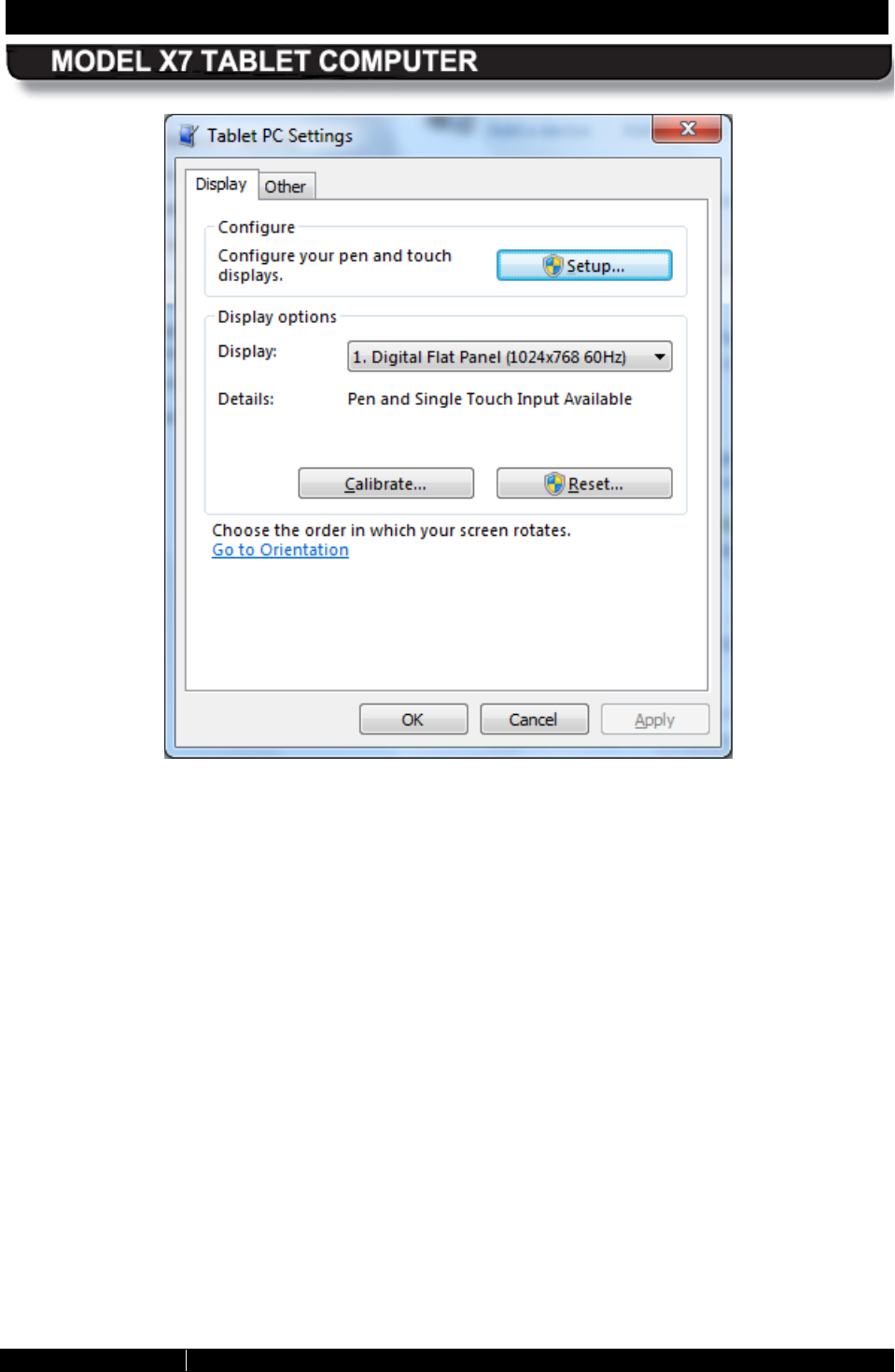
Tablet P C S ettings Utility
To open this utility, select Start à Control Panel à Hardware and Sound à Tablet PC
Settings. The Tablet PC Settings utility opens, as shown in Figure 75.
Dis play Tab
The Display tab provides links to initiate screen calibration. Other display options are not used.
Configure your pen and touch displays
This option is not supported by the X7. Use the Screen Setup dialog in ARMORutils to
change display modes.
Dis play Options
This option is not supported by the X7. Select Control Panel à Hardware and Sound à
Display à Change Display settings to change settings for multiple displays.
C alibrate B utton
Click on the Calibrate button and select Pen input or Touch input to calibrate a screen.
R eset B utton
Click on this button if you want to remove the calibration you just performed.
G o to Orientation
This option is not supported by the X7.
SECTION 5 YOUR ARMOR X7 SOFTWARE PAGE 135
9711-26400-0001
EXPORT CONTROLLED – SEE PAGE 3
Rev A
Figure 75. Tablet PC Settings – Display Tab
SECTION 5 YOUR ARMOR X7 SOFTWARE PAGE 136
9711-26400-0001
EXPORT CONTROLLED – SEE PAGE 3
Rev A
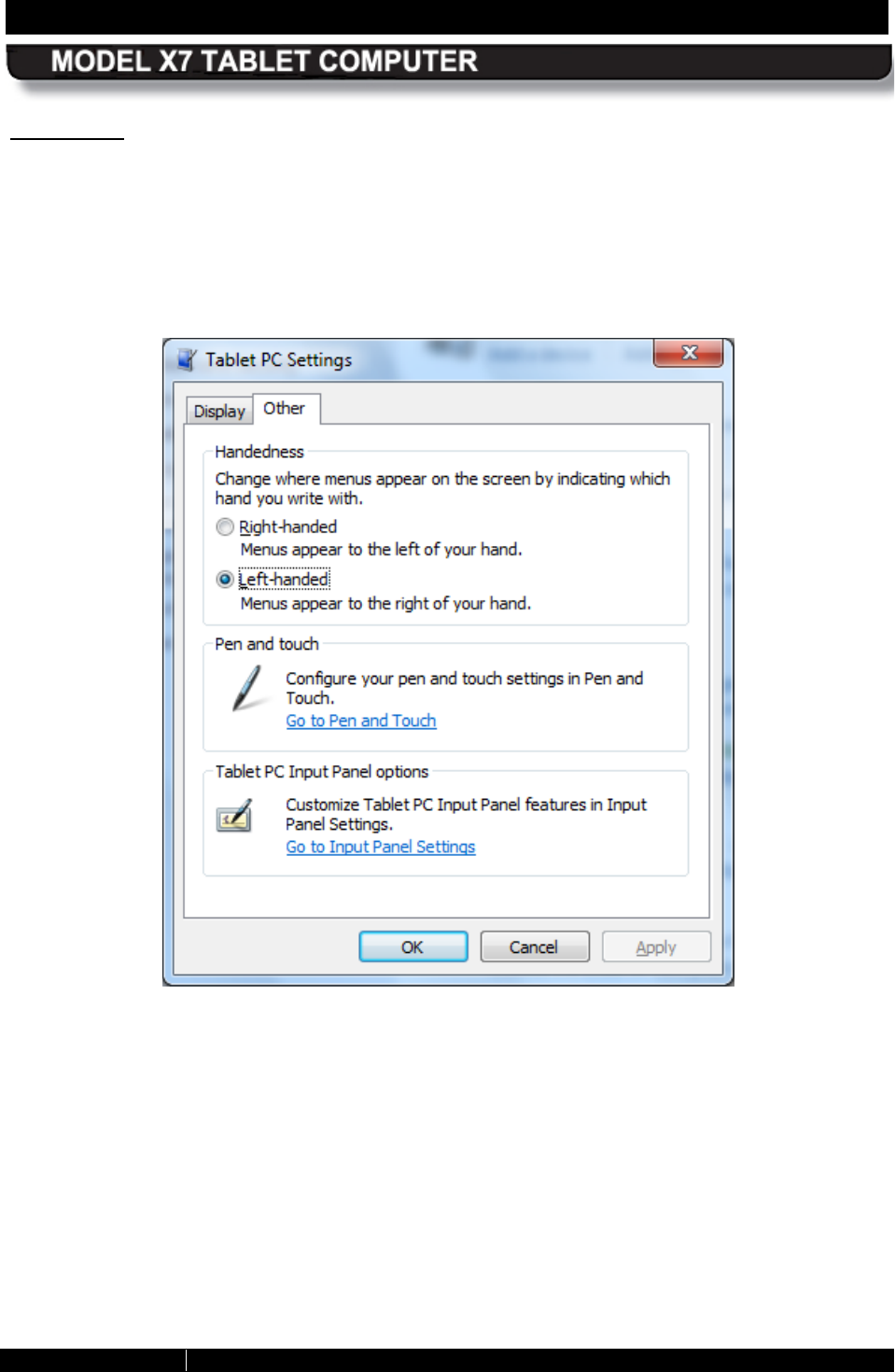
Other T ab
The Other tab (Figure 76) allows you to change where an on-screen menu appears when you
activate the pen or touch display so that your hand does not block your view of the menu. For
example, if you are left-handed, check the Left-handed option to have the menus appear to the
right of the pointer.
It also provides a link to configure settings for the Input Panel.
Figure 76. Tablet PC Settings Utility – Other Tab
SECTION 5 YOUR ARMOR X7 SOFTWARE PAGE 137
9711-26400-0001
EXPORT CONTROLLED – SEE PAGE 3
Rev A
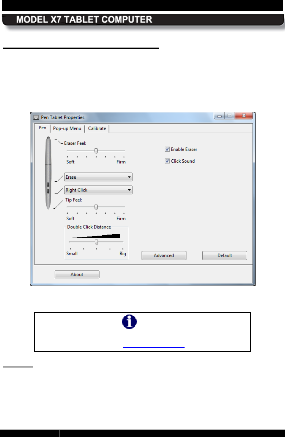
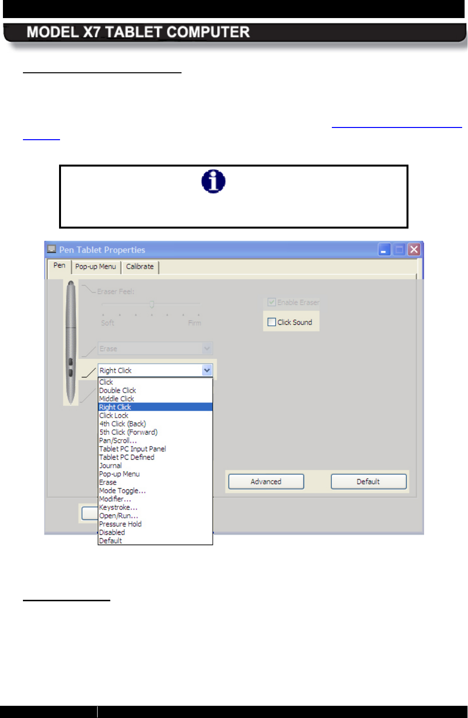
Pen Tablet P roperties Utility
The following paragraphs briefly describe the purpose and actions of the Pen Tablet Properties
utility (the name may be different depending on which version of Windows 7 you have). To open
the utility window, select Start à Control Panel à Hardware and Sound and click on the Pen
Tablet Properties icon to open the Pen Tablet Properties window shown in Figure 77.
Figure 77. WACOM Pen Tablet Properties Window – Pen Tab
NOTE
The pen that comes with your ARMOR X7 has only one side button
and no eraser function (see Your X7 Active Pen).
Pen Tab
The Pen tab is displayed by default when the Pen Tablet Properties window opens. The pen
pictured in the tab is a WACOM™ pen that is normally used in advanced drawing tablets. Its
functionality far exceeds what is required for your X7 tablet. Consequently, we have provided a
simpler active pen.
SECTION 5 YOUR ARMOR X7 SOFTWARE PAGE 138
9711-26400-0001
EXPORT CONTROLLED – SEE PAGE 3
Rev A
S upported Options
Figure 78 and Figure 79 highlight those functions and options that are supported by your
ARMOR X7 active pen.
NOTE
Options not supported by the X7 pen are grayed out in Figure 78
and Figure 79
for illustration purposes only. They are not grayed
out on the actual application screen image.
Figure 78. Settings and Options Supported by the ARMOR X7 Active Pen
Click S ound
Check the Click Sound option to enable a clicking sound when you perform an action with
the pen.
E ras er
The X10gx does not support the Erase function.
SECTION 5 YOUR ARMOR X7 SOFTWARE PAGE 139
9711-26400-0001
EXPORT CONTROLLED – SEE PAGE 3
Rev A
S ide Button Menu Options
The side button can be set to perform different functions that are selected from the pull
down menu shown in Figure 79. The default function is “Right Click”.
Only the lower button menu is used with the X7 pen. Refer to Explanation of Side Button
Options in the Appendix for a description of each menu option.
NOTE
Some side switch settings may work differently in different
software applications.
Figure 79. Side Button Menu Options
Default B utton
Click on the Default button to return the side button setting to Right Click.
SECTION 5 YOUR ARMOR X7 SOFTWARE PAGE 140
9711-26400-0001
EXPORT CONTROLLED – SEE PAGE 3
Rev A
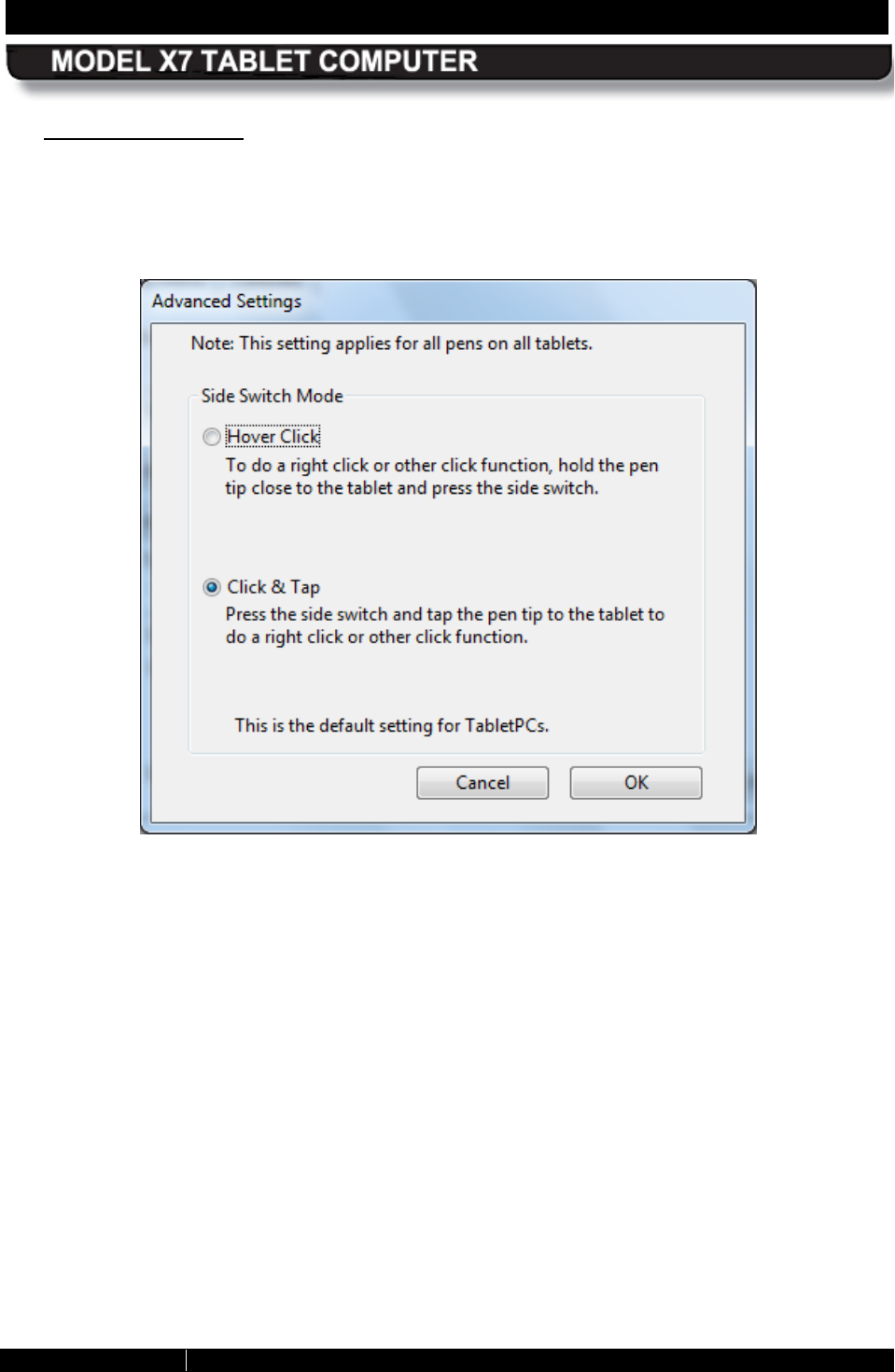
Advanced Button
Click on the Advanced button to open the Advanced Settings window, as shown in Figure
80. The two options in this window allow you to set the way the side switch will be used to
perform a right click action. Click & Tap is the default action.
Figure 80. Pen Tablet Properties - Advanced Settings Window
SECTION 5 YOUR ARMOR X7 SOFTWARE PAGE 141
9711-26400-0001
EXPORT CONTROLLED – SEE PAGE 3
Rev A
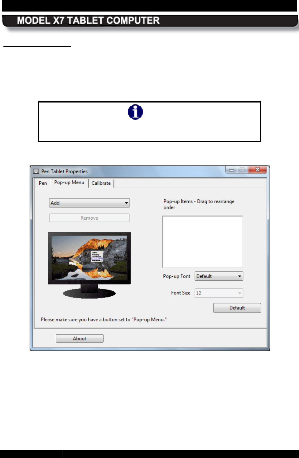
Pop-up Menu Tab
The Pop-up Menu tab is shown in Figure 81. This tab allows you to add additional functionality
to the side button. These functions will be displayed in a pop-up menu when the side button is
pressed while in an application or working on the desktop. If only one function has been
selected, only that function will be available.
NOTE
To use the functions set in the pop-up menu, you must select the
“Pop-up Menu” option from the side button menu in the Pen tab.
Figure 81. Pen Tablet Properties – Pop-up Menu Tab
SECTION 5 YOUR ARMOR X7 SOFTWARE PAGE 142
9711-26400-0001
EXPORT CONTROLLED – SEE PAGE 3
Rev A
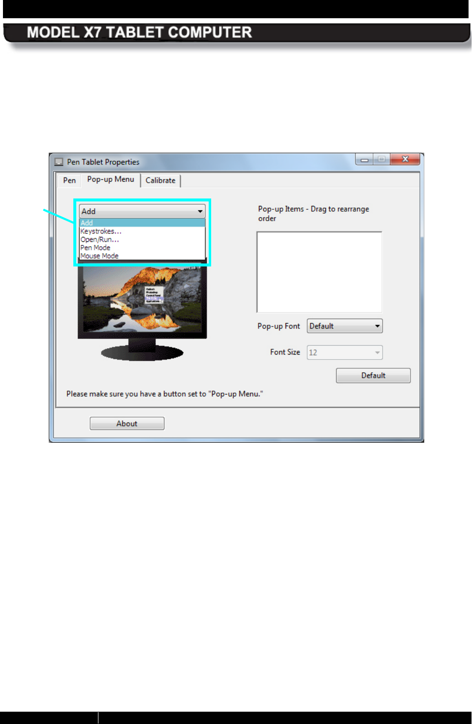
Click on the down arrow in the Add field to open a list of available functions then select and
configure the desired function. Those functions that are selected will appear in the Pop-up
Items panel to the right of the Add field. Click on the Remove button to delete a function.
When you are using the pen in an application or on the desktop and you press the side button, a
small menu is displayed with the options you have configured.
Figure 82. Pop-up Menu Add Options
OPTIONS
MENU
SECTION 5 YOUR ARMOR X7 SOFTWARE PAGE 143
9711-26400-0001
EXPORT CONTROLLED – SEE PAGE 3
Rev A
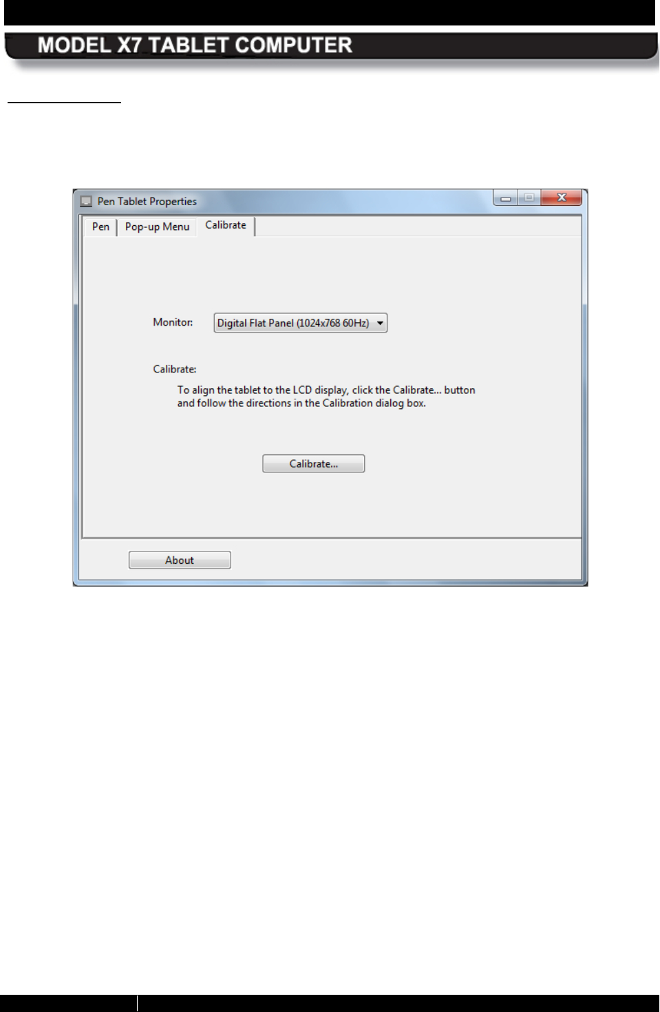
Calibrate Tab
The Calibrate tab is shown in Figure 83. Click on the Calibrate button to access the screen
calibration routine. Follow the on-screen instructions.
Figure 83. Pen Tablet Properties Window – Calibrate Tab
SECTION 5 YOUR ARMOR X7 SOFTWARE PAGE 144
9711-26400-0001
EXPORT CONTROLLED – SEE PAGE 3
Rev A
TrueS uite™ Fingerprint R ecognition S oftware
Your X7 comes pre-loaded with the AuthenTec® TrueSuite™ Premium fingerprint recognition
software. This application enables you to secure your computer login, access to specific folders
or loaded applications, and your logins to remote websites so that only you can access them
with a swipe of your finger or thumb.
Open the application by selecting Start à All Programs and open the TrueSuite folder in the
programs list (you may have to scroll down to see it). There are three options in this folder:
TrueSuite, TrueSuite Tray, and Uninstall TrueSuite. Click on the TrueSuite option to open
the TrueSuite window, as shown in Figure 84. You can also click on the TrueSuite Tray option
to place a TrueSuite icon in the systray where it will remain during your current session.
Mousing over this icon will open a menu where you can start the TrueSuite application. You can
also change the touch controls and access help options without opening the TrueSuite
application.
The application window opens with the My Settings panel displayed. There are four other panel
options available: Website Log On, File and Folder Lock, QuickLaunch, and Enrollment.
Click on the navigation icon in the upper right corner of any of these options to open the
panel.
Figure 84. AutenTec TrueSuite Application Window
Us ing the TrueS uite Application
You must install the TrueSuite application in order to initially register your finger and/or thumb
print. Refer to Using the Fingerprint Sensor for installation and setup instructions.
SECTION 5 YOUR ARMOR X7 SOFTWARE PAGE 145
9711-26400-0001
EXPORT CONTROLLED – SEE PAGE 3
Rev A
R ealtek® HD Audio Manager Application
This application allows you to configure your speakers, adjust headset audio and microphone
levels and create sound effects. Refer to Configuring your Audio System for instructions.
Figure 85. Realtek HD Audio Manager Application
SECTION 5 YOUR ARMOR X7 SOFTWARE PAGE 146
9711-26400-0001
EXPORT CONTROLLED – SEE PAGE 3
Rev A
Picasa 3® Image Capture
Picasa 3 is an image capture program that allows you to use the webcam for taking still pictures
and movies and for capturing barcodes. Refer to Capturing Images and Video for instructions on
how to use this application.
Figure 86. Picasa 3 Image Capture Application
SECTION 5 YOUR ARMOR X7 SOFTWARE PAGE 147
9711-26400-0001
EXPORT CONTROLLED – SEE PAGE 3
Rev A
Virtual Magnifying Glas s ™
This handy utility allows you to magnify portions of the screen that are too small to see clearly. It
projects a virtual magnifying glass over a portion of the screen, as shown in Figure 87. Refer to
Using the Screen Magnifier for instructions on how activate and use this application.
Figure 87. Virtual Magnifying Glass Application
SECTION 6 TROUBLESHOOTING PAGE 149
9711-26400-0001
EXPORT CONTROLLED – SEE PAGE 3
Rev A
Table of Contents List of Figures List of Tables Acronyms Glossary
6. TROUBLESHOOTING
This section addresses only those problems that can be corrected by replacing a removable
component such as a battery or digital card, by replacing or reseating an external cable, or by
changing a configuration setting. For any other failure, the tablet will have to be returned to DRS
Tactical Systems.
For each problem that occurs with your ARMOR X7 computer, there are specific steps that will
help isolate the problem to a failed component or to a configuration option that may be set
incorrectly. In many cases, a single action step will isolate or correct the problem. In others, a
troubleshooting flowchart with multiple actions may be needed.
Is olating the Problem
Table 21 lists possible problem areas with likely symptoms and then provides actions to correct
the problem. Use the Problem Area and Symptom columns to identify the problem you are
having, then follow any directions in the Action column or go to the indicated Flow Chart to
further isolate the problem.
Table 21. ARMOR X7 Trouble Symptoms
PROBLEM AREA SYMPTOM ACTION FLOW
CHART
Display (touch or pen
screen) Tapping with the pen
or
stylus does not
select or activate an
option, or the cursor
(pointer)
does not
align with the
fingertip or pen point.
1. Follow the instructions in
Calibrating the Display to
calibrate the screen.
Repeat up to 5 times if
necessary.
2.
If screen still does not
respond
correctly, send
tablet in for repair.
Display
Backlight goes on
and off. 1. Default the BIOS.
2. If not fixed, flash H8.
3. If not fixed, send tablet in
for repair.
SECTION 6 TROUBLESHOOTING PAGE 150
9711-26400-0001
EXPORT CONTROLLED – SEE PAGE 3
Rev A
PROBLEM AREA SYMPTOM ACTION FLOW
CHART
Display Pen does not right-
click
when held
against the screen.
1. Select Start
à
Control
Panel
à
Hardware and
Sound
à
Pen and Touch.
2. Highlight the
Press and
hold
option in the Pen
Actions panel and click on
Settings.
3. Ensure the
Enable press
and hold for right
clicking option is checked.
4. If problem is
not fixed,
replace pen.
Display
Pen does not right
click when side
button is pressed
(default setting).
1. Select Start
à
Control
Panel
à
Hardware and
Sound
à
Pen Tablet
Properties.
2.
Verify/change setting to
Right Click in bottom side
button menu.
Display
Pen not working in
center of display. Send tablet in for repair.
Display
Pen opens and
closes folders and
programs without
touching screen.
Send tablet in for repair.
Battery
Tablet will not
recognize a battery. TS-04
Battery Battery will not hold
a charge. Perform the procedure in What
to Do for an Overly-
Discharged Battery.
Battery
Battery consistently
shows a full charge
but does not meet
typical operating
times.
Perform the procedure in
Battery Conditioning.
NOTE:
If the battery still
shows poor performance,
replace it.
SECTION 6 TROUBLESHOOTING PAGE 151
9711-26400-0001
EXPORT CONTROLLED – SEE PAGE 3
Rev A
PROBLEM AREA SYMPTOM ACTION FLOW
CHART
Power System or
Battery
Charging/Fault LED
(indicator panel) is
on steady red.
The red LED will turn off when
the fault condition is removed.
Try removing external power
(if connected).
If the fault occurs on batteries
only, connect external power
and remove each battery one
at a time.
If the fault persists, return the
tablet for repair.
Power
System or
Battery Tablet will not power
up. TS-01
Run Tablet is locked up. TS-05
Run Screen rolls, flashes,
and then tablet
freezes up.
1. Remove both batteries and
connect AC adapter.
2. Reboot the tablet.
3.
If tablet works normally,
reinstall one battery at a
time and reboot until
problem reoccurs.
4.
Replace one or both
batteries as applicable.
Run
Tablet shuts down
on its own. 1. Start
à
Control Panel
à
Power Options and check
if the computer has a shut
down
setting to save
power.
2.
If no shut down option is
enabled, return tablet for
repair.
Boot Up
Tablet will not start
boot process. Power
ok.
TS-02
Boot Up
Tablet will not boot
into Windows. TS-03
Wireless Cannot connect to a
wireless network. TS-06
SECTION 6 TROUBLESHOOTING PAGE 153
9711-26400-0001
EXPORT CONTROLLED – SEE PAGE 3
Rev A
Troubleshooting Flowcharts
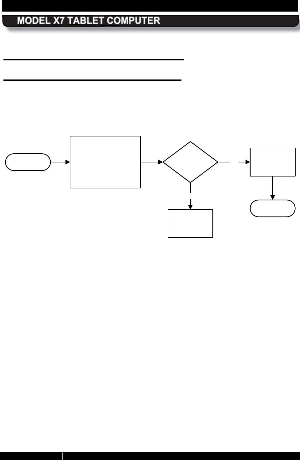
TS-01 Tablet will not power up
Start
1. Remove both
batteries and connect
tablet to docking
station or connect AC
adapter.
2. Attempt to power up.
Does tablet
power up?
Yes
Exit
Recharge or
replace
batteries.
No
Send tablet in
for repair.
SECTION 6 TROUBLESHOOTING PAGE 154
9711-26400-0001
EXPORT CONTROLLED – SEE PAGE 3
Rev A
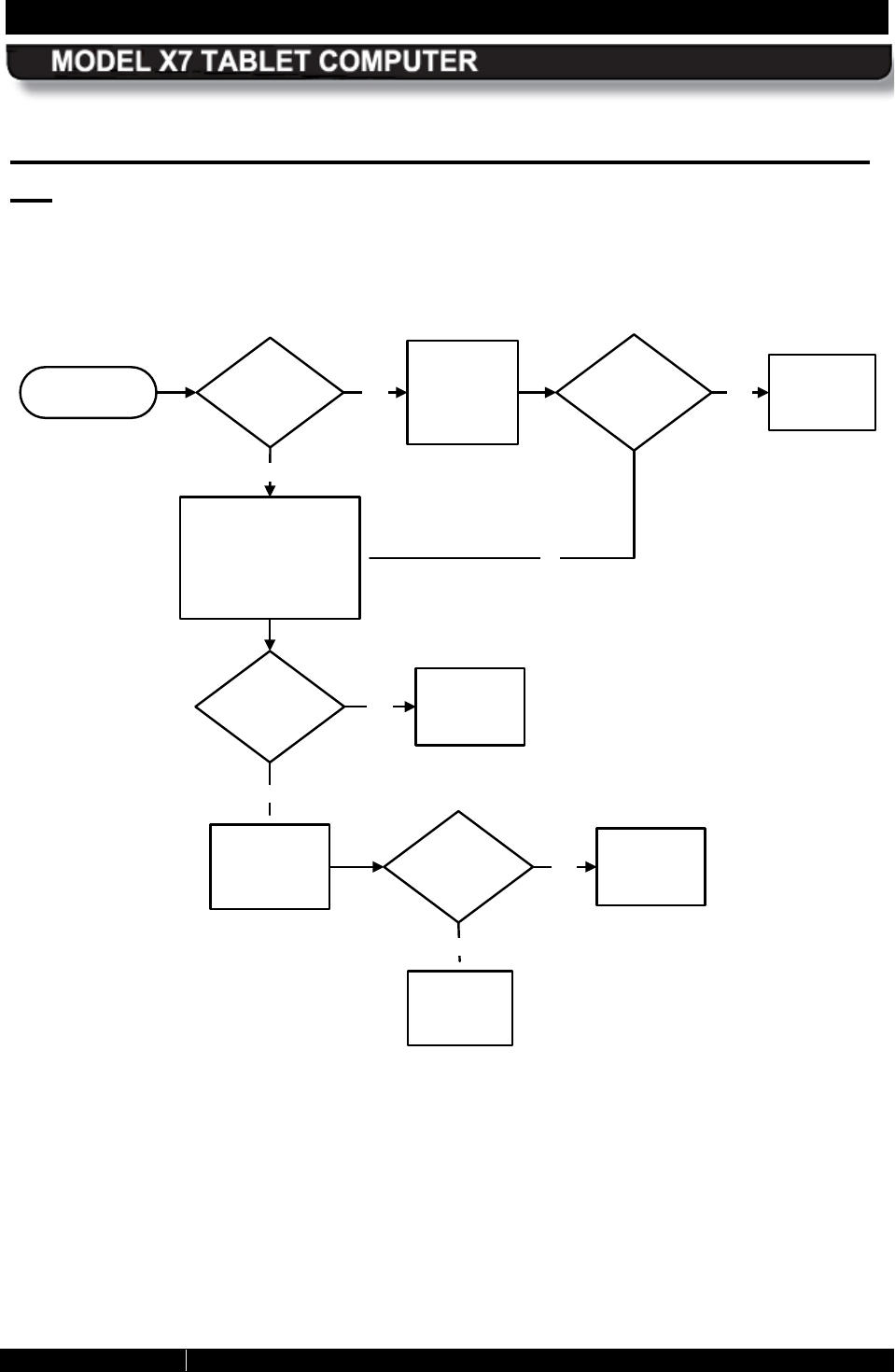
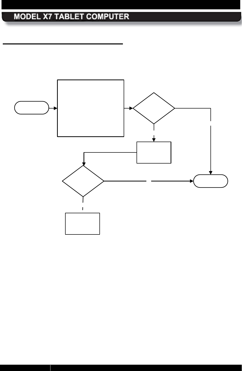
TS-02 Tablet will not start boot process. Power is
ok
Start Is tablet
docked? Yes Undock tablet
and attempt to
boot up.
No
1. Remove both
batteries and connect
tablet to docking station
or connect DC power
supply.
2. Attempt to boot up.
Did tablet
boot up? Yes
No
Send tablet
in for repair.
Does
tablet
boot up? Yes
No
Replace
batteries.
Temporarily
replace HD with
another HD.
Does
tablet
boot up? Yes
No
Re-image
HDD.
Send tablet
in for repair.
SECTION 6 TROUBLESHOOTING PAGE 155
9711-26400-0001
EXPORT CONTROLLED – SEE PAGE 3
Rev A
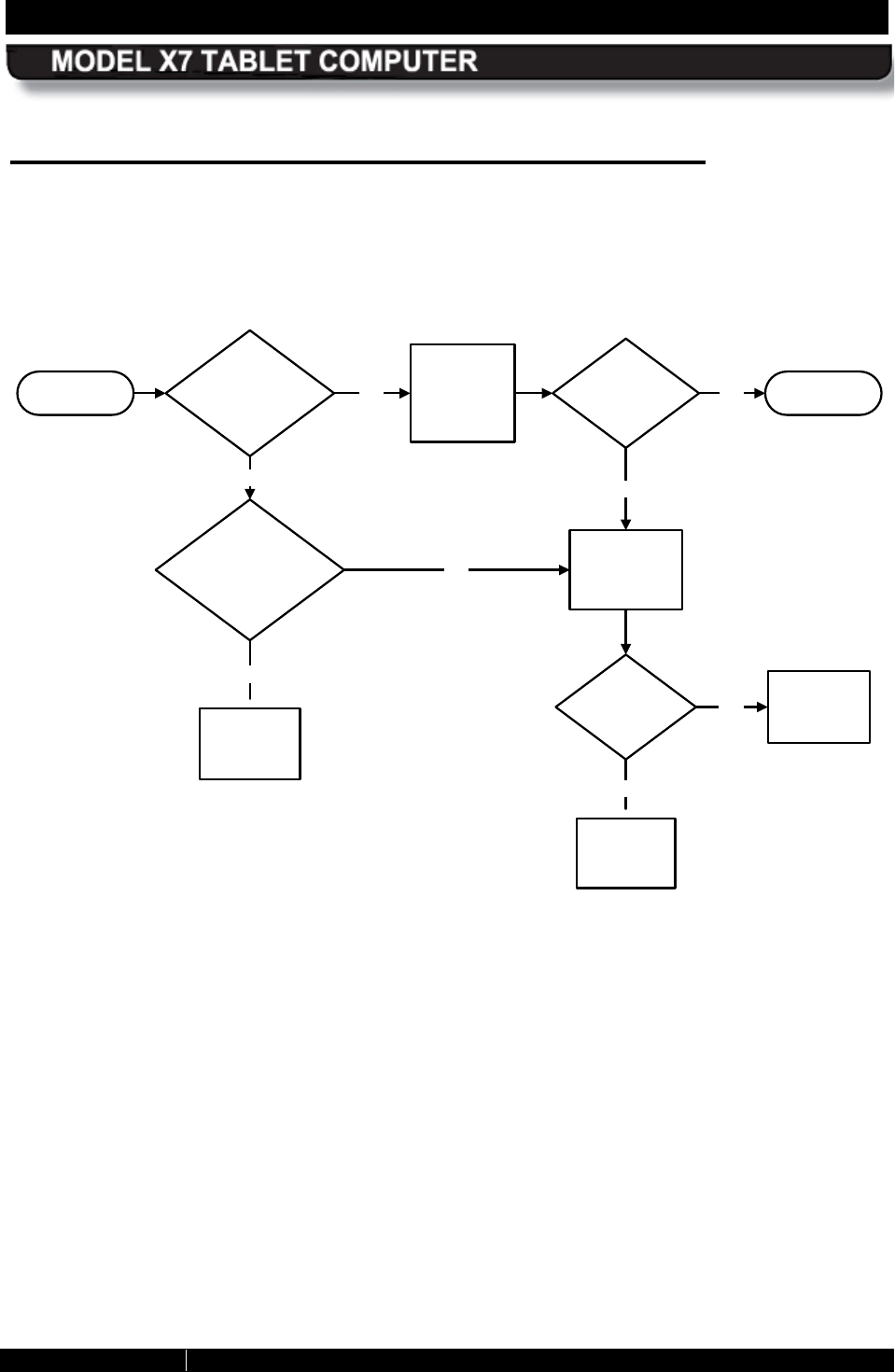
TS-03 Tablet will not boot into Windows
Does boot
process halt at
white flashing
cursor?
Yes Verify correct
boot device in
BIOS.
No
Does tablet
boot up?
No
Does tablet boot to
blue screen or does
screen go black? Yes
No
Temporarily
replace HD with
another HD.
Does
tablet
boot up? Yes
No
Send tablet
in for repair.
Send tablet
in for repair.
ExitYes
Re-image or
replace HDD.
Start
SECTION 6 TROUBLESHOOTING PAGE 156
9711-26400-0001
EXPORT CONTROLLED – SEE PAGE 3
Rev A
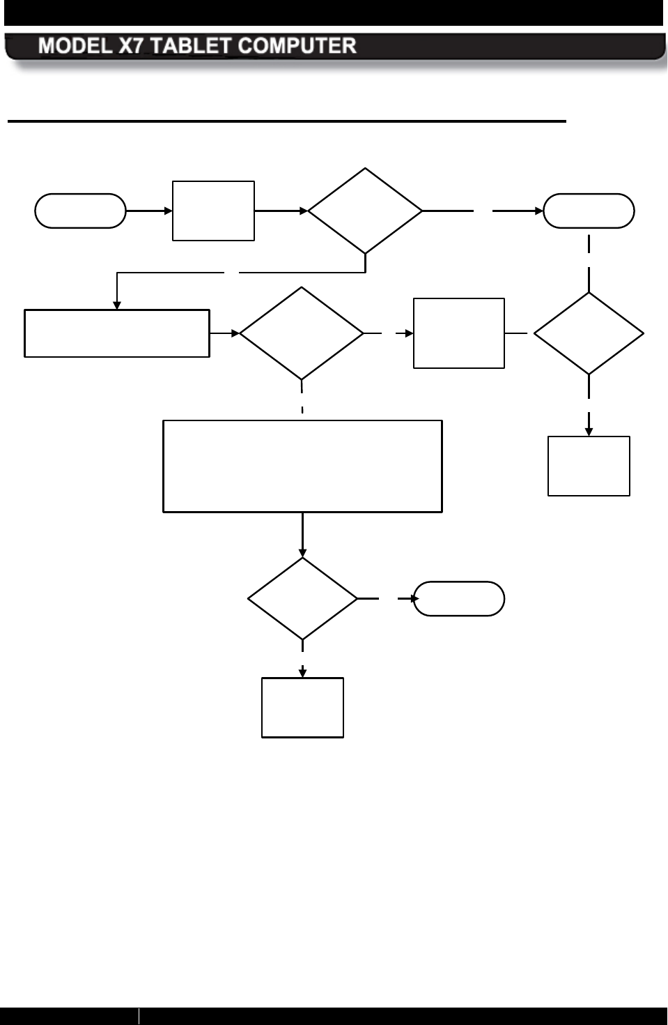
TS-04 Tablet will not recognize a battery
Start Does tablet
recognize
battery?
Yes
Exit
No
Recharge/
replace the
battery.
Flash the bios
Send tablet in
for repair.
Does tablet
recognize
battery?
Yes
No
Re-image/
replace the
hard drive.
Does tablet
recognize
battery?
No
Yes
No
Flash H8
Does tablet
recognize
battery?
Yes
SECTION 6 TROUBLESHOOTING PAGE 157
9711-26400-0001
EXPORT CONTROLLED – SEE PAGE 3
Rev A
TS-05 Tablet is locked up
Start
1. Shut down tablet.
2. Disconnect external
power.
3. Remove both batteries and
allow tablet to sit un-
powered for 5 minutes.
4. Re-insert batteries and/or
connect external power.
5. Reboot tablet.
Does tablet
Lock up?
No
Exit
Yes
Re-image/
replace HD.
Does tablet
Lock up?
No
Yes
Send tablet
in for repair.
SECTION 6 TROUBLESHOOTING PAGE 158
9711-26400-0001
EXPORT CONTROLLED – SEE PAGE 3
Rev A
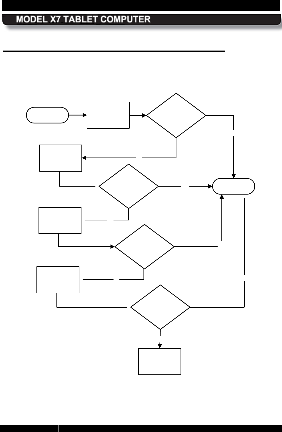
TS-06 Cannot connect to wireless network
Shut down and
reboot the
tablet.
Does tablet
Connect to
network?
No
Click on Start à Control Panel à
Network and Sharing Center.
Is a
red “X” present on
a connection
icon?
No
Yes
1. Click on Troubleshoot Problems.
2. Select Network Adapter.
3. Click on Next.
4. Select the network adapter to troubleshoot
5. Follow the on-screen instructions.
5. Reboot the tablet.
Exit
Yes
Start
Send tablet in
for repair.
Does tablet
Connect to
network?
No
Open
ARMORUtils and
click on the
Wireless Setup
option.
Exit
Yes
Send tablet in
for repair.
Is the
problem radio
disabled?
No
Yes

SECTION 6 TROUBLESHOOTING PAGE 159
9711-26400-0001
EXPORT CONTROLLED – SEE PAGE 3
Rev A
This Page Intentionally Left Blank
SECTION 7 MAINTAINING YOUR ARMOR X7 PAGE 161
9711-26400-0001
EXPORT CONTROLLED – SEE PAGE 3
Rev A
Table of Contents List of Figures List of Tables Acronyms Glossary
7. MAINTAINING YOUR ARMOR X7
R emoving and R eplacing the B atteries
CAUTION!
Only one battery at a time can be removed and replaced during
operation without causing system shutdown and possible loss of
data. Connect external power first before removing both batteries.
Table 22. Remove and Replace a Battery
STEP ACTION
1.
Push in on the battery lock button and slide the battery release to unlock the battery
and remove it.
2.
To install a battery, place the battery on the battery bay with the locking slots facing
toward the battery latch, as shown in Figure 88.
3.
Slide the battery toward the computer until the battery latch engages the slots in the
battery and the battery is flush against the compartment wall.
4.
Press firmly while moving the release button slightly until the battery locking button
snaps into place.
Figure 88. Replacing an X7 Battery
BATTERY
RELEASE
BATTERY
LATCH
BATTERY
LOCK BUTTON
LOCKING
SLOTS
SECTION 7 MAINTAINING YOUR ARMOR X7 PAGE 162
9711-26400-0001
EXPORT CONTROLLED – SEE PAGE 3
Rev A
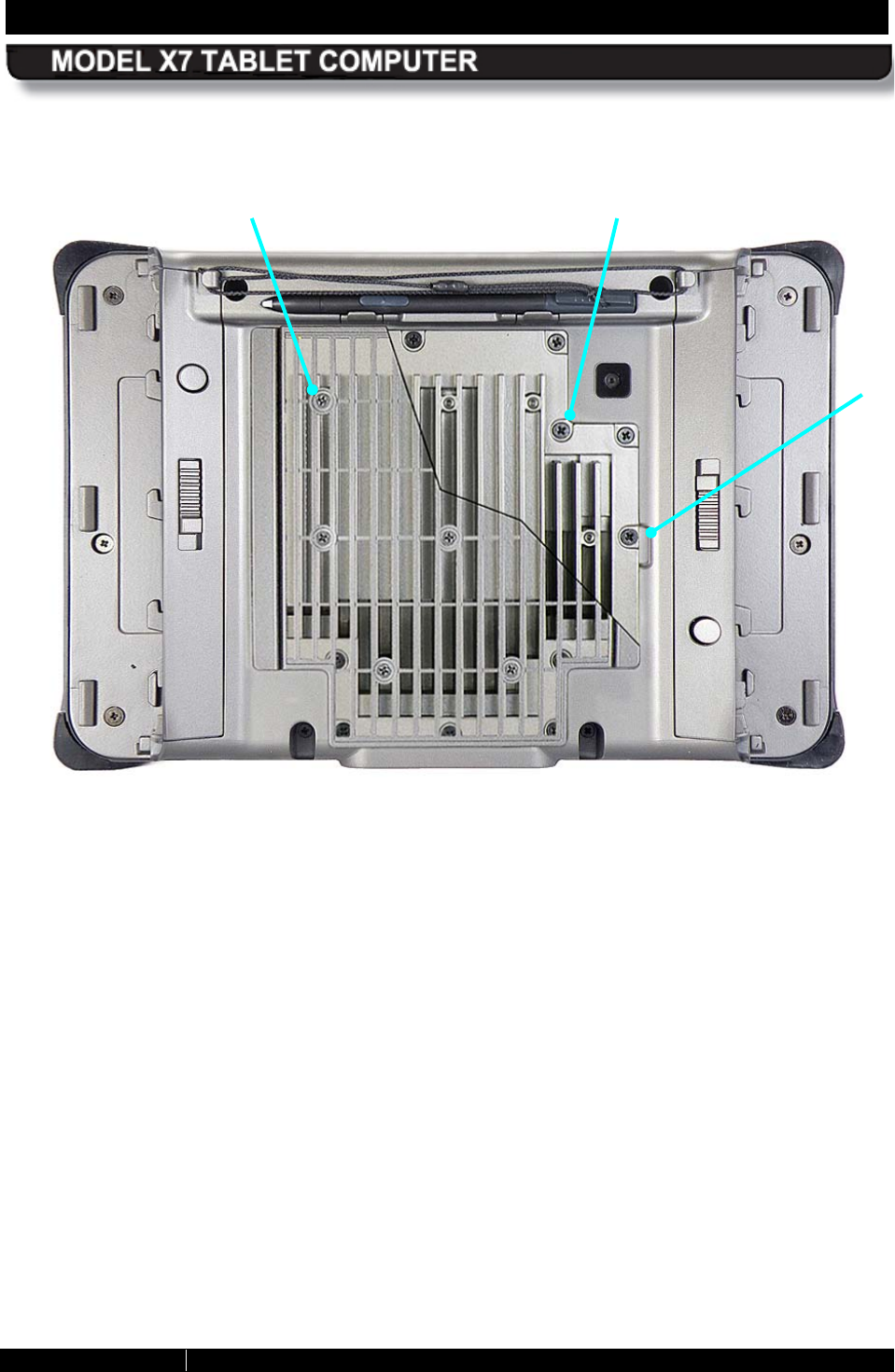
R emoving the Heat S hield and Cooling
R egister
Perform the procedure in Table 23 to properly remove the heat shield and cooling register. The
location of the heat shield and cooling register screws are shown in Figure 89 (NOTE: The heat
shield in this figure is shown cut away to expose the cooling register screws underneath).
CAUTION!
Circuit boards containing electrostatic discharge (ESD) sensitive
devices are exposed in this compartment. Static-free handling is
required to prevent possible damage to the components.
NOTE
This procedure should only be performed by a qualified
technician in a controlled environment.
Table 23. Removing the Heat Shield and Cooling Register
STEP ACTION
1.
Power down the computer and disconnect any external power.
2.
Remove the batteries.
3.
Place the computer face down on a clean surface and remove the 8 Philips screws
securing the plastic heat shield. Remove the shield.
4.
Remove the 14 Philips screws securing the cooling register.
5.
Carefully pry up the cooling register using the removal slot provided (Figure 89) and
remove.
SECTION 7 MAINTAINING YOUR ARMOR X7 PAGE 163
9711-26400-0001
EXPORT CONTROLLED – SEE PAGE 3
Rev A
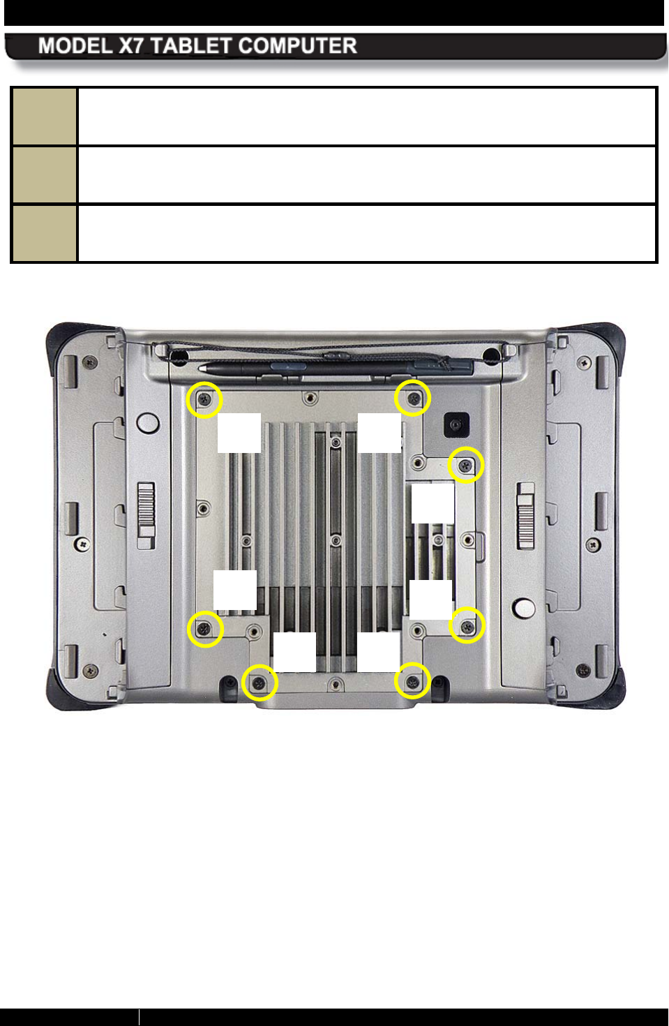
Figure 89. ARMOR X7 Cooling Register and Heat Shield Screws
HEAT SHIELD
SCREW (1 OF 8)
COOLING REGISTER
SCREW (1 OF 14)
REMOVAL
SLOT
SECTION 7 MAINTAINING YOUR ARMOR X7 PAGE 164
9711-26400-0001
EXPORT CONTROLLED – SEE PAGE 3
Rev A
Installing the Cooling R egister and Heat
S hield
Follow the procedure in Table 24 to properly install the cooling register and heat shield.
CAUTION!
The cooling register/cover is an integral part of the
environmental seal of the X7 tablet and must be installed
correctly using the procedure below. Failure to follow this
procedure could result in
poor heat transfer to the cooling
register and/or possible damage to the cooling register seal,
which could allow moisture and contaminants to enter the X7
interior.
CAUTION!
You must replace the previous thermal transfer pads with new
pads that were included with your X7 (P/N 0410F37171-0000). This
will maintain proper heat transfer from the mother board chip sets
to the cooling register. Do not reuse the old pads.
CAUTION!
Circuit boards containing electrostatic discharge (ESD) sensitive
devices are exposed in this compartment. Static-free handling is
required to prevent possible damage to the components.
NOTE
This procedure should only be performed by a qualified
technician in a controlled environment.
SECTION 7 MAINTAINING YOUR ARMOR X7 PAGE 165
9711-26400-0001
EXPORT CONTROLLED – SEE PAGE 3
Rev A
Table 24. Installing the Cooling Register and Heat Shield
STEP ACTION
1.
If either thermal pad (Figure 90) is torn or punctured, gently remove it, being
careful not to scratch the chip case.
Figure 90. Thermal Transfer Pads
THERMAL
TRANSFER PADS
SECTION 7 MAINTAINING YOUR ARMOR X7 PAGE 166
9711-26400-0001
EXPORT CONTROLLED – SEE PAGE 3
Rev A
STEP ACTION
2.
Obtain a transfer pads from the supply provided with your X7.
3.
Peel off the top and bottom protective layers of the pad and center it over the chip
surface using a pair of tweezers, as illustrated in Figure 91.
Figure 91. Placing a Thermal Pad
STEP ACTION
4.
Position the cooling register/cover
in place and press down gently to seat the
gasket.
5.
Insert 7 Philips screws in the circled locations shown in Figure 92 and tighten until
slightly snug. Do not fully tighten at this time.
SECTION 7 MAINTAINING YOUR ARMOR X7 PAGE 167
9711-26400-0001
EXPORT CONTROLLED – SEE PAGE 3
Rev A
6.
Once all 7 screws are installed, torque each screw to 2.8 kg-cm (2.4 in-lb) following
the numbered sequence indicated in Figure 92.
7.
Insert the remaining 7 Philips screws and torque to 2.8 kg-cm (2.4 in-lb) in any
sequence.
8.
Replace the heat shield and insert 8 Philips screws. Torque each screw to 2.8 kg-
cm (2.4 in-lb) in any sequence.
Figure 92. Cooling Register Initial Screw Placement
1
2
3
4
5
6
7
SECTION 7 MAINTAINING YOUR ARMOR X7 PAGE 168
9711-26400-0001
EXPORT CONTROLLED – SEE PAGE 3
Rev A
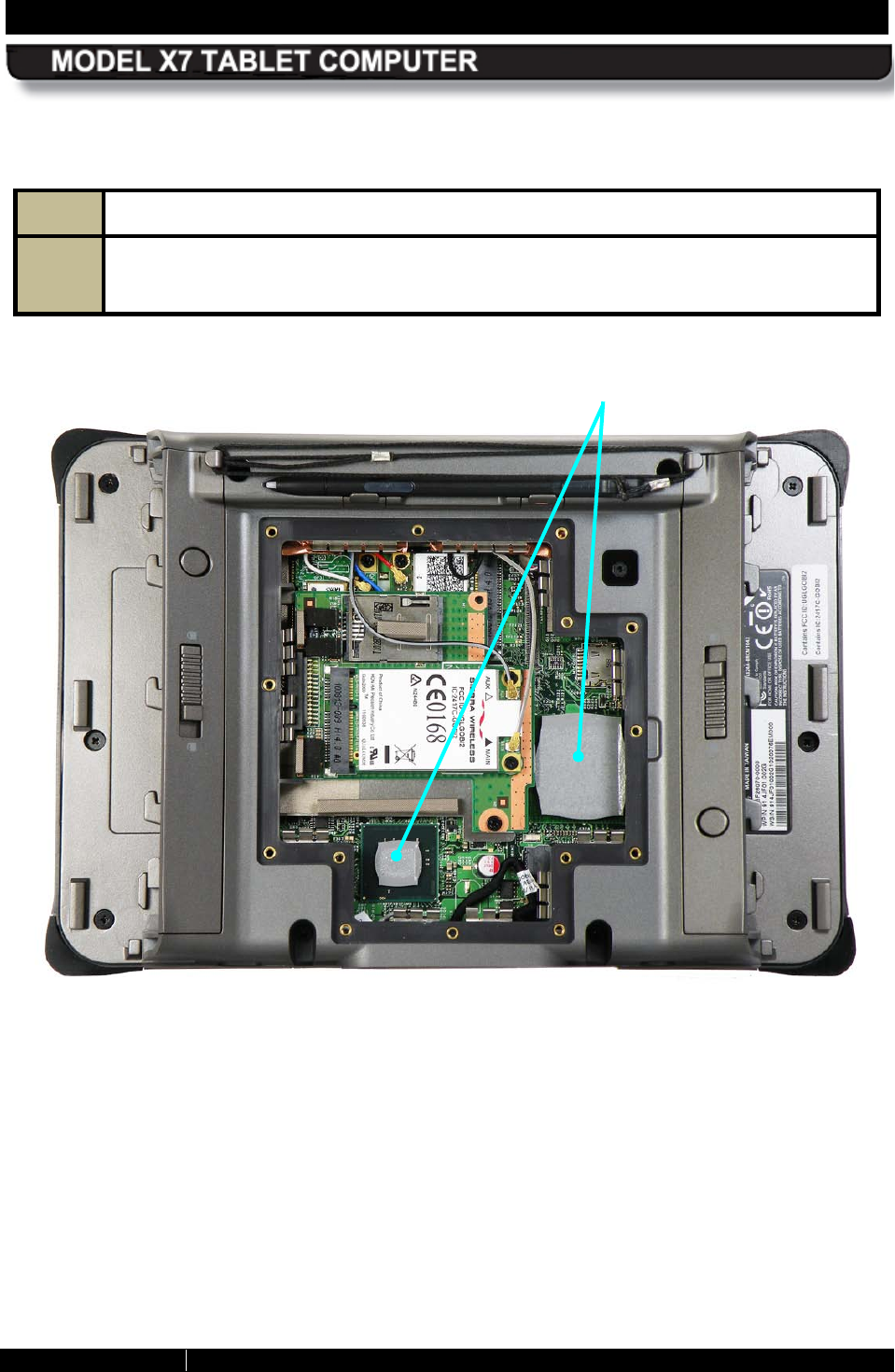
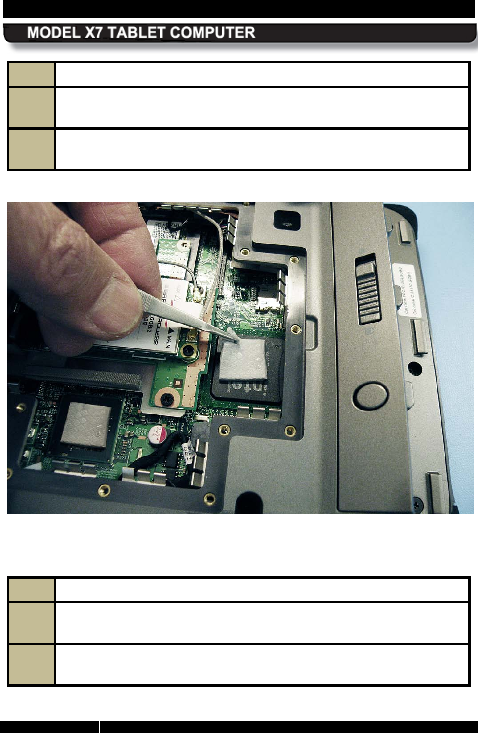
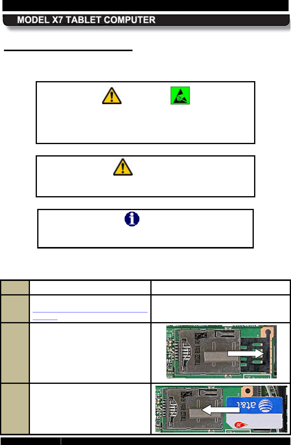
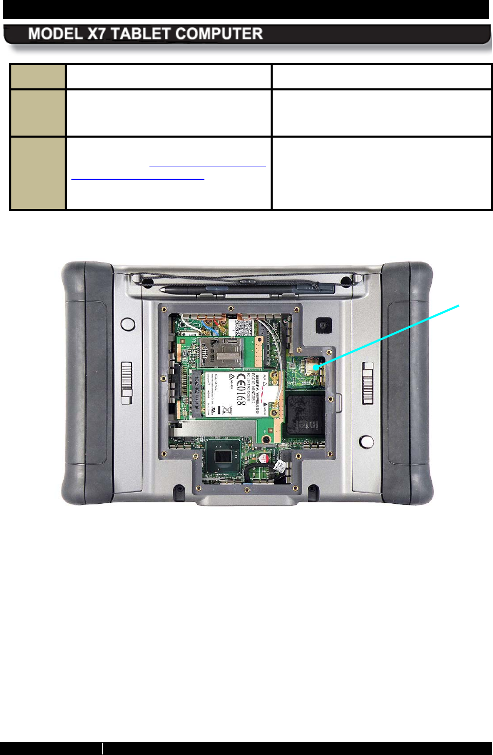
Ins talling a S IM Card
Follow the procedure in Table 25 to install your SIM card.
CAUTION!
Circuit boards containing electrostatic discharge (ESD) sensitive
devices are exposed in this compartment. Static-free handling
and processing is required to prevent possible damage to the
components.
CAUTION!
Use care when operating the X7 with the cooling register removed.
Internal voltages are exposed to possible short circuit.
NOTE
This procedure should only be performed by a qualified
technician in a controlled environment.
Table 25. Installing a SIM Card
STEP ACTION COMMENT
1.
First perform the procedure in
Removing the Heat Shield and Cooling
Register.
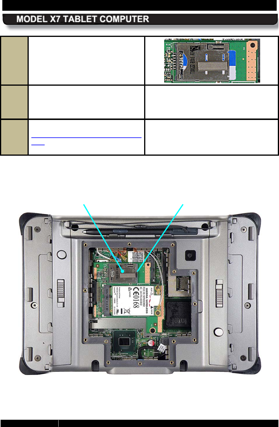
The SIM card is installed in a socket located
inside the X7, as shown in Figure 93.
2.
Remove the protective plastic insert
from the SIM card socket.
NOTE:
We recommend you save this
insert and reinstall it whenever there is
no SIM card in the socket.
This will
prevent accidentally deforming the
cover.
3.
Insert the SIM card with the corner
notch at the lower left as shown.
SECTION 7 MAINTAINING YOUR ARMOR X7 PAGE 169
9711-26400-0001
EXPORT CONTROLLED – SEE PAGE 3
Rev A
4.
Press in on the card until you feel the
eject spring lock into place.
5.
To remove the SIM Card, simply press
in on the right edge of the card until
the eject spring releases and pushes
the card out.
6.
Follow the procedure in
Installing the Cooling Register and
Heat Shield to properly re
install the
cooling register and heat shield.
Figure 93. SIM Card Socket Location
SIM CARD
SOCKET
PROTECTIVE
PLASTIC INSERT
SECTION 7 MAINTAINING YOUR ARMOR X7 PAGE 170
9711-26400-0001
EXPORT CONTROLLED – SEE PAGE 3
Rev A
Installing a Micro SD or S DHC Card
Follow the procedure in Table 26 to install your SD card.
CAUTION!
Circuit boards containing electrostatic discharge (ESD) sensitive
devices are exposed in this compartment. Static-free handling
and processing is required to prevent possible damage to the
components.
CAUTION!
Use care when operating the X7 with the cooling register removed.
Internal voltages are exposed to possible short circuit.
NOTE
This procedure should only be performed by a qualified
technician in a controlled environment.
Table 26. Installing the SD Card
STEP ACTION CONDITION OR INDICATION
1. First perform the procedure in
Removing the Heat Shield and
Cooling Register.
2. Carefully lift the micro SD socket cover
and insert the SD card all the way into
the cover.
NOTE: Due to the small size of the SD
card and the limited access space around
the socket, a pair of tweezers
or small
needle-nose pliers may be necessary to
insert the card.
3.
Gently press the cover with card down
onto the socket until it locks in place.
4.
Reinstall the batteries
or connect
external power.
SECTION 7 MAINTAINING YOUR ARMOR X7 PAGE 171
9711-26400-0001
EXPORT CONTROLLED – SEE PAGE 3
Rev A
STEP ACTION CONDITION OR INDICATION
5. Power up the X7 and click on Start
à
Computer
to verify that the card
appears as a new drive.
If the card does not appear, shut down
power, remove the card and reinsert it.
6. Shut down power and f
ollow the
procedure in
Installing the Cooling
Register and Heat Shield
to properly
reinstall the
cooling register and heat
shield.
Figure 94. Micro SD Card Socket Location
MICRO SD
CARD
SOCKET
SECTION 7 MAINTAINING YOUR ARMOR X7 PAGE 172
9711-26400-0001
EXPORT CONTROLLED – SEE PAGE 3
Rev A
Changing the B IOS Settings
Follow the procedure in Table 27 to access the BIOS setup utility and verify settings or make
changes. You can use the active pen (not a stylus or fingertip) to navigate the setup screens
and select options, or you can connect an external USB keyboard.
Contact DRS Technical Support if you have any questions about the BIOS settings for your
ARMOR X7.
CAUTION!
Incorrectly setting the BIOS options could cause the X7 to become
unstable or render it completely inoperable. Move carefully through
the menus and use caution when making changes. Read the
description of each change in the right-hand column before making
any adjustments.
NOTE
If you make permanent changes as a result of an upgrade or
addition of new
equipment, be sure to keep a record of the
changes. Table 28 provides a handy place to record these changes.
Always record the previous value in case you have to return to that
value.
Table 27. Access the BIOS Setup Utility.
STEP ACTION
1.
You can use the active pen to navigate in the BIOS setup screens or you can attach a
USB keyboard to the USB port on the right side of the computer.
2.
Start the computer and as soon as the DRS logo appears, tap on the screen until you
hear a beep. A small options menu will be displayed.
3.
Select Launch System Setup to open the Setup Utility main screen.
4.
Use the LEFT and RIGHT ARROW keys to highlight the desired menu page (listed at
the top of the screen) and press ENTER to select the menu.
5.
Use the UP and DOWN ARROW
keys to scroll through the page settings and to
highlight a particular setting or sub-option.
SECTION 7 MAINTAINING YOUR ARMOR X7 PAGE 173
9711-26400-0001
EXPORT CONTROLLED – SEE PAGE 3
Rev A
6.
Select ENTER to access the sub-options under a highlighted option. Press ESC to
return to the previous option or menu.
7.
Use the F5 and F6
keys to cycle through the available options and highlight the
desired value to change.
8.
Select ESC to exit the option.
9.
Use the arrow keys to move to the next option.
10.
When all changes have been made, select F10 to exit and save your changes or
select ESC to exit without saving any changes. The computer will resume booting.
Table 28. Record Bios Changes Here
SETTING PREVIOUS
VALUE NEW
VALUE
DATE
CHANGED
SECTION 7 MAINTAINING YOUR ARMOR X7 PAGE 174
9711-26400-0001
EXPORT CONTROLLED – SEE PAGE 3
Rev A
R eturning the B IOS to its Default S ettings
When your X7 was shipped to you, the BIOS settings were set to a “default” state for your
particular configuration. To return the BIOS to this default state, follow the procedure in Table
29.
NOTE
Defaulting the BIOS will
change the brightness control to the
“Automatic” adjustment mode. To change the adjustment to
manual mode, open the Backlight Setup in ARMORutils and select
Manual mode.
Table 29. Return the BIOS to Its Default State
STEP ACTION
1.
Access the BIOS Setup Utility (see Changing the BIOS Settings for instructions on
how to access the Setup Utility).
2.
Press F9 to load the default BIOS configuration.
3.
Press F10 to save your changes and exit.
SECTION 7 MAINTAINING YOUR ARMOR X7 PAGE 175
9711-26400-0001
EXPORT CONTROLLED – SEE PAGE 3
Rev A
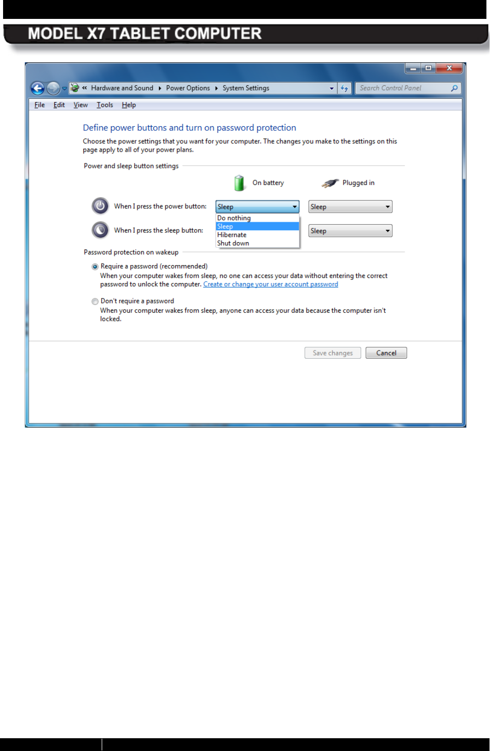
Changing the Power B utton Default A ction
Follow the procedure in Table 30 to change the default actions of the Power button.
NOTE
This change will only affect the action of the Power button during
the operating state; it will still work the same as described in Table
1
when the computer is powered off or is in sleep or hibernate
mode.
Table 30. Changing the Power Button Default Actions
STEP ACTION CONDITION OR INDICATION
1.
Select Start
à
Control Panel
à
Hardware & Sound
à
Power
Options
The Power Options dialog window is
displayed.
2.
From the left panel, select Choose
what the power buttons do.
The Systems Settings window opens as
shown in Figure 95.
NOTE
The X7
does not have a Sleep
button so ignore the bottom set
of options.
3.
Click on the pull-
down menus in the
On battery and Plugged in columns
and select the desired action.
The pull-down menu options are shown in
Figure 95.
4.
Click on the Save Changes
button at
the bottom of the window.
SECTION 7 MAINTAINING YOUR ARMOR X7 PAGE 176
9711-26400-0001
EXPORT CONTROLLED – SEE PAGE 3
Rev A
Figure 95. System Settings - Power Button Options
SECTION 7 MAINTAINING YOUR ARMOR X7 PAGE 177
9711-26400-0001
EXPORT CONTROLLED – SEE PAGE 3
Rev A
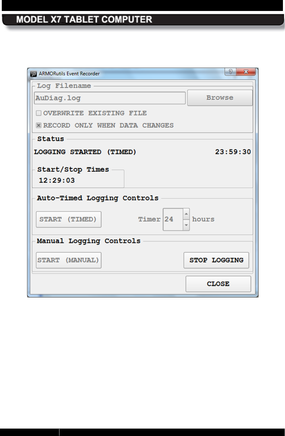
Creating an E vent Log
If you are experiencing problems and suspect that they are temperature or battery related, you
can create a log of the internal temperature and battery status of the X7 over time using the
Event Recorder function in the ARMORutils Diagnostics window. Follow the procedure in Table
31 to create an event log.
Table 31. Creating an Event Log
STEP ACTION CONDITION OR INDICATION
1.
Open ARMORutils and select the
Diagnostics option. The Diagnostics dialog window opens, as
illustrated in Figure 65.
NOTE
If the Event Recorder
button is
grayed out, you must enable it in
the User Access Settings
window. Refer to the description
of the User
Access Settings
Window for instructions.
2.
Click on the EVENT RECORDER
button at the bottom of the window. The Event Recorder
window opens as
shown in Figure 96. NOTE:
The initial
status will reflect the start and stop times
recorded with the last logging. These will
update when you start your new event
log.
3.
If you wish to change the current file log
name, edit it at this time. Click on the
BROWSE
button to navigate to a
different file or folder.
4.
For Auto-Timed logging, enter the hours
directly in the Timer
menu window or
use the up/down arrows to select the
time and then click on START (TIMED).
5.
For Manual logging, click on START
(MANUAL).
6.
To stop the logging process in either
Auto-
Timed or Manual mode, click on
the STOP LOGGING button.
A sample event log is shown in Figure 67.
SECTION 7 MAINTAINING YOUR ARMOR X7 PAGE 178
9711-26400-0001
EXPORT CONTROLLED – SEE PAGE 3
Rev A
Figure 96. Diagnostics Event Recorder Window
SECTION 7 MAINTAINING YOUR ARMOR X7 PAGE 179
9711-26400-0001
EXPORT CONTROLLED – SEE PAGE 3
Rev A
Caring For the Dis play S creen
The following tips will help you keep your display clean and healthy:
CAUTION!
Use only canned compressed air to clean your screen. Do not use
an air compressor. Damage to the screen surface could result.
CAUTION!
Do not attempt to remove stuck particles with a fingernail or other
hard object as this can permanently damage the touch screen
surface.
• Do not use an abrasive or metallic pointer on the screen surface as this may damage the
screen. Use the pen included with your X7, a passive stylus designed for touch screens
(not included), or your fingertip.
• Use alcohol or a plastic cleaner such as Plexus™ to clean the pen tip.
• Be careful not to let sand or grit stay on the screen as this can scratch the surface when
wiped with a cloth. Use canned compressed air or a soft bristle brush to remove loose
particles before wiping with a cloth.
• Use the special micro-fiber ARMOR cloth that came with your X7 to wipe away dust and
fingerprints.
• For stubborn residue, clean the surface with plain water or water with a few drops of dish
soap added and pat dry with a clean paper towel or cloth, then use the special ARMOR
cloth that came with your tablet to remove any remaining residue.
• Use a cotton swab with plain water, soapy water or alcohol to gently remove particles
stuck to the surface.

SECTION 7 MAINTAINING YOUR ARMOR X7 PAGE 180
9711-26400-0001
EXPORT CONTROLLED – SEE PAGE 3
Rev A
Cleaning the Tablet Case
• Use a clean cloth dampened with water to wipe down the case.
• For stubborn dirt or contaminants, use a cloth dipped in plain or soapy water. Remove
any soap residue with a clean cloth dampened in plain water.
• Wipe out battery compartments using a clean dry cloth. Use a soft bristle brush or
canned air to remove loose particles.
• Batteries can be cleaned in the same way.
• To clean the cooling register, first remove the heat shield and then clean with a damp
cloth or soapy water. Remove any soap residue.
SECTION 8 DISPLAY MANAGEMENT PAGE 181
9711-26400-0001
EXPORT CONTROLLED – SEE PAGE 3
Rev A
Table of Contents List of Figures List of Tables Acronyms Glossary
8. DISPLAY MANAGEMENT
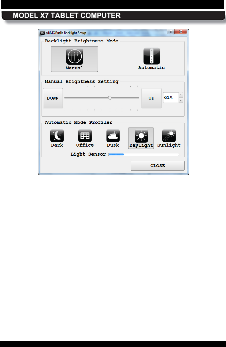
Adjusting the B rightness
The brightness of an LCD display is controlled by adjusting the intensity of the backlight. The
backlight level for the X7 can be controlled manually or automatically. When you first receive
your X7, the brightness mode is set to “Automatic”.
Automatic B rightnes s Adjus tment
Open the Backlight Setup dialog in ARMORutils and click on the Automatic button. The
backlight level will now be controlled by the automatic light sensor (ALS). If the surrounding light
decreases, the brightness will also decrease proportionally; if the surrounding light increases,
the brightness will increase proportionally.
NOTE
You must
keep the ALS uncovered to allow proper automatic
brightness adjustment.
Automatic B rightnes s Mode P rofiles
Select one of the profiles that best controls the range of backlight levels to suit your work
environment. Refer to Automatic Brightness Mode Profiles for an explanation of these profiles.
Manual Brightness Adjustment
Click on the Manual button to change to manual brightness mode. You can manually adjust
screen brightness in two ways: by using programmable buttons (PBs) P1, P2 and P3 or by
using options and buttons in the Backlight Setup dialog in ARMORutils.
Us ing the PBs
NOTE: ARMORutils must be running in order to use these programmable buttons (see Starting
ARMORutils).
Repeatedly press P1 to increase screen brightness. Repeatedly press P2 button to decrease
screen brightness. Press P3 to toggle the screen on and off.
Us ing the AR MOR utils B acklight S etup Dialog
Open ARMORutils and select the Backlight Setup button. The Backlight Setup dialog opens as
shown in Figure 97.
SECTION 8 DISPLAY MANAGEMENT PAGE 182
9711-26400-0001
EXPORT CONTROLLED – SEE PAGE 3
Rev A
Figure 97. Armor Utilities Screen – Backlight Tab
Press the UP or DOWN buttons repeatedly or use the pen or a fingertip to move the slider and
adjust the backlight level. The % brightness is displayed in a field on the right. You can also use
up and down arrows next to this field to adjust the slider.
SECTION 8 DISPLAY MANAGEMENT PAGE 183
9711-26400-0001
EXPORT CONTROLLED – SEE PAGE 3
Rev A
Calibrating the Dis play
To access both touch screen and pen screen calibration routines, open ARMORutils and click
on the Screen Setup option (see Figure 63). If the display is in Dual Mode, both calibration
options will be available (contrasted). If the display mode is touch or pen only, only that screen
calibration option will be available.
To Calibrate the Touch S creen
Select the Touch option in the Calibration panel to open the Touch Settings window then click
on the Calibrate button to open the calibration screen. Follow the on-screen instructions.
To Calibrate the Pen Screen
Select the Pen option in the Calibration panel to open the Pen Tablet Properties window. Select
the Calibrate tab and click on the Calibrate button to open the calibration screen. Follow the
on-screen instructions.
SECTION 8 DISPLAY MANAGEMENT PAGE 184
9711-26400-0001
EXPORT CONTROLLED – SEE PAGE 3
Rev A
R otating the Screen (Touch or Pen)
Your ARMOR X7 supports the Windows function of rotating the screen between Landscape and
Portrait layout mode. In landscape mode (default orientation), the long axis of the screen is
along the top and bottom of the display. In portrait mode, you turn the computer 90° and the
long axis of the screen is along the left and right sides of the display.
There are three ways to rotate the screen:
• By using the Intel Graphics options via the desktop or icon tray
• By using the Intel Graphics and Media Control panel
• By using a hot key combination with an external keyboard
NOTE
If you lose calibration when rotating the screen and cannot use the
pen to return to the default orientation, attach an external keyboard
and press Ctrl+Alt+Up Arrow. This will return the display to the
default landscape orientation.
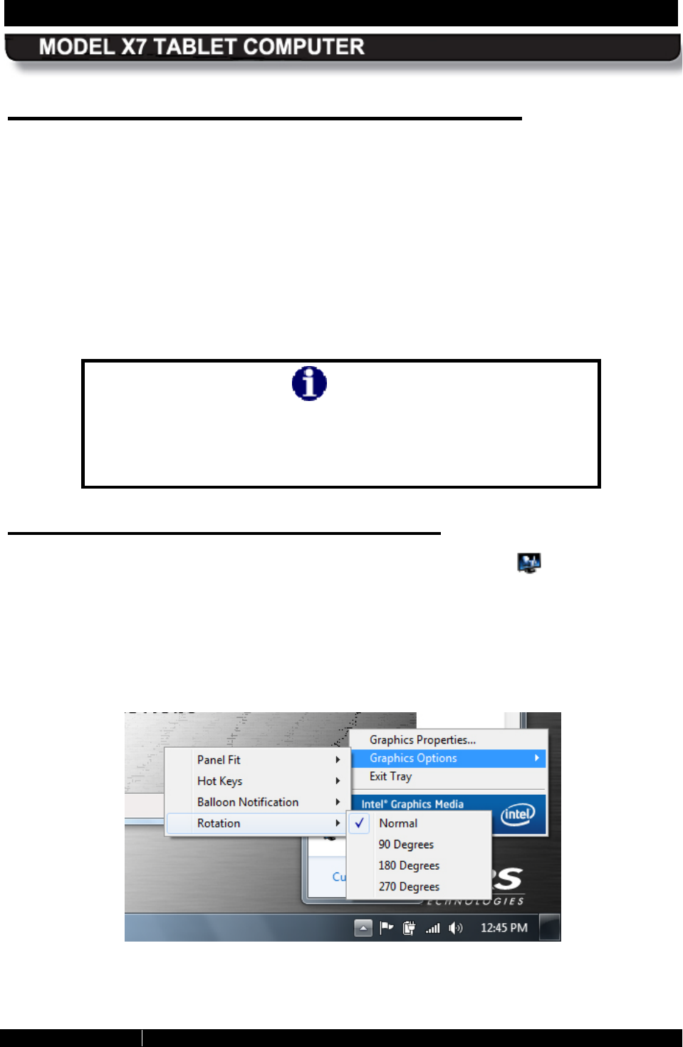
Us ing the Intel Graphics Options
Right click anywhere on the desktop or click on the Intel Graphics icon in the systray and
select Graphics Options à Rotation. Then select one of the four rotation angles as shown in
Figure 98. NOTE: The “Normal” position is the landscape screen orientation with the tablet held
as shown in Figure 1.
You can rotate the screen clockwise in four 90° steps, alternating between portrait and
landscape orientation, or you can rotate it 180° or 270°.
Figure 98. Intel Graphics Screen Rotation Options (from the systray)
SECTION 8 DISPLAY MANAGEMENT PAGE 185
9711-26400-0001
EXPORT CONTROLLED – SEE PAGE 3
Rev A
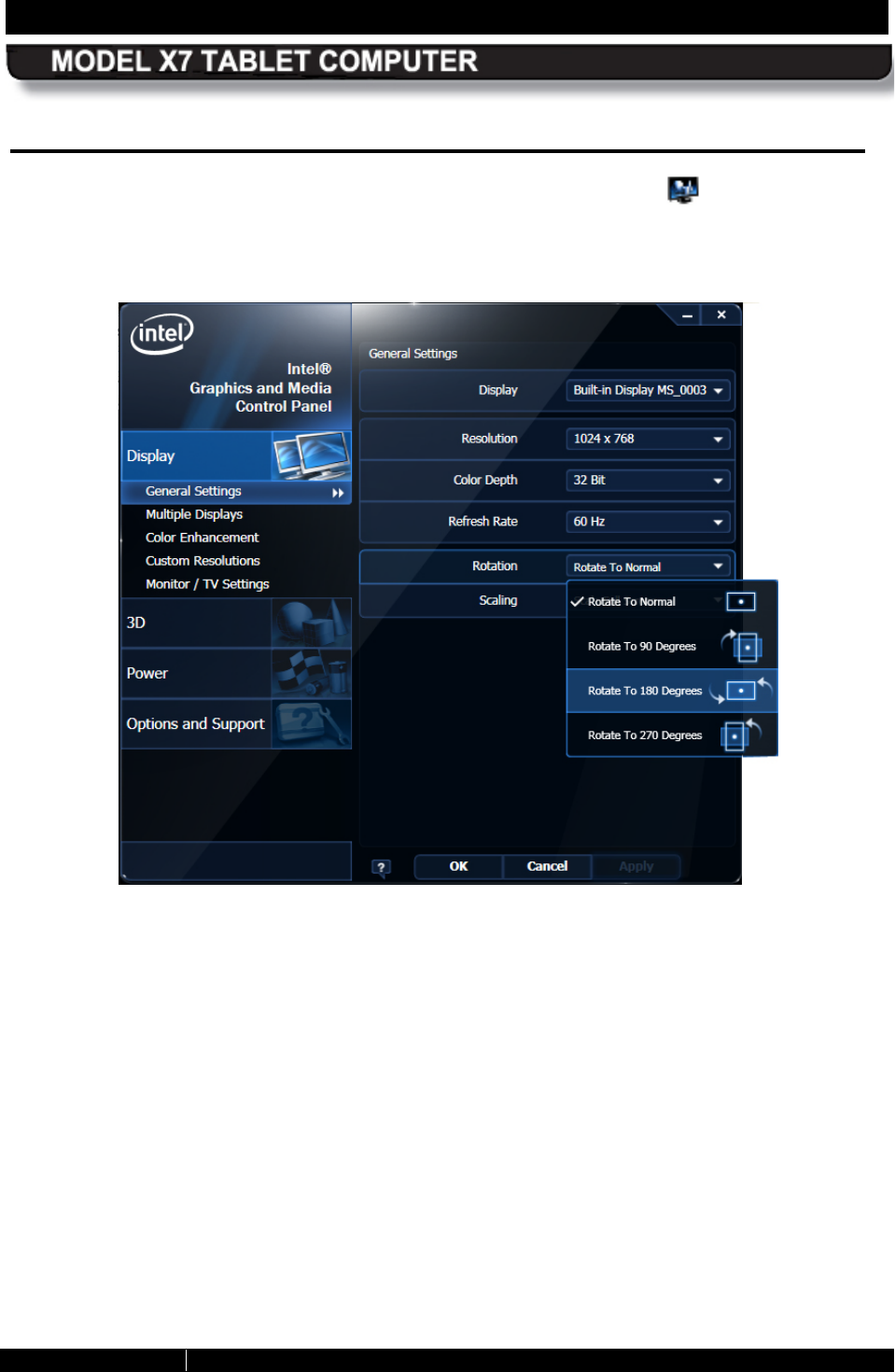
Us ing the Intel Graphics and Media Control Panel
Right-click anywhere on the desktop or click on the Intel Graphics icon in the icon tray and
select Graphics Properties to open the Intel Graphics and Media Control Panel, as shown in
Figure 99. Select the rotation angle and click OK.
Figure 99. Intel Graphics and Media Control Panel
SECTION 8 DISPLAY MANAGEMENT PAGE 186
9711-26400-0001
EXPORT CONTROLLED – SEE PAGE 3
Rev A
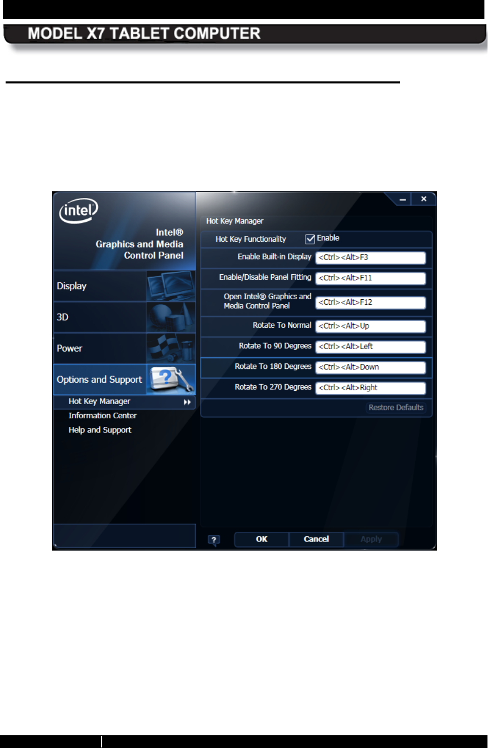
Us ing a K eyboard “Hot K ey” Combination
Open the Intel Graphics and Media Control Panel and select Options and Support à Hot Key
Manager. A list of pre-assigned (default) hot key combinations is displayed in the right panel, as
shown in Figure 100. You can use these default combinations or specify a combination of your
own.
To use a hot key combination, connect a USB keyboard and enter the combination.
Figure 100. Intel Graphics Panel Hot Key Manager
SECTION 9
BATTERY MANAGEMENT
PAGE 187
9711-26400-0001
EXPORT CONTROLLED – SEE PAGE 3
Rev A
Table of Contents List of Figures List of Tables Acronyms Glossary
9. BATTERY MANAGEMENT
The Lithium Ion batteries used in your ARMOR X7 computer offer the best technology available
today. These ‘Smart Batteries’ provide ARMOR X7 users with the greatest power density and
the most accurate “fuel gauge” possible. To achieve the best possible performance from your
batteries, we recommend using and maintaining the batteries in accordance with the
instructions provided in this section.
WARNING!
Do not drop or mishandle the batteries, immerse them in water, or
subject them to high heat. Doing so could increase the risk of
explosion or leakage, and possibly cause injury.
WARNING!
The lithium-
ion batteries used in this equipment contain material
that is hazardous to your health. If battery contents come in contact
with the eyes, IMMEDIATELY flush the affected area with clean
water for 15 minutes and have someone else summon medical
attention for you. Unaffected persons should assist the affected
individual in the vital first flushing of the eyes.
WARNING!
If battery material comes in contact with the skin, flush the affected
area with clean water and seek immediate medical treatment.

SECTION 9
BATTERY MANAGEMENT
PAGE 188
9711-26400-0001
EXPORT CONTROLLED – SEE PAGE 3
Rev A
Safety and Handling Considerations for Your
B atteries
Please use the following safety rules when handling and using lithium-Ion batteries.
• Do not expose the batteries to very high temperatures such as an open flame.
• Do not short circuit the battery contacts or reverse their polarity.
• Do not let children play with the batteries.
• Do not crush, dent or allow any deformation of the batteries.
• Do not disassemble or open the batteries or try to alter or bypass the internal safety
circuits.
• Avoid exposing the batteries to wet or extremely humid conditions.
• Avoid exposing the batteries to electrostatic discharge.
• Avoid dropping the batteries.
• Do not use in, or connect the batteries to, any other devices.
• Do not allow removed batteries to remain discharged for more than 1 week
SECTION 9
BATTERY MANAGEMENT
PAGE 189
9711-26400-0001
EXPORT CONTROLLED – SEE PAGE 3
Rev A
When to Charge a B attery
New B atteries
DRS recommends that you fully charge your batteries before using them for the first time in your
computer. Due to current regulations regarding shipment of lithium Ion batteries, your X7
batteries are shipped to you in a partially charged condition, typically with a maximum charge of
30%-50%.
If you do not plan to use your computer immediately, be aware that the batteries can discharge
as much as 4% in 24 hours if left in the computer with the power turned off. For this reason, we
recommend that computers with the batteries installed, that will not be used for an extended
period of time, be connected to external power, either using the AC adapter provided with your
computer or through a docking station using vehicle power.
Currently Ins talled B atteries
Your ARMOR X7 will alert you when your batteries need charging. When the remaining charge
drops below 10%, an alert message like the one shown in Figure 101 will pop up on the
desktop. You should connect external power to recharge the batteries or replace them as soon
as possible.
To check the current charge level of your installed batteries, click on the battery icon in the
systray. This will open a desktop battery window like the one shown in Figure 103. NOTE: the
battery icon will change to a battery with plug icon when external power is connected).
You can also select the Battery Monitor button on ARMORutils main page. This will open the
Battery Monitor dialog window (Figure 59) where you can check the current status and the
remaining charge of your batteries.
R emoved B atteries
To check the remaining charge of a battery that is removed from the computer, press the fuel
gauge button to activate the fuel gauge (see Figure 26).
The lowest charge level indicator (#1) will flash when the battery is at 10% charge or below. If
you get this indication, install the battery in your computer and connect external power, or you
can recharge the battery in the optional X7 external battery charger (see Using the X7 External
Battery Charger).
Removed batteries will continue to self-discharge even when disconnected from the computer.
The lower the charge level, the sooner the battery will approach the fully depleted state. DRS
recommends you recharge removed batteries as soon as possible.
Depleted B atteries
When an installed battery’s charge drops below 10%, a warning message, similar to the one in
Figure 101 will appear on the desktop. At this point, the battery is in a “depleted” charge state
(between 10% and 5%). When the total charge drops below 7%, another warning message will
be displayed advising you to connect external power immediately. If the total charge drops
below 5%, the computer is programmed to automatically enter the hibernate state. Your
SECTION 9
BATTERY MANAGEMENT
PAGE 190
9711-26400-0001
EXPORT CONTROLLED – SEE PAGE 3
Rev A
Windows session will be saved to the mSATA drive and the computer will shut down to
conserve power.
To avoid having your computer suddenly enter the hibernate mode, you should connect
external power to recharge your batteries as soon as you see the low battery warning message,
or replace them immediately with fresh batteries. You should also arrange to recharge any
depleted batteries as soon as practical.
CAUTION!
If batteries are allowed to continue discharging below the 10% level,
it is possible that high current demand on the batteries could cause
the remaining charge to drop below 5% before Windows can initiate
the hibernate process at the 5% level. This can result
in the
computer shutting down unexpectedly with the loss of your session.
Depleted B atteries Left in the Computer
Lithium ion batteries left in a computer with the power off will discharge at approximately 4%
over a 24 hour period. Therefore, a depleted battery can become fully depleted or possibly
overly discharged in about two days.
Depleted Batteries R emoved from the Computer
A lithium battery that is not installed in the X7 will self discharge at the rate of about 0.3% in a
24 hour period or about 3% every 10 days (faster in higher temperature conditions). A depleted
battery that is removed is therefore in danger of becoming fully depleted, or possibly overly
discharged, in about 30 days.
Fully Depleted and Overly Discharged Batteries
A lithium battery is considered fully depleted when its charge level falls below 3%. When a
battery becomes fully depleted, the LEDs on the fuel gauge may not light but it is still possible to
recover it if you recharge it immediately. If a fully depleted battery is not recharged soon enough
(generally within 24 hours), it can enter an overly discharged state in which it will not respond to
normal efforts to recharge it.
Un-recoverable Batteries
If the charge level is allowed to drop to around 0% and the battery is not soon recharged, a
safety circuit inside the battery can activate and render the battery un-recoverable. To avoid this
possibility, DRS recommends you recharge any battery that reaches the fully depleted state
(<3% charge) as soon as possible.
SECTION 9
BATTERY MANAGEMENT
PAGE 191
9711-26400-0001
EXPORT CONTROLLED – SEE PAGE 3
Rev A
CAUTION!
Batteries that are allowed to continue discharging after reaching
the 3% charge level may become un-recoverable and have to be
discarded.
Avoiding Overly-Discharging Your B atteries
The following suggestions will help avoid an overly-discharged condition.
• Do not store the X7 for long periods with the batteries installed without connecting
external power. Even when the unit is powered off, the tablet still draws a small amount
of power from the batteries.
• Do not store X7 batteries in a fully depleted condition for long periods of time. The X7
batteries will further self-discharge over time at a rate of about 3% every 10 days or
about 10% a month. For long-term storage, the batteries should be recharged to at least
40% of full charge every 3-4 months of storage.
What to Do for an Overly-Dis charged B attery
The X7 has an internal Level 2 smart battery charger. One of the features of this charger is that
it will attempt to recover a battery that has been too deeply discharged (<3%). This is done by
applying a trickle current of 80 milliamps for about 3 minutes. This process normally injects
enough energy into the battery to allow normal re-charging to begin. If the recovery process is
successful, the Charging/Fault LED will begin flashing. Allow the battery to charge normally.
If the Charging/Fault indicator does not light, perform the recovery procedure in Table 32.
Table 32. Recovering an Overly-discharged Battery.
STEP ACTION
1.
Remove the depleted battery and wait 5 seconds.
2.
Reinstall the battery and allow it to charge.
3.
If the battery does not respond, repeat the above steps up to a maximum of five
times.
4.
If the battery still fails to start charging, it will have to be replaced.
SECTION 9
BATTERY MANAGEMENT
PAGE 192
9711-26400-0001
EXPORT CONTROLLED – SEE PAGE 3
Rev A
How to C harge Your Batteries
The X7 batteries automatically begin charging when installed in the computer and external
power is applied. To recharge the batteries using the computer, plug the circular connector of
the AC adapter into the DC power input jack on the left side of the ARMOR X7, or into the PWR
connector on a desk dock unit. If your X7 is installed in a vehicle dock, the batteries will charge
whenever vehicle battery power is available.
Don’t be alarmed if batteries feel warm to the touch during the charging process. Your X7
batteries are protected from being overcharged by internal safety circuits.
Charging Times
The charging time for one or two fully depleted batteries (10% charge or less) when the
batteries are installed in the X7 will depend primarily on the following:
• power demands on the system (screen brightness setting, wireless and GPS radio
activity, utility and software applications currently running, etc.)
• temperature extremes
• number of batteries (1 or 2)
• total remaining capacity of each battery
Two types of batteries are available for the X7: a standard type with 2950 mAh capacity and a
high-capacity type with 5900 mAh capacity. Table 33 lists typical charging times for each battery
type.
NOTE
The charging cycle is not linear and the last 20% of charge can take
proportionally longer to complete than the first 80% of charge time.
Table 33. X7 Battery Charging Times
Number of
Batteries High-Capacity (5900 mAh)
P/N 0300-50842-0000
Standard (2950 mAh)
P/N 0300-50842-0001
2 7 hours 3
1 3 hours 1.5
Charging Temperatures
DRS has included temperature sensors in the battery circuit to protect the cells when a high or
low temperature condition occurs. Your batteries will charge normally in the X7 computer so
long as the internal temperature remains above 0°C (32°F) and does not exceed 45°C (113°F).
If the internal temperature moves outside these limits during charging, the computer will
SECTION 9
BATTERY MANAGEMENT
PAGE 193
9711-26400-0001
EXPORT CONTROLLED – SEE PAGE 3
Rev A
suspend the charging cycle until the temperature returns to a value within the normal
temperature range.
If the charging cycle is suspended due to temperature, the charging/fault indicator will flash at a
½ second rate.
S etting the Charging Policy
Follow the procedure in Table 34 to set the charging policy and decide if both batteries will
charge at the same time regardless of charge level or the battery with the lowest charge will be
charged first. Refer to Charger Settings Button for a description of this function.
Table 34. Select How to Charge the Batteries
STEP ACTION CONDITION OR INDICATION
1. Double-click on the ARMORutils icon on
the desktop and select the Battery
Monitor
dialog page from the Main
screen.
The Battery Monitor dialog page opens.
2. Click on the Charger Settings button.
The Charger Control Settings window
opens.
NOTE
If total system current exceeds 4
amps while charging both
batteries, the charger will switch
to charging the lowest first.
3. Select Charge Both or
Charge Lowest
First.
4. Click OK to save the setting.
SECTION 9
BATTERY MANAGEMENT
PAGE 194
9711-26400-0001
EXPORT CONTROLLED – SEE PAGE 3
Rev A
How to Tell When B atteries Have Finished
Charging
While the batteries are charging, the Charging/Fault indicator will flash at a 1 second rate. When
the batteries are fully charged, this LED will be on steady.
Us ing the Optional X7 E xternal B attery C harger
The X7 external battery charger (see External Battery Charger for a description) will fully charge
a single battery in about 2.5 hours, or two batteries in about 5 hours.
For instructions on using the external battery charger, see Appendix B, Using the X7 External
Battery Charger.
B attery Operating T imes
Your ARMOR X7 can operate on one or two batteries, and can operate with a single battery
installed in either bay. The length of time your X7 can operate on batteries alone before needing
a recharge is primarily determined by the following:
• screen brightness (backlight) setting
• wireless and GPS radio activity
• utility and software applications that are currently running
• battery temperature extremes
• number of batteries (1 or 2)
• remaining battery capacity
Table 35 lists typical operating times for one or two new, fully-charged standard and high-
capacity batteries based on the MobileMark 2007 Productivity Test.
Table 35. Typical X7 Battery Operating Times
Number
of
Batteries
Standard (5900 mAh)
P/N 0300-50842-0000
High-Capacity (2950 mAh)
P/N 0300-50842-0001
1 4 hours 2 hours
2 8 hours 4 hours
B attery Dis c harge
When two batteries are installed, the system draws power from the highest charged battery first
until it reaches the 10% charge level, and then switches to the second battery. When the
second discharged battery reaches the 10% level, the system switches back to the first
discharged battery.
SECTION 9
BATTERY MANAGEMENT
PAGE 195
9711-26400-0001
EXPORT CONTROLLED – SEE PAGE 3
Rev A
NOTE
The total remaining % charge
for two installed batteries is
determined by the following formula: Batt #1 % + Batt #2 % / 2.
When the total remaining charge of both batteries reaches the 5% level, Windows forces the
computer into hibernation to save your session and protect your batteries from becoming fully
depleted.
Any time you return and find your computer has shut itself down (placed itself in hibernation), it’s
a good idea to check the remaining battery charge level as soon as you power up to be sure
your batteries are not exhausted.
Operating Under L ow B attery C onditions
NOTE: Warning icons and alert windows may differ slightly depending on your version of the
Windows operating system.
Low B attery Level Alarm
CAUTION!
The critical alarm and action points are preset at the factory and
should not be changed unless directed by DRS Technical
Support. Incorrectly setting the battery alarm points could result
in the X10gx shutting down unexpectedly and causing the loss of
work in progress or corrupting your hard drive. DRS is not
responsible for any loss of data or damage to the system as a
result of changes to battery alarm point settings.
Your ARMOR X7 is designed to operate even when the battery is depleted (<10% charge).
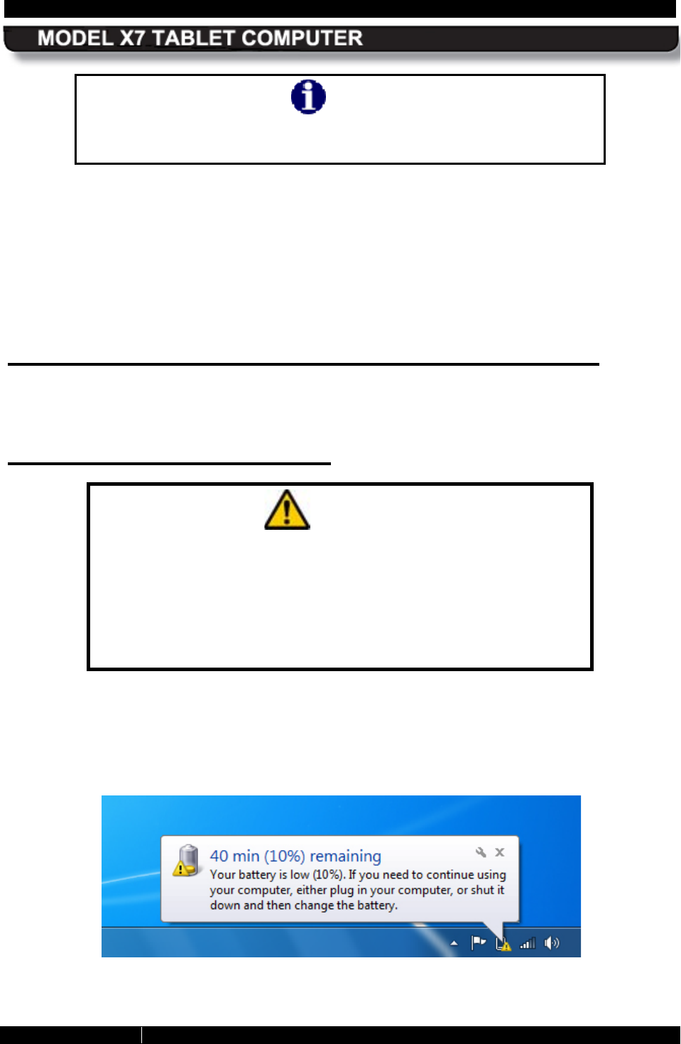
When the total charge drops below 10% (low battery level), a low battery alert message will be
displayed, as shown in Figure 101, and the battery icon in the system application tray (systray)
will display a yellow caution triangle. At this point, DRS recommends you connect external
power to recharge the batteries or replace one or both batteries with fresh batteries.
Figure 101. Low Battery Alert Message
SECTION 9
BATTERY MANAGEMENT
PAGE 196
9711-26400-0001
EXPORT CONTROLLED – SEE PAGE 3
Rev A
R eserved B attery Level Alarm
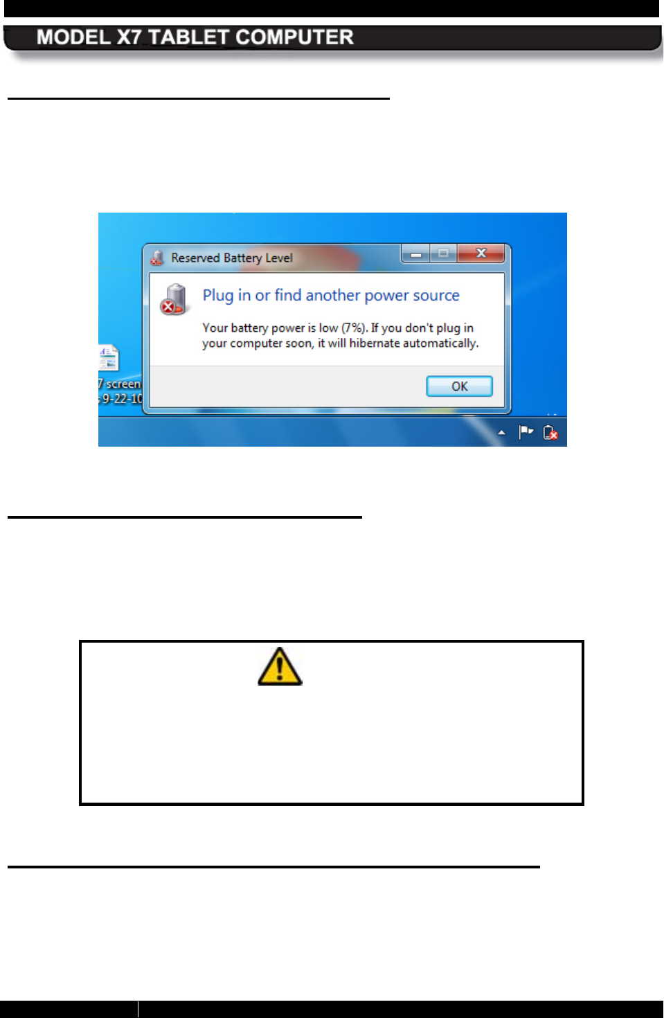
When the remaining charge reaches 7% (reserved battery level), a second battery alert
message will be displayed, as shown in Figure 102, and the battery icon in the task tray will
display a red “X”. At this point, you need to save your work and then connect external power,
replace the batteries or shut down the computer. Otherwise, Windows will automatically force
the computer into hibernation.
Figure 102. Reserved Battery Alert Message
Critical B attery Level Alarm
When the remaining charge reaches 5% (critical battery level), Windows will automatically place
your computer into hibernation mode. Hibernation is a low-power mode that first saves your
current session to storage and then performs an orderly shutdown. You should replace your
depleted batteries or connect external power before restarting your computer.
When you restart your computer, you will resume your session where you left off.
CAUTION!
If the total battery charge drops to 3% or lower while the computer
is operating, the computer can shut down abruptly with the loss of
any work in progress. Normally, the automatic shutdown at the 5%
point will prevent this happening, but heavy demands on the
batteries may cause the battery charge to drop too quickly for the
computer to react and perform a safe shutdown.
What to Do if Y ou G et a L ow B attery Alert
DRS recommends you do one of the following immediately should you get a low battery alert:
• Connect external power and begin recharging the batteries
• Replace one or both of the batteries with a fully charged battery.
• Save your work and perform a normal system shutdown.
SECTION 9
BATTERY MANAGEMENT
PAGE 197
9711-26400-0001
EXPORT CONTROLLED – SEE PAGE 3
Rev A
Fully Depleted (Overly Dis charged) B atteries
If a battery continues to discharge until the total charge reaches the 3% level, it is fully depleted.
At this point, it can usually be recovered (see What to Do for an Overly-Discharged Battery).
However, if the battery continues to discharge, the internal battery circuits may permanently
disable the battery for safety reasons and you will not be able to recover it.
Avoiding Overly-Discharging Your B atteries
The following suggestions will help avoid an overly-discharged condition.
• Recharge your batteries as soon as possible after receiving a low battery alert.
• Do not store the X10gx for long periods with the batteries installed. Even when the unit is
powered off, the tablet still draws a small amount of power from the batteries.
• Do not store X10gx batteries in a fully depleted condition for long periods of time. The
X10gx batteries will further self-discharge over time at a rate of about 10% a month or
3% every 10 days. The batteries should be recharged to 40% of full charge every 3-4
months of storage.
Battery Capacity and Charge
A battery’s “capacity” is it’s ability to deliver a specified amount of energy in the form of electrical
current to the system over a one-hour period, measured in milliamps per hour or mAh. A
battery’s “charge” is the percentage of this capacity that has been restored to the battery. A fully
charged battery is one that can supply 100% of its current maximum capacity.
Maximum Capacity
The maximum capacity of a new battery is very close to its design capacity. However, maximum
capacity gradually decreases over time due to chemical aging, temperature extremes and
usage. Once a battery’s maximum capacity drops below 80% of its designed rating, it is
considered to be at the end of it’s life and is normally replaced. For example, a 4-cell 5900 mAh
hour battery should be replaced when it’s maximum capacity drops below approximately 4720
mAh.
NOTE
While some batteries may still be usable below the minimum
capacity level (<80% of design capacity), the risk for battery failure
and/or unexpected shutdown increases dramatically.
SECTION 9
BATTERY MANAGEMENT
PAGE 198
9711-26400-0001
EXPORT CONTROLLED – SEE PAGE 3
Rev A
Checking your Battery’s Capacity
You can check a battery’s design capacity, maximum capacity and remaining capacity (current
charge level in mAh) by opening ARMORutils and selecting the Battery Monitor option from
the Main window and then selecting either Battery 1 Details or Battery 2 Details (see Battery
Monitor Dialog for a description of these windows).
CAUTION!
Permanent battery capacity loss is greatest at elevated temperatures
with the batteries fully charged. Do not leave batteries installed in
your X7 in high temperature surroundings
with external power
connected for days or weeks at a time.
Remove the batteries and
store them in a cool place.
Discharge/R echarge Cycles
Lithium ion batteries do not need to be deeply discharged periodically to maintain capacity like
certain other types of rechargeable batteries. In fact, deep discharges have a negative effect on
a lithium ion battery’s capacity and operating life.
Each time a lithium ion battery is deeply discharged (<30%) and then recharged (either during
normal operation or conditioning), the battery records the event as a “cycle.” Each of these
deep discharge/recharge cycles has a small cumulative effect on the overall capacity and life of
the battery and (on average) after approximately 300-400 cycles at nominal room temperature,
the battery is a candidate for replacement (sooner if used primarily in high temperatures).
A battery’s accumulated cycles are displayed in the Charge Cycles Count field of each Battery
Information window in ARMORutils (see Figure 60).
How to Optimize B attery Operating Time
You can help ensure the maximum performance of your batteries by optimizing your computer’s
power management features. For some suggested ways to do this, select Start à Control
Panel à Hardware and Sound and click on the Power Options icon.
There are two power plan options: Balanced and High Performance. DRS recommends that
you use the Balanced plan as this provides the optimum battery performance. You can further
customize these plans by clicking on the Change plan settings link.
Monitoring B attery S tatus
You can monitor the status of each battery (current charge level, whether charging or
discharging, etc.) in three ways:
SECTION 9
BATTERY MANAGEMENT
PAGE 199
9711-26400-0001
EXPORT CONTROLLED – SEE PAGE 3
Rev A
1) By clicking on the Battery icon in the systray to open a desktop battery monitor
window. NOTE: The battery icon will change to a battery with plug icon when external
power is connected.
2) By selecting the Battery Monitor Dialog in ARMORutils.
3) By generating an Event Log.
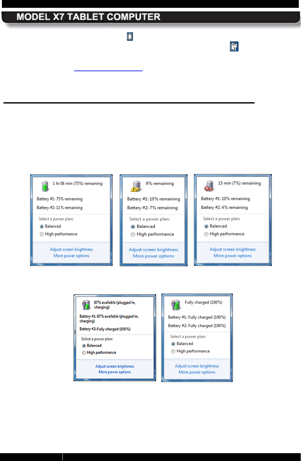
Us ing the Des ktop B attery Monitor Window
Click on the Battery icon in the Windows systray to open the desktop battery monitor window,
Figure 103 shows three examples of the battery window when the X7 is operating on batteries
alone. The example on the far left shows the battery symbol and remaining charge when the
total charge is greater than 10%. The other two examples demonstrate a low battery condition.
Figure 104 shows two examples of the battery symbol and remaining charge when external
power is connected. The left example shows less than full charge and the right example shows
the batteries fully charged.
Figure 103. Windows Desktop Battery Window Examples – Batteries Discharging
Figure 104. Windows Desktop Battery Window Examples – Batteries Charging
SECTION 9
BATTERY MANAGEMENT
PAGE 200
9711-26400-0001
EXPORT CONTROLLED – SEE PAGE 3
Rev A
NOTE
You must restart the Windows desktop battery window to see any
recent changes, such as that resulting from removing a battery or
plugging in external power. To close the window, click outside the
window on the desktop.
Us ing the AR MOR utils B attery Monitor Dialog
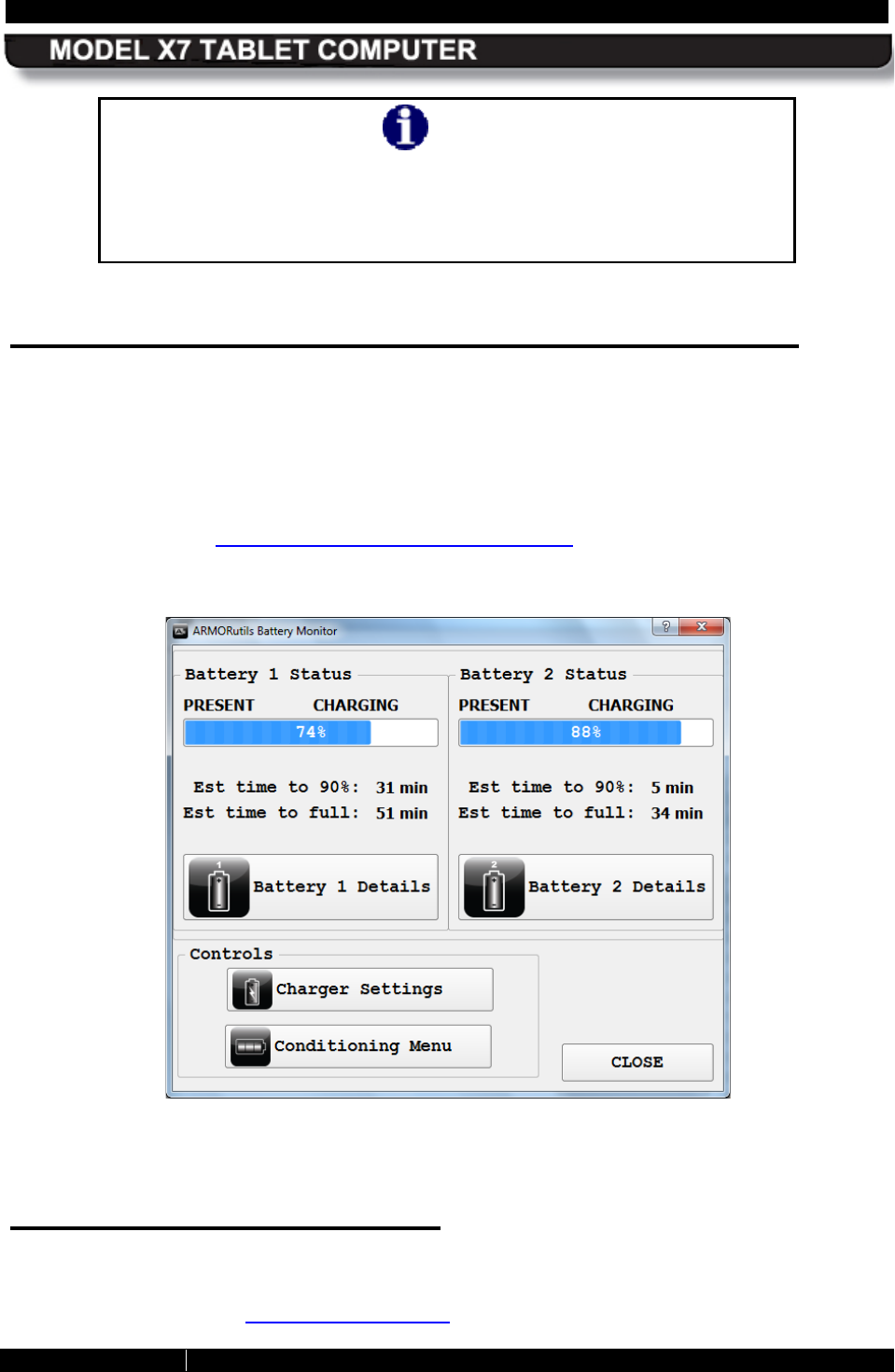
Double-click on the ARMORutils icon on the desktop and select the Battery Monitor button to
open the Battery Monitor dialog window, as shown in Figure 105. This window shows the
current status (charging, discharging, ready) and charge level. It also gives an estimated time to
90% charged and to fully (100%) charged.
For more detailed information about each battery, click on the Battery 1 Details or the Battery
2 Details button to open a Battery Information window with more detailed information about
each battery. Refer to Battery 1 and Battery 2 Details Buttons for a detailed description of these
windows.
Figure 105. ARMORutils Battery Monitor Dialog
Generating an E vent Log
The Event Log is generated from the Event Recorder option on the ARMORutils Diagnostics
dialog. The Event Log allows you to record the changes in system temperatures and battery
status over time. Refer to Creating an Event Log for instructions on using this feature.
SECTION 9
BATTERY MANAGEMENT
PAGE 201
9711-26400-0001
EXPORT CONTROLLED – SEE PAGE 3
Rev A
B attery C onditioning/Calibration
Your ARMOR X7 batteries are self-calibrating and do not normally require the conditioning
process. The only time DRS recommends conditioning/calibrating a battery is if you notice that
the charge levels reported by Windows or ARMORutils, or displayed by the battery gauge, are
consistently different from actual battery performance. This is because conditioning adds to the
charge cycle count of the battery.
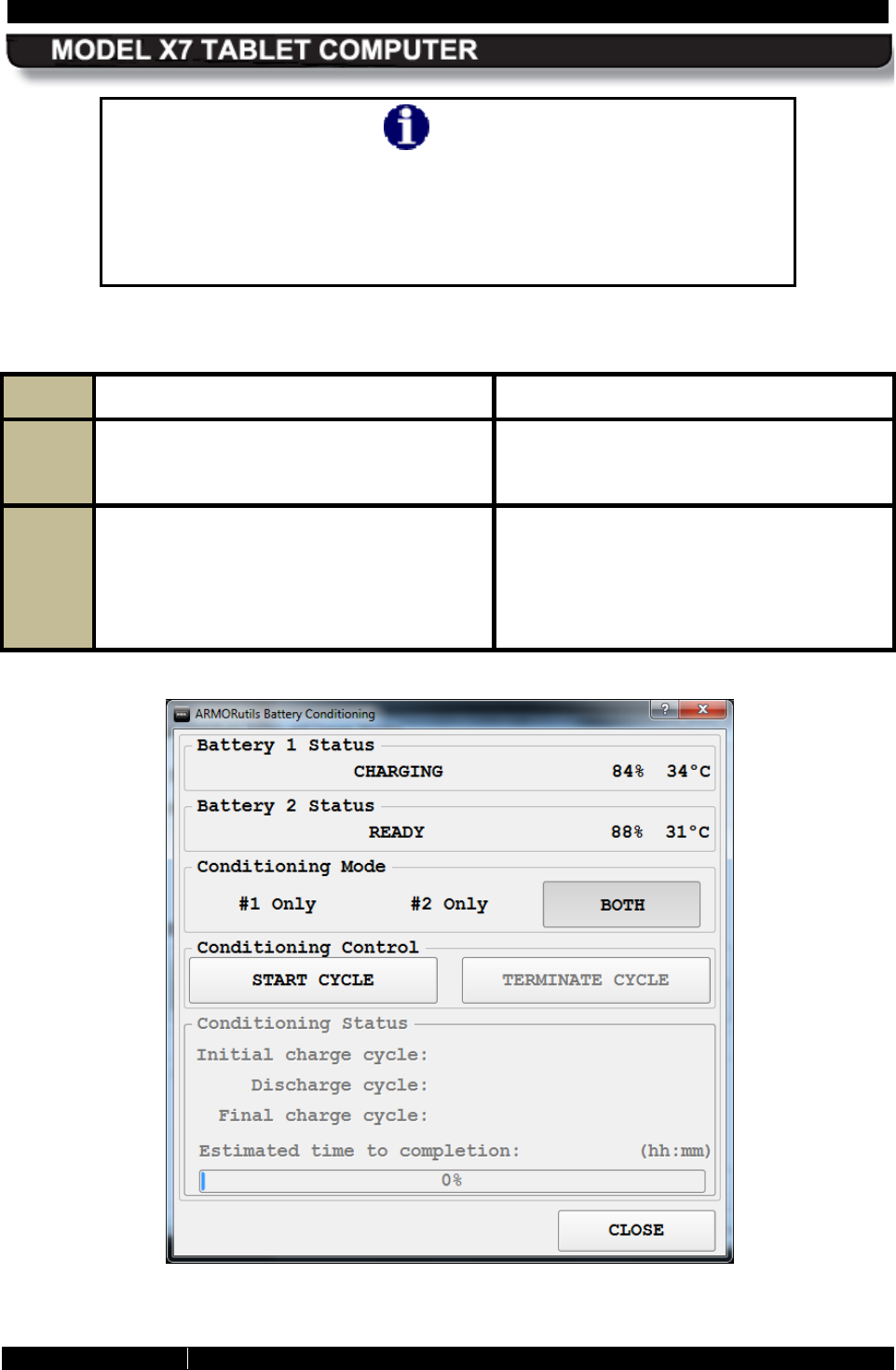
Battery conditioning is a 3-step process consisting of an initial full charge, followed by a full
discharge and finally followed by a full recharge. Each step is documented in the Conditioning
Status panel of the ARMORutils Battery Conditioning window (see Figure 106).
Read the following cautions and notes carefully and follow the procedure in Table 36 to
condition a battery.
CAUTION!
If the internal battery temperature exceeds 45°C or drops below 0°C
during conditioning, the system will abort the conditioning process.
Do not restart conditioning until the internal battery temperature is
well within the above temperature limits to avoid another possible
abort.
CAUTION!
Ensure external power remains connected until conditioning is
complete. If you disconnect externa
l power during the discharge
cycle, conditioning will not abort immediately but will continue until
the battery reaches the 3% charge level, and then abort. If you are
operating on only one battery or the other battery is also low in
charge, you could risk an unexpected shutdown of the tablet.
NOTE
You must have external power connected to condition a battery.
NOTE
The conditioning process can take 3-
5 hours to complete. Ensure
that
external power remains connected for the duration of the
conditioning period.
SECTION 9
BATTERY MANAGEMENT
PAGE 202
9711-26400-0001
EXPORT CONTROLLED – SEE PAGE 3
Rev A
NOTE
Conditioning batteries while the computer is in use can cause
excessive heating inside the X7
. It is recommended that you
decrease the screen brightness as much as possible and close any
unneeded applications during the cond
itioning process to help
reduce heat buildup.
Table 36. Conditioning a Battery
STEP ACTION CONDITION OR INDICATION
1.
Connect external power to the tablet,
either with the included AC adapter or
through a docking station.
2.
Select Start à ARMORutils à Battery
Monitor and click on the Conditioning
Menu button.
The Battery Conditioning window opens,
as shown in Figure 106.
NOTE:
The term “Ready” means the
battery is in a waiting state. It’s next state
may be charging or discharging.
Figure 106. ARMORutils Battery Conditioning Window
SECTION 9
BATTERY MANAGEMENT
PAGE 203
9711-26400-0001
EXPORT CONTROLLED – SEE PAGE 3
Rev A
STEP ACTION CONDITION OR INDICATION
3.
Select #1 Only, #2 Only or Both NOTE:
If only one battery is installed,
selecting that battery will cause the
START CYCLE option to appear in dark
text; if you select the missing battery or
BOTH, the START CYCLE option will
appear in grayed out text.
4.
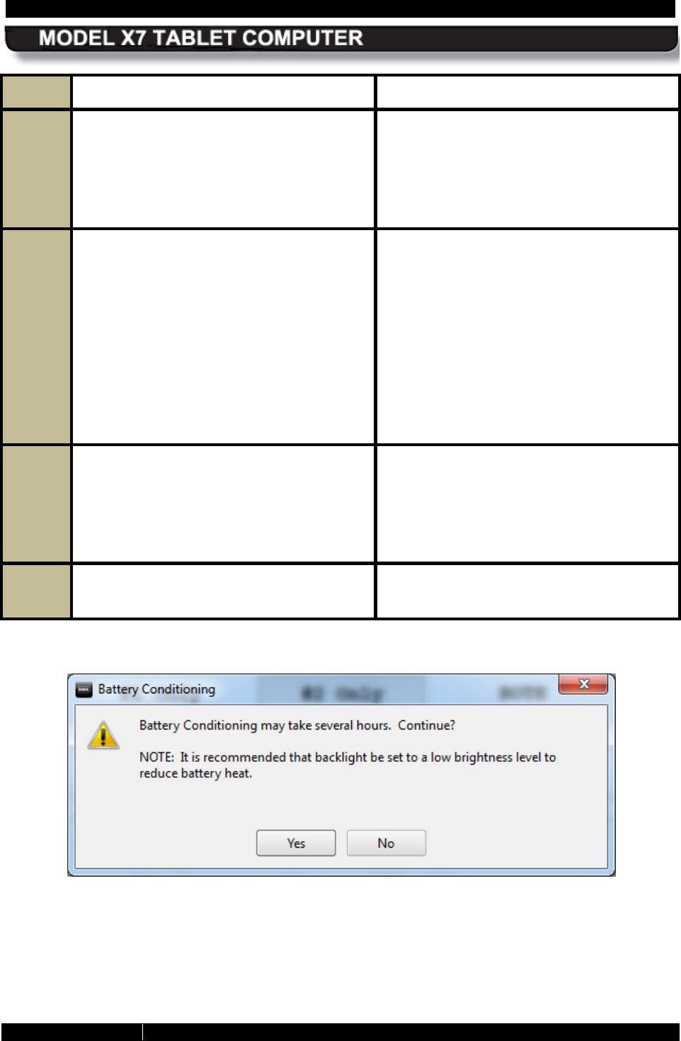
Select START CYCLE. An alert window will appear as shown in
Figure 107.
NOTE: To reduce internal heating during
the conditioning cycle, DRS recommends
you turn down the backlight (brightness)
level as much as practical.
NOTE: If the internal battery temperature
drops below 0°C or exceeds 45°C, the
computer will abort the conditioning
process.
5.
Click on Yes to proceed or No to cancel
the conditioning. The first charge cycle will begin. The
following table lists the approximate
charge times for both the standard and 4-
cell battery.
6.
To terminate the conditioning process at
any time, click on Terminate Cycle.
Figure 107. Battery Conditioning Start Alert Message
SECTION 9
BATTERY MANAGEMENT
PAGE 204
9711-26400-0001
EXPORT CONTROLLED – SEE PAGE 3
Rev A
When to R eplace a B attery
Battery life is affected by the age of the battery, its operating temperature history and the
number of deep discharge/recharge cycles that it goes through over time (see .
Nominal Us age
Industry surveys report that “average daily use” (8 hours or less at nominal room temperature)
equates to approximately 300-400 cycles per year. Batteries operating at this level of usage that
are properly cared for can last as long as two years or even longer. Be advised, however, that a
battery that is more than 2 years old is likely to already be in need of replacement.
Heavy Usage
A battery that is in constant use (24/7), exposed frequently to temperature extremes such as in
a hot vehicle, or is subjected to frequent deep discharging will deteriorate more rapidly. Under
these operating conditions, DRS recommends a battery be replaced after 1 year to prevent a
possible sudden drop in performance.
Determining a B attery’s Age
To determine the age of the battery, check the shipping date on the battery label (see figure
below). This is the date (mm/yy) that the battery was shipped from the manufacturer to DRS.
Figure 108. ARMOR X7 Battery Label
B efore you Dispos e of a B attery
If the battery is less than a year old or has less than 300 cycles, and you find that it consistently
fails to perform as it should, try conditioning the battery before you send it in for warranty
replacement or dispose of it. On rare occasions, an offset can build up between the true battery
charge and what the battery reports. This can lead to the battery’s being charged to a lower
level than what ARMORutils indicates.
To condition a battery, follow the procedure in Battery Conditioning.
SHIPPING
DATE
SECTION 9
BATTERY MANAGEMENT
PAGE 205
9711-26400-0001
EXPORT CONTROLLED – SEE PAGE 3
Rev A
Your B attery’s Warranty
Your X7 battery is warranted by DRS against all defects in material and workmanship for a
period of 1 year from the date of shipment from DRS (not from the date shipped to DRS, as
indicated on the battery label).
Because of the many variables associated with usage and aging, DRS is not responsible for
battery capacity performance except as affected by factory defects or workmanship in the
battery.
Where to Purchase R eplacement B atteries
Your ARMOR X7 uses long lasting Lithium Ion batteries that are custom made for DRS Tactical
Systems, Inc. If you need to purchase replacement batteries, notify your sales representative,
authorized reseller or contact DRS Technical Support.
Do not substitute any other batteries. Substituting non-DRS batteries could damage the X7 and
may void your computer warranty.
How to S tore B atteries When Not in Use
The following storage tips will help you optimize the capacity and performance of your batteries
while in storage.
Short-Term Storage
• If your X7 will powered off for 7-30 days with no external power connected, it is
recommended that the batteries first be fully charged and then removed from the
computer for short-term storage.
• DRS recommends you store your batteries in a cool dry place at room temperature
(25°C/77°F) or below. NOTE: Your batteries can be stored at temperatures up to 35ºC
(95ºF); however, we recommend you not store fully charged batteries at higher
temperatures as this can decrease battery life. Reduce the charge to 30-50% before
storing at temperatures above 32°C (90°F).
• Protect battery contacts from accidentally touching metal objects to avoid a short circuit
and possible arcing or explosion.
• To check a battery’s remaining charge, press the fuel gauge button on the battery or for
a more exact reading, insert it in your X7 and select the Battery Monitor button from the
ARMORutils main window.
Long-T erm S torage
• If your X7 batteries will not be used for 30-90 days or longer, they should be placed in
storage at a temperature below 32°C (90°F), preferably at room temperature
(25°C/77°F) or below to prevent capacity loss.
• Install the batteries in the computer to charge or discharge them to 30-50%.

SECTION 9
BATTERY MANAGEMENT
PAGE 206
9711-26400-0001
EXPORT CONTROLLED – SEE PAGE 3
Rev A
• Protect battery contacts from accidentally touching metal objects to avoid a short circuit
and possible arcing or explosion.
• Lithium ion batteries self discharge at the rate of about 10% per month. While in long-
term storage, you should recharge the batteries every 3-4 months to a charge level of
30-50%.
• To check a battery’s remaining charge, press the fuel gauge button on the battery. For a
more exact reading, insert the battery in your X7 and select the Battery Monitor option
from the ARMORutils main window.
B attery Tips for Best Performance
• Recharge a battery within 24 hours of a full discharge. Batteries remaining in a fully
discharged state longer than 24 hours may deteriorate more quickly.
• Battery charging should be done at temperatures between 32°F (0°C) to 95°F (35°C),
but preferably at room temperature. The battery could deteriorate more quickly when
charged at high temperatures.
• When operating your ARMOR X10gx on external power for extended periods of time (1
week or longer), it’s best to remove the batteries and store them in a cool place until
needed.
• If possible, allow a battery to warm or cool to the temperature of your surroundings
before installing it in the tablet.
SECTION 9
BATTERY MANAGEMENT
PAGE 207
9711-26400-0001
EXPORT CONTROLLED – SEE PAGE 3
Rev A
Dis pos ing of Your Us ed B atteries
Disposal
WARNING!
Disposed lithium-ion batteries that are not fully discharged contain
active salts that can result in an explosion if suddenly exposed to
moisture or water in the environment. To prevent possible injury to
someone finding a discarded
battery, please ensure it is fully
discharged before disposing in a domestic or commercial garbage
receptacle.
You can dispose of your X7 batteries in a normal waste receptacle. However, they contain
recyclable materials that can be extracted and used again. Please see the section on recycling
below.
R ecycling
Lithium-ion batteries are fully recyclable and should not be simply thrown away. Please help
protect our environment by turning in your defective batteries to an authorized recycler, or
sending them back to DRS.
DRS Tactical Systems supports recycling of batteries and will take back your batteries using a
Returned Material Authorization (RMA) form. Please contact the DRS Technical Support center
toll-free at 1-888-872-1100 for more information.
Follow these precautions when handling or returning used batteries:
• Fully discharge the batteries (10% or less).
• Insulate the battery contacts with tape.
• Do not disassemble the batteries.
• Package the batteries so that they cannot move around or make contact with each other.
• Follow the procedure in How to Return a Product to DRS to generate an RMA.

SECTION 9
BATTERY MANAGEMENT
PAGE 208
9711-26400-0001
EXPORT CONTROLLED – SEE PAGE 3
Rev A
This Page Intentionally Left Blank
SECTION 10
TECHNICAL SUPPORT
PAGE 209
9711-26400-0001
EXPORT CONTROLLED – SEE PAGE 3
Rev A
Table of Contents List of Figures List of Tables Acronyms Glossary
10. DR S TECHNICAL SUPPORT
DRS Tactical Systems is committed to providing you best product support and the fastest turn
around service possible.
B efore You C ontact Us
Please have your IT personnel check for network or custom software problems before
contacting DRS Technical Support with a problem.
NOTICE
DRS Tactical Systems, Inc. reserves the right to charge a No Fault
Found (NFF) fee for any unit returned for repair that is found to be
fully operational.
How to R eturn a Product to DR S
Before proceeding, please read Your ARMOR Warranty.
1. Immediately notify DRS.
Inform DRS of your problem at one of the numbers below, or notify an authorized DRS Reseller.
In North America, call: (888) 872-1100 or (321) 309-0599 – 24 hrs, 7 days a week
In the UK, call: 44-(0)-1252-730716
In Europe, call: 49-2246-915-99-77
2. Obtain a Return Merchandise Authorization (RMA) Number.
If it is determined that your product needs to be returned for replacement or repair, a customer
service representative will give you an RMA number. The RMA number is required to return any
product to DRS, regardless of the reason for the return.
3. If you want to use our online RMA service, please ask for a Username and Password.
To access our online RMA service:
1) Go to www.drsarmor.com.
2) Click on the Support tab and select Online RMA.
3) At the login screen, enter your Username and Password.
4) Click on Send.
SECTION 10
TECHNICAL SUPPORT
PAGE 210
9711-26400-0001
EXPORT CONTROLLED – SEE PAGE 3
Rev A
5) Fill out the online form.
6) Print a copy of the form for your records.
7) Select Send.
4. Include the Following Required Information with Your Product(s):
• Company name, address and telephone number.
• RMA number received from DRS (if applicable).
• Serial number of the product (see How to Locate and Interpret your X7 Serial Number).
• Date of purchase.
• Your ship-to address and any special shipping requirements.
• A detailed description of the problem.
5. Prepare your Products for Shipment.
• Back up any important data.
• Remove SIM or SD cards.
• Use the original shipping container if possible to return your product.
• Remove the batteries and package them separately.
• If the original container is not available, wrap each item securely with bubble wrap or
suitable cushioning material.
• Enclose a copy of the RMA form.
• Enclose a description of the problem and any special notes for the repair technician.
6. Ship Your Product(s).
Ship your products to one of the addresses listed below:
NOTE
Transportation and insurance costs must be prepaid
. DRS is not
responsible for loss or damage which may occur in transit.
NOTE
Before you ship any product(s) to DRS, be sure to back up the data on
the X7 storage media.
Remove any confidential, proprietary or
personal information and any removable media such as floppy disks,
CDs or PC Cards. DRS is not responsible for any lost confidential,
proprietary or personal information, removable media or for corrupted
data.
SECTION 10
TECHNICAL SUPPORT
PAGE 211
9711-26400-0001
EXPORT CONTROLLED – SEE PAGE 3
Rev A
In North America, ship to: DRS Tactical Systems, Inc.
1110 West Hibiscus Boulevard
Melbourne, Florida 32901 USA
ATTN: Service
In Europe, ship to: DRS Tactical Systems
Rathausstr. 10
53797 Lohmar, Germany
ATTN: Service Center Technician
Once your product(s) are repaired or replaced under the terms specified in the warranty, DRS
will return your product(s), with shipping pre-paid, to the address included with your RMA.
If You Need Information
Please call us, fax us, email us, or visit our website.
Call us: In North America, call: (888) 872-1100 or (321) 309-0599
In Europe, call: 49-2246-915-99-77
Fax us: In North America: 321-725-0496
In Germany, fax: 49-2246-915-99-78
Email us:
For Support: In North America: support@drs-ts.com
In Europe: sales@drsarmor.eu
For Sales and Information
In North America: Sales@drsarmor.com
In Europe, email: Sales@drsarmor.eu
Or Visit our website at: www.drsarmor.com
For translation in German, click on “Deutsch” at the top of
the page.
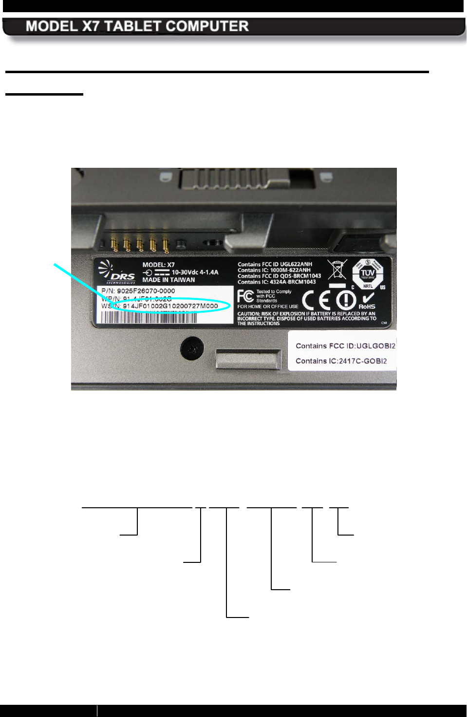
SECTION 10
TECHNICAL SUPPORT
PAGE 212
9711-26400-0001
EXPORT CONTROLLED – SEE PAGE 3
Rev A
How to Locate and Interpret your X7 Serial
Number
Your X7 serial number is printed on a label located inside the left (#1) battery bay, as shown in
Figure 109. It is the 23-digit number beginning with “WS/N” (the “W” in WS/N is a factory code).
This number indicates to DRS the unique configuration of your X7 and its manufacturing history.
Figure 109. ARMOR X7 Unit Label Location
A DRS serial number is broken down as follows:
9 1 4 J F 0 1 0 0 2 G 0 0 2 0 0 7 2 7 M 0 0 0
Year & week manufactured (YWW)
Production code (five digits) (SSSSS)
Manufacturing code (LL)
Engineering version (VV)
Manufacturing assembly
number (PPPPPPPPPP)
Lead-free
WS/N
SECTION 10
TECHNICAL SUPPORT
PAGE 213
9711-26400-0001
EXPORT CONTROLLED – SEE PAGE 3
Rev A
Your AR MOR Warranty
DRS TACTICAL SYSTEMS, INC.
LIMITED WARRANTY – HARDWARE
ARMOR PRODUCTS
General Information
DRS Tactical Systems, Inc. (“DRS”) warrants for the duration of this warranty that the DRS ARMOR product(s) (“Product(s)”)
produced by DRS will be free from defects in material and workmanship under normal use and service, subject to the terms and
conditions set forth herein. This warranty applies to the Products only and excludes, but is not limited to, all other products and
accessories supplied and/or distributed but not manufactured by DRS.
This warranty extends only to the original purchaser of Products from DRS or a DRS Authorized Reseller (“Original Purchaser”). It
is not transferable to anyone who subsequently purchases or obtains the Products from the Original Purchaser.
Length of Warranty
The warranty is valid for a period of three (3) years from the original date of the packing slip from DRS and/or an Authorized
Reseller. During this period, DRS will, at its option and expense, either repair or replace with new or reconditioned (of equal or
better quality) parts of any of the Products which prove to be defective, provided that such Products are returned in accordance with
the terms of this warranty. All exchanged parts and Products replaced under this warranty will become the property of DRS. If
repair or replacement is not feasible, DRS will, at its option, refund the purchase price of the Product(s) on a three year straight line
depreciation basis. Any replacement part or Product will be warranted for the remainder of the original warranty period or ninety (90)
days, whichever is longer.
Terms and Conditions
This warranty covers defects in materials and workmanship in the Products, as follows:
Term 3 years standard
Technical Assistance
Yes
Shipping Costs
Shipping costs of a Product to DRS are not included as part of this Warranty. Shipping
costs of a Product to the Original Purchaser after a warranty repair is included as part of this
warranty. If after receipt of a Product for repair under this warranty, it is later determined to
be a non-warranted repair, all shipping costs are to be paid by the Original Purchaser.
This warranty does not cover:
Non-DRS ARMOR products (accessories) under the original manufacturer’s warranty including, but not limited to, the carrying
case, PCMCIA cards, etc. Non-DRS ARMOR branded products are not covered under an extended warranty period.
Software, including the operating system and software added to the DRS ARMOR hardware products through our factory-
integration system, third-party software, or the reloading of software;
Scratches or abrasions to the Product’s LCD screen/display, and abusive wear of the LCD screens;
Consumables and High Wear Items. Batteries, Keyboards, Touch Pad, Touch Screen, AC Adaptor, and liquid crystal display
(LCD) are covered under the Limited Warranty for one (1) year.
Problems that result from external causes such as accident, fire, floods, or acts of God; abuse; misuse; or problems with
electrical power; servicing not authorized by DRS; failure to follow the Product instructions or failure to perform preventative
maintenance; problems caused by using accessories, parts, or components not supplied by DRS; improper installation (to
include the absence of surge protection in vehicle installations), testing, operation, use or handling of the Product; or
unauthorized alteration of Products
Products with missing or altered service tags or serial numbers.
Products for which DRS has not received payment.
DRS is not responsible for and shall not be liable for transportation and insurance charges incurred in or damages resulting
from transporting the Products, Accessories and/or Replacement Products to DRS for warranty service.

SECTION 10
TECHNICAL SUPPORT
PAGE 214
9711-26400-0001
EXPORT CONTROLLED – SEE PAGE 3
Rev A
DRS is not responsible for any third-party software created for use in the integration and/or operation of any Products,
Accessories and/or Replacement Products whether or not such third party software was installed by DRS. Maintenance and
support service for third-party software is the sole responsibility of the creator thereof.
Additional Information
The agents, dealers, DRS Authorized Resellers and employees of DRS are not authorized to make any modifications to this
warranty, or additional warranties binding on DRS about or for Products, Accessories and/or products sold or supplied by DRS.
Additional statements, whether oral or written, except signed written statements from an officer of DRS, do not constitute warranties
and should not be relied upon.
The Product is not designed or certified for use in high risk applications including, but not limited to, the operation of nuclear
facilities, aircraft navigation or air traffic control systems, communications systems in which a failure thereof could cause death or
serious injury or property damage (e.g., emergency or 911 communications systems), medical systems, life support, weapons
systems or any other potentially life critical uses. Original Purchaser understands and agrees that DRS makes no assurances or
warranties that the Product is suitable for any such high risk uses.
DRS’ SOLE LIABILITY, AND ORIGINAL PURCHASER’S SOLE REMEDY, FOR ANY MALFUNCTIONS AND DEFECTS IN THE
PRODUCTS IS LIMITED TO REPAIR AND REPLACEMENT AS SET FORTH IN THIS WARRANTY STATEMENT. EXCEPT AS
OTHERWISE EXPRESSLY STATED HEREIN, DRS DISCLAIMS ALL OTHER WARRANTES, WHETHER EXPRESS OR IMPLIED,
INCLUDING BUT NOT LIMITED TO ANY IMPLIED WARRANTIES OF MERCHANTABILITY AND FITNESS FOR A PARTICULAR
PURPOSE, AND ANY IMPLIED WARRANTIES OTHERWISE ARISING FROM COURSE OF DEALING OR TRADE. NO
WARRANTIES WILL APPLY AFTER THE WARRANTY PERIOD HAS EXPIRED.
DRS HEREBY DISCLAIMS, AND THE ORIGINAL PURCHASER HEREBY AGREES, THAT DRS DOES NOT ACCEPT LIABILITY
BEYOND THE REMEDIES PROVIDED FOR IN THIS WARRANTY OR FOR ANY INDIRECT, CONSEQUENTIAL, PUNITIVE,
SPECIAL, OR INCIDENTAL DAMAGES, INCLUDING, WITHOUT LIMITATION, ANY LIABILITY FOR THIRD PARTY CLAIMS FOR
DAMAGES, FOR PRODUCTS NOT BEING AVAILABLE FOR USE, OR FOR LOST DATA OR LOST SOFTWARE.
NOTWITHSTANDING ANYTHING CONTAINED HEREIN, DRS’ TOTAL LIABILITY FOR ANY ALLEGED OR ACTUAL BREACH OF
WARRANTY WILL BE NO MORE THAN THE AMOUNT PAID FOR THE PRODUCT THAT IS THE SUBJECT OF ANY SUCH
CLAIM. THIS IS THE MAXIMUM AMOUNT FOR WHICH DRS SHALL BE RESPONSIBLE.

REAR MATTER PAGE 215
9711-26400-0001
EXPORT CONTROLLED – SEE PAGE 3
Rev -
Table of Contents List of Figures List of Tables Glossary
AC R ONYMS
ACRONYM DEFINITION
AC
alternating current
BIOS basic input/output system
CD-ROM compact disk – read only memory
CDMA
code division multiple access
CPU central processing unit
DC
direct current
DVD digital video disk
EDGE enhanced data rates for GSM evolution
EVDO
evolution data only/evolution data optimized
GB gigabytes
GPRS
general packet radio service
GPS global positioning system
GSM global system for mobile communications
HSDPA
high-speed downlink packet access
I/O Input/Output
LCD liquid-crystal display
LED light-emitting diode
OEM original equipment manufacturer
NDIS
network driver interface specification
PC personal computer
PCMCIA personal computer memory card international association
RAM random access memory
SD secure digital
SDHC
secure digital high capacity
SIM subscriber identity module
SmBus system management bus
SODIMM small outline dual in-line memory module
SVGA super VGA (maximum of 800 x600 pixels)
TFT
thin-film transistor
USB universal serial bus
VAC volts AC
VDC volts DC
VGA video graphics array
WLAN
wireless local area network
WWAN wireless wide area network
XGA extended VGA (1024 x 768 pixels)

REAR MATTER PAGE 216
9711-26400-0001
EXPORT CONTROLLED – SEE PAGE 3
Rev A
GLOSSARY
TERM DEFINITION
ambient temperature The temperature of the air surrounding an object
depleted battery
A lithium-ion battery that has discharged to a level between 10%
and 3% of charge, as indicated by a flashing 10% LED on the
Battery Gauge.
fully charged battery
A lithium-ion battery that has reached 100% of charge as indicated
by a steady 100% LED on the Battery Gauge.
fully depleted battery
A lithium-ion battery that has discharged to a level of 3 % or below.
fully discharged battery
Same as depleted.
flexspace A special compartment with a flexible communications interface for
custom circuit cards or modules.
overly discharged battery
A fully depleted battery that has discharged to the point where it will
not respond to normal efforts to recharge it and is in danger of
becoming unrecoverable.
storage device
Any fixed or removable storage device (mSATA, SD card, flash
drive
) that the processing system can use for temporary or
permanent data storage.
systray
System application tray. A small area of the Windows task bar that
displays icons of applications and utilities that remain running in the
background.
REAR MATTER PAGE 217
9711-26400-0001
EXPORT CONTROLLED – SEE PAGE 3
Rev A
Table of Contents List of Figures List of Tables Acronyms Glossary
APPENDIX A
Explanation of Active Pen S ide B utton
Options
4th Click (Back) Duplicates a 4th mouse button click – usually the Back command in
browser application.
5th Click (Forward) Duplicates a 5th mouse button click –
usually the Forward
command in browser application.
Click Duplicates a left mouse button click.
Click Lock Duplicates holding an object with the left mouse button; good for
dragging objects or selecting text or groups of objects. Press
button to grab, press to release.
Default Sets the switch function to Right Click
Disabled Disables the side switch.
Double Click Generates a double-click action with a single press of the side
switch.
Erase Enables the pen tip to act like an eraser in handwriting applications
and in some paint and imaging editing programs.
Journal Opens Microsoft Journal™ (only with versions of Windows that
include Microsoft Journal).
Keystroke… Enables you to define special keystrokes. This function can also be
made available using the Pop-up Menu option (must be defined in
the Pop-up Menu tab of the Pen Computer Properties dialog.
Middle Click Duplicates pressing the middle scroll button on a mouse.
Mode Toggle… Toggles between Pen and Mouse mode if pre-configured in the
Pop-Up Menu tab of the Pen Computer
Properties dialog (see
Windows Control Panel).
Modifier… Enables you to duplicate a shift, ctrl, alt or click function.
Open/Run… Opens or runs a pre-selected application. This function can also be
made available using the Pop-up Menu option.
Pan/Scroll… Enables you to use the pen like a hand to move a document or
image in any direction within an active window.
Pop-up Menu Makes available selections enabled in the Pop-up Menu tab of the
Pen Computer Properties dialog (see Windows Control Panel).
Pressure Hold Primarily used with painting programs to maintain the pressure of a
brush stroke.
Right Click Duplicates a right mouse button click.

REAR MATTER PAGE 218
9711-26400-0001
EXPORT CONTROLLED – SEE PAGE 3
Rev A
Computer PC Defined Uses the pen settings defined in the Pen Options tab of the Pen
and Touch dialog window.
Computer PC Input Panel
Opens the Computer PC input panel (only with versions of
Windows that support Computer PC).
REAR MATTER PAGE 219
9711-26020-0001 Export Controlled – See Page 3 Rev -
Table of Contents List of Figures List of Tables Acronyms Glossary
APPENDIX B
Using the X7 External B attery Charger
Step Action Comment
1.
Hold the battery with its connector
pointing down and the rounded edge of
the battery facing away from the
charger, as shown in Figure 110.
2. Insert the battery into the bay and gently
press down to engage the locking
latches. Rock the battery slightly to
ensure the battery is locked in place.
The battery button will snap into place
when the latch is engaged. The charging
will begin immediately, as indicated by
the steady yellow charge indicator.
When charging is complete, the yellow
LED will turn off and the green (fully
charged) LED will turn on.
3.
To remove the battery, press on the
spring-
loaded battery release button
and lift the battery from the charging
bay.
Figure 110. Inserting a Battery into the Battery Charger
REAR MATTER PAGE 220
9711-26400-0001
EXPORT CONTROLLED – SEE PAGE 3
Rev A
Charger LE D Status Indications
There are two status indicators for each battery bay. The table below lists the possible indicator
conditions and their meanings.
Status Indicator Condition
Fully Charged Battery LED (green) On steady with external power applied
and battery fully charged (>95%).
Flashing (2 sec on / 1 sec off) when
battery near full charge (85% - 95%)
Off with external power disconnected or
battery charge less than 85%.
Charging LED (amber) On steady with external power applied,
temperature in limits and battery
charging.
Flashing (1 sec on/1 sec off) with
external power applied, temperature in
limits and other battery is currently
charging (hybrid charging).
Off when battery is not charging.
Fault LED (red) On steady when fault in power system
is detected (over voltage, under voltage,
excessive current, charger circuit failure
or battery circuit failure).
Flashing (1 sec on/1 sec off) with
external power applied and battery
temp above or below max limits.
Off when fault is corrected.
REAR MATTER PAGE 222
9711-26400-0001
EXPORT CONTROLLED – SEE PAGE 3
Rev A
REAR MATTER PAGE 223
9711-26400-0001
EXPORT CONTROLLED – SEE PAGE 3
Rev A
REAR MATTER PAGE 224
9711-26400-0001
EXPORT CONTROLLED – SEE PAGE 3
Rev A
REAR MATTER PAGE 225
9711-26400-0001
EXPORT CONTROLLED – SEE PAGE 3
Rev A
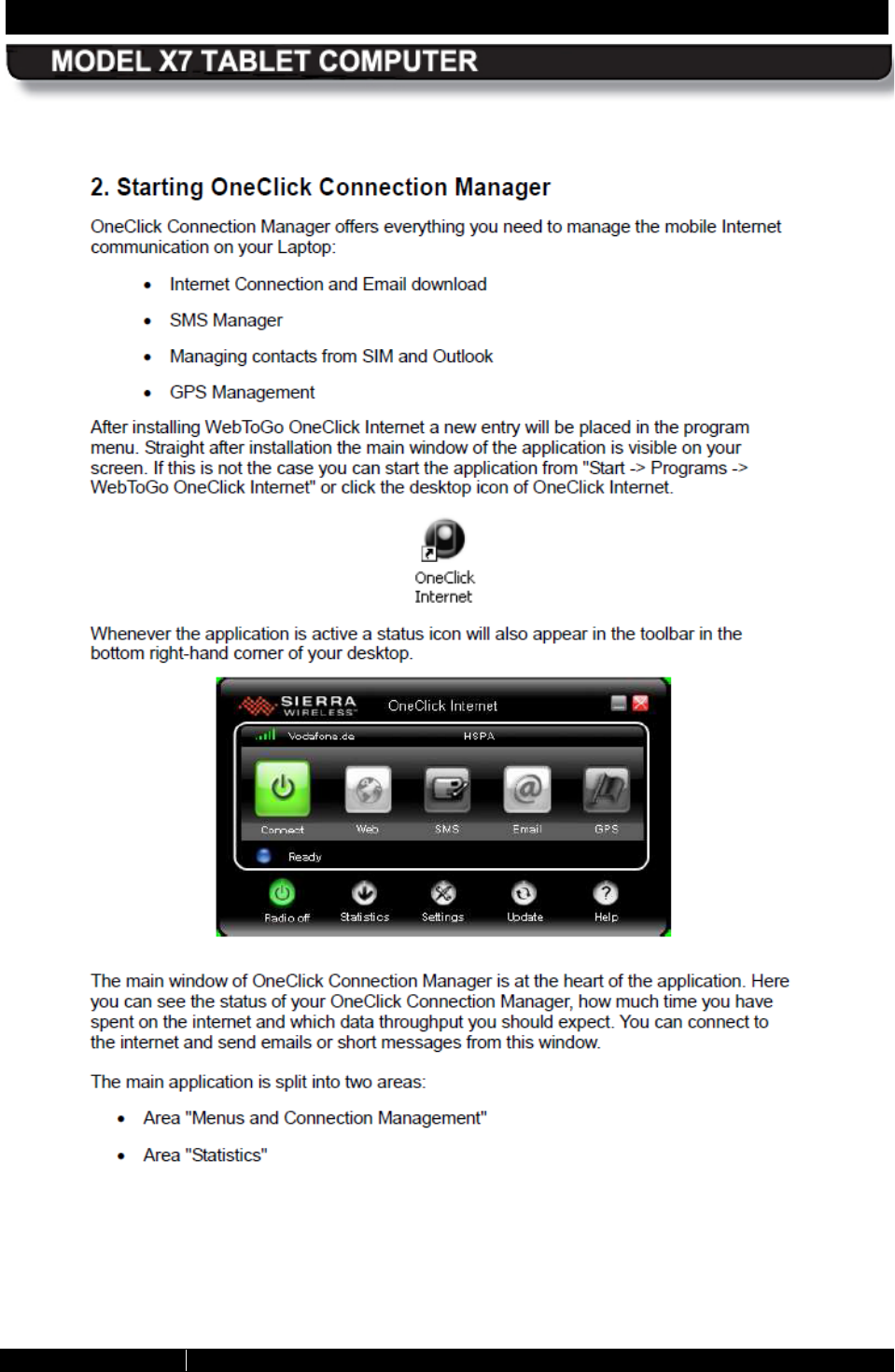
REAR MATTER PAGE 226
9711-26400-0001
EXPORT CONTROLLED – SEE PAGE 3
Rev A
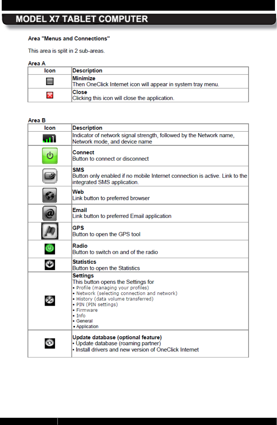
REAR MATTER PAGE 227
9711-26400-0001
EXPORT CONTROLLED – SEE PAGE 3
Rev A
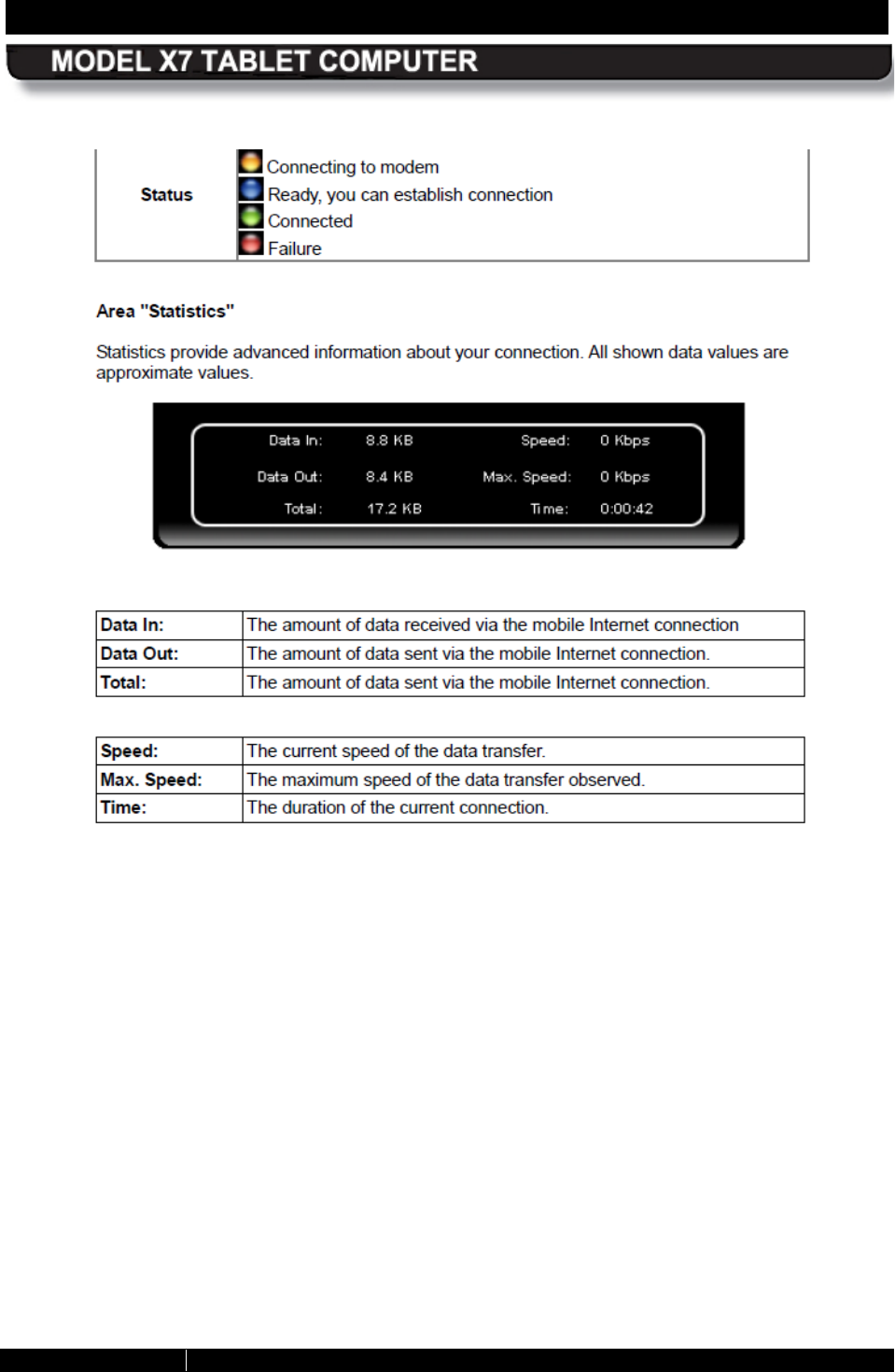
REAR MATTER PAGE 228
9711-26400-0001
EXPORT CONTROLLED – SEE PAGE 3
Rev A
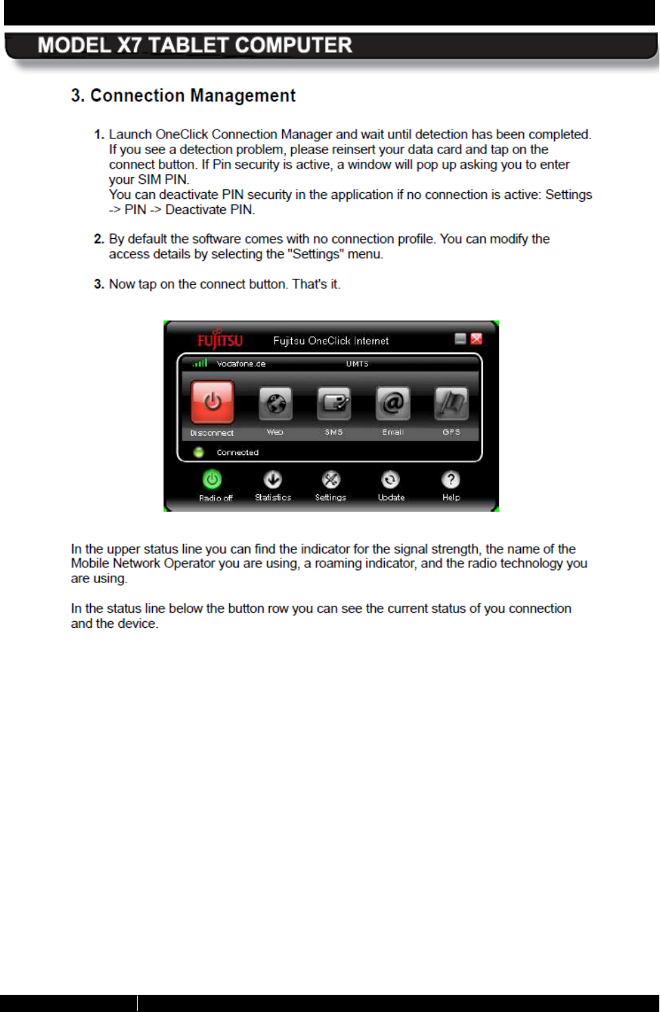
REAR MATTER PAGE 229
9711-26400-0001
EXPORT CONTROLLED – SEE PAGE 3
Rev A
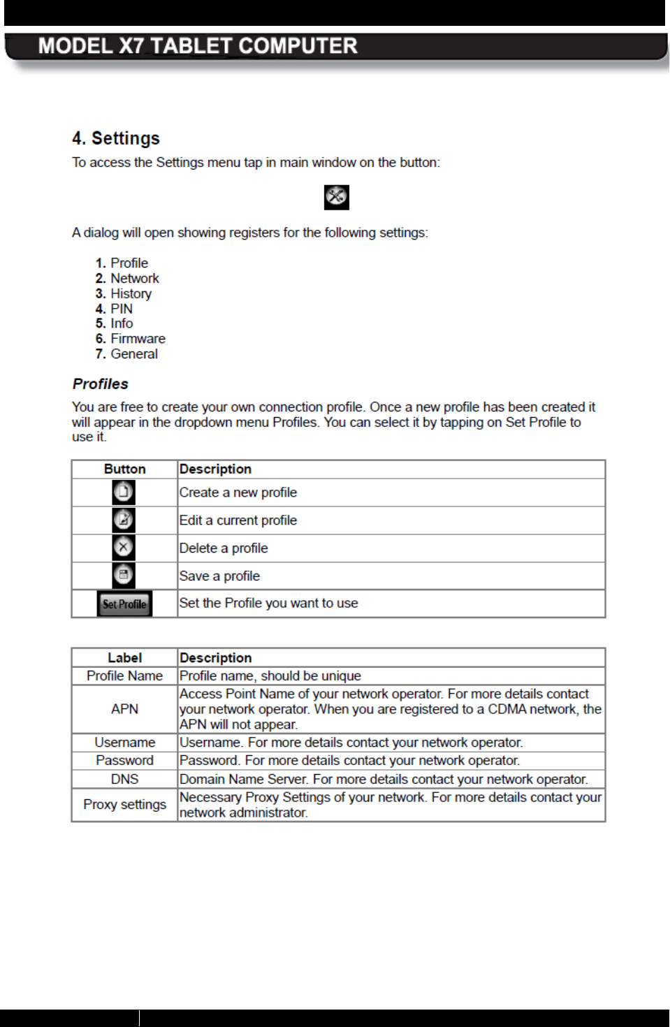
REAR MATTER PAGE 230
9711-26400-0001
EXPORT CONTROLLED – SEE PAGE 3
Rev A
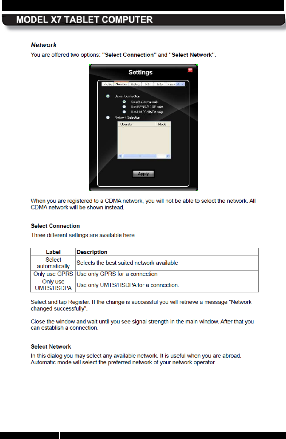
REAR MATTER PAGE 231
9711-26400-0001
EXPORT CONTROLLED – SEE PAGE 3
Rev A
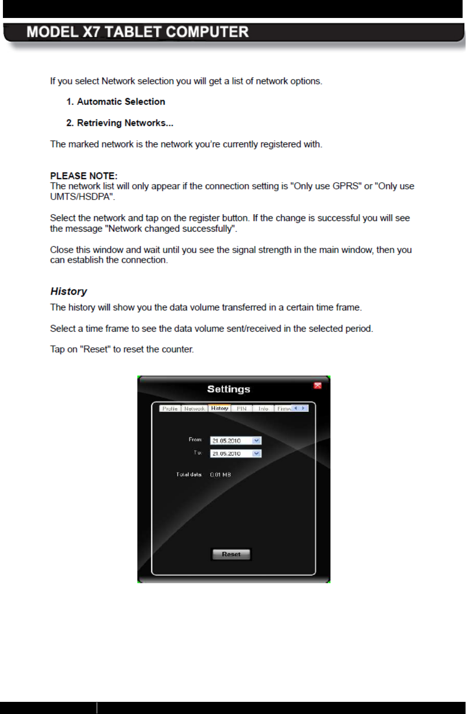
REAR MATTER PAGE 232
9711-26400-0001
EXPORT CONTROLLED – SEE PAGE 3
Rev A

REAR MATTER PAGE 233
9711-26400-0001
EXPORT CONTROLLED – SEE PAGE 3
Rev A
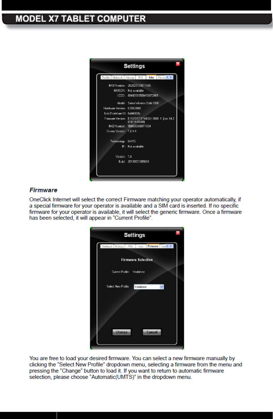
REAR MATTER PAGE 234
9711-26400-0001
EXPORT CONTROLLED – SEE PAGE 3
Rev A
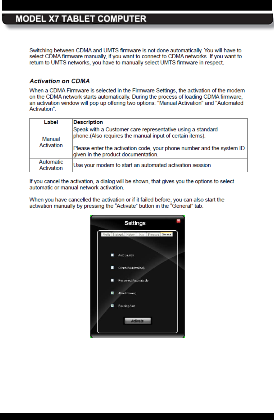
REAR MATTER PAGE 235
9711-26400-0001
EXPORT CONTROLLED – SEE PAGE 3
Rev A
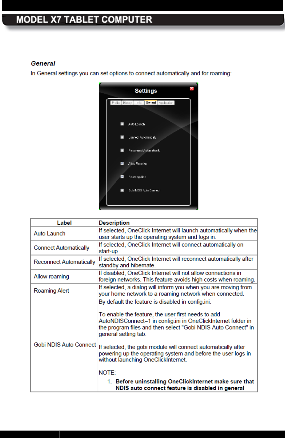
REAR MATTER PAGE 236
9711-26400-0001
EXPORT CONTROLLED – SEE PAGE 3
Rev A
REAR MATTER PAGE 237
9711-26400-0001
EXPORT CONTROLLED – SEE PAGE 3
Rev A
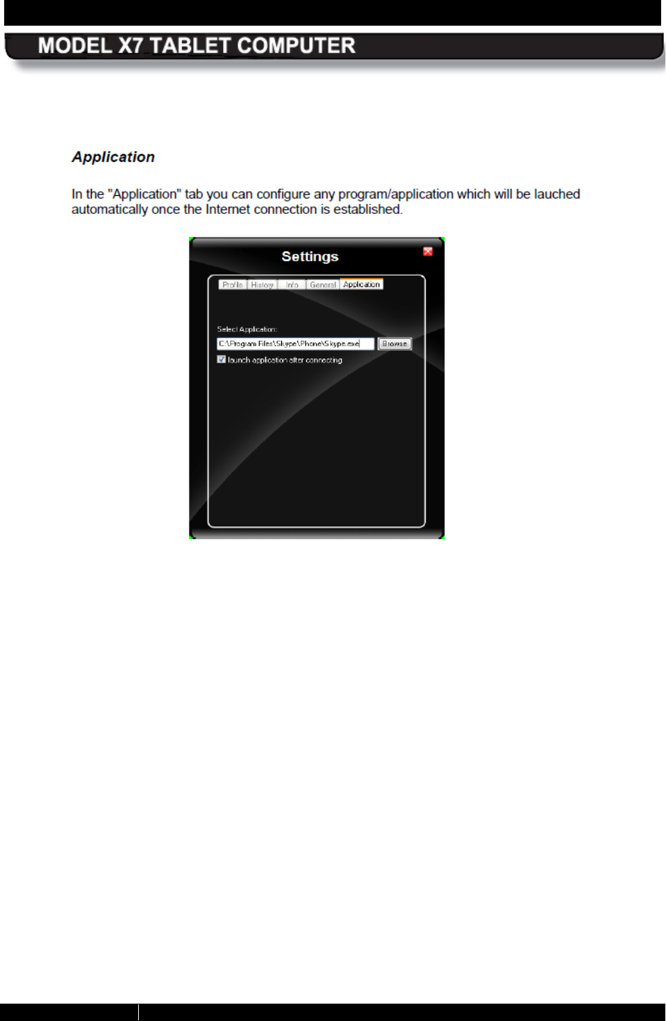
REAR MATTER PAGE 238
9711-26400-0001
EXPORT CONTROLLED – SEE PAGE 3
Rev A
REAR MATTER PAGE 239
9711-26400-0001
EXPORT CONTROLLED – SEE PAGE 3
Rev A
REAR MATTER PAGE 240
9711-26400-0001
EXPORT CONTROLLED – SEE PAGE 3
Rev A
REAR MATTER PAGE 241
9711-26400-0001
EXPORT CONTROLLED – SEE PAGE 3
Rev A
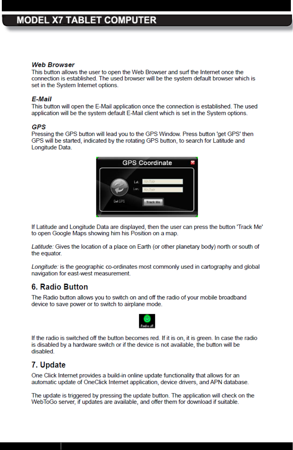
REAR MATTER PAGE 242
9711-26400-0001
EXPORT CONTROLLED – SEE PAGE 3
Rev A
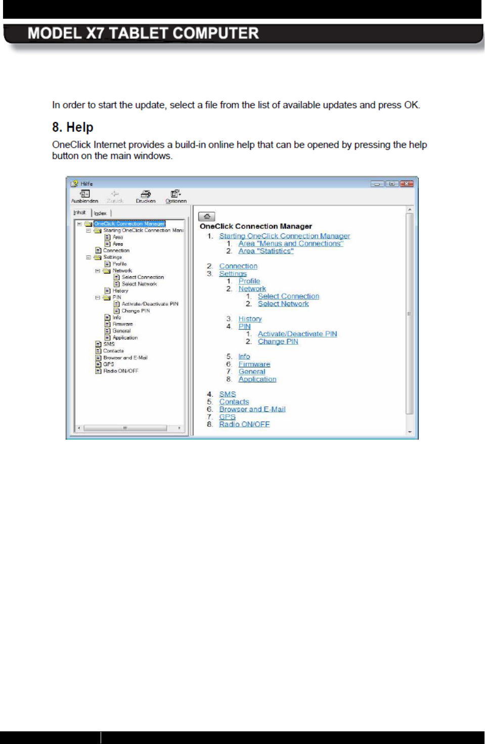
REAR MATTER PAGE 243
9711-26400-0001
EXPORT CONTROLLED – SEE PAGE 3
Rev A

REAR MATTER PAGE 244
9711-26400-0001
EXPORT CONTROLLED – SEE PAGE 3
Rev A
This Page Intentionally Left Blank
REAR MATTER PAGE 245
9711-26400-0001
EXPORT CONTROLLED – SEE PAGE 3
Rev A
RECORD OF CHANGES
Rev ECO # Description Of Change
- 84062 Initial Release.
A 84890 Manual extensively revised.
REAR MATTER PAGE 246
9711-26400-0001
EXPORT CONTROLLED – SEE PAGE 3
Rev A
This Page Intentionally Left Blank