DRS Tactical Systems 633ANH Intel Centrino Ultimate-N 6300 User Manual FCC Part 15
DRS Tactical Systems, Inc. Intel Centrino Ultimate-N 6300 FCC Part 15
UserManual.wiki
>
DRS Tactical Systems
>
633ANH User Manual
Manual
Navigation menu
Upload a User Manual
Namespaces
Wiki Guide
HTML
PDF
Info
Views
User Manual
Discussion / Help
Navigation

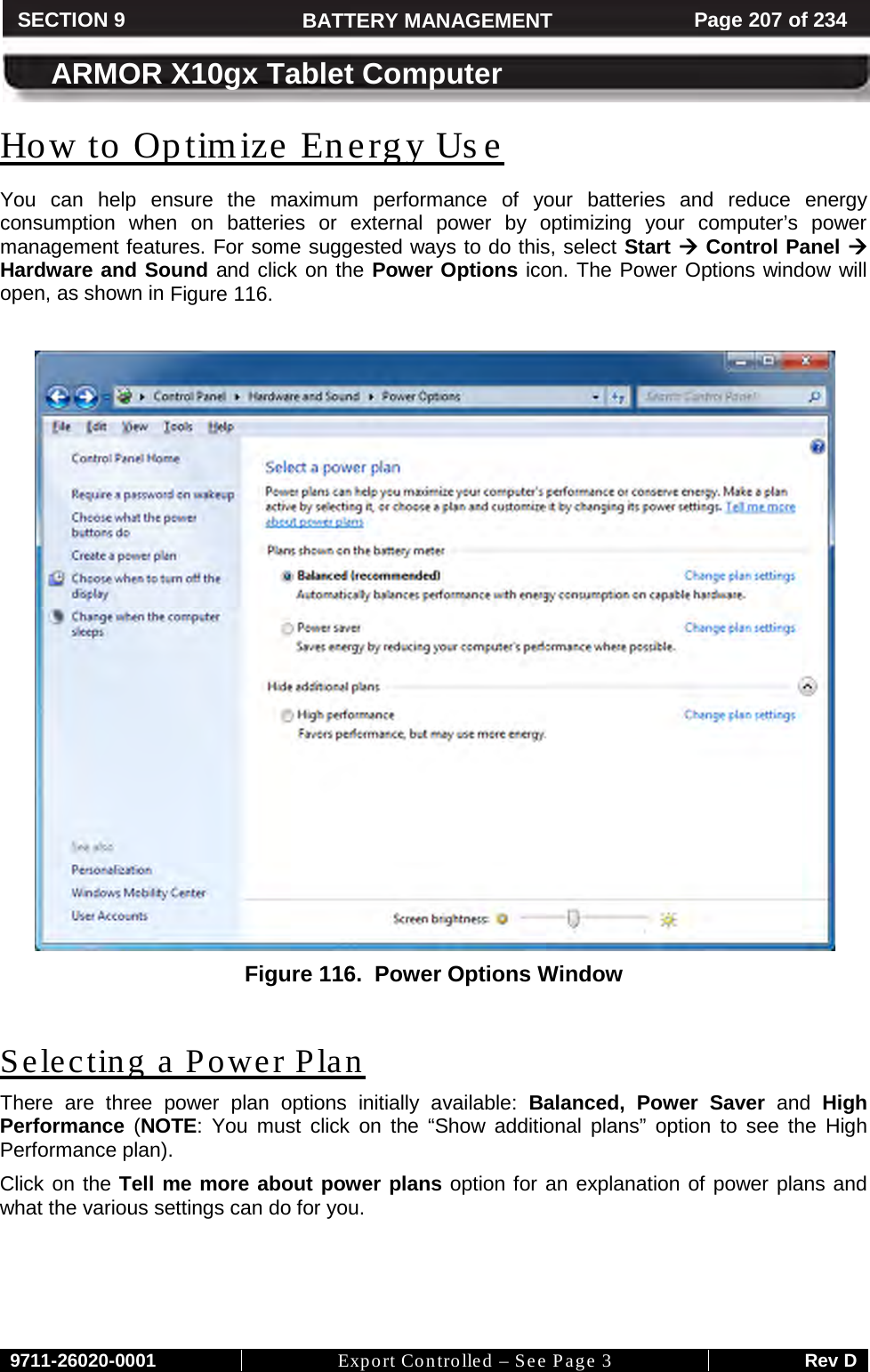
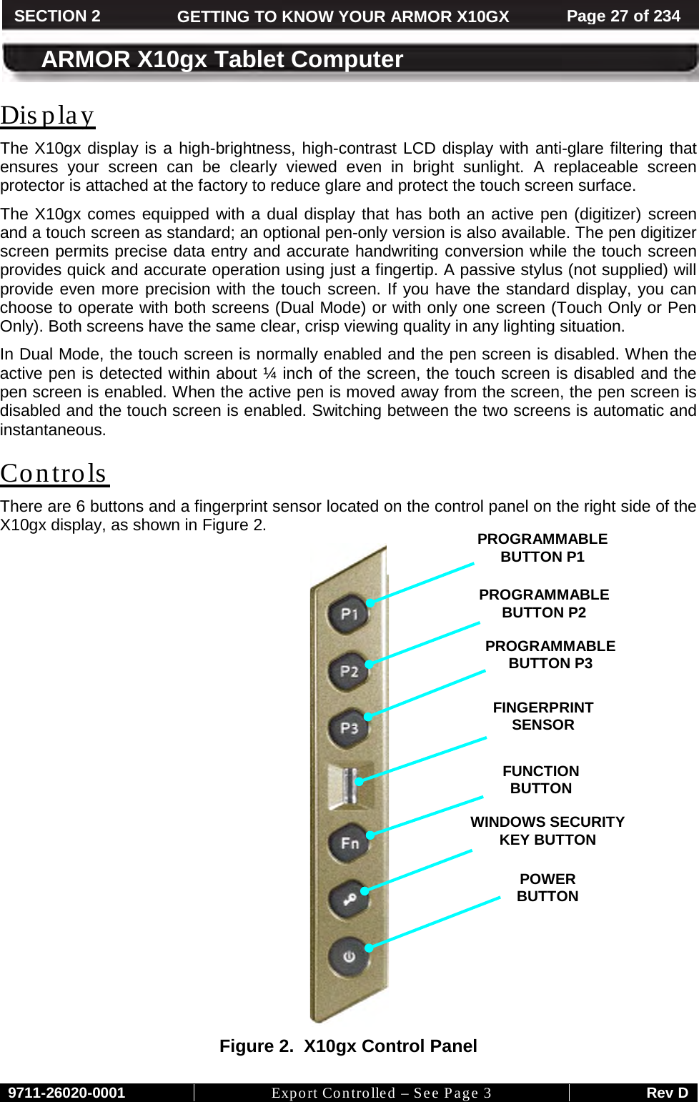
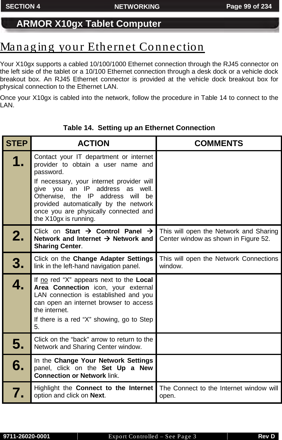
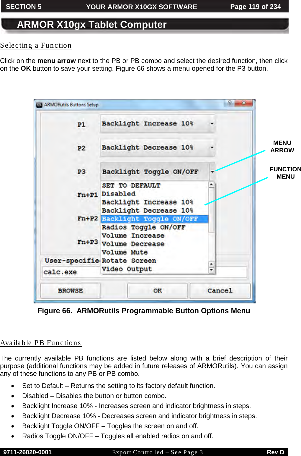
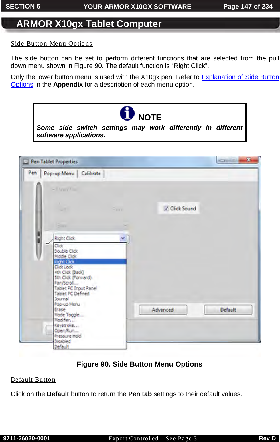
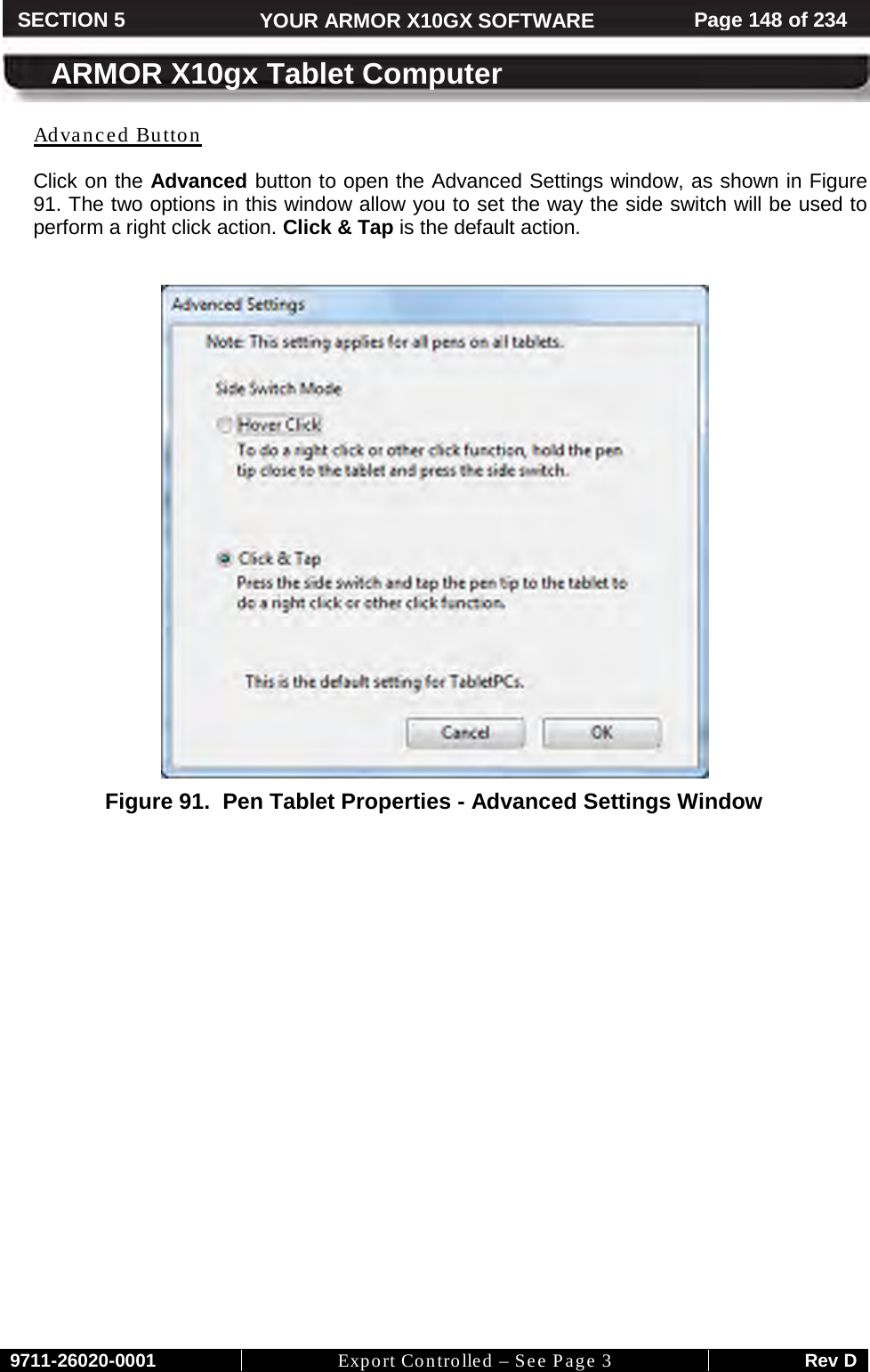
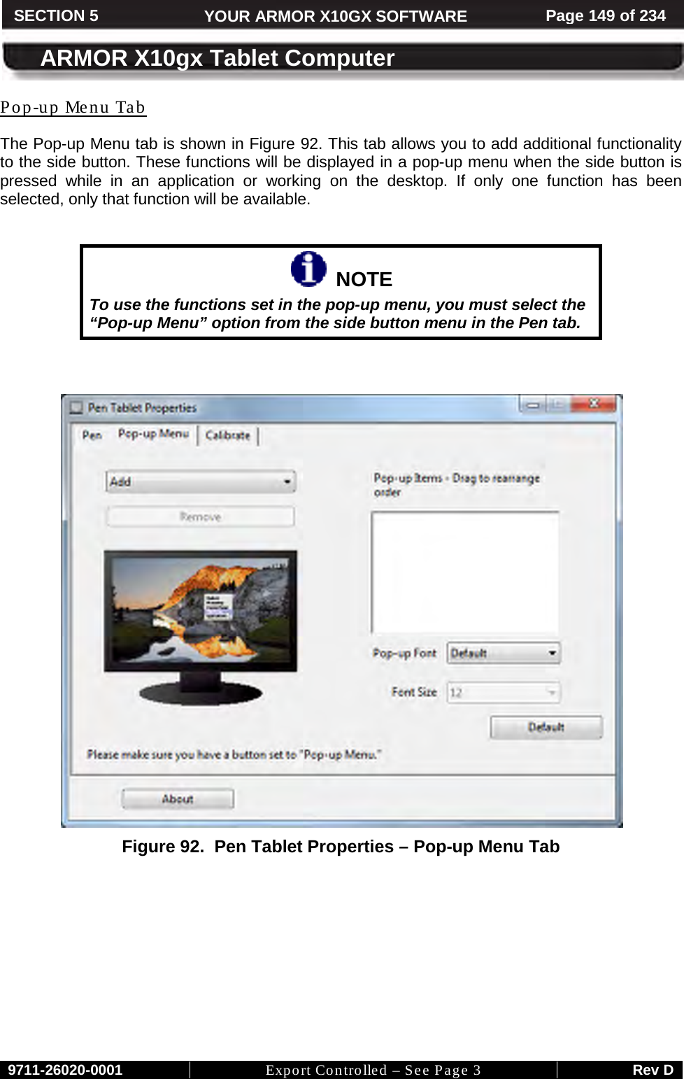
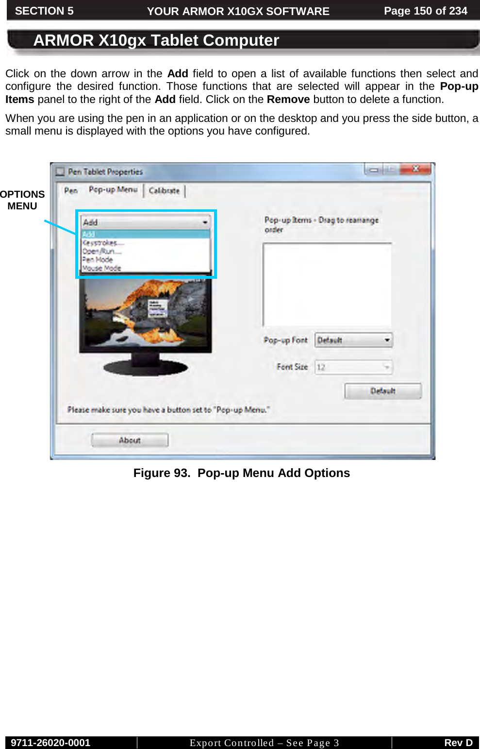
![9711-26020-0001 Export Controlled – See Page 3 Rev D FRONT MATTER CONTENT Page 11 of 234 ARMOR X10gx Tablet Computer CAUTION! Recharging batteries must only be carried out in a non-hazardous area using the supplied AC adapter. The definition of hazardous areas can be found in Standard EN 60079-10. CAUTION! DO NOT use this unit in classified areas unsuitable for its safety ratings. NE PAS UTILISER CETTE UNITÉ EN ZONES AINSI CLASSÉES IMPROPRES À SA COTE DE SÉCURITÉ CAUTION! When using IEEE 802.11a wireless LAN [in Canada], this product is restricted to indoor use due to its operation in the 5.15- to 5.25-GHz frequency range. Industry Canada requires this product to be used indoors for the frequency range of 5.15 GHz to 5.25 GHz to reduce the potential for harmful interference to co-channel mobile satellite systems. High power radar is allocated as the primary user of the 5.25- to 5.35-GHz and 5.65 to 5.85-GHz bands. These radar stations can cause interference with and/or damage to this device.](https://usermanual.wiki/DRS-Tactical-Systems/633ANH/User-Guide-1497857-Page-12.png)
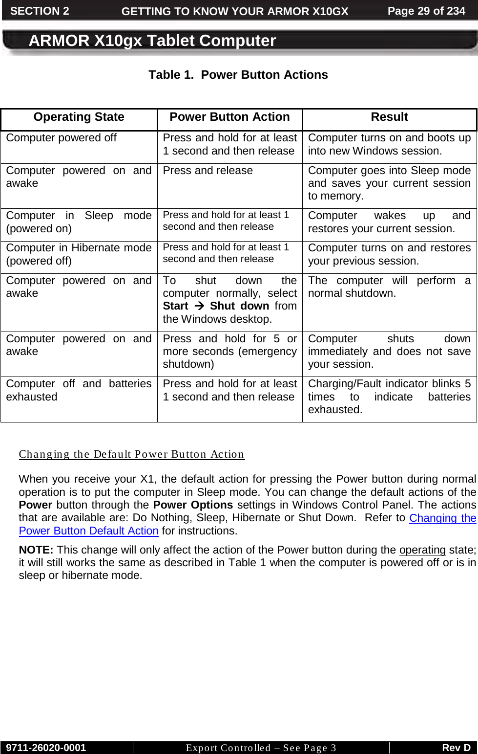
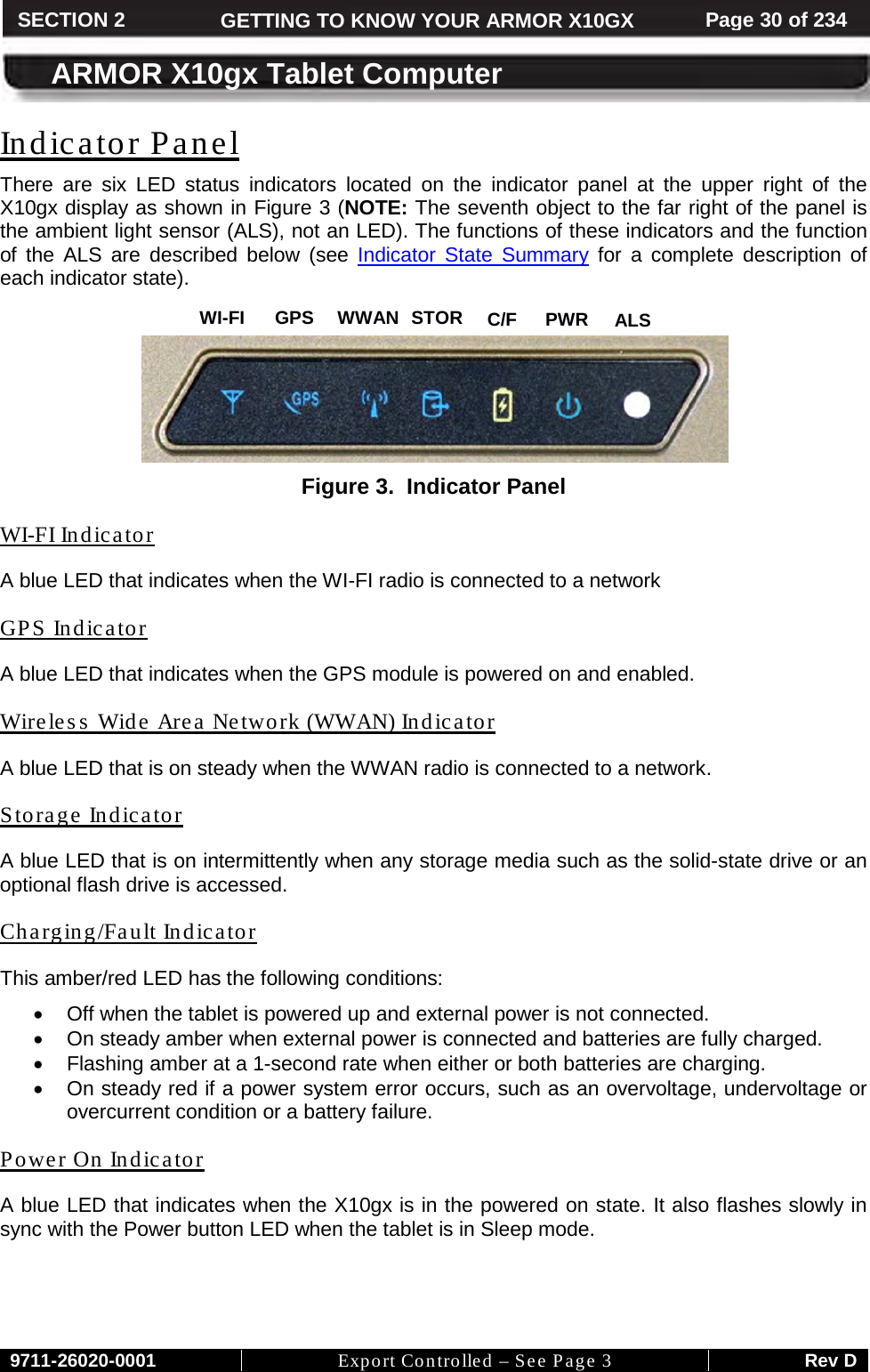
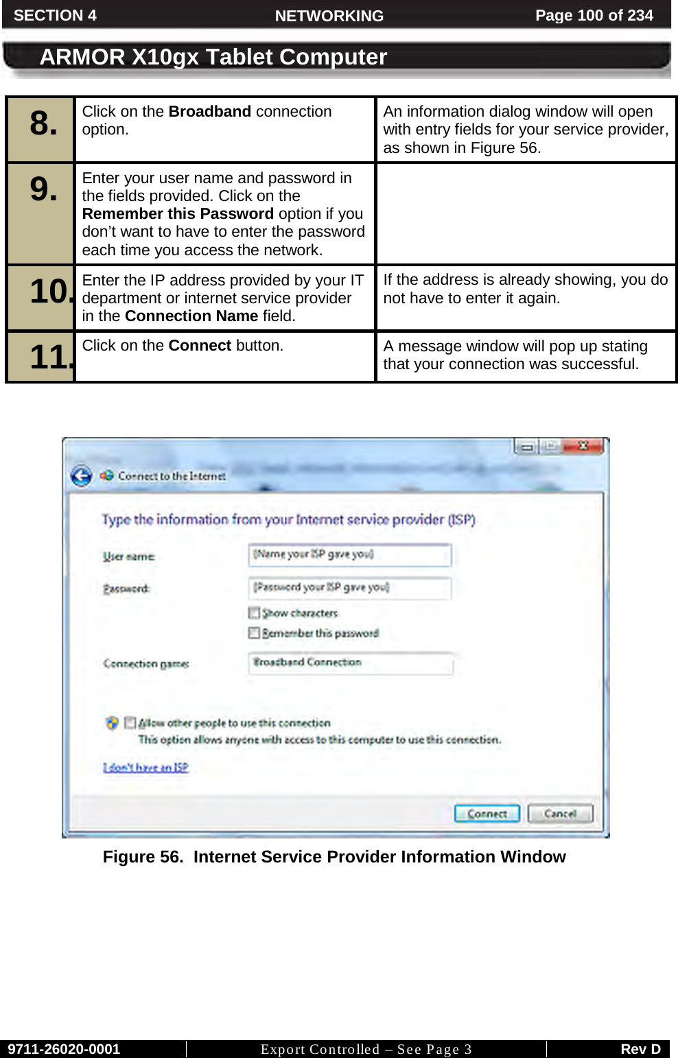
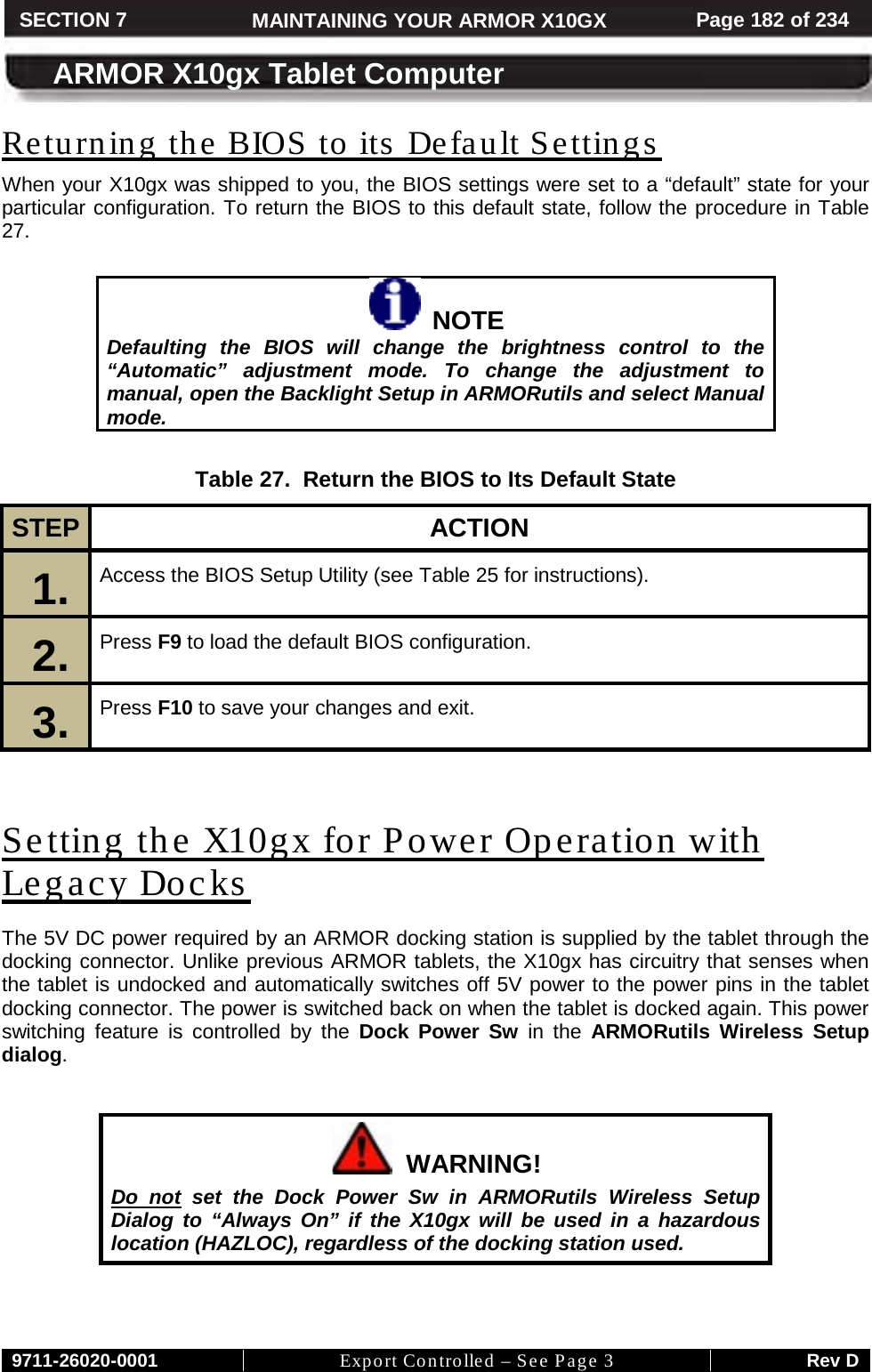
![9711-26020-0001 Export Controlled – See Page 3 Rev D SECTION 7 MAINTAINING YOUR ARMOR X10GX Page 180 of 234 ARMOR X10gx Tablet Computer Changing the BIOS Settings Follow the procedure in Table 25 to access the BIOS setup utility and verify settings or make changes. You can use the active pen (not a stylus or fingertip) to navigate the setup screens and select options, or you can connect an external keyboard to one of the USB ports. Contact DRS Technical Support if you have any questions about the BIOS settings for your ARMOR X10gx. CAUTION! Incorrectly setting the BIOS options could cause the X10gx to become unstable or render it completely inoperable. Move carefully through the menus and use caution when making changes. Read the description of each change in the right-hand column before making any adjustments. NOTE If you make permanent changes as a result of an upgrade or addition of new equipment, be sure to keep a record of the changes. Table 26 provides a handy place to record these changes. Always record the previous value in case you have to return to that value. Table 25. Access the BIOS Setup Utility. STEP ACTION COMMENTS 1. Start the computer and as soon as the DRS logo appears tap on the screen until you hear a beep. The Information tab of the Setup Utility will be displayed. 2. Click on a tab at the top of the screen to select a different menu page. 3. A listed menu option with a triangle to the left of it indicates an available submenu. Double-click on this option to open the sub-menu. 4. Click once on a bracketed setting [XXXXX] to select that menu option. A selected option will change to white text. If an item does not have a bracketed setting, there are no setting options available.](https://usermanual.wiki/DRS-Tactical-Systems/633ANH/User-Guide-1497857-Page-181.png)