DRS Tactical Systems GOBI2 Gobi2000 PCI Express Mini Card User Manual Manual
DRS Tactical Systems, Inc. Gobi2000 PCI Express Mini Card Manual
UserManual.wiki
>
DRS Tactical Systems
>
GOBI2 User Manual
>
Manual
Contents
1.
Host Manual
2.
Manual
Manual
Navigation menu
Upload a User Manual
Namespaces
Wiki Guide
HTML
PDF
Info
Views
User Manual
Discussion / Help
Navigation
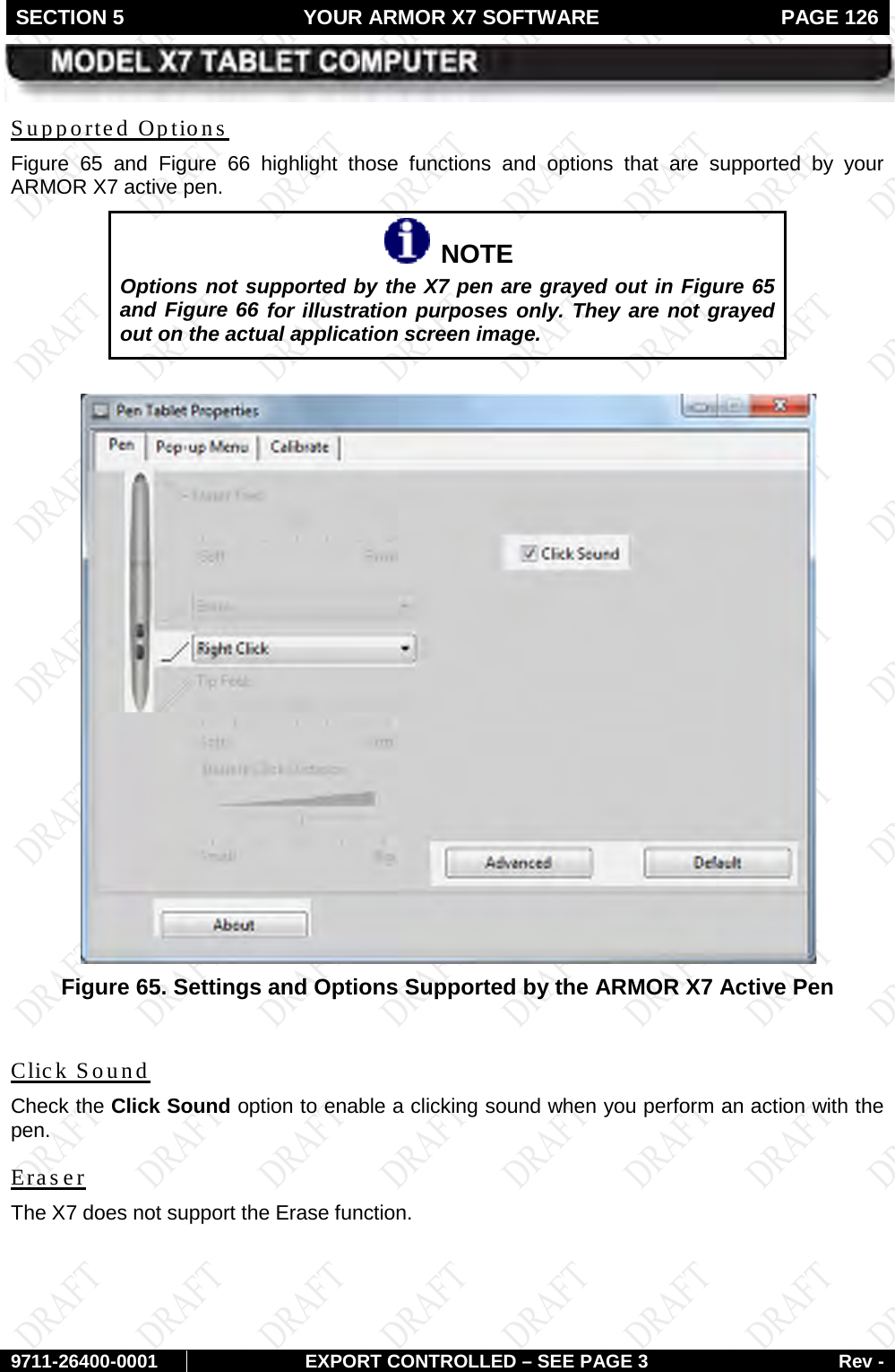
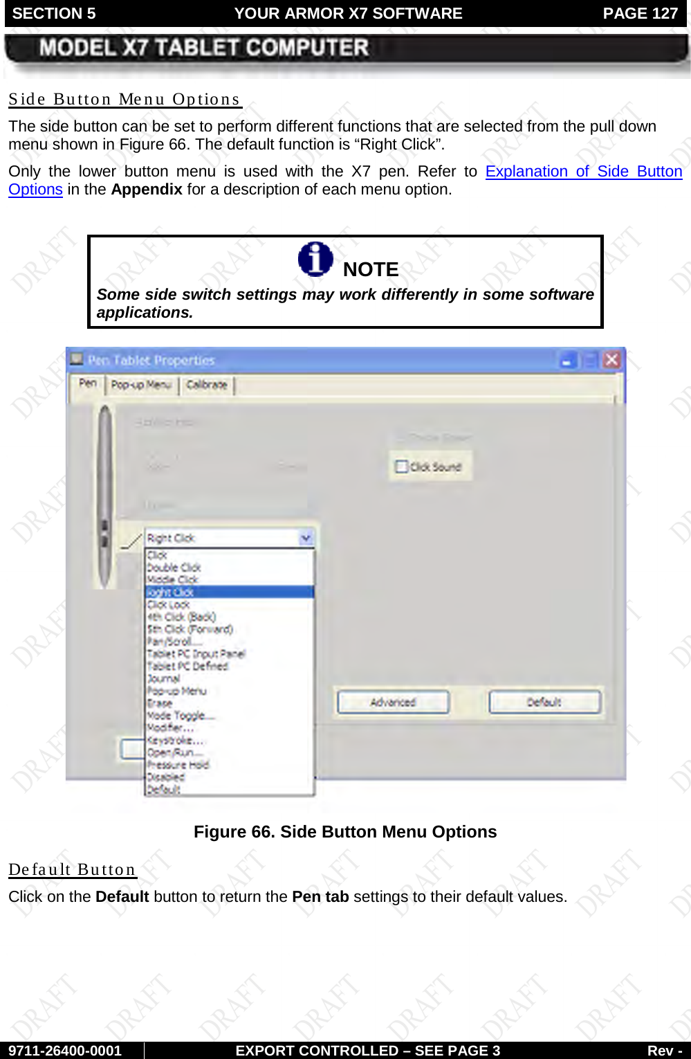
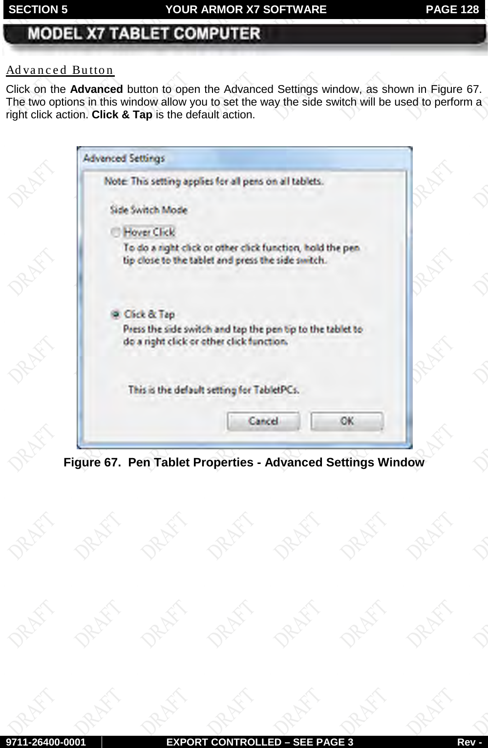
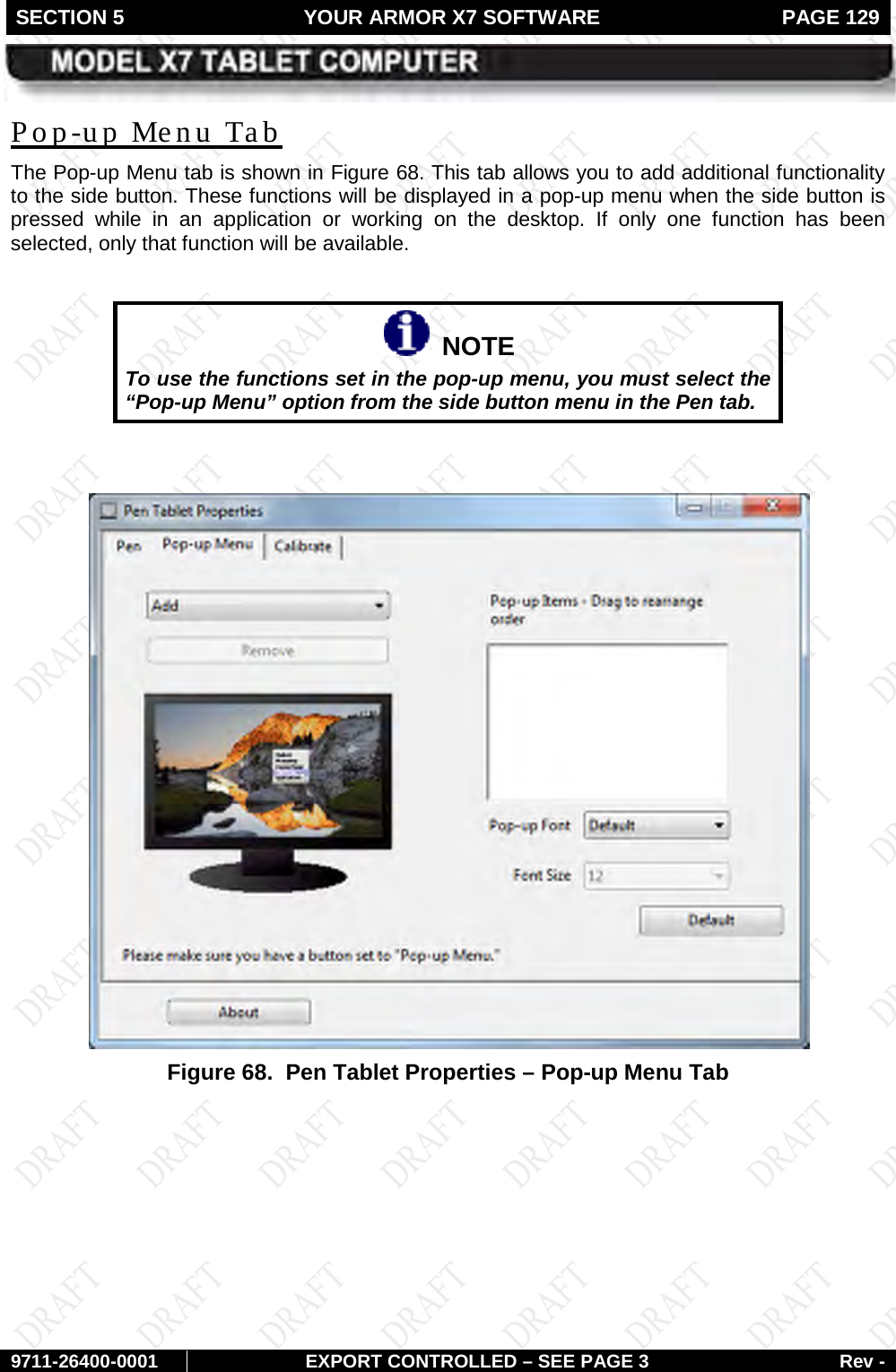
![FRONT MATTER CONTENT PAGE 3 9711-26020-0001 Rev - MODEL X10 TABLET COMPUTER Trade Compliance Statement THIS DOCUMENT CONTAINS TECHNOLOGY CONTROLLED UNDER THE U.S. EXPORT ADMINISTRATION REGULATIONS (EAR) AND MAY NOT BE EXPORTED OR TRANSFERRED TO ANY FOREIGN PERSON, FOREIGN COUNTRY OR FOREIGN ENTITY, BY ANY MEANS, WITHOUT PRIOR WRITTEN APPROVAL FROM THE U.S. DEPARTMENT OF COMMERCE, BUREAU OF INDUSTRY AND SECURITY (BIS) AND DRS TECHNOLOGIES. THE INFORMATION DISCLOSED IN THIS DOCUMENT IS PROPRIETARY DATA OF DRS TACTICAL SYSTEMS, INC., AND MAY NOT BE REPRODUCED, USED, OR DISCLOSED WITHOUT THE PRIOR WRITTEN AUTHORIZATION OF DRS TACTICAL SYSTEMS, INC. DISTRIBUTION AUTHORIZED FOR USE PER DOCUMENT NUMBER 9120-02737-0100. VALIDATION REQUIRED FOR PLANNING, TESTING, INSPECTION, MANUFACTURING, PROCUREMENT AND QUOTES. Other Compliance: • This equipment has been tested and found to comply with the limits for a Class B digital device, pursuant to Part 15 of the FCC Rules. These limits are designed to provide reasonable protection against harmful interference in a residential installation. This equipment generates, uses and can radiate radio frequency energy and, if not installed and used in accordance with the instructions, may cause harmful interference to radio communications. However, there is no guarantee that interference will not occur in a particular installation. If this equipment does cause harmful interference to radio or television reception, which can be determined by turning the equipment off and on, the user is encouraged to try to correct the interference by one or more of the following measures: o Reorient or relocate the receiving antenna. o Increase the separation between the equipment and receiver. o Connect the equipment into an outlet on a circuit different o from that to which the receiver is connected. o Consult the dealer or an experienced radio/TV technician for help. • This device complies with Part 15 of the FCC Rules. Operation is subject to the following two condition: (1) This device may not cause harmful interference, and (2) This device must accept any interference received, including interference that may cause undesired operation. • For body-worn operation, this computer has been tested and meets the FCC RF exposure guidelines set forth for an uncontrolled environment when used with ARMOR supplied accessories, or accessories designed specifically for this product. Use of other accessories may not ensure compliance with FCC RF exposure guidelines. • This X7 tablet computer has been tested for compliance with ATEX directive 94/9/EC. • This Class B digital apparatus complies with Canadian ICES-003, Issue 4 June 7, 2004 and RSS-210, Issue No 7 (June 2007) and No 5 (Nov 2001). • Cet appariel numérique de la classe B est conforme à la norme NMB-003, No. 4, June 7, 2004; et CNR-210, No 7 (June 2007) et No 5 (Nov 2001). • [In Canada], this product is restricted to indoor use due to its operation in the 5.15 to 5.25-GHz frequency range. Industry Canada requires this product to be used indoors to reduce the potential for harmful interference to co-channel mobile satellite systems.](https://usermanual.wiki/DRS-Tactical-Systems/GOBI2.Manual/User-Guide-1392756-Page-3.png)
![FRONT MATTER CONTENT PAGE 4 9711-26400-0001 EXPORT CONTROLLED – SEE PAGE 3 Rev - • To prevent radio interference to the licensed service [in Canada], this device is intended to be operated indoors and away from windows to provide maximum shielding. Equipment (or its transmit antenna) that is installed outdoors is subject to licensing. • Pour empêcher que cet appareil cause du brouillage au service faisant l'objet d'une licence, il doit être utilisé a l'intérieur et devrait être placé loin des fenêtres afinde fournir un écran de blindage maximal. Si le matériel (ou son antenne d'émission) est installé à l'extérieur, il doit faire l'objet d'une licence.](https://usermanual.wiki/DRS-Tactical-Systems/GOBI2.Manual/User-Guide-1392756-Page-4.png)
![FRONT MATTER PAGE 10 9711-26400-0001 EXPORT CONTROLLED – SEE PAGE 3 Rev - CAUTION! DO NOT use this unit in classified areas unsuitable for its security ratings. NE PAS UTILISER CETTE UNITÉ EN ZONES AINSI CLASSÉES IMPROPRES À SA COTE DE SÉCURITÉ CAUTION! When using IEEE 802.11a wireless LAN [in Canada], this product is restricted to indoor use due to its operation in the 5.15- to 5.25-GHz frequency range. Industry Canada requires this product to be used indoors for the frequency range of 5.15 GHz to 5.25 GHz to reduce the potential for harmful interference to co-channel mobile satellite systems. High power radar is allocated as the primary user of the 5.25- to 5.35-GHz and 5.65 to 5.85-GHz bands. These radar stations can cause interference with and/or damage to this device.](https://usermanual.wiki/DRS-Tactical-Systems/GOBI2.Manual/User-Guide-1392756-Page-10.png)

![SECTION 7 MAINTAINING YOUR ARMOR X7 PAGE 166 9711-26400-0001 EXPORT CONTROLLED – SEE PAGE 3 Rev - Figure 79. ARMORutils Event Recording Window [Update image to Win 7]](https://usermanual.wiki/DRS-Tactical-Systems/GOBI2.Manual/User-Guide-1392756-Page-166.png)
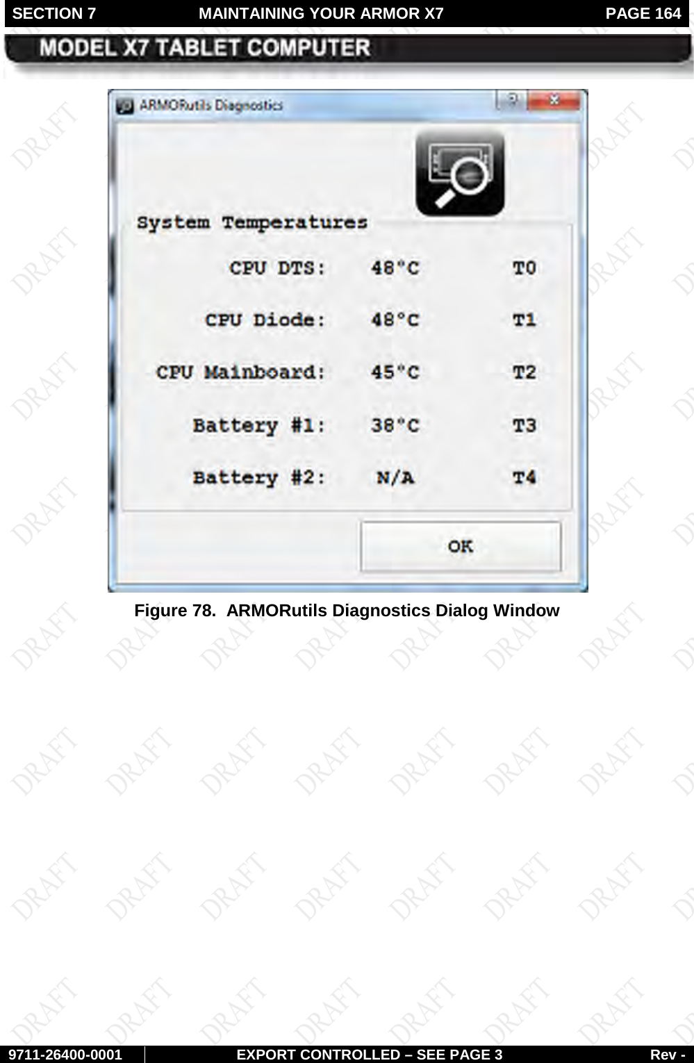
![SECTION 7 MAINTAINING YOUR ARMOR X7 PAGE 167 9711-26400-0001 EXPORT CONTROLLED – SEE PAGE 3 Rev - Figure 80. Sample Temperature Log File [“Core X” column headers do not correspond to Diagnostics dialog window titles (T0, T1, T2….) “System Temp” column header is “Core T2” in the Diagnostics dialog window titles]](https://usermanual.wiki/DRS-Tactical-Systems/GOBI2.Manual/User-Guide-1392756-Page-167.png)