DRS Tactical Systems GOBI2 Gobi2000 PCI Express Mini Card User Manual Manual
DRS Tactical Systems, Inc. Gobi2000 PCI Express Mini Card Manual
Contents
- 1. Host Manual
- 2. Manual
Manual
USER’S GUIDE | REVISION -
MODEL X7 TABLET COMPUTER
Copyright 2008-2009, DRS Tactical Systems, Inc., Melbourne, Florida. All Rights Reserved.
FRONT MATTER
CONTENT
PAGE 2
9711-26400-0001
EXPORT CONTROLLED – SEE PAGE 3
Rev -
To learn more about optional ARMOR accessories, please call 1-888-872-1100

FRONT MATTER
CONTENT
PAGE 3
9711-26020-0001
Rev -
MODEL X10 TABLET COMPUTER
Trade Compliance Statement
THIS DOCUMENT CONTAINS TECHNOLOGY CONTROLLED UNDER THE U.S. EXPORT ADMINISTRATION REGULATIONS (EAR) AND MAY
NOT BE EXPORTED OR TRANSFERRED TO ANY FOREIGN PERSON, FOREIGN COUNTRY OR FOREIGN ENTITY, BY ANY MEANS,
WITHOUT PRIOR WRITTEN APPROVAL FROM THE U.S. DEPARTMENT OF COMMERCE, BUREAU OF INDUSTRY AND SECURITY (BIS) AND
DRS TECHNOLOGIES.
THE INFORMATION DISCLOSED IN THIS DOCUMENT IS PROPRIETARY DATA OF DRS TACTICAL SYSTEMS, INC., AND MAY NOT BE
REPRODUCED, USED, OR DISCLOSED WITHOUT THE PRIOR WRITTEN AUTHORIZATION OF DRS TACTICAL SYSTEMS, INC.
DISTRIBUTION AUTHORIZED FOR USE PER DOCUMENT NUMBER 9120-02737-0100. VALIDATION REQUIRED FOR PLANNING, TESTING,
INSPECTION, MANUFACTURING, PROCUREMENT AND QUOTES.
Other Compliance:
• This equipment has been tested and found to comply with the limits for a Class B
digital device, pursuant to Part 15 of the FCC Rules. These limits are designed to
provide reasonable protection against harmful interference in a residential installation.
This equipment generates, uses and can radiate radio frequency energy and, if not
installed and used in accordance with the instructions, may cause harmful interference
to radio communications. However, there is no guarantee that interference will not
occur in a particular installation. If this equipment does cause harmful interference to
radio or television reception, which can be determined by turning the equipment off
and on, the user is encouraged to try to correct the interference by one or more of the
following measures:
o Reorient or relocate the receiving antenna.
o Increase the separation between the equipment and receiver.
o Connect the equipment into an outlet on a circuit different
o from that to which the receiver is connected.
o Consult the dealer or an experienced radio/TV technician for help.
• This device complies with Part 15 of the FCC Rules. Operation is subject to the
following two condition:
(1) This device may not cause harmful interference, and
(2) This device must accept any interference received, including interference that may
cause undesired operation.
• For body-worn operation, this computer has been tested and meets the FCC RF
exposure guidelines set forth for an uncontrolled environment when used with ARMOR
supplied accessories, or accessories designed specifically for this product. Use of
other accessories may not ensure compliance with FCC RF exposure guidelines.
• This X7 tablet computer has been tested for compliance with ATEX directive 94/9/EC.
• This Class B digital apparatus complies with Canadian ICES-003, Issue 4 June 7,
2004 and RSS-210, Issue No 7 (June 2007) and No 5 (Nov 2001).
• Cet appariel numérique de la classe B est conforme à la norme NMB-003, No. 4, June
7, 2004; et CNR-210, No 7 (June 2007) et No 5 (Nov 2001).
• [In Canada], this product is restricted to indoor use due to its operation in the 5.15 to
5.25-GHz frequency range. Industry Canada requires this product to be used indoors
to reduce the potential for harmful interference to co-channel mobile satellite systems.

FRONT MATTER
CONTENT
PAGE 4
9711-26400-0001
EXPORT CONTROLLED – SEE PAGE 3
Rev -
• To prevent radio interference to the licensed service [in Canada]
, this device is
intended to be operated indoors and away from windows to pro
vide maximum
shielding. Equipment (or its transmit antenna) that is installed outdoors is subject to
licensing.
• Pour empêcher que cet appareil cause du brouillage au service faisant l'objet d'une
licence, il doit être utilisé a l'intérieur et devrait être placé loin des fenêtres afinde
fournir un écran de blindage maximal. Si le matériel (ou son antenne d'émission) est
installé à l'extérieur, il doit faire l'objet d'une licence.
FRONT MATTER PAGE 5
9711-26400-0001
EXPORT CONTROLLED – SEE PAGE 3
Rev -
FRONT MATTER PAGE 6
9711-26400-0001
EXPORT CONTROLLED – SEE PAGE 3
Rev -
NOTICE
Information contained herein is for reference only and does not constitute a commitment on the
part of the manufacturer or any subsequent vendor. They are in no way responsible for any loss
or damage resulting from the use (or misuse) of this publication.
We at DRS strive to make this document as accurate as possible. However, errors do occur and
product information and settings may become out of date as a result of hardware changes or
software updates. DRS Tactical Systems, Inc. reserves the right to revise this publication or to
change its content without notice. Please contact DRS Technical Support for information
concerning updates to this document.
This publication and any accompanying software may not, in whole or in part, be copied,
photocopied, translated or reduced to any machine readable form without prior consent from
DRS Tactical Systems, Inc, except for copies kept by the purchaser for backup purposes.
Brand and product names mentioned in this publication may or may not be registered
trademarks their respective companies but should be treated as such. They are mentioned for
identification purposes only and are not intended as an endorsement of that product or its
manufacturer. All reproductions of software applications, quoted text and illustrations are
copyrighted by their respective owners.
Copyright 2010, DRS Tactical Systems, Inc., Melbourne, Florida. All Rights Reserved
FRONT MATTER PAGE 7
9711-26400-0001
EXPORT CONTROLLED – SEE PAGE 3
Rev -
WARNING SUMMARY
This device is a Class I, Division 2, Groups A-D, T5 product. The ARMOR X7 complies with all
applicable industrial health and safety requirements. However there are certain safety
considerations such as battery safety that you need to be aware of. Please read and comply
with all warnings and cautions in this guide and in all other X7 documentation.
A “ Warning!” notice indicates a condition or action that could possibly result in injury or
death to the user. A “ Caution!” notice indicates a condition or action that could result in
loss of data or damage to equipment.
WARNING!
EXPLOSION HAZARD – DO NOT DISCONNECT WHILE CIRCUIT IS
LIVE UNLESS AREA IS KNOWN TO BE NON-HAZARDOUS.
AVERTISSEMENT-RISQUE D'EXPLOSION - NE PAS DÉBRANCHER
TANT QUE LE CIRCUIT EST SOUS TENSION, À MOINS QU'IL NE
S'AGISSE D'UN EMPLACEMENT NON DANGEREUX.
WARNING!
EXPLOSION HAZARD – BATTERIES MUST ONLY BE CHANGED IN
AN AREA KNOWN TO BE NON-HAZARDOUS.
AVERTISSEMENT-RISQUE D'EXPLOSION - AFIN D'ÉVITER TOUT
RISQUE D'EXPLOSION, S'ASSURER QUE L'EMPLACEMENT EST
DÉSIGNÉ NON DANGEREUX AVANT DE CHANGER LA BATTERIE.
WARNING!
CAUTION: RIS K OF EXPLOS ION IF BATTERY IS
REPLACED BY
AN INCORRECT TYPE. DISPOSE OF USED BATTERIES
ACCORDING TO INSTRUCTIONS IN THIS USER'S GUIDE.
ATTENTION: RISQUE D'EXPLOSION SI LA BATT
ERIE EST
REMPLACEE PAR UN TYPE INCORRECT. JETER L
ES PILES
USAGEES CONFORMEMENT AUX INSTRUCTIONS
DANS CE
GUIDE D'UTILISATEUR..
FRONT MATTER PAGE 8
9711-26400-0001
EXPORT CONTROLLED – SEE PAGE 3
Rev -
WARNING!
Do not drop or mishandle the batteries, immerse them in water, or
subject them to high heat. Doing so could increase the risk of
explosion or leakage, and possibly cause injury.
WARNING!
The lithium-
ion batteries used in this equipment contain material
that is hazardous to your health. If battery contents come in contact
with the eyes, IMMEDIATELY flush the affected area with clean
water for 15 minutes and have
someone else summon medical
attention for you. Unaffected persons should assist the affected
individual in the vital first flushing of the eyes.
WARNING!
If battery material comes in contact with the skin, flush the affected
area with clean water and seek immediate medical treatment.
WARNING!
Place all shipping bags and packing materials safely out of the
reach of small children, especially infants and toddlers. These
items may pose a choking or suffocation hazard.
WARNING!
Changes or modifications not performed by, or expressly authorized
by, DRS Tactical Systems, Inc
could be hazardous to your health,
could cause damage to the equipment, could void your warranty,
could void your authority to operate the equipment, or could result
in all of the above.
FRONT MATTER PAGE 9
9711-26400-0001
EXPORT CONTROLLED – SEE PAGE 3
Rev -
CAUTION!
Use this product only in vehicles that can supply a regulated +11 to
+16 DC voltage. For vehicle battery systems outside of this range, a
voltage adapter is required to prevent damage to the computer.
CAUTION!
DO NOT connect the DC power supply from a Rapid Battery
Charger into the computer or docking mechanism. This power
supply is 24 VDC and will cause permanent damage to the
computer.
CAUTION!
DO NOT connect the computer to more than one power source at a
time such as with the AC adapter connected to the computer and
vehicle power connected to the docking station. Permanent
damage to the X7 batteries or to the computer itself may result.
CAUTION!
When using the provided AC adapter, the maximum safe ambient
operating temperature is 40°C.
CAUTION!
Use only the battery originally supplied with your ARMOR X7 or
one recommended by DRS.
The use of any other battery could
create a hazardous condition and possibly damage your computer.
CAUTION!
Recharging the battery must only be carried out in a non-
hazardous area using the supplied AC adapter. The definition of
hazardous areas can be found in Standard EN 60079-10.
FRONT MATTER PAGE 10
9711-26400-0001
EXPORT CONTROLLED – SEE PAGE 3
Rev -
CAUTION!
DO NOT use this unit in classified areas unsuitable for its security
ratings.
NE PAS UTILISER CETTE UNITÉ EN ZONES AINSI
CLASSÉES IMPROPRES À SA COTE DE SÉCURITÉ
CAUTION!
When using IEEE 802.11a wireless LAN [in Canada], this product is
restricted to indoor use due to its operation in the 5.15- to 5.25-
GHz frequency range. Industry Canada requires this product to be
used indoors for the frequency range of 5.15 GHz to 5.25 GHz to
reduce the potential for harmful interference to co-channel mobile
satelli
te systems. High power radar is allocated as the primary
user of the 5.25- to 5.35-GHz and 5.65 to 5.85-GHz bands. These
radar stations can cause interference with and/or damage to this
device.

FRONT MATTER PAGE 11
9711-26400-0001
EXPORT CONTROLLED – SEE PAGE 3
Rev -
Table of Contents
WARNING SUMMARY ........................................................................................................... 7
1. Welcome and Introduction ................................................................. 22
Your ARMOR X7 Purchase ...................................................................................................23
About This Guide ...................................................................................................................24
Viewing, Navigating, and Printing this Guide ..........................................................................24
Terminology Used in this Guide .............................................................................................24
Please Help Us Maintain Top Quality Documentation ............................................................24
2. LEARNING ABOUT YOUR ARMOR X7 ............................................... 26
Processor and Operating System ..........................................................................................26
Data Storage .........................................................................................................................26
Dual Screen Display ..............................................................................................................26
Video Graphics ......................................................................................................................27
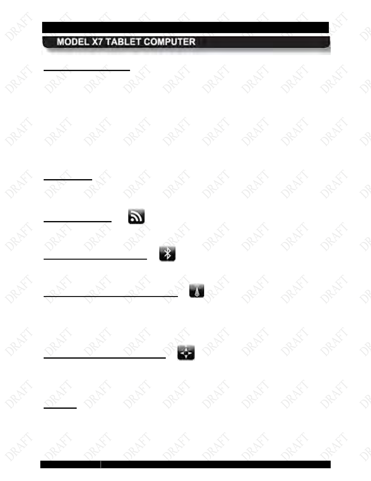
Wireless .................................................................................................................................27
Wireless LAN ....................................................................................................................27
Bluetooth Capability ..........................................................................................................27
Optional WWAN Support ...................................................................................................27
Optional GPS Capability ........................................................................................................27
Audio .....................................................................................................................................27
Batteries ................................................................................................................................28
Flexspace™ ...........................................................................................................................28
Specifications ........................................................................................................................29
Front Panel Features .............................................................................................................35
Left and Right Control Panels ............................................................................................36
Indicator Panel ..................................................................................................................38
Ambient Light Sensor (ALS) ..............................................................................................39
Speaker .............................................................................................................................39
Noise Cancelling Stereo Microphones ...............................................................................39
Rear Panel Features ..............................................................................................................39
Cooling Register ................................................................................................................40
Batteries ............................................................................................................................41
Webcam ............................................................................................................................42
Bottom Panel Features ..........................................................................................................43
Included Components, Accessories and Support ...................................................................44

FRONT MATTER PAGE 12
9711-26400-0001
EXPORT CONTROLLED – SEE PAGE 3
Rev -
Active Pen with Tether .......................................................................................................44
AC Adapter and Power Cord .............................................................................................44
ARMOR Cloth ...................................................................................................................45
Subscriber Identity Module (SIM) Card Support.................................................................45
Secure Digital (SD) Card Reader Support .........................................................................45
Trusted Platform Module (TPM) Support ...........................................................................45
Optional Add-ons and Accessories for Your X7 .....................................................................46
Wireless Wide Area Network (WWAN) Radio ....................................................................46
GPS Radio ........................................................................................................................46
Compact Keyboard ............................................................................................................46
Desk Dock .........................................................................................................................47
Vehicle Dock .....................................................................................................................48
ARMOR Flexspace™ Adapter ...........................................................................................49
3. GETTING STARTED ............................................................................ 51
Installing and Charging the Batteries .....................................................................................52
Turning On Your X7 for the First Time ...................................................................................55
Turning the Computer On Normally .......................................................................................55
Putting the Computer in Sleep Mode .....................................................................................55
Turning the Computer Off Normally .......................................................................................55
Emergency Shutdown ............................................................................................................56
Indicator State Summary .......................................................................................................56
Activating your Wireless Radios .............................................................................................58
Installing a Micro SD or SDHC Card ......................................................................................58
Configuring your Audio System ..............................................................................................58
Configuring your Microphones ...........................................................................................59
Operating the X7 Display .......................................................................................................61
Adjusting the Screen Brightness ........................................................................................61
Automatic Adjustment........................................................................................................62
Automatic Mode Profiles ....................................................................................................63
Working with the Pen Screen .................................................................................................64
Your X7 Active Pen ...........................................................................................................64
Using the X7 Pen with the Pen Screen ..............................................................................64
Pen Screen Adjustments ...................................................................................................65
Pen Screen Calibration ......................................................................................................65

FRONT MATTER PAGE 13
9711-26400-0001
EXPORT CONTROLLED – SEE PAGE 3
Rev -
Working with the Touch Screen .............................................................................................66
Working with the Touch Screen .........................................................................................66
Touch Screen Adjustments................................................................................................66
Touch Screen Calibration ..................................................................................................67
Entering Data Using the Input Panel ......................................................................................68
Operating Modes ...............................................................................................................68
Editing Documents ............................................................................................................69
Opening Input Panel with a Gesture ..................................................................................69
Using the FPS as a Simple Mouse Device .............................................................................70
Operating with the ARMOR X7 Vehicle Dock .........................................................................73
X7 RF and Non-RF Vehicle Docks ....................................................................................73
Using the X7 Vehicle Dock ................................................................................................73
Using the Webcam ................................................................................................................76
Capturing Images and Video .............................................................................................76
Scanning a Barcode ..........................................................................................................77
Using the Screen Magnifier ....................................................................................................81
Tips for Proper Use and Care Of Your X7 ..............................................................................82
4. Networking .......................................................................................... 84
Managing your WI-FI Radio ...................................................................................................84
Managing Your Bluetooth Connections ..................................................................................86
If you have the Optional WWAN Radio ..................................................................................89
Installing the Subscriber Identity Module (SIM) ..................................................................89
Connecting to a WWAN .....................................................................................................91
If you have the Optional GPS Receiver ..................................................................................93
Enabling and Disabling Your Wireless Radios .......................................................................95
Wireless Signal Quality ..........................................................................................................96
5. Your ARMOR X7 Software .................................................................. 97
Getting Started with Windows 7 .............................................................................................99
Help for Windows ..............................................................................................................99
ARMORutils Application ....................................................................................................... 100
ARMORutils Main Window .............................................................................................. 100
Backlight Setup Dialog Window ....................................................................................... 101
Wireless Devices Dialog Window .................................................................................... 103
Programmable Button (PB) Settings Dialog ..................................................................... 105

FRONT MATTER PAGE 14
9711-26400-0001
EXPORT CONTROLLED – SEE PAGE 3
Rev -
Configuration Dialog Window .......................................................................................... 107
Battery Monitor Dialog Window ....................................................................................... 109
Screen Mode Setup Dialog Window ................................................................................ 113
Diagnostics Dialog Window ............................................................................................. 115
ARMORutils About Window ............................................................................................. 116
Pen and Touch Utility ........................................................................................................... 117
Pen Options Tab ............................................................................................................. 117
Flicks Tab ........................................................................................................................ 119
Handwriting Tab .............................................................................................................. 119
Touch Tab ....................................................................................................................... 121
Tablet PC Settings Utility ..................................................................................................... 123
Display Tab ..................................................................................................................... 123
Other Tab ........................................................................................................................ 124
Pen Tablet Properties Utility................................................................................................. 125
Pen Tab .......................................................................................................................... 125
Pop-up Menu Tab ............................................................................................................ 129
Calibrate Tab ................................................................................................................... 131
Realteck® HD Audio Manager Application ........................................................................... 132
Picasa 3® ............................................................................................................................ 133
Virtual Magnifying Glass™ ................................................................................................... 134
6. Troubleshooting................................................................................ 135
Determining the Problem ..................................................................................................... 135
Troubleshooting Flowcharts ................................................................................................. 139
TS-01 Tablet will not power up ........................................................................................ 139
TS-02 Tablet will not start boot process. Power is ok ...................................................... 140
TS-03 Tablet will not boot into Windows .......................................................................... 141
TS-04 Tablet will not recognize a battery ......................................................................... 142
TS-05 Tablet is locked up ................................................................................................ 143
TS-06 Cannot connect to wireless network ..................................................................... 144
7. Maintaining Your ARMOR X7 ........................................................... 147
Removing and Replacing the Solid State Drive .................................................................... 147
Removing and Replacing the Batteries ................................................................................ 150
Installing a SIM Card ........................................................................................................... 152
Installing a Micro SD or SDHC Card .................................................................................... 155

FRONT MATTER PAGE 15
9711-26400-0001
EXPORT CONTROLLED – SEE PAGE 3
Rev -
Changing the BIOS Settings ................................................................................................ 157
Returning the BIOS to its Default Settings ....................................................................... 159
Changing the Power Button Default Action .......................................................................... 160
Caring For the Display Screen ............................................................................................. 162
Monitoring the Health of Your ARMOR X7 ........................................................................... 163
Generating a Log of Temperature Variations ................................................................... 165
8. Display Management ........................................................................ 168
Adjusting the Brightness ...................................................................................................... 168
Manual Brightness Adjustment ........................................................................................ 168
Automatic Adjustment...................................................................................................... 169
Automatic Mode Profiles .................................................................................................. 169
Calibrating the Display ......................................................................................................... 170
Using ARMORutils .......................................................................................................... 170
Using the Tablet PC Settings Utility in Control Panel ....................................................... 170
Rotating the Screen (Touch or Pen) ..................................................................................... 173
Using the Intel Graphics Options ..................................................................................... 173
Using the Intel Graphics and Media Control Panel .......................................................... 174
Using a Keyboard “Hot Key” Combination ....................................................................... 175
9. Battery Management ......................................................................... 177
Safety and Handling Considerations for Your Batteries ........................................................ 178
When to Charge a Battery ................................................................................................... 178
Newly Received Batteries ................................................................................................ 178
Disconnected Batteries .................................................................................................... 179
Installed Batteries ............................................................................................................ 179
Fully Depleted Batteries .................................................................................................. 180
How to Charge Your Batteries ............................................................................................. 180
Battery Operating Times ...................................................................................................... 183
Operating under Low Battery Conditions.............................................................................. 183
What to Do if You Get a Low Battery Alert ....................................................................... 184
Avoiding Overly-Discharging Your Batteries .................................................................... 184
What to Do for Overly-Discharged Batteries .................................................................... 184
Battery Capacity .................................................................................................................. 185
Discharge/Recharge Cycles................................................................................................. 185
Battery Conditioning ............................................................................................................ 186

FRONT MATTER PAGE 16
9711-26400-0001
EXPORT CONTROLLED – SEE PAGE 3
Rev -
How to Optimize Battery Operating Time ............................................................................. 189
How to Monitor Battery Usage ............................................................................................. 189
Open the Task Bar Battery Window ................................................................................. 189
Open the ARMORutils Battery Monitor Page ................................................................... 190
When to Replace a Battery .................................................................................................. 191
Battery Warranty .................................................................................................................. 191
Where to Purchase Replacement Batteries ......................................................................... 191
How to Store Batteries When Not in Use ............................................................................. 192
Short-Term Storage ......................................................................................................... 192
Long-Term Storage ......................................................................................................... 192
Battery Tips for Best Performance ....................................................................................... 192
Disposing Of Your Batteries ................................................................................................. 193
10. DRS Technical Support .................................................................. 195
Before You Contact Us ........................................................................................................ 195
How to Obtain Warranty Service .......................................................................................... 195
If You Need Further Information ........................................................................................... 197
Warranty Information ........................................................................................................... 198
General Information ......................................................................................................... 198
Length of Warranty .......................................................................................................... 198
Terms and Conditions ..................................................................................................... 198
Additional Information ...................................................................................................... 199
Acronyms............................................................................................................................. 200
Glossary .............................................................................................................................. 201
Appendix A .......................................................................................................................... 202
Explanation of Pen Side Button Options .......................................................................... 202
Appendix B .......................................................................................................................... 203
Using the X7 External Battery Charger ............................................................................ 203
Charger LED Status Indications ........................................................................................... 204

FRONT MATTER PAGE 17
9711-26400-0001
EXPORT CONTROLLED – SEE PAGE 3
Rev -
List of Figures
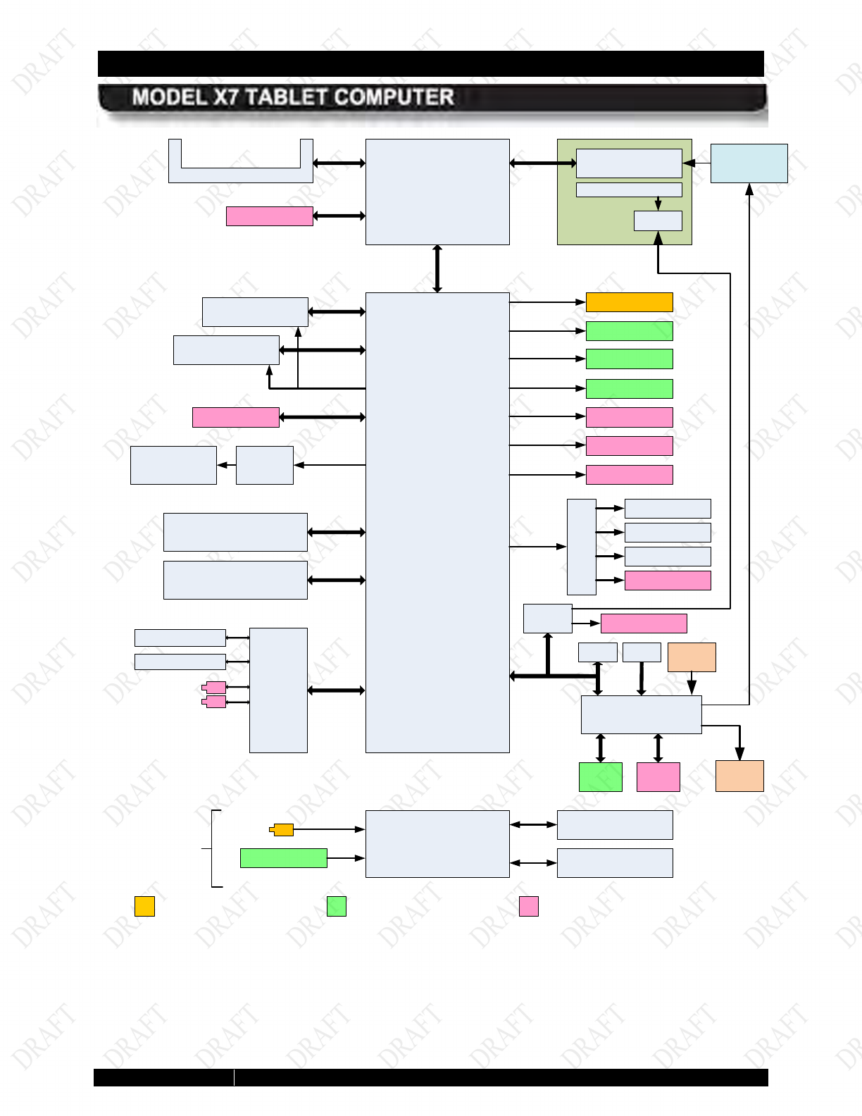
Figure 1. X7 Internal Block Diagram .........................................................................................33
Figure 2. ARMOR X7 Key Features – Front View ...................................................................35
Figure 3. X7 Control Panels .....................................................................................................36
Figure 4. Indicator Panel ..........................................................................................................38
Figure 5. Key Features - Rear Panel ........................................................................................40
Figure 6. X7 Battery Bays ........................................................................................................41
Figure 7. X7 Webcam ..............................................................................................................42
Figure 8. Key Features – Bottom Panel ....................................................................................43
Figure 9. The ARMOR X7 Pen ..................................................................................................44
Figure 10. ARMOR X7 AC Adapter ..........................................................................................44
Figure 11. ARMOR Microfiber Cleaning Cloth ...........................................................................45
Figure 12. Compact Keyboard .................................................................................................46
Figure 13. X7 Desk Dock .........................................................................................................47
Figure 14. X7 Vehicle Dock ......................................................................................................48
Figure 15. Examples of X7 Vehicle Dock Mounting Configurations ..........................................48
Figure 16. ARMOR X7 Flexspace™ Adapter Concept .............................................................49
Figure 17. X7 Batteries Positioned for Installation ....................................................................52
Figure 18. System Tray Battery Window ..................................................................................53
Figure 19. Battery Fuel Gauge ..................................................................................................54
Figure 20. Realtek HD Audio Manager - Speakers Main Tab ...................................................59
Figure 21. Microphone Main Tab ..............................................................................................60
Figure 22. Armor Utilities Screen – Backlight Tab ....................................................................62
Figure 23. Location of the Input Panel .......................................................................................68
Figure 24. Input Panel Keyboard Opened on Desktop ..............................................................68
Figure 25. FPS Sensor Properties Window ..............................................................................70
Figure 26. External Antenna Selection Options in ARMORutils .................................................74
Figure 27. Picasa Application Window .....................................................................................77
Figure 28. Sample Linear Barcode ...........................................................................................77
Figure 29. Webcam Barcode Scanner® Barcode Scanner Application Window .......................78
Figure 30. Sample 2D Barcode ................................................................................................79
Figure 31. QuickMark® Barcode Scanner Application Window ................................................80
Figure 32. A Captured 2D Barcode ..........................................................................................80
Figure 33. Virtual Magnifying Glass at Work .............................................................................81
Figure 34. Windows Network and Sharing Center ....................................................................85
Figure 35. Currently Connected and Available Wi-Fi Networks ................................................86
Figure 36. Devices and Printers Window ...................................................................................87
Figure 37. Bluetooth Settings Window .....................................................................................88
Figure 38. X7 Rear Compartment ............................................................................................90
Figure 39. Sierra OneClick Connection Manager Window ........................................................92
Figure 40. Settings Window ......................................................................................................92

FRONT MATTER PAGE 18
9711-26400-0001
EXPORT CONTROLLED – SEE PAGE 3
Rev -
Figure 41. U-Center GPS Application Window .........................................................................94
Figure 42. ARMORutils Wireless Devices Page .......................................................................95
Figure 43. Windows 7 Welcome Page .....................................................................................99
Figure 44. ARMORutils Main Window .................................................................................... 100
Figure 45. ARMORutils Backlight Setup Page ........................................................................ 101
Figure 46. ARMORutils Wireless Devices Page ..................................................................... 103
Figure 47. ARMORutils Programmable Button Settings Page ................................................. 105
Figure 48. ARMORutils Programmable Button Settings Page Menu Options .......................... 106
Figure 49. ARMORutils Configuration Page ........................................................................... 108
Figure 50. ARMORutils Battery Monitor Dialog ...................................................................... 109
Figure 51. ARMORutils Battery Information Window ............................................................... 110
Figure 52. ARMORutils Charger Control Settings Window ...................................................... 111
Figure 53. Battery Conditioning Dialog ................................................................................... 112
Figure 54. ARMORUtils Screen Setup Dialog ........................................................................ 113
Figure 55. ARMORutils Diagnostics Dialog ............................................................................ 115
Figure 56. ARMORutils About Window ................................................................................... 116
Figure 57. Pen and Touch Utility – Pen Options Tab .............................................................. 117
Figure 58. Pen and Touch Utility – Flicks Tab ........................................................................ 119
Figure 59. Pen and Touch Utility – Handwriting Tab .............................................................. 120
Figure 60. Pen and Touch Utility – Touch Tab ....................................................................... 121
Figure 61. Touch Tab Virtual Mouse Pointer .......................................................................... 122
Figure 62. Tablet PC Settings – Display Tab ........................................................................... 123
Figure 63. Tablet PC Settings Utility – Other Tab ................................................................... 124
Figure 64. WACOM Pen Tablet Properties Window – Pen Tab ............................................... 125
Figure 65. Settings and Options Supported by the ARMOR X7 Active Pen ............................. 126
Figure 66. Side Button Menu Options ..................................................................................... 127
Figure 67. Pen Tablet Properties - Advanced Settings Window ............................................. 128
Figure 68. Pen Tablet Properties – Pop-up Menu Tab ........................................................... 129
Figure 69. Pop-up Menu Add Options .................................................................................... 130
Figure 70. Pen Tablet Properties Window – Calibrate Tab ..................................................... 131
Figure 71. Picasa 3 Image Capture Application ...................................................................... 133
Figure 72. Virtual Magnifying Glass Application ...................................................................... 134
Figure 73. X7 Solid State Drive Location ................................................................................ 148
Figure 74. X7 Battery Pack Locations ..................................................................................... 151
Figure 75. X7 Rear Compartment .......................................................................................... 153
Figure 76. Micro SD Card Socket ............................................................................................ 155
Figure 77. Power Button Settings Options .............................................................................. 161
Figure 78. ARMORutils Diagnostics Dialog Window ............................................................... 164
Figure 79. ARMORutils Event Recording Window .................................................................. 166
Figure 80. Sample Temperature Log File ................................................................................ 167
Figure 81. Armor Utilities Screen – Backlight Tab .................................................................. 168
Figure 82. Tablet PC Settings Window .................................................................................... 170
FRONT MATTER PAGE 19
9711-26400-0001
EXPORT CONTROLLED – SEE PAGE 3
Rev -
Figure 83. Intel Graphics Screen Rotation Options (from icon tray) ........................................ 173
Figure 84. Intel Graphics and Media Control Panel ................................................................ 174
Figure 85. Intel Graphics Panel Hot Key Manager ................................................................. 175
Figure 86. Low Battery Alert Message ................................................................................... 183
Figure 87. ARMORutils Battery Conditioning Window ............................................................ 187
Figure 88. Battery Conditioning Start Alert Message .............................................................. 188
Figure 89. Windows Battery Window Icon Examples .............................................................. 190
Figure 90. ARMORutils Battery Monitor Page ........................................................................ 190
Figure 91. ARMOR X7 Battery Label Example ....................................................................... 191
Figure 92. Inserting a Battery ................................................................................................. 204
List of Tables
Table 1. Power Button Actions .................................................................................................37
Table 2. Install the X7 Batteries ...............................................................................................52
Table 3. X7 Indicator State Summary .......................................................................................56
Table 4. Configuring Your Speakers ........................................................................................58
Table 5. Configuring your Microphones ....................................................................................59
Table 6. Pen Screen Actions. ...................................................................................................64
Table 7. Stylus Actions. ............................................................................................................66
Table 8. Configuring the FPS Mouse Function .........................................................................70
Table 9. FPS Mouse Actions ....................................................................................................71
Table 10. Configuring the External Antennas ...........................................................................75
Table 11. Capturing a Still Image or Video ................................................................................76
Table 12. Scan UPC-10, EAN-13 and ISBN Barcodes in Windows 7 ........................................78
Table 13. Scan Datamatrix and QR Format Barcodes in Windows 7 .........................................80
Table 14. View and Manage Network Connections ..................................................................84
Table 15. View and Manage Bluetooth Devices .......................................................................86
Table 16. Installing a SIM .........................................................................................................89
Table 17. Connecting to a WWAN .............................................................................................91
Table 18. Configuring the u-Center com port ...........................................................................93
Table 19. Software Included with your X7 Purchase ................................................................97
Table 20. ARMOR X7 Trouble Symptoms .............................................................................. 135
Table 21. Remove and Replace the Solid State Drive ............................................................ 149
Table 22. Remove and Replace a Battery .............................................................................. 150
Table 23. Installing a SIM Card .............................................................................................. 152
Table 24. Installing the SC Card ............................................................................................ 155
Table 25. Access the BIOS Setup Utility. ................................................................................ 157
Table 26. Record Bios Changes Here .................................................................................... 158
Table 27. Return the BIOS to Its Default State ....................................................................... 159
Table 28. Changing the Power Button Default Actions ........................................................... 160
Table 29. Generate a Temperature Variation Log .................................................................. 165

FRONT MATTER PAGE 20
9711-26400-0001
EXPORT CONTROLLED – SEE PAGE 3
Rev -
Table 30. Calibrate the Display Using the Tablet PC Settings Utility ...................................... 170
Table 31. X7 Battery Charging Times .................................................................................... 181
Table 32. Select How to Charge the Batteries ........................................................................ 181
Table 33. X7 Battery Operating Times ................................................................................... 183
Table 34. Recover an Overly-discharged Battery. ................................................................... 185
Table 35. Conditioning a Battery ............................................................................................. 187
Table 36. Charging a Battery ................................................................................................. 203
Table 37. Status Indicator Conditions ..................................................................................... 204

FRONT MATTER PAGE 21
9711-26400-0001
EXPORT CONTROLLED – SEE PAGE 3
Rev -
This Page Intentionally Left Blank
SECTION 1 WELCOME AND INTRODUCTION PAGE 22
9711-26400-0001
EXPORT CONTROLLED – SEE PAGE 3
Rev -
1. WELCOME AND INTRODUCTION
Thank you for purchasing the ARMOR X7 ruggedized tablet computer with Intel® Mobile
technology. Your X7 is the first of a new line of durable, reliable, and easy-to-use small form
factor tablet computers.
Your new X7 is equipped with a high-resolution dual-screen LCD display that is readable even
in bright sunlight. In addition, you now have both a touch screen and
The X7 batteries are hot-swappable, which means you can change them one at a time without
interrupting normal computer operations and without the need for tools.
an active pen screen at
your fingertips.
We take pride in providing high-
quality products and superior customer
service. Thank you for choosing the DRS
ARMOR X7, and for your trust in the
ARMOR line of products.
The ARMOR Team
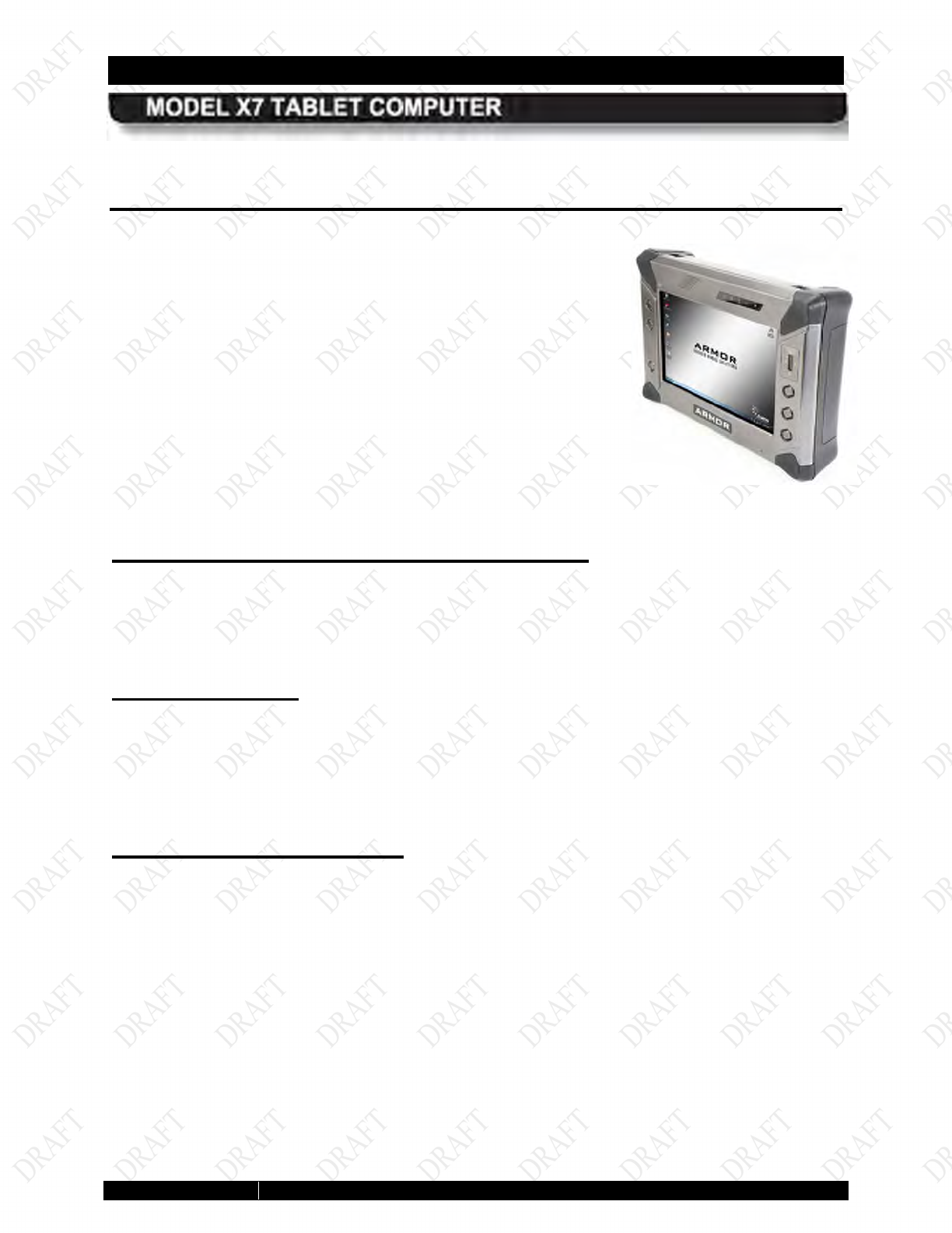
The ARMOR X7 ruggedized
tablet
computer can be
mounted in a vehicle dock or
desk docking station (shown
here in a desk dock.
SECTION 1 WELCOME AND INTRODUCTION PAGE 23
9711-26400-0001
EXPORT CONTROLLED – SEE PAGE 3
Rev -
Your purchase includes the items and accessories shown below. Please confirm that all of
these items are present and in good condition.
Your ARMOR X7 Purchase
NOTE: Your solid-state drive is shipped already installed in the computer. However, if you
ordered a WWAN card with your X7, a solid-state drive is not included.
Contact your ARMOR X7 computer sales representative if any item is missing or
damaged.
ARMOR X7 Included Components and Accessories
COMPUTER
QUICK START
GUIDE
AC
ADAPTER
BATTERIES (2)
SOLID-STATE
DRIVE

SECTION 1 WELCOME AND INTRODUCTION PAGE 24
9711-26400-0001
EXPORT CONTROLLED – SEE PAGE 3
Rev -
This user’s guide contains virtually all of the information required to setup and maintain your
ARMOR X7 computer. However, should you need additional technical information, please visit
our web site at:
About This Guide
www.drsarmor.com, or call DRS Technical Support toll-free at 1-888-872-1100.
This User’s Guide is installed on your ARMOR X7 computer in PDF format. To access it,
double-click on the icon on the desktop. You can click on any Figure or Table reference and on
the
Viewing, Navigating, and Printing this Guide
blue underlined text (links) to navigate within the guide or to access resources on the
Internet. Links to internet resources will change color after the first access to indicate the link
has been recently used; links to information within the document will not change color. The
latest version of Adobe PDF Reader is available for downloading free from www.adobe.com.
For best print results, use the Adobe Reader “Print “menu options.
As the result of long use and the evolution, some functions and buttons may be called by more
than one name and some of these names are used interchangeably, which can lead to
confusion. The following are some of the more common examples you may encounter in this
manual:
Terminology Used in this Guide
Standby = Stand By = Sleep
Windows Security Key Button = SAS Button = OEM Button = Side Button
This guide was produced with the latest information available and verified for accuracy at the
time of its release. However, mistakes are possible, and product updates may supersede the
information in this guide. We encourage you to contact DRS Technical Support toll-free at 1-
888-872-1100 with suggestions and corrections so that we can maintain the highest possible
quality documentation for you and for future customers.
Please Help Us Maintain Top Quality
Documentation

SECTION 1 WELCOME AND INTRODUCTION PAGE 25
9711-26400-0001
EXPORT CONTROLLED – SEE PAGE 3
Rev -
This Page Intentionally Left Blank
SECTION 2 LEARNING ABOUT YOUR ARMOR X7 PAGE 26
9711-26400-0001
EXPORT CONTROLLED – SEE PAGE 3
Rev -
2. LEARNING ABOUT YOUR ARMOR X7
The X7 is a rugged full-feature tablet PC with built-in Wi-Fi® and
Bluetooth networking. Its compact size and low weight, coupled
with a high-contrast display for use in bright sunlight, make it ideal
for field use. The X7 is rated IP67 for protection from dust, dirt,
water and other contaminating elements.
It is specifically designed to support a full 8-hour shift operating on
one set of batteries. However, its hot-swap battery access means
you can change the batteries without the need for tools and
without interrupting normal computer operations.
Like its big brother, the X10gx, the X7 has a dual mode Touch and
Pen screen supporting both finger navigation and detailed graphic
positioning using a pen or stylus. Your X7 is ready for use
anywhere, any time.
Processor and Operating System
The X7 contains an Intel® 1.6GHz Pineview-M single core processor with up to 2 GB of 667
MHz DDR2 memory and 512 kb of level 2 cache. Your X7 comes with either the Microsoft
Windows7 Professional® or Windows 7 Ultimate® 32 bit operating system.
Data Storage
The X7 has a number of flexible solutions for data storage. It currently comes with 32 GB of
mSATA solid state mass storage when configured with the Gobi WWAN radio. If the WWAN
radio is not installed, the X7 is equipped with a 1.8” solid state drive of 32GB or 80GB capacity
in addition to the mSATA memory
Dual Screen Dis play
The X7 display has both an active pen screen and a touch screen combined into one display
that leverages the latest bonded LCD technologies. The pen screen allows you to navigate
without touching the screen surface and provides greater accuracy in handwriting recognition
plus aiding in signature capture. An active pen is provided with the X7. The touch screen allows
using either a fingertip or passive stylus for navigation and input. A passive stylus is not
provided.
The display defaults to touch mode until the pen screen digitizer senses the presence of an
active pen within approximately 1 cm of the screen surface and activates the pen screen. When
the active pen is moved away from the screen for a few seconds, the display will revert back to
touch mode.
SECTION 2 LEARNING ABOUT YOUR ARMOR X7 PAGE 27
9711-26400-0001
EXPORT CONTROLLED – SEE PAGE 3
Rev -
Video Graphics
The 200 MHz graphics controller is DirectX 9 compliant and supports both LVDS and VGA
video standards for an internal screen resolution of 1024 x 600 pixels (WSVGA) at 32 bpp color
depth.
The X7 also provides dual monitor support at the following resolutions:
• SVGA (800x600)
• WSVGA (1024 x 600)
• XGA (1024x768)
• WXGA (1280x720, 1280x800)
• SXGA (1280x1024)
Wireless
Your ARMOR X7 comes equipped with WLAN, and Bluetooth®. A WWAN radio and GPS
receiver are also available as options. .
The X7 is equipped with an 802.11 a/g/n Intel® Centrino® Advanced-N 6200 PCI Express Mini
card that can operate on the 2.4 and 5 GHz bands.
Wireless LAN
Your X7 has a built-in Class 1 Bluetooth module that allows you to connect wireless peripherals
like printers and scanners or networking devices like a router or USB hub.
Bluetooth Capability
An optional PCI-e WWAN card is available that supports the following networks:
Optional WWAN Capability
• CDMA2000 or EVDO mobile communications at 850/1900 MHz bands
• HSPA on 850/1900/2100 MHz bands
• GSM/GPRS/EDGE on 850/900/1800/1900 MHz bands
The X7 can be equipped with a global positioning system (GPS) receiver. This receiver uses
GPS satellites to calculate its current location and elevation. This information can then be used
by installed applications.
Optional GPS Capability
A single internal speaker is provided, plus two sets of noise-cancelling microphones. An audio
jack is provided so you can connect a set of headphones, an external speaker or an external
microphone.
Audio

SECTION 2 LEARNING ABOUT YOUR ARMOR X7 PAGE 28
9711-26400-0001
EXPORT CONTROLLED – SEE PAGE 3
Rev -
Two batteries are installed, one on either side of the X7, as shown in
Batteries
Figure 5. The X7 batteries
are high efficiency lithium-ion batteries that are “hot swappable.” That is, if you have two
batteries, you can replace one battery while the tablet operates on the other battery. With this
capability, you do not have to shut down the computer or interrupt your current operating
session in order to replace a battery. The X7 can operate for 8 or more hours on two fully
charged batteries and up to 4 hours on a single battery. Each battery has an LED “fuel gauge”
that indicates the current or remaining charge.
The X7 has additional usable space and a flexible interface that allows for the use of custom
cards and modules. Refer to
Flexspace™
ARMOR Flexspace™ for a more detailed description of this
capability.

SECTION 2 LEARNING ABOUT YOUR ARMOR X7 PAGE 29
9711-26400-0001
EXPORT CONTROLLED – SEE PAGE 3
Rev -
Operating System
Specifications
Microsoft Windows7 Professional® or Windows 7 Ultimate® 32 bit
Processor Intel® Embedded Luna Pier system architecture with Pineview-M 1.66
GHz Single Core Processor
512 KB L2 Cache
4-Channel Direct Memory Interface (DMI)
ICH8M I/O controller hub
Intel DX9 Graphics, 200MHz
1GB or 2GB, DDR2 667MHz SDRAM
Storage Removable SATA 3.0 Gb/sec interface (without WWAN Module)
64GB solid state hard drive (SSHD) 1.8” removable (standard)
Optional 128GB solid state hard drive (SSHD)
Optional 32 GB or 40 GB mSATA drive (when unit is equipped with
WWAN Module)
Support for optional 8GB, 16GB and 32GB SD/SDHC card
Display & Graphics 7.0” WSVGA 1024 x 600 Transmissive sunlight-readable LCD
Bonded and anti-glare, anti-reflective screen treatments
LED backlighting with Automatic Light Sensor
Integrated stylus holder
Autosense dual mode digitizer, 2540 dots/inch (0.001mm resolution)
and resistive touch glass-film-glass, 2048 dots resolution (X&Y), 0.25
mm resolution and integrated polarizer for improved viewablity
Intel DX9 Graphics controller, 200MHz
Audio Integrated enhanced piezoelectric speaker
2 e
lement digital array microphone with dynamic noise cancelling
CODEC
Keyboard On-screen keyboard included with Windows® 7 operating system
Accepts any USB keyboard using mini-USB adapter (not included)
Webcam 2.0 megapixel camera with autofocus lens

SECTION 2 LEARNING ABOUT YOUR ARMOR X7 PAGE 30
9711-26400-0001
EXPORT CONTROLLED – SEE PAGE 3
Rev -
Pointer Control Touch screen pointer controlled by fingertip or inert stylus
Pen screen pointer controlled by inductive (active) pen
Virtual mouse using fingerprint sensor with special software
Optional external mouse using mini-USB adapter (not included)
Interface Connections Fixed I/O:
• DC Power Jack
• One Mini USB 2.0 port
Docking I/O:
• 10V – 30V DC power input
• +5V, 2A auxiliary power output
• 3x USB 2.0
• 2x 5V Ground/Open Input Devices (GPIO)
• Dock detect/dock enabled discrete
• GPS antenna, coaxial
• WWAN antenna, coaxial
Mechanical features supporting one-handed docking
Wireless Standard:
• 802.11 A/G/N 2x2 Wireless LAN connectivity (WLAN)
• Bluetooth® v2.0 + EDR (Class 1) Bluetooth
Optional:
• Integrated GPS with SiRF III performance
• Integrated WWAN Module and Antenna
o North America: CDMA2000/1xEVDO Rev A:
850MHz/1900MHz bands
o North America: GSM/GPRS/EDGE/UMTS/HSPA
850HMz/900MHz/1800MHz/1900MHz bands
o Europe: GSM/GPRS/EDGE/UMTS/HSDPA(2100)
800MHz/900MHz/1800MHz/1900/2100 MHz bands
SECTION 2 LEARNING ABOUT YOUR ARMOR X7 PAGE 31
9711-26400-0001
EXPORT CONTROLLED – SEE PAGE 3
Rev -
Flexspace Expansion Replacement of 2nd battery (right side battery)
+5V, 1A & +3.3V, 1A power for active modules
User accessible open-
source interface support for 3rd party or
application specific functions:
1x PCIe port
SIM Card socket
4x GPIO for remote control/sense
2x USB 2.0 ports
1x RS-232 port
RGB video
HD Audio
+5V, 1A & +3.3V, 1A power for active modules
Power Power Input:
Battery support
• Twin hot-swappable 7.5V lithium polymer batteries (2-cell or 4-
cell)
• 2-cell capacity = 2950mAh; 4-cell capacity = 5900mAh
• Battery operation: 8+ hours with two 4-cell batteries
x hours with two 2-cell batteries
• Battery charging time: TBS hours off, TBS hours on
AC Adapter: AC 100V-
240V 50/60Hz, Auto sensing/switching
worldwide power supply
Security Features Password security
Support for encrypted drives
TPM security chip v.1.2
Fingerprint sensor
ISO 7816 Smart Card (FIPS 201) compliant
Durability Features MIL-STD-810G certified (6' drop)
IP67 certified including battery pack
Injection molded plastic housing with internal magnesium frame and
rubber over mold in hand grip areas

SECTION 2 LEARNING ABOUT YOUR ARMOR X7 PAGE 32
9711-26400-0001
EXPORT CONTROLLED – SEE PAGE 3
Rev -
Environmental -20 to +50°C when hand-held or operating with vehicle dock
Maximum 40°C ambient temperature when using AC adapter
-40 to +70°C storage
20°C/min temperature shock (operating)
+5°C to 60°C, 95% RH
20,000 feet altitude
Composite wheeled vehicle vibration
30g, 11ms, half-sine operational shock
IP67 IEC 60529 egress
Compatibility with DRS Environmental fluids: Cat II Chemical
Solvents, Cat III Cleaners and Cat IV Industrial Chemicals
UV exposure
ESD 22 kV air Optional: ISAFE: UL 1604 Class I, Division 2, Groups
A, B, C and D; CSA C22.2 No. 213-M1987; EN60079-0, EN60079-
15:2005 (ATEX)
Regulatory
Certifications TUV
CSA
FCC Part 15
CE Mark
E-Mark
C-Tick
Energy Star
EPEAT (Gold Level)
I-SAFE/ATEX
Weight and
Dimensions 3.2 lbs with two 4-cell batteries; 2.8 lbs with two 2-cell batteries
8.9” x 5.9” x 1.4” (center) 2.1” (Hand Grips) / 225 x 150 x 35 mm
(center) 54 mm (Hand Grips)
Warranty 3-year limited warranty, parts & labor
SECTION 2 LEARNING ABOUT YOUR ARMOR X7 PAGE 33
9711-26400-0001
EXPORT CONTROLLED – SEE PAGE 3
Rev -
Pineview-M
DDR2
1GB/2GB
ICH8-M
AZALIA
CODEC
SATA 0
HDA
Winbond
WPCE773L
LPC
TPM
LCD Display
Signals go to docking connector
Signals go to tablet connector
ROM
LVDS
SATA II 1.8" SSD
16/32/64GB AES1660 FPR
USB Connector
Audio Out (Lt/Rt)
2MP Camera
Internal Speaker
Signals go to expansion connector
Digital Microphone x2
PCIe X1
8/16/32GB SD/
SDHC
DOCK Conn
GPIO
DOCK
Conn
Microphone Input
Touch Panel
Controller
Optically Bonded
LCD Assy
PCIe X1
Bluetooth
USB Hub
Battery Exp
USB 0
USB 1
USB 2
USB 7
USB 9
Mini-PCIe WLAN
Mini-PCIe GPS
NFLASH 8/16GB SSD
Memory Down
SATA 1
GPIO
EXP
Conn
Button
Board
Backlight
Driver
LED
Board
GPIO
Power Supply/
Charger
Battery #1 – 2S2P
7.4v, 40WHr
Battery #1 – 2S2P
7.4v, 40WHr
Input Voltage
10V-30VDC,
2A (max)
(19V Nominal) DOCK Conn
DC Jack
1.7mm/3.5mm
X4 DMI
DOCK Conn
USB 3
Battery Exp
USB 4
DOCK Conn
ITE
UT311-Q3
USB 8 Flexspace Exp
USB 5
USB 6
PWM
Flexspace Exp PCIe X1
Half-Size
Half-Size
SIO
Flexspace Exp
Flexspace Exp
Flexspace Exp VGA
Figure 1. X7 Internal Block Diagram

SECTION 2 LEARNING ABOUT YOUR ARMOR X7 PAGE 34
9711-26400-0001
EXPORT CONTROLLED – SEE PAGE 3
Rev -
This Page Intentionally Left Blank

SECTION 2 LEARNING ABOUT YOUR ARMOR X7 PAGE 35
9711-26400-0001
EXPORT CONTROLLED – SEE PAGE 3
Rev -
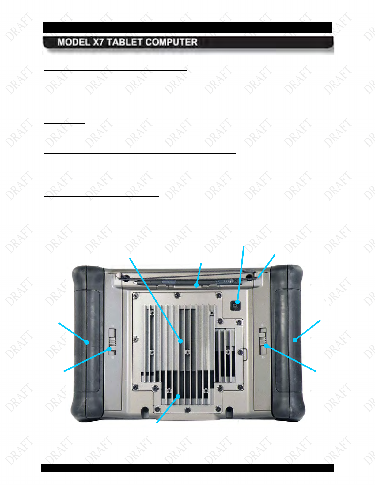
NOTE
Front Panel Features
All references to front/back, top/bottom and left/right are relative
to the face-on view as shown in Figure 2 .
Figure 2. ARMOR X7 Key Features – Front View
FINGERPRINT
SCANNER
DUAL MODE
DISPLAY
WLAN / WWAN / GPS
ANTENNAS
NOISE CANCELLING
MICROPHONES
RIGHT
CONTROL
PANEL
INDICATOR
PANEL
LEFT
CONTROL
PANEL
SPEAKER
SECTION 2 LEARNING ABOUT YOUR ARMOR X7 PAGE 36
9711-26400-0001
EXPORT CONTROLLED – SEE PAGE 3
Rev -
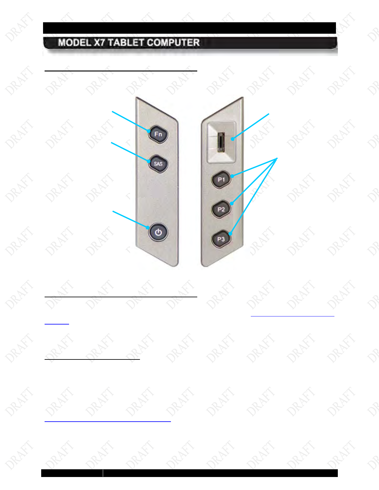
There are 6 momentary contact push buttons and a fingerprint scanner sensor located on two
control panels on either side of the X7 display, as shown in
Left and Right Control Panels
Figure 3.
Figure 3. X7 Control Panels
The PBs can be used to control different functions such as increasing or decreasing brightness
or changing audio volume level with just a single press. Refer to
Programmable Buttons (PBs ) P1, P2, P3
Programmable Button (PB)
Settings for information on how to select available options.
Each programmable button has a built-in LED that lights for approximately 5 seconds when the
button is pressed.
The fingerprint sensor is used with security software to allow you to log onto the computer or
gain access to specific applications. Use of the sensor for reading fingerprints requires
specialized software that is not provided with the X7.
Fingerprint Sensor (FPS)
The sensor can also be used to steer the on-screen pointer and perform some simple mouse
functions. Normally, this requires third-party software that does not come with the X7. However,
we have provided some introductory software that will allow you to explore this feature. Refer to
Using the FPS as a Simple Mouse Device.
FPS SENSOR/
MOUSE
DEVICE
SECURITY
ATTENTION
SEQUENCE
BUTTON
POWER
ON/OFF
BUTTON
FUNCTION (Fn)
BUTTON
PROGRAMMABLE
BUTTONS
SECTION 2 LEARNING ABOUT YOUR ARMOR X7 PAGE 37
9711-26400-0001
EXPORT CONTROLLED – SEE PAGE 3
Rev -
This button is used with programmable buttons P1, P2 and P3 to activate three additional
functions. Press and release the Fn button and then press and release P1, P2 or P3 to activate
the function. Refer to the description of the
Fn (Function) Button
Programmable Button (PB) Settings for information
on how to select available options for each combination.
The Fn button also has a built-in LED that lights for approximately 5 seconds when the button is
pressed.
Pressing this button generates the SAS scan code and invokes the CTRL-ALT-DEL command,
which opens the Windows Task Manager screen.
Security Attention Sequence (SAS) Button
This button is also known as the Windows Security Key Button, the Side Button and the OEM
Button.
The Power button is primarily used to turn the computer on or off, but it also performs other
functions when the computer is running and when the computer is in sleep or hibernate mode,
as detailed in
Power Button
Table 1.
To turn the computer off when in normal operation, use the available Windows shutdown
procedures from the desktop.
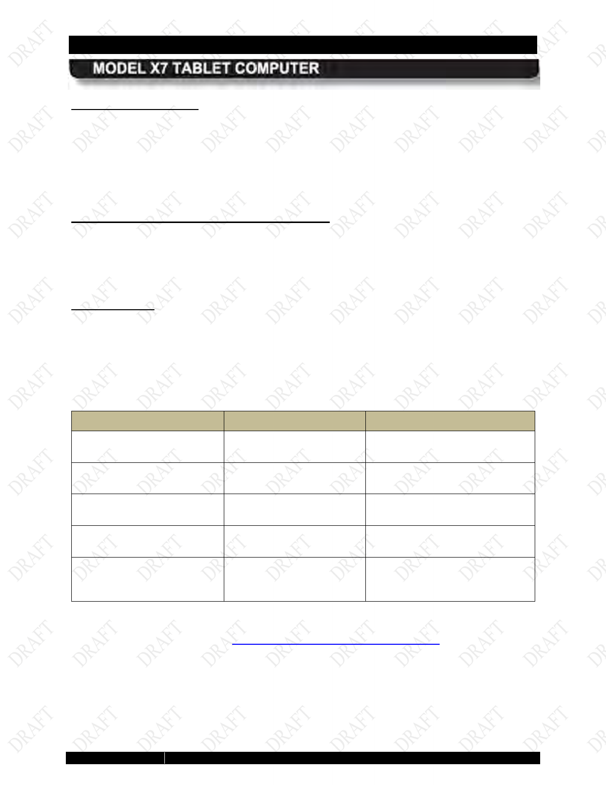
Table 1. Power Button Actions
Operating State
Power Button Action
Result
Computer powered off
Press and hold for at least
1 second and then release
Computer turns on and boots up
into new Windows session.
Computer powered on and
awake Press and release Computer goes into Sleep mode
and saves your current session.
Computer in Sleep mode
(powered on)
Press and release
Computer wakes up and
restores your current session.
Computer in Hibernate mode
(powered off)
Press and release
Computer turns on and restores
your previous session.
Computer powered on
Press and hold for 5 or
more seconds (emergency
shutdown)
Computer shuts down
immediately and does not save
your session.
You can change the default action of the Power button through the Power Options settings in
Windows Control Panel. Refer to Changing the Power Button Default Action
NOTE: This change will affect only the powered-on state; the Power button still works the same
when the computer is powered off or is in sleep or hibernate mode.
.
SECTION 2 LEARNING ABOUT YOUR ARMOR X7 PAGE 38
9711-26400-0001
EXPORT CONTROLLED – SEE PAGE 3
Rev -
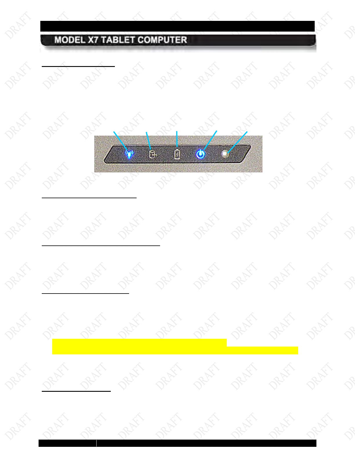
There are 4 LED status indicators located on the indicator panel at the upper right of the X7
display, as shown in
Indicator Panel
Figure 4 (NOTE: The fifth object to the far right on the panel is the ambient
light sensor (ALS), not an LED). The intensity of the status indicators varies as the screen
brightness is varied.
The functions of these indicators are described below.
Figure 4. Indicator Panel
A blue LED that is on whenever the WLAN, WWAN or Bluetooth wireless radio is in transmit
mode (GPS is receive only). The indicator will be on steady whenever your WLAN or WWAN
radio is connected to a network. For Bluetooth, the indicator will only be on when data is being
transmitted to a peripheral such as a printer, scanner or USB hub.
Wireles s Activity Indicator
A blue LED that is on intermittently whenever a storage device is being accessed. Storage
devices can include the 1.8 inch solid-state drive, mSATA drive or an SD memory card, or a
combination of any of these (NOTE: The mSATA drive is an integral part of the X7 circuitry and
is not physically accessible by the user).
Storage Device Activity Indicator
A dual LED that can be amber or red and has the following conditions:
Charging/Fault Indicator
• Off when the computer is off.
• Off when the computer is powered by batteries only and no faults are detected.
• A steady amber color when external power is connected and the batteries are fully
charged.
• Flashing at a 1/2 second rate while batteries are charging.
• Flashing at a 1 second rate when charging has stopped due to battery temperature.
• A steady red color if a power system fault occurs such as an overvoltage, undervoltage
or overcurrent condition or a battery charger or battery internal failure. The red indicator
will turn off when the fault condition is removed.
A blue LED that is on steady whenever power is applied to the ARMOR X7 and is off when
power is shut down.
Power On Indicator
WIRELESS
STORAGE
CHG/FLT
POWER
ALS
SECTION 2 LEARNING ABOUT YOUR ARMOR X7 PAGE 39
9711-26400-0001
EXPORT CONTROLLED – SEE PAGE 3
Rev -
The ALS is located on the indicator panel (see
Ambient Light Sensor (ALS)
Figure 4). It senses changes in surrounding light
levels and adjusts the display brightness and indicator light levels accordingly. If the surrounding
light level increases, the display and indicator brightness will increase proportionally; if the light
level decreases, the display and indicator brightness will decrease proportionally.
A single high-volume speaker is located on the top left of the front panel, as shown in
Speaker
Figure 2.
Two noise-canceling microphones are located at the bottom of the front panel. These
microphones support simultaneous analog and 4-channel digital recording.
Noise Cancelling Stereo Microphones
The rear panel of the X7 houses a built-in webcam, a cooling register, bays for two batteries and
a compartment that provides access to installed radio modules, a SIM card socket, and a micro
SD socket. A slot for the active pen is also built into the back panel with posts to secure the
lanyard.
Rear Panel Features
REAR COMPARTMENT
(BEHIND COOLING
REGISTER)
BATTERY
#2
COOLING
REGISTER
BATTERY
#1
WEBCAM
ACTIVE
PEN WITH
LANYARD
BATTERY
RELEASE
BUTTON
BATTERY
RELEASE
BUTTON
LANYARD
POST (X2)

SECTION 2 LEARNING ABOUT YOUR ARMOR X7 PAGE 40
9711-26400-0001
EXPORT CONTROLLED – SEE PAGE 3
Rev -
Figure 5. Key Features - Rear Panel
ARMOR computers are designed to operate in dirty and moist environments under extreme
temperatures. Because the tablet is sealed against contamination, the X7 incorporates passive
cooling which channels the internal heat to the cooling register at the back of the unit. The
register dissipates the heat evenly and feels only mildly warm to the touch.
Cooling Regis ter
The cooling register also acts as a cover for a sealed compartment which provides access to
the solid-state drive (if installed), a SIM card socket and a micro-SD socket.
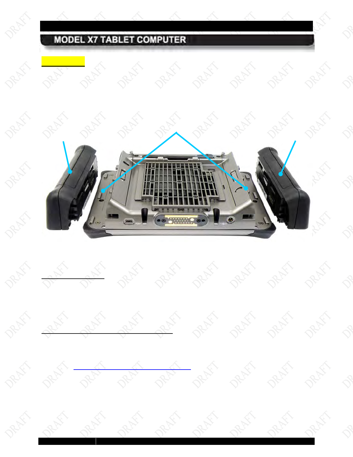
SECTION 2 LEARNING ABOUT YOUR ARMOR X7 PAGE 41
9711-26400-0001
EXPORT CONTROLLED – SEE PAGE 3
Rev -
Your X7 is shipped with two batteries that are installed in bays on either side of the X7, as
shown in
Batteries
Figure 6. These batteries are high efficiency lithium-ion batteries that are “hot
swappable.” That is, if you have two batteries installed, you can replace one battery while the
computer operates on the other battery. With this capability, you do not have to shut down the
computer or interrupt your current operating session in order to replace a battery.
Figure 6. X7 Battery Bays
Your X7 batteries have built-in “smart” technology to monitor their charging functions and
internal conditions. These batteries are self-calibrating and self-regulating. Should a problem
occur, even a short circuit, the X7 battery will disconnect itself from the computer to prevent any
damage. Since the batteries are literally the handles for the X7, you can keep a defective
battery in place until you obtain a replacement.
“Smart Batteries”
Depending on your purchase, your X7 came with one or two 2-cell or 4-cell batteries. The 2-cell
battery has a capacity of 2850 mAh battery and the 4-cell battery has a capacity of 5900 mAh
battery.
Two Battery Capacities are Available
Table 33. Summary of X7 Battery Operating Times lists the operating and charging times for
both types.
BATTERY #1
BATTERY
BAYS
BATTERY #2
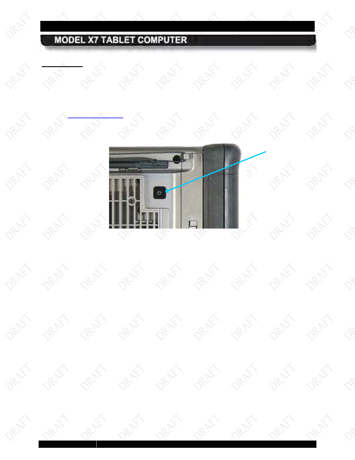
SECTION 2 LEARNING ABOUT YOUR ARMOR X7 PAGE 42
9711-26400-0001
EXPORT CONTROLLED – SEE PAGE 3
Rev -
Your X7 has a built-in 2 megapixel camera located on the back side of the unit (see
Webcam
Figure 7).
The camera is equipped with an autofocus lens and can be used to capture still images or
movies, or to scan barcodes. The camera saves still images in JPEG format at 1280 x 1024,
800 x 600 and 640 x 480 pixel resolutions. Movies are saved in Windows Media Video (.wmv)
format.
Refer to Using the Webcam for instructions on capturing still images and video and scanning
bar codes.
Figure 7. X7 Webcam
WEBCAM
LENS
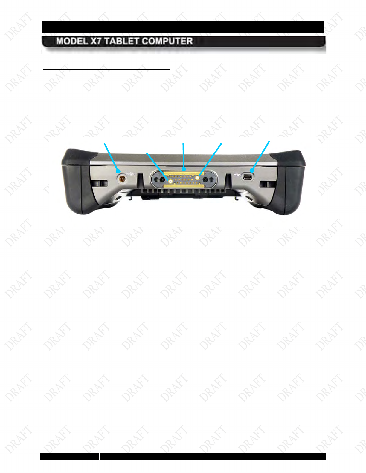
SECTION 2 LEARNING ABOUT YOUR ARMOR X7 PAGE 43
9711-26400-0001
EXPORT CONTROLLED – SEE PAGE 3
Rev -
The bottom panel houses an AC adapter jack, a mini-USB connector and a 20-pin docking
connector. The docking connector contains two RF ports to connect the X7 to external GPS and
wireless antennas.
Bottom Panel Features
Figure 8. Key Features – Bottom Panel
AC ADAPTER
JACK
DOCKING
CONNECTOR
MINI USB
CONNECTOR
GPS
ANTENNA
WIRELESS
ANTENNA
CONNECTOR
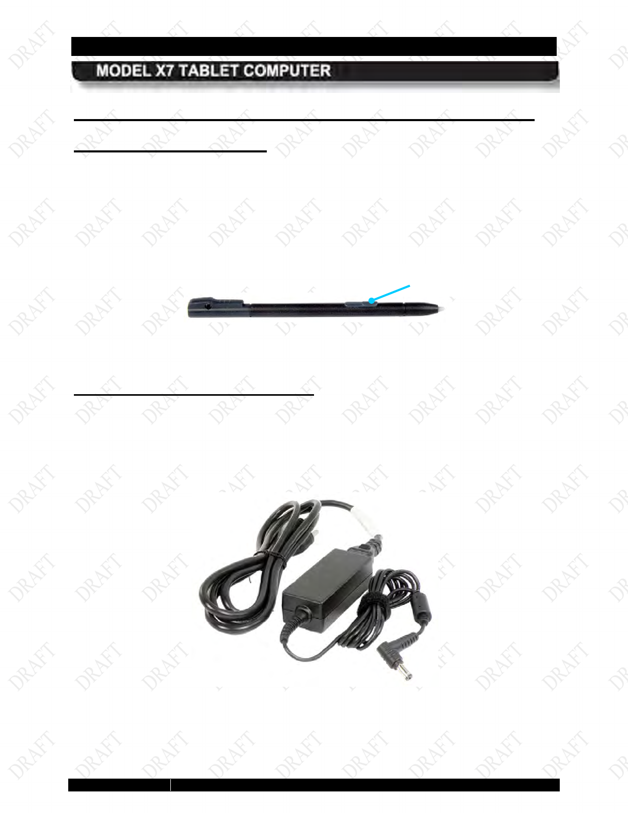
SECTION 2 LEARNING ABOUT YOUR ARMOR X7 PAGE 44
9711-26400-0001
EXPORT CONTROLLED – SEE PAGE 3
Rev -
Included Components, Accessories and Support
The pen that comes with your X7 (
Active Pen with Tether
Figure 9) has circuitry in the tip that interacts with the digitizer
assembly built into the tablet display. The digitizer detects the pen tip close to the screen and
activates certain functions like steering the pointer or performing a right click action if the pen is
allowed to hover for a few seconds.
The pen also has a side button that can be programmed for a number of different functions
(refer to the Pen Tablet Properties Utility). It’s default function is Right-Click. The pen is stored
in the tablet’s carrying handle and is secured to the handle by a flexible tether.
Figure 9. The ARMOR X7 Pen
Included with your ARMOR X7 is a +19 VDC ± 5%, 2 amp AC power adapter, or “AC Adapter”.
This external DC power supply can be plugged in to any 100-240 VAC standard 3-prong outlet
and is used to recharge your computer’s batteries and provide power to the computer without
draining the batteries. A North American power cord is standard, but a European AC power cord
is also available.
AC Adapter and Power Cord
Figure 10. ARMOR X7 AC Adapter
SIDE BUTTON
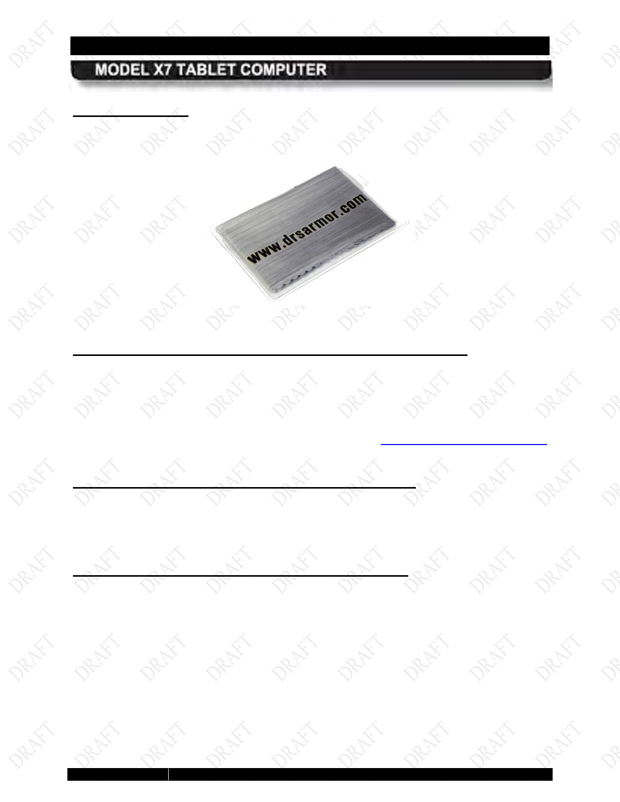
SECTION 2 LEARNING ABOUT YOUR ARMOR X7 PAGE 45
9711-26400-0001
EXPORT CONTROLLED – SEE PAGE 3
Rev -
This microfiber cloth is specially designed to clean the display screen of dust and fingerprints.
See for important information about using this cloth with the X7 display.
ARMOR Cloth
Figure 11. ARMOR Microfiber Cleaning Cloth
The X7 is equipped with a SIM card socket as required by GSM networks. A SIM card is a
small electronic card that contains your GSM subscriber ID, billing information, and network
permissions (see . The card allows you to easily transport your subscriber information to
another computer or subscriber device.
Subscriber Identity Module (SIM) Card Support
You must have a SIM card installed in order to use your Gobi radio to connect to a GSM WWAN
network. For instructions on installing your SIM card, see Installing the Subscriber Identity
in the Networking section.
Module (SIM
The ARMOR X7 also provides a card reader for a micro SD or SDHC card. These cards are
used as removable flash memory. The micro SD card slot is located inside the rear
compartment, as shown in
Secure Digital (SD) Card Reader Support
Figure 76. The Windows operating system recognizes the card as a
removable drive, just like a USB memory stick.
The X7 supports the Infineon SLB 9635 TPM controller module. This module meets the
requirements of the Trusted Computing Group (TCG) Trusted Platform Module Specification
1.2. The TPM module is connected to the low pin count (LPC) bus.
Trusted Platform Module (TPM) Support
For more information on TPM capabilities with the ARMOR X7, contact DRS Tactical Systems,
Inc. toll free at 1-800-872-1100.
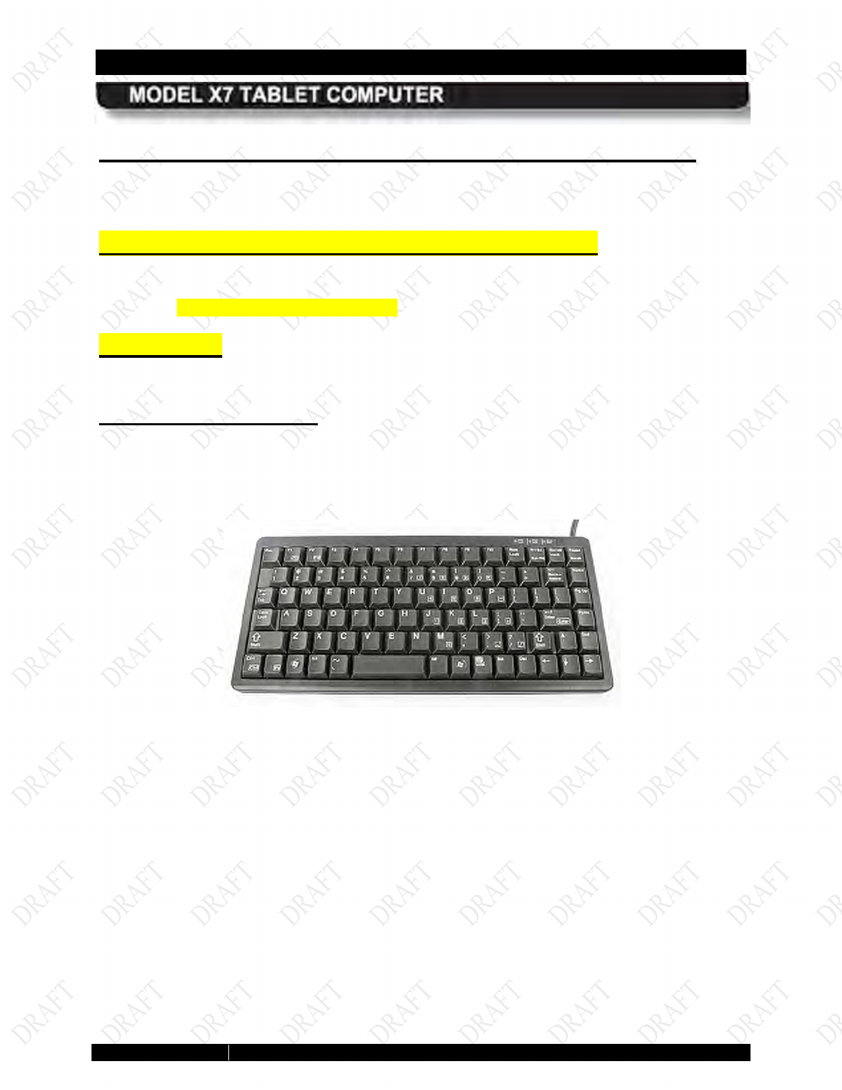
SECTION 2 LEARNING ABOUT YOUR ARMOR X7 PAGE 46
9711-26400-0001
EXPORT CONTROLLED – SEE PAGE 3
Rev -
There are a number of optional add-ons and accessories that extend the capabilities of the X7
or make it easier to use.
Optional Add-ons and Accessories for Your X7
DRS offers the Gobi® WWAN radio for use with the X7 computer. This wireless radio allows you
to surf the internet, check email and connect to a Virtual Private Network (VPN) using cell phone
technology just about anywhere in the world.
Wireles s Wide Area Network (WWAN) Radio
The U-Blox GPS receiver is available as an add-on.
GPS Radio
A reduced-size USB keyboard (
Compact Keyboard
Figure 12) is available for use with the ARMOR X7 computer.
The keyboard is approximately half the size of a standard keyboard and can be connected
directly to the X7 or to a desk docking station to conserve space on a table or desktop.
Figure 12. Compact Keyboard
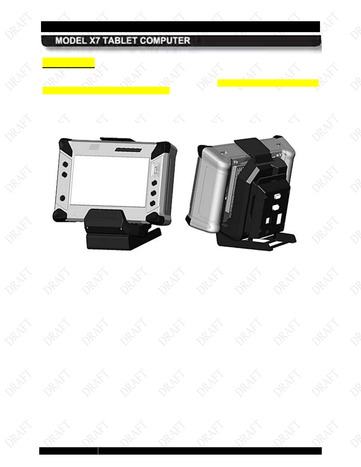
SECTION 2 LEARNING ABOUT YOUR ARMOR X7 PAGE 47
9711-26400-0001
EXPORT CONTROLLED – SEE PAGE 3
Rev -
The X7 desk dock is designed to fit on your desktop without taking up a lot of space. It is made
of light-weight but rugged plastic and houses connectors for 3 USB ports, 2 GPIO ports, an RS-
232 serial port and 5 VDC external power. The X7 slips easily into the cradle and locks into
place with the spring-loaded top clamp. Just lift up on the clamp slightly to release the tablet.
Des k Dock
Figure 13. X7 Desk Dock
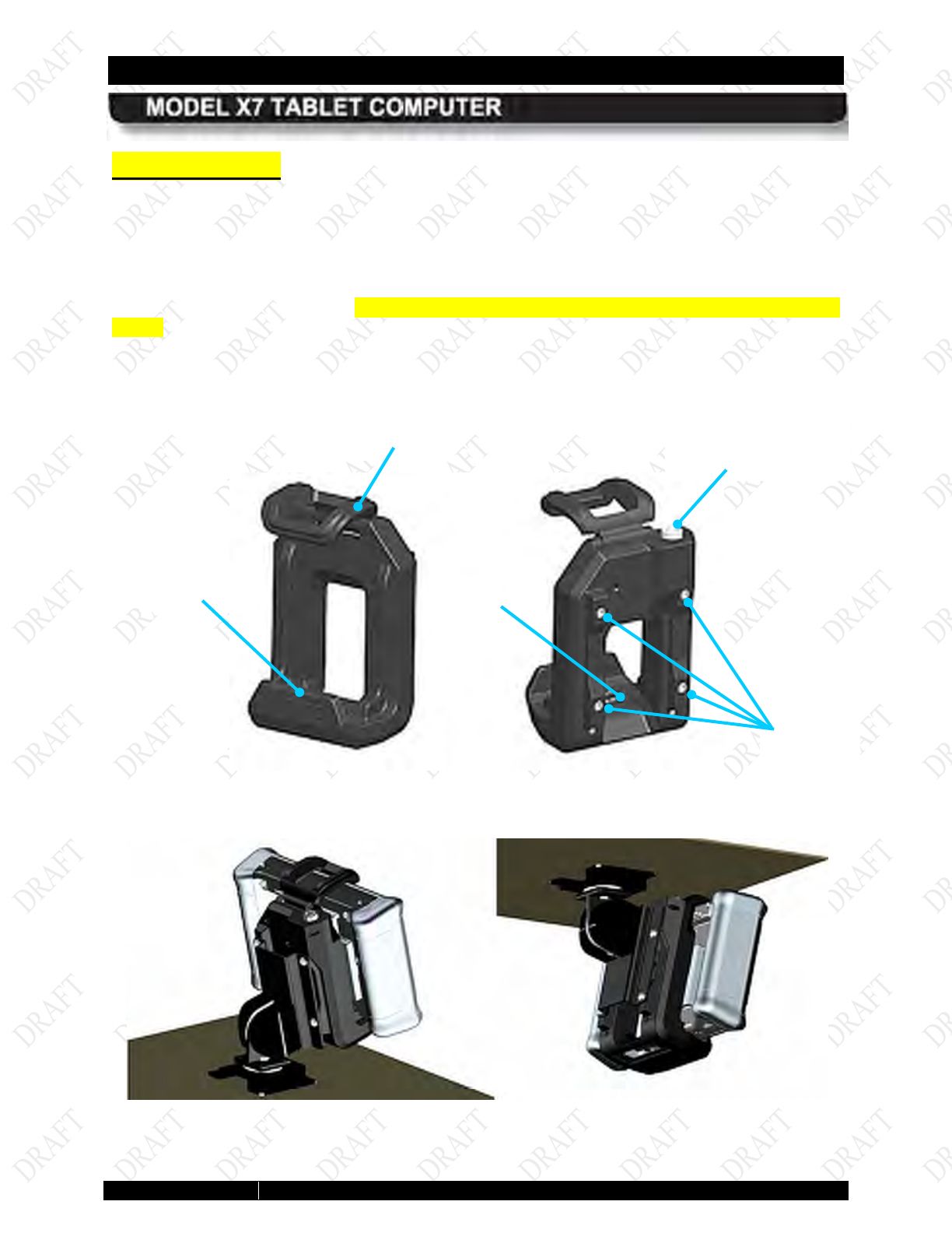
SECTION 2 LEARNING ABOUT YOUR ARMOR X7 PAGE 48
9711-26400-0001
EXPORT CONTROLLED – SEE PAGE 3
Rev -
The X7 dock is made of UV-resistant high-impact plastic that weighs less than 2 lbs. It is
designed to be attached to any mount that accepts the Video Electronics Standards Association
(VESA) 75 mm hole pattern. The dock has a latch mechanism that can withstand over 50,000
latch/unlatch cycles and the latch can be locked with a key to prevent tablet removal. The
floating docking connector is field-replaceable.
Vehicle Dock
The dock has connections for 3 USB ports, 2 bi-directional GPIO ports and external 5 VDC
power. The tablet slips easily into the cradle and can be inserted and latched with one hand.
The X7 vehicle dock is rugged and light weight and can be adapted to just about any mounting
situation from console and dashboard installation to bulkhead and cab roof installation (see
Figure 15), or it can be floor mounted using a special mounting assembly.
Figure 14. X7 Vehicle Dock
Figure 15. Examples of X7 Vehicle Dock Mounting Configurations
LATCH
LATCH/UNLATCH
BUTTON
75 MM
VESA
HOLE
PATTER
CRADLE
FLOATING
DOCKING
CONNECTOR
CONSOL
E MOUNT
ROOF
MOUNT
FINGERPRINT
SENSOR (FPS)
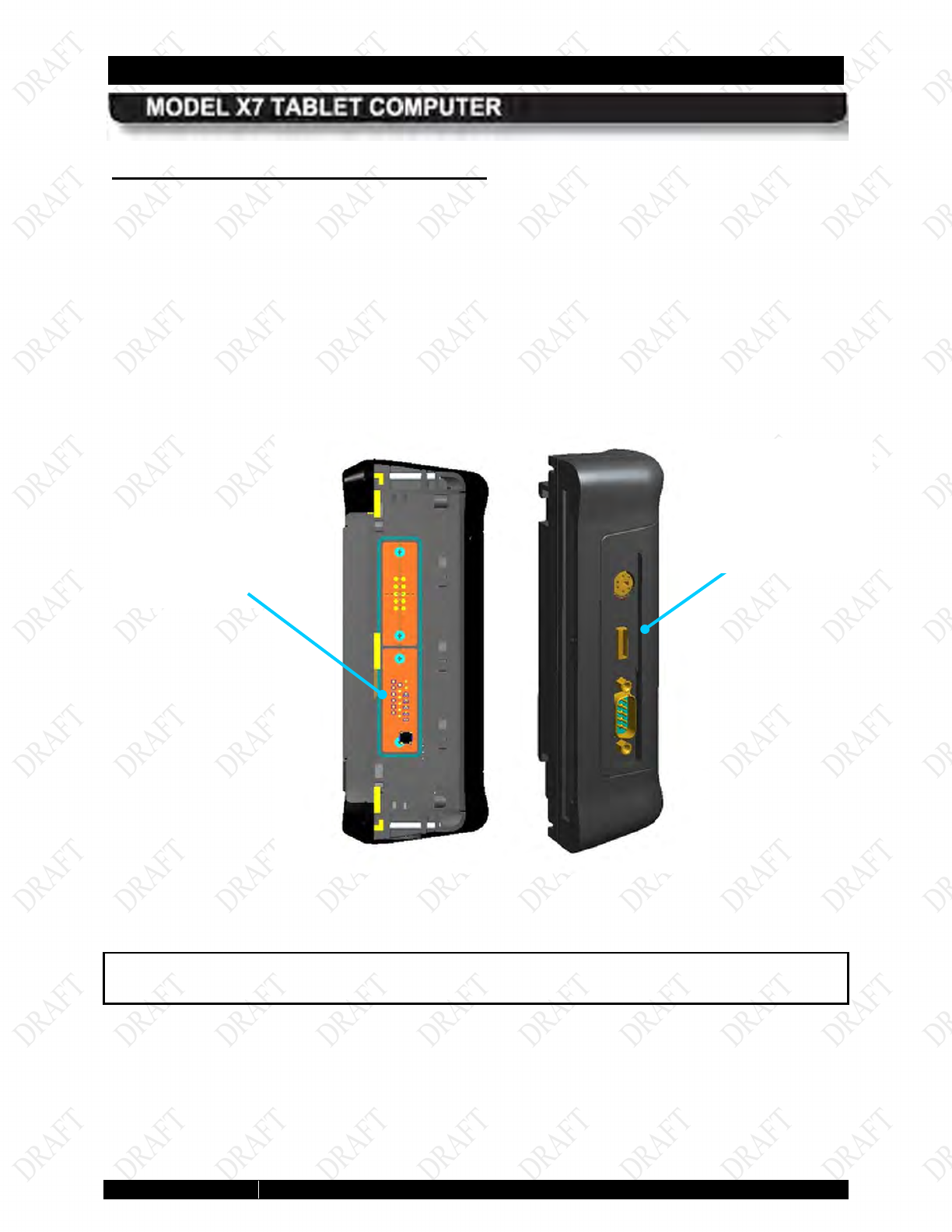
SECTION 2 LEARNING ABOUT YOUR ARMOR X7 PAGE 49
9711-26400-0001
EXPORT CONTROLLED – SEE PAGE 3
Rev -
The X7 computer provides additional space and a flexible I/O connectivity to accommodate a
custom card or module such as a radio frequency ID (RFID) tag reader, contactless card reader
or satellite communications module. It can also be used to provide additional interface ports.
ARMOR Flexspace™ Adapter
The X7 Flexspace consists of a battery-shaped adapter that replaces the right-side battery.
Figure 16 shows a conceptual model of a Flexspace adapter that provides additional interface
connectors.
For more information on Flexspace capabilities with the ARMOR X7, contact DRS Tactical
Systems, Inc. toll free at 1-800-872-1100.
Figure 16. ARMOR X7 Flexspace™ Adapter Concept
For information on these and any other ARMOR X7 accessories, please contact your
ARMOR sales representative or call DRS Tactical Systems toll free at 1-888-872-1100.
FLEXSPACE
INTERFACE
CONNECTOR
EXAMPLE OF
FLEXSPACE
ADAPTER WITH
ADDITIONAL
CONNECTORS

SECTION 2 LEARNING ABOUT YOUR ARMOR X7 PAGE 50
9711-26400-0001
EXPORT CONTROLLED – SEE PAGE 3
Rev -
This Page Intentionally Left Blank
SECTION 3 GETTING STARTED PAGE 51
9711-26400-0001
EXPORT CONTROLLED – SEE PAGE 3
Rev -
3. GETTING STARTED
The information in this section will help you get your X7 set up and operating. Please read all
warnings, cautions and notes prior to each procedure or step.
CAUTION!
Use this product only in vehicles with a regulated voltage supply of
+10 to +30 VDC. Voltages outside this range could cause unstable
operation or result in permanent damage to the computer.
CAUTION!
Use only the external AC Adapter provided with your ARMOR X7 or
an equivalent model approved by DRS
. Attempting to use a
different model power supply could result in equipment damage.
CAUTION!
DO NOT
connect the computer to more than one power source at a
time (such as to both an AC adapter and docking station) or
permanent damage to the battery and/or computer may result.
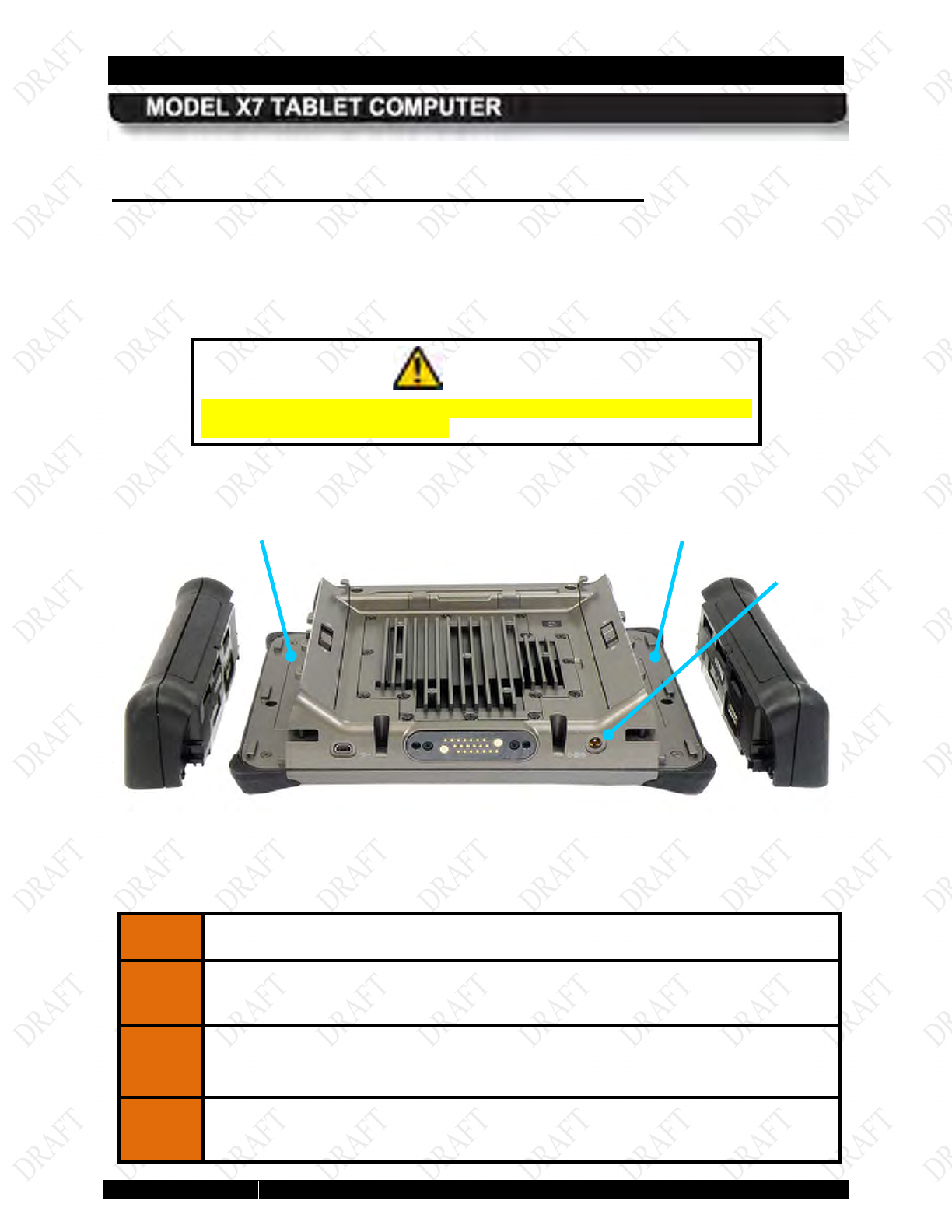
SECTION 3 GETTING STARTED PAGE 52
9711-26400-0001
EXPORT CONTROLLED – SEE PAGE 3
Rev -
The first step to getting your X7 operating is to install and charge the batteries. The batteries are
inserted into slots or “bays” on side of the computer as shown in
Installing and Charging the Batteries
Figure 17. The batteries are
identical and can be installed in either bay. Follow the procedure in Table 2 to install the
batteries.
CAUTION!
When using the provided AC adapter, the maximum safe ambient
operating temperature is 40°C.
Figure 17. X7 Batteries Positioned for Installation
Table 2. Install the X7 Batteries
STEP ACTION
1.
Place the flat surface of the first battery on the left side compartment tray with the
locking slots facing toward the computer.
2.
Push and hold the battery latch and slide the battery toward the computer until
the locking bar engages and the battery is flush against the compartment wall.
Rock the battery slightly if necessary to engage the locking bar.
3.
Release the battery latch to lock the battery in place.
BATTERY #1
BAY
BATTERY #2
BAY
AC
ADAPTE
R
C
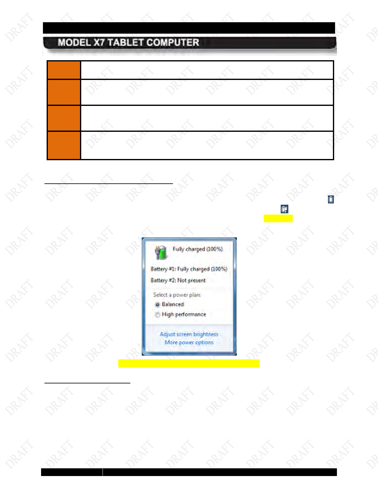
SECTION 3 GETTING STARTED PAGE 53
9711-26400-0001
EXPORT CONTROLLED – SEE PAGE 3
Rev -
STEP ACTION
4. Perform steps 1-3 to install the second battery.
5. Connect the AC adapter to the jack on the bottom of the X7 and plug the adapter
power cord into an AC outlet.
6. Allow the batteries to charge until the Charge/Fault indicator turns off. This could
take anywhere from 2 to 4 hours depending on the level of charge when the
batteries were received. You can work with your X7 while the batteries charge.
You can check the current charge level of your batteries at any time by clicking on the battery
icon in the system tray on the Windows desktop. This icon will have the shape of a battery
when the unit is operating on batteries alone, and will have a plug next to it when external
power is applied. Clicking on this icon opens a window like that shown in
Monitoring Battery Charge Levels
Figure 18.
Figure 18. System Tray Battery Window
A multi-LED battery charge indicator, or “fuel gauge”, is located on each battery pack, as shown
in
Battery “Fuel Gauges”
Figure 19. Each LED array consists of 5 LEDs and each LED represents 20% of the total
charge of the battery as follows:
LED #5 - 81-100% (far right LED)
LED #4 - 61-80%
LED #3 - 41-60%
LED #2 - 21-40%
LED #1 - 01-20% (far left LED)
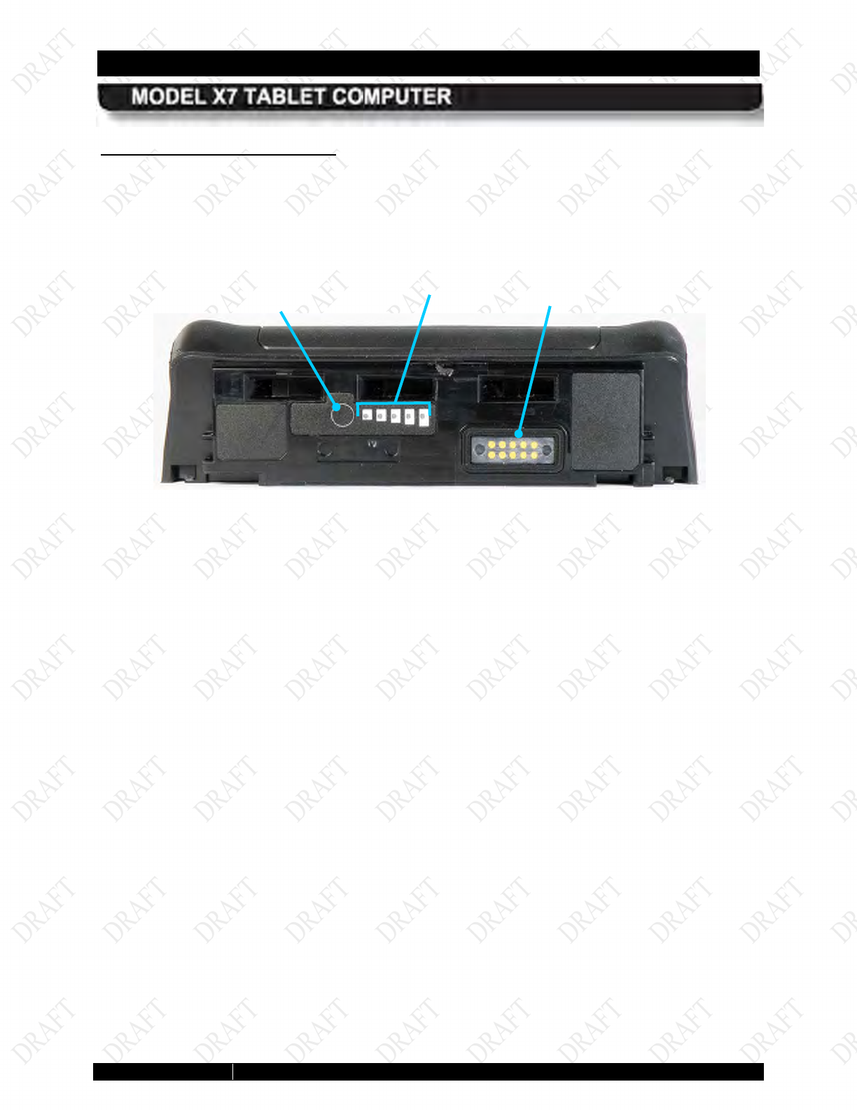
SECTION 3 GETTING STARTED PAGE 54
9711-26400-0001
EXPORT CONTROLLED – SEE PAGE 3
Rev -
The fuel gauge indicators are not visible when the battery is installed. However, when a battery
is disconnected, you can press the battery button to activate the fuel gauge and check the
current charge level.
Activating the Fuel Gauges
Figure 19. Battery Fuel Gauge
FUEL GAUGE
BUTTON FUEL GAUGE
1 2 3 4 5
BATTERY
CONNECTOR
SECTION 3 GETTING STARTED PAGE 55
9711-26400-0001
EXPORT CONTROLLED – SEE PAGE 3
Rev -
On the left control panel, press and hold the Power button for at least 1 second and then
release. If this is the first time the computer has been started since you received it, the Microsoft
Out-of-Box Experience (OOBE) setup instructions will appear after the computer boots up.
Follow these instructions to configure your Windows operating system software.
Turning On Your X7 for the First Time
Turn the computer on by pressing the Power button for at least 1 second and then releasing it.
The ARMOR X7 will perform self-checking routines during the start-up process. All units are
configured at the factory to automatically boot to the Microsoft Windows desktop unless a
custom configuration has been requested.
Turning the Computer On Normally
To put the tablet into sleep mode, press and release the Power button while the tablet is
operating. NOTE: This is the default action of the Power button when you first receive your X7,
but this can be changed in Windows Control Panel (see
Putting the Computer in Sleep Mode
Changing the Power Button Default
Action instructions).
You can also put the computer to sleep from the Windows desktop. Click on the Start button
and click the down arrow next to the Shut Down button, then select Sleep.
When the computer is in sleep mode, the screen will be dark and all LED will be off except the
battery status indicator. This LED will flash at a 1 sec rate to indicate the computer is in sleep
mode. The computer will continue to run normally in the background and your session will be
held in suspension.
Press and release the Power button again to wake up the computer and return to your session.
To turn the computer off normally, select Start à Shut down from the Windows desktop. The
computer will perform a normal shutdown.
Turning the Computer Off Normally
NOTE
Do not press and release the Power button to turn off the computer. This will
only put the computer into sleep mode and the screen will go dark. This
could be mistaken for a power off condition while the computer is actually
still running and consuming battery power.
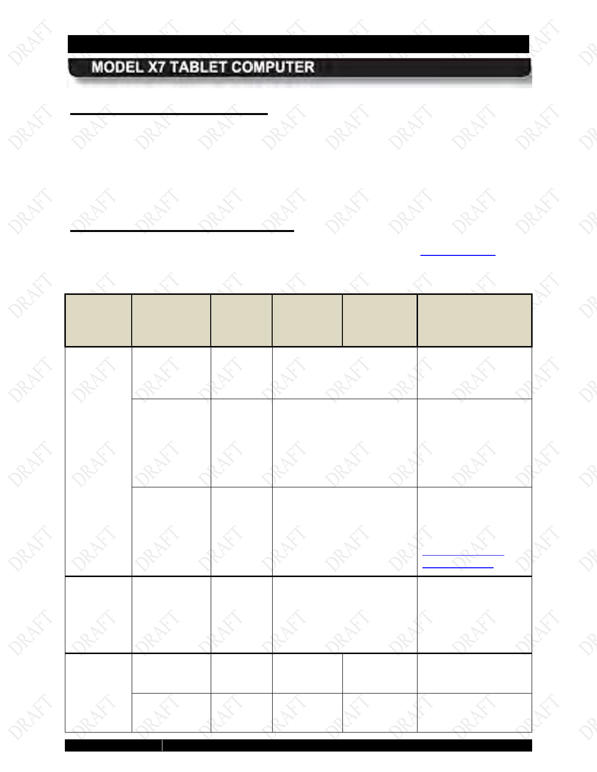
SECTION 3 GETTING STARTED PAGE 56
9711-26400-0001
EXPORT CONTROLLED – SEE PAGE 3
Rev -
If an emergency condition occurs where the computer needs to be shut down immediately,
press and hold the Power button for more than five seconds. The computer will bypass the
normal Windows shutdown sequence and turn off.
Emergency Shutdown
This procedure should only be used in emergencies because improperly shutting down
Windows may result in the loss of data and possible corruption of the operating system.
Table 3
Indicator State Summary
lists all states for the various X7 indicator LEDs (refer to Indicator Panel for a
description of each indicator).
Table 3. X7 Indicator State Summary
LED IF THE
INDICATION
IS:
AND THE
POWER
MODE IS:
AND
EXTERNAL
POWER IS:
AND
BATTERY
IS:
THIS MEANS:
Wireless
(blue) On On Either At least one radio is
transmitting (GPS is
receive only).
Flashing
intermittently On Either The WLAN or WWAN
radio is searching for
a network connection
or Bluetooth is
transmitting data to a
peripheral.
Off On Either One or more installed
radios (excluding
GPS) are disabled in
ARMORutils. See
Wireless Devices
Dialog Window.
Storage
Activity
(blue)
Flashing
intermittently Power on Either Processor is
accessing a storage
device (SSHD,
mSATA memory or
micro SD card).
Charging/
Fault
(amber or
red)
Off Power on Disconnecte
d Installed No power faults are
detected
Off Power off Connected Installed Batteries are not
charging
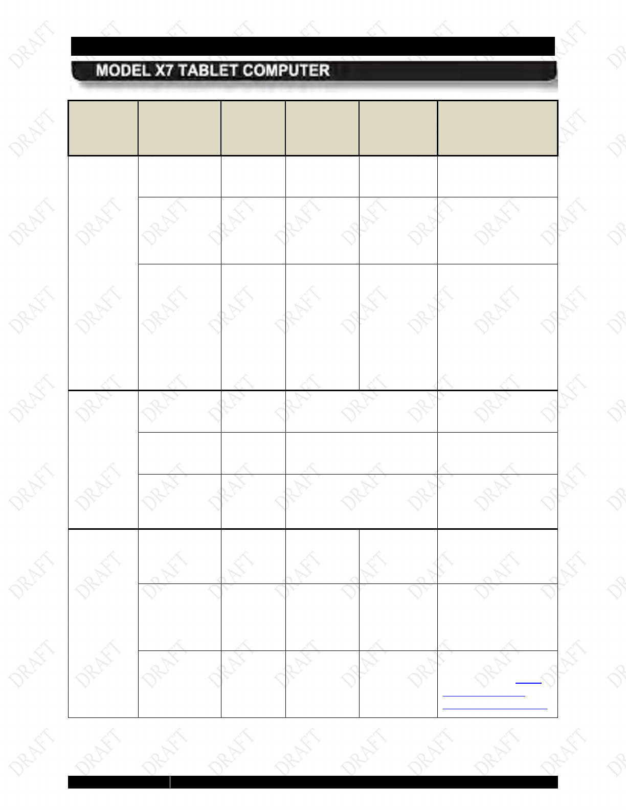
SECTION 3 GETTING STARTED PAGE 57
9711-26400-0001
EXPORT CONTROLLED – SEE PAGE 3
Rev -
LED IF THE
INDICATION
IS:
AND THE
POWER
MODE IS:
AND
EXTERNAL
POWER IS:
AND
BATTERY
IS:
THIS MEANS:
Flashing at 1
sec rate Power
on/off Connected Installed Batteries are
charging
Flashing
amber at 1/2
sec rate
Power
on/off Connected Installed Battery charging has
stopped due to
extreme battery
temperature
On steady red Power
on/off Connected Installed Power system fault
(overvoltage,
undervoltage or
overcurrent condition
or battery failure).
The LED will turn off
when the fault
condition is removed.
Power
(blue) On On Either Computer is powered
up.
Flashing Reduced Either Computer is in sleep
mode.
Off Off Either Computer is powered
off or in hibernate
mode.
Fuel
Gauge
(blue)
NOTE:
press fuel
gauge
button to
see
indications
Single LED
on steady N/A N/A Removed Total charge is
maximum for that
level (20%, 40% etc.)
LED # 1 (far
left) flashing
at 1 second
rate
N/A N/A Removed Battery is below 10%
charge level (fully
depleted)
All LEDs off N/A N/A Removed Battery is overly
depleted. See What
to Do for Overly-
Discharged Batteries.
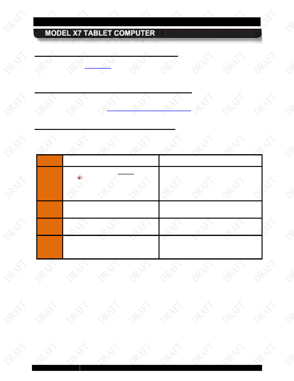
SECTION 3 GETTING STARTED PAGE 58
9711-26400-0001
EXPORT CONTROLLED – SEE PAGE 3
Rev -
Refer to Section 4,
Activating your Wireless Radios
Networking for instructions on activating and using your wireless radio
connections.
The micro SD/SDHC card socket is located inside the rear compartment. For instructions on
how to install the card, refer to
Installing a Micro SD or SDHC Card
Installing a Micro SD or SDHC Card.
Configuring your Audio System
Table 4. Configuring Your Speaker
STEP ACTION CONDITION OR INDICATION
1. Double-click on the orange The Realtek® HD Audio Manager window
opens with the Speakers main tab (top of
page) open and the Speaker
Configuration sub-
tab displayed, as
shown in
speaker
icon in the task bar tray.
Figure 20
2.
Adjust your speaker/headset volumes
as desired.
3. Select the Sound Effects sub-
tab to
select special effects.
4.
Select the Default Format sub-tab to
choose your default sound format.
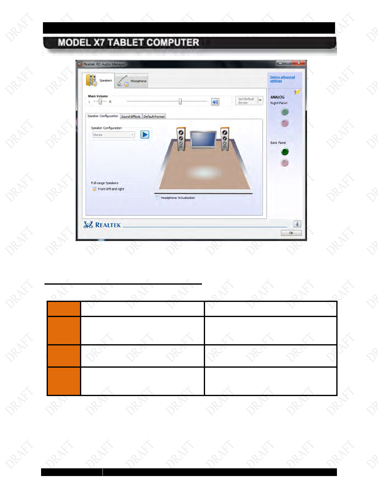
SECTION 3 GETTING STARTED PAGE 59
9711-26400-0001
EXPORT CONTROLLED – SEE PAGE 3
Rev -
.
Figure 20. Realtek HD Audio Manager - Speakers Main Tab
Table 5. Configuring your Microphones
Configuring your Microphones
STEP ACTION CONDITION OR INDICATION
1. Click on the Microphone main tab at
the top of the page. The Microphone main tab opens with the
Microphone Effects sub-
tab displayed,
as shown in Figure 21.
2.
Set up and adjust your microphones.
3. Click on the Default Format sub-tab
to select a default sound format for
your microphones.
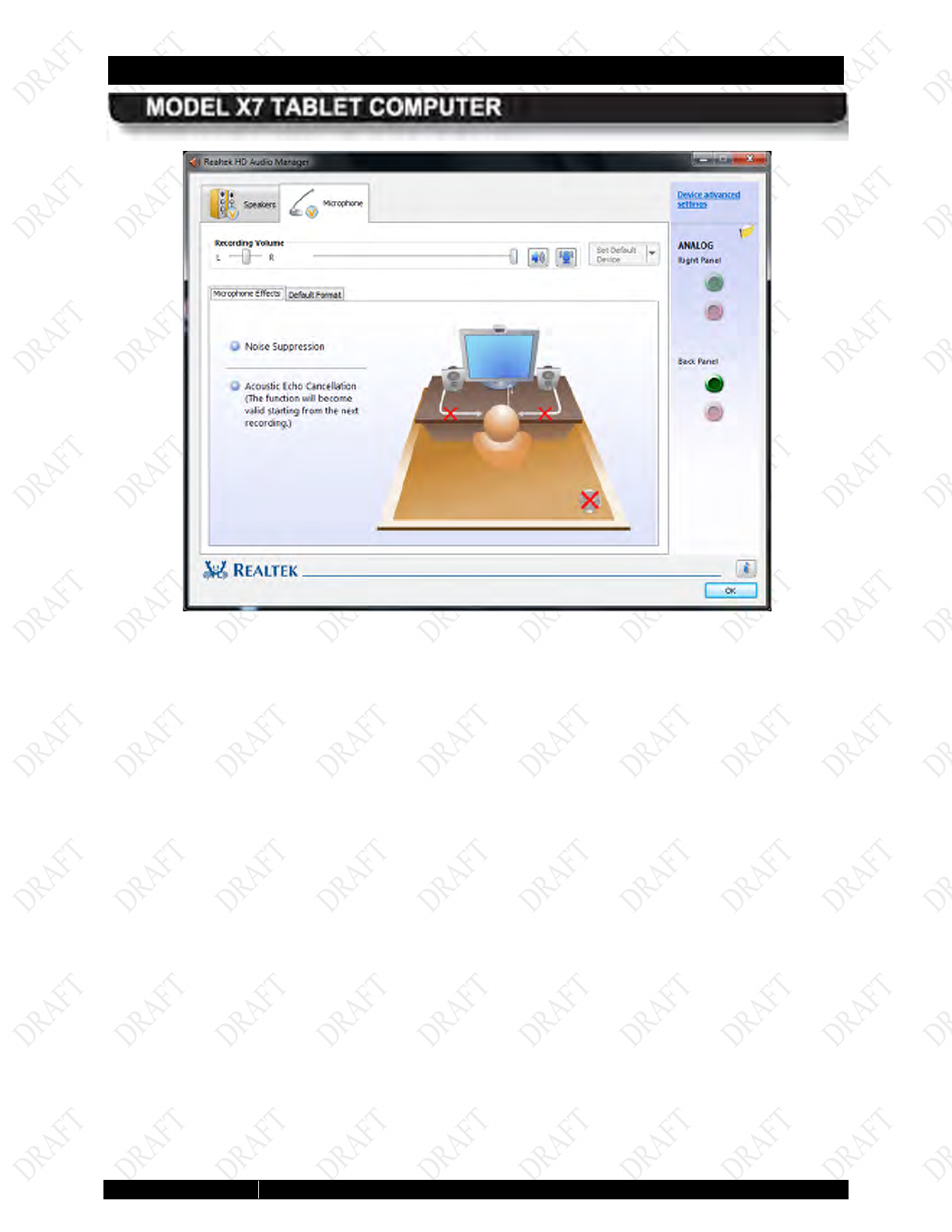
SECTION 3 GETTING STARTED PAGE 60
9711-26400-0001
EXPORT CONTROLLED – SEE PAGE 3
Rev -
Figure 21. Microphone Main Tab
SECTION 3 GETTING STARTED PAGE 61
9711-26400-0001
EXPORT CONTROLLED – SEE PAGE 3
Rev -
Operating the X7 Display
The brightness of an LCD display is controlled by adjusting the intensity of the backlight. The
backlight intensity level for the X7 can be controlled manually or automatically.
Adjusting the Screen Brightness
Your ARMOR X7 Tablet Computer is pre-set for manual adjustment of screen brightness
(backlight level). The brightness can be adjusted manually in two ways: by repeatedly pressing
P1 or P2 on the right control panel or by using the Backlight Setup dialog window in
ARMORutils.
Manual Brightness Adjustment
When you first receive your X7, the P1 button is programmed to increase the screen
brightness in 10% steps, P2 is programmed to decrease brightness in 10% steps and P3 is
programmed to toggle the screen off and on.
Using P1, P2 and P3
Press and release the P1 button repeatedly to increase the brightness to its maximum
level (100%); press the P2 button repeatedly to decrease the brightness to its minimum
level (10%). Press the P3 button to turn the screen completely off; press it again to turn the
screen back on to it’s previously set level.
Double-click on the ARMORutils desktop icon and select the Backlight Setup button. The
Backlight Setup dialog opens as shown in
Using the ARMORutils Backlight Setup Page
Figure 22.
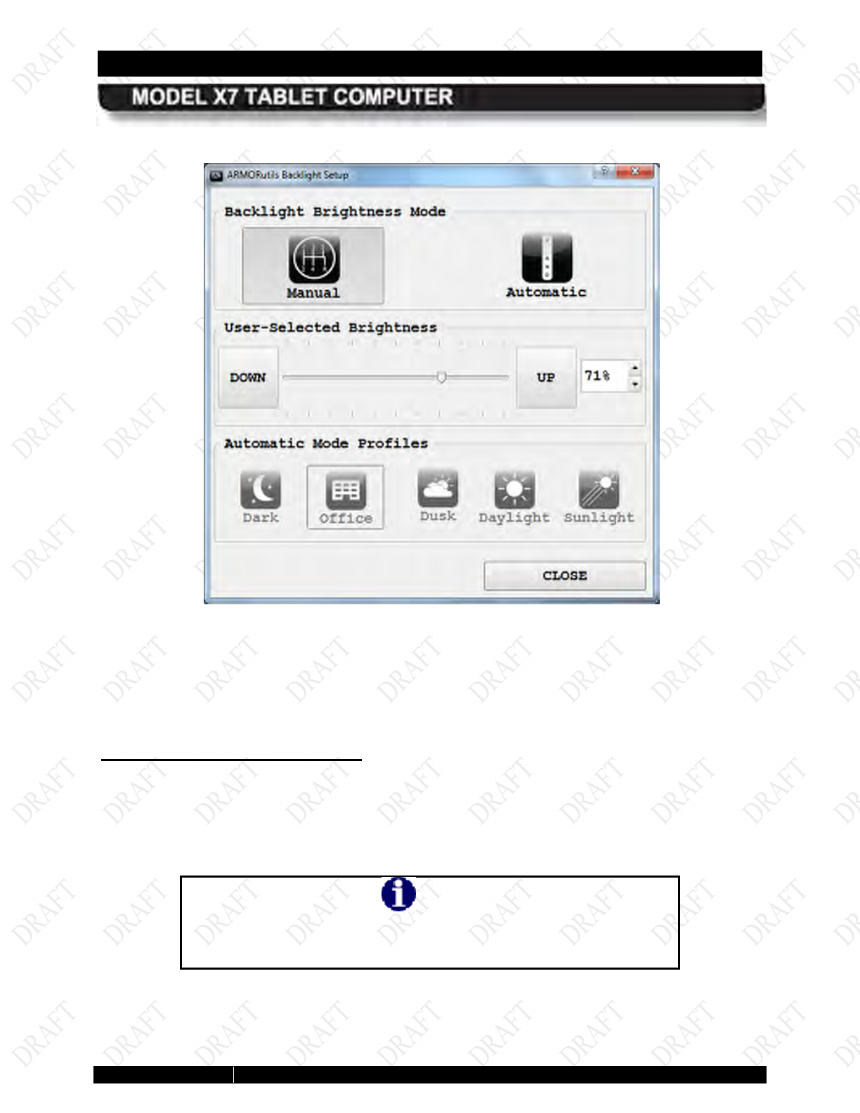
SECTION 3 GETTING STARTED PAGE 62
9711-26400-0001
EXPORT CONTROLLED – SEE PAGE 3
Rev -
Figure 22. Armor Utilities Screen – Backlight Tab
Drag the slider or press the UP or DOWN buttons repeatedly with the pen or a fingertip to
move the slider and adjust the backlight level. The % brightness is displayed in a field on
the right. You can also use the up and down arrows next to this field to adjust the slider.
Open the Backlight Setup dialog in ARMORutils and click on the Automatic button. The
backlight level will now be controlled by the ambient light sensor (ALS). If the surrounding light
decreases, the brightness will also decrease proportionally; if the surrounding light increases,
the brightness will increase proportionally.
Automatic Adjustment
NOTE
You must keep the ALS uncovered to allow proper automatic
brightness adjustment.

SECTION 3 GETTING STARTED PAGE 63
9711-26400-0001
EXPORT CONTROLLED – SEE PAGE 3
Rev -
Everyone’s eyes react differently to changes in light levels and there may be times when the full
range of automatic brightness adjustment is uncomfortable for you.
Automatic Mode Profiles
You can tailor the automatic brightness adjustment by selecting one of the 5 pre-configured
brightness profiles. DRS has researched typical lighting environments and has created these
adjustment profiles that respond more precisely to changing light levels within a particular
environment.
For example, if the automatic brightness doesn’t keep the display bright enough for you under
surrounding lighting conditions, you can select the Dusk, Daylight or Sunlight profile to increase
the brightness range proportionally. Similarly, if the normal brightness control results in light
levels that are consistently too bright, you can select the Office or Dark profile to reduce the
brightness range.
SECTION 3 GETTING STARTED PAGE 64
9711-26400-0001
EXPORT CONTROLLED – SEE PAGE 3
Rev -
When the pen screen is active, you can steer the pointer and perform many functions by simply
hovering close to the screen without actually touching it. Other functions are initiated by
pressing the tip to the screen surface to activate the tip switch or by pressing the side button
switch.
Working with the Pen Screen
The pen that comes with your X7 (
Yo u r X7 Active Pen
Figure 9) is stored in a slot on the back panel (see Figure 5)
and has circuitry that interacts with the digitizer assembly built into the pen screen. The digitizer
detects the pen tip close to the screen and activates certain functions like steering the pointer or
performing a right click action if the pen is allowed to hover for a few seconds. Pressing the tip
to the screen activates a tip switch that performs a left-click action.
Table 6
Using the X7 Pen with the Pen Screen
lists mouse-type objectives you can perform using the X7 pen with the pen screen.
NOTE
This description assumes the side button is set for the (default)
right-click function.
Table 6. Pen Screen Actions.
MOUSE OBJECTIVE PEN ACTION
Select option or tab or open submenus.
Fill selection boxes.
Activate buttons.
Deselect highlighted objects (touch
next to
the object).
Tap once
Selects multiple objects. Touch pen tip to display and drag box around
objects
Highlight object or option. Hover over object or option
Move object on the desktop. Touch an object and move it with the pen.
Start application or open folder. Tap twice
Highlight option, open menus (right click). Hover tip near screen until
option menu
opens
-or-
Press side switch and touch object or option
(see Pen Tablet Properties Utility for other
side switch options).
SECTION 3 GETTING STARTED PAGE 65
9711-26400-0001
EXPORT CONTROLLED – SEE PAGE 3
Rev -
You can change attributes related to use of the pen with the pen screen by selecting Start à
Control Panel à Hardware and Sound à and clicking on one or more of the following utilities:
Pen Screen Adjustments
• Pen and Touch utility
• Pen Tablet Properties utility
• Tablet PC Settings utility
Refer to Section 5, Your ARMOR X7 Software for information about these utilities.
After a period of normal usage, the screen may need to be calibrated with the pen to ensure the
pen tip is aligned with the pointer over the entire screen area. Refer to
Pen Screen Calibration
Calibrating the Display.
SECTION 3 GETTING STARTED PAGE 66
9711-26400-0001
EXPORT CONTROLLED – SEE PAGE 3
Rev -
When the touch screen is active, the pressure of a stylus tip or fingertip against the screen is
used to duplicate actions with a two-button mouse.
Working with the Touch Screen
NOTE
Tapping with a stylus tip requires only light to moderate
pressure. It is possible to damage the pen tip and/or the display
by pounding the tip against the surface with too much force.
Table 7
Working with the Touch Screen
lists mouse-type objectives you can perform using a passive stylus (not provided) or
fingertip with the touch screen.
Table 7. Stylus Actions.
MOUSE OBJECTIVE STYLUS ACTION
Select tabs or open sub-menus.
Highlight a label or option.
Fill selection boxes.
Activate buttons.
Deselect highlighted objects or release multiple
objects
Tap once
Tap outside the object(s)
Start an application or open a folder. Tap twice
Move an object on the desktop.
Press over an object, hold contact with
display, drag pen and release pressure.
Open menu options. Press over icon or option and hold contact
with display without moving pen.
Select multiple objects. Press and hold contact with display, drag
box around objects.
You can change attributes related to use of a fingertip or passive stylus with the touch screen.
Touch Screen Adjustments
Select Start à Control Panel à Hardware and Sound à and click on the Touch Settings
utility, Pen and Touch utility and the Tablet PC Settings utility.
Refer to Your ARMOR X7 Software section in the X7 User’s Guide for an explanation of these
attributes.
SECTION 3 GETTING STARTED PAGE 67
9711-26400-0001
EXPORT CONTROLLED – SEE PAGE 3
Rev -
NOTE
Touch Screen Calibration
You will not be able to use the pen that came with your
X7 to
calibrate the touch screen since the calibration routine will detect
the active pen tip and not allow you to proceed. Use your
fingertip or a passive stylus designed for touch screens.
You will need to calibrate the touch screen using a fingertip or a passive stylus (not included
with the X7) to ensure the actual touch point matches the position of the pointer. For calibration
instructions, refer to Calibrating the Display.
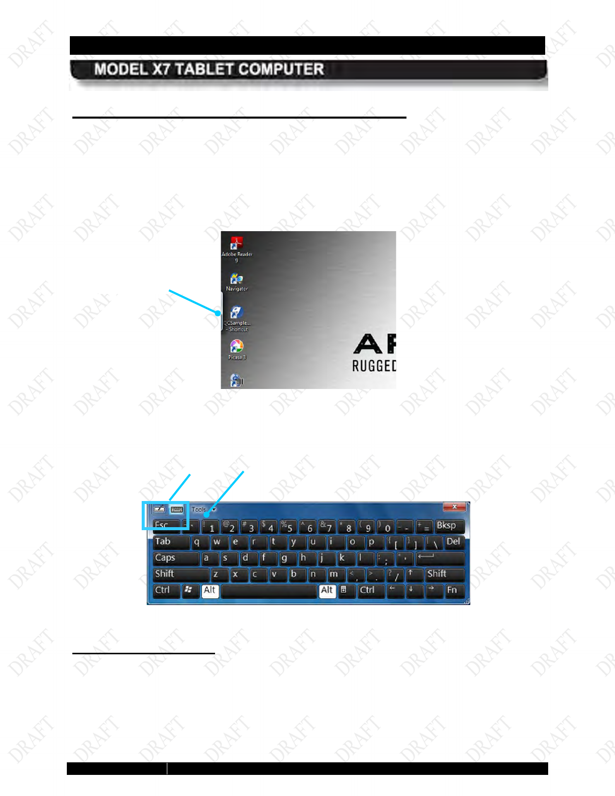
SECTION 3 GETTING STARTED PAGE 68
9711-26400-0001
EXPORT CONTROLLED – SEE PAGE 3
Rev -
The input panel is a virtual keyboard and handwriting entry tool that is located on your desktop.
Entering Data Using the Input Panel
The Input panel keyboard is normally hidden just off the left side of the display. The edge
appears in the upper left corner when you tap near it on the screen with a fingertip, stylus or the
active pen, as shown in Figure 23.
When it is visible, tap on it twice to fully open it on the desktop, as shown in Figure 24.
Figure 23. Location of the Input Panel
Figure 24. Input Panel Keyboard Opened on Desktop
The input panel has two modes: handwriting and keyboard entry. These are selectable by the
two mode icons at the upper left corner. NOTE: The panel will always open in the last mode
used.
Operating Modes
Click on the Tools menu for handwriting options and for information on how to set up and use
Input Panel.
MODE
ICONS
OPTIONS AND
HELP
HIDDEN INPUT
PANEL

SECTION 3 GETTING STARTED PAGE 69
9711-26400-0001
EXPORT CONTROLLED – SEE PAGE 3
Rev -
When you tap on an open text document such as a WordPad document, a keyboard icon will
appear on the screen. Tap on the icon to open the input panel.
Editing Documents
You can also use a side-to-side gesture to open the input panel. Select Start à Control Panel
à Hardware and Sound à Pen and Touch, then highlight Start Tablet PC Input Panel in the
Pen Actions panel and click on Settings.
Opening Input Panel with a Gesture
When the Start Input Panel Gesture Settings window opens, check the Enable start Input
Panel gesture option. Follow the instructions to test and adjust your gesture.
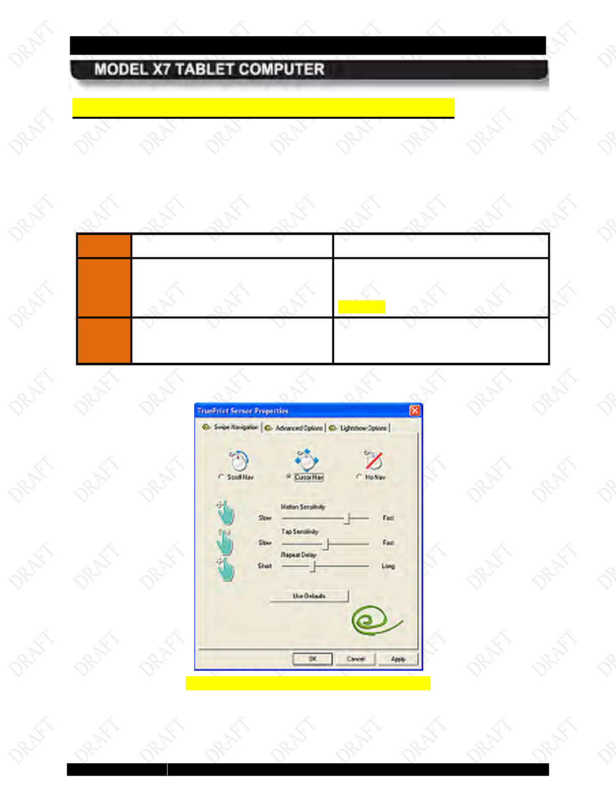
SECTION 3 GETTING STARTED PAGE 70
9711-26400-0001
EXPORT CONTROLLED – SEE PAGE 3
Rev -
The FPS mouse function is activated as soon as you start up the computer. It places an icon in
the task tray that you can used to access options and make adjustments. Follow the procedure
in
Using the FPS as a Simple Mouse Device
Table 8 to configure the FPS mouse function.
Refer to Table 9 for a list of available mouse functions using the FPS sensor.
Table 8. Configuring the FPS Mouse Function
STEP ACTION CONDITION OR INDICATION
1. Right-click on the AuthenTec icon in
the task tray. The TruePrint Sensor Properties dialog
window opens with the Swipe
Navigation tab displayed, as
shown in
Figure 25.
2.
If not already selected, click on the
Cursor Nav
option at the top of the
window.
Figure 25. FPS Sensor Properties Window
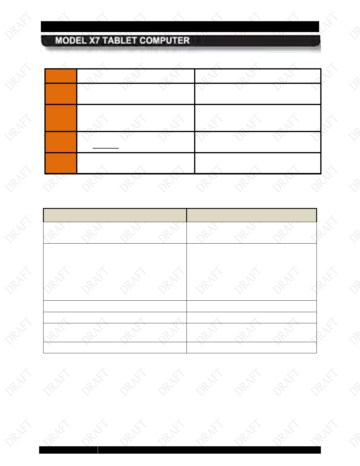
SECTION 3 GETTING STARTED PAGE 71
9711-26400-0001
EXPORT CONTROLLED – SEE PAGE 3
Rev -
STEP ACTION CONDITION OR INDICATION
3.
Move the Motion Sensitivity slider to
the right to about 80% of the scale.
4. Click on the Advanced Options tab at
the top of the window and change the
Orientation to 270°.
This aligns the mouse movement axes
with finger movement over the FPS
sensor.
5.
Click on the Lightshow Options tab
and de-select
Enable Lightshows.
6. Select Apply and then select OK.
Table 9. FPS Mouse Actions
MOUSE OBJECTIVE FPS SENSOR ACTION
Move pointer Keep thumb flat on sensor and move in
long swipes.
Select tabs or open sub-menus.
Highlight a label or option.
Fill selection boxes.
Activate buttons.
Deselect highlighted objects or release multiple
objects
Tap once.
Tap outside the object(s).
Start an application or open a folder. Tap twice.
Move an object on the desktop. - Function not available -
Open menu options. Move pointer over icon or option and press
thumb down on sensor for a few seconds.
Select multiple objects. Drag pointer to create box around objects.

SECTION 3 GETTING STARTED PAGE 72
9711-26400-0001
EXPORT CONTROLLED – SEE PAGE 3
Rev -
SECTION 3 GETTING STARTED PAGE 73
9711-26400-0001
EXPORT CONTROLLED – SEE PAGE 3
Rev -
Operating with the ARMOR X7 Vehicle Dock
Two versions of the X7 vehicle dock are available: the RF version and the Non-RF version.
The RF version has two coaxial cables attached to the docking connector to route the WWAN
radio and GPS receiver antenna connections to external antennas mounted in a vehicle.
X7 RF and Non-RF Vehicle Docks
The Non-RF version does not have the coaxial cables.
Place the X7 in the docking cradle and press down on the top latch until it locks. To remove the
X7, press on the latch locking mechanism until the latch snaps up.
Using the X7 Vehicle Dock
If you have the RF version of the dock, you will be able to connect your X7 tablet to external
WWAN and GPS antennas, which will dramatically improve reception. These antennas are
automatically switched into the tablet antenna circuits by an RF multiplexer when the tablet is
docked and switched out when it is undocked.
Either one or both antennas can be enabled using the Wireless Devices dialog in ARMORutils
(Figure 26). Follow the instructions in
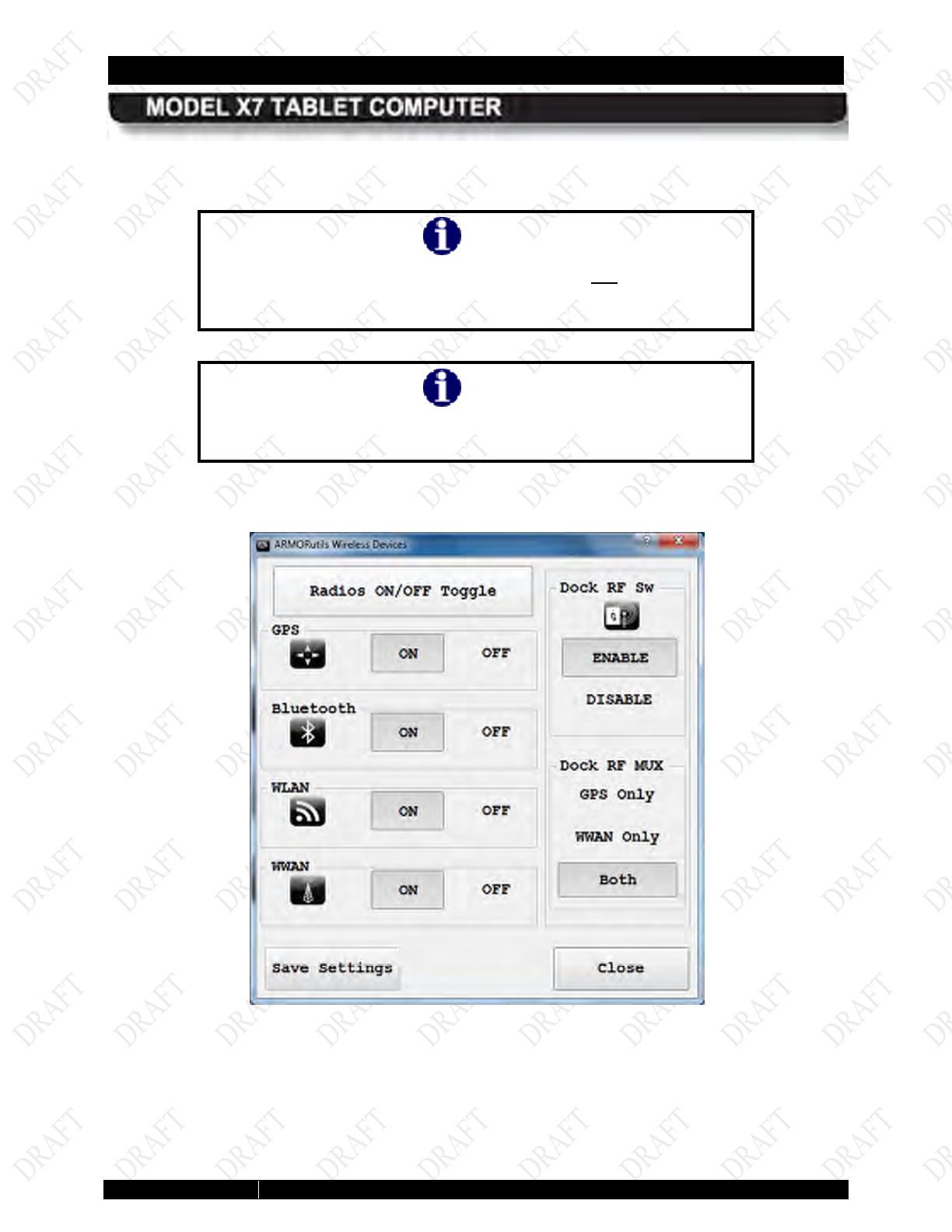
SECTION 3 GETTING STARTED PAGE 74
9711-26400-0001
EXPORT CONTROLLED – SEE PAGE 3
Rev -
NOTE
If you have an X7 RF dock installed but are not using external
antennas, you must set the Dock RF Sw to “Disable” in order to
use the tablet’s internal antennas.
NOTE
If you have an X7 Non-RF dock installed, you must set the Dock
RF Sw to “Disable” in order to use the tablet’s internal antennas.
Table 10 to configure the external antennas.
Figure 26. External Antenna Selection Options in ARMORutils
SECTION 3 GETTING STARTED PAGE 75
9711-26400-0001
EXPORT CONTROLLED – SEE PAGE 3
Rev -
NOTE
If you have an X7 RF dock installed but are not
using external
antennas, you must set the Dock RF Sw to “Disable” in order to
use the tablet’s internal antennas.
NOTE
If you have an X7 Non-RF dock installed, you must set the Dock
RF Sw to “Disable” in order to use the tablet’s internal antennas.
Table 10. Configuring the External Antennas
STEP
ACTION CONDITION OR INDICATION
1. In the Dock RF MUX
panel, select
GPS Only, WWAN Only or Both
When the tablet is docked, only the
antennas that are selected will be utilized.
2. Press the Docking RF Sw Enable or
Disable button to enable
or disable
the antenna configuration that is
selected in the Dock RF Mux panel.
SECTION 3 GETTING STARTED PAGE 76
9711-26400-0001
EXPORT CONTROLLED – SEE PAGE 3
Rev -
Using the Webcam
Image and video capture is performed using the built-in webcam and image capture software.
Your X7 is provided with a version of Picasa 3™ image editor to demonstrate the image capture
process. Other software packages with more and varied options are available.
Capturing Images and Video
Follow the procedure in Table 11 to capture and save a still image or movie using this software.
NOTE
Remove the blue protective film from the webcam lens before
using the camera.
Table 11. Capturing a Still Image or Video
STEP ACTION
1.
Double-click on the Picasa 3 icon on the desktop to open the Picasa application
window, as shown in Error! Reference source not found..
2.
Click on the “Capture photos or video…” button in the options bar. A Capture dialog
window will open displaying the current webcam image.
3.
To capture the image as a still image, click on the camera button below the image.
Each capture will appear as a thumbnail at the bottom of the window.
4.
When finished, click on the Done button to access editing and correction options or to
save or upload your images.
5.
To capture moving video, click on the Record button below the image. The capture
window will change to a viewer with options to view, save and upload your captured
video.
6.
To return to the main window, click on the Back to Library button.
7.
Refer to the Picasa Help resources for detailed instructions.
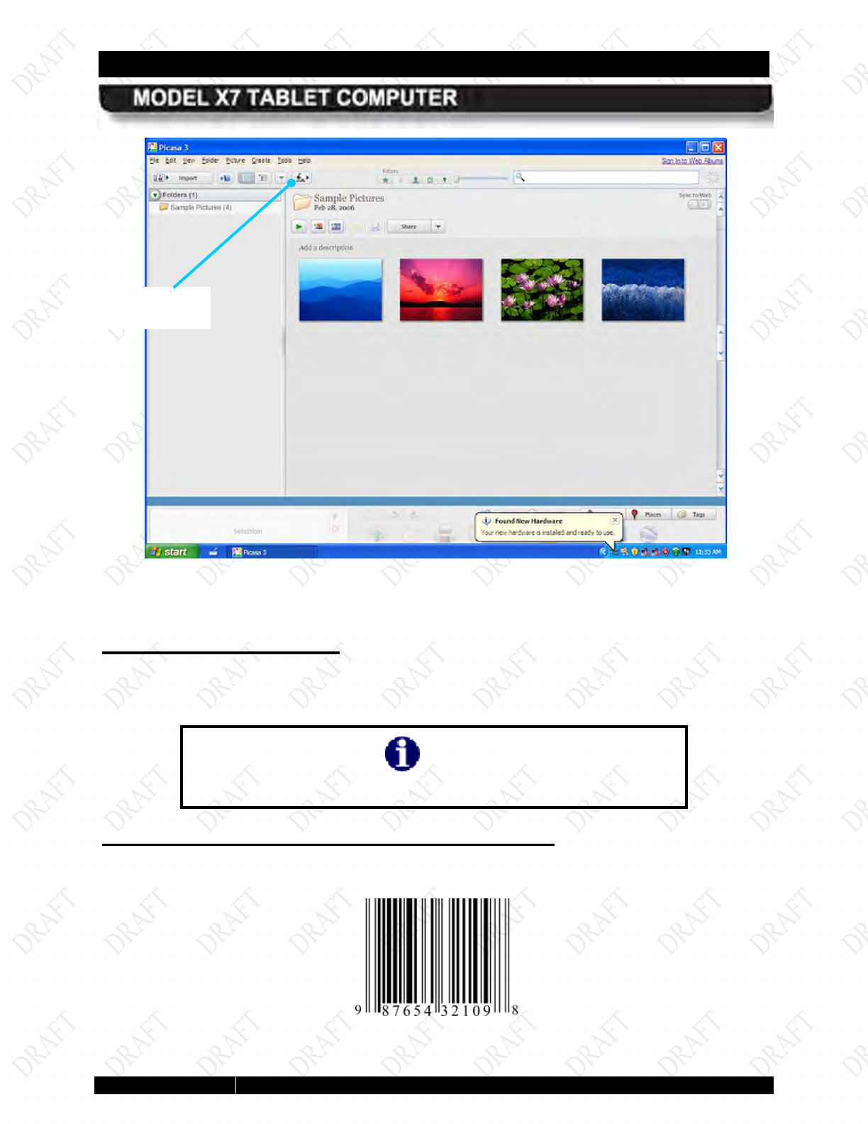
SECTION 3 GETTING STARTED PAGE 77
9711-26400-0001
EXPORT CONTROLLED – SEE PAGE 3
Rev -
Figure 27. Picasa Application Window
The built-in webcam and application software of your choice allows you to scan various types of
barcodes and incorporate them in to your documents. We have included two simple applications
to demonstrate the barcode scanning capabilities of the X7.
Scanning a Barcode
NOTE
Ensure that adequate light can reach the barcode to be scanned.
Figure 28
Linear Barcodes Such as UPC-10, EAN-13 and ISBN
shows a sample of a linear barcode. Follow the procedure in Error! Reference
source not found. to scan a linear barcode.
Figure 28. Sample Linear Barcode
CAPTURE
BUTTON
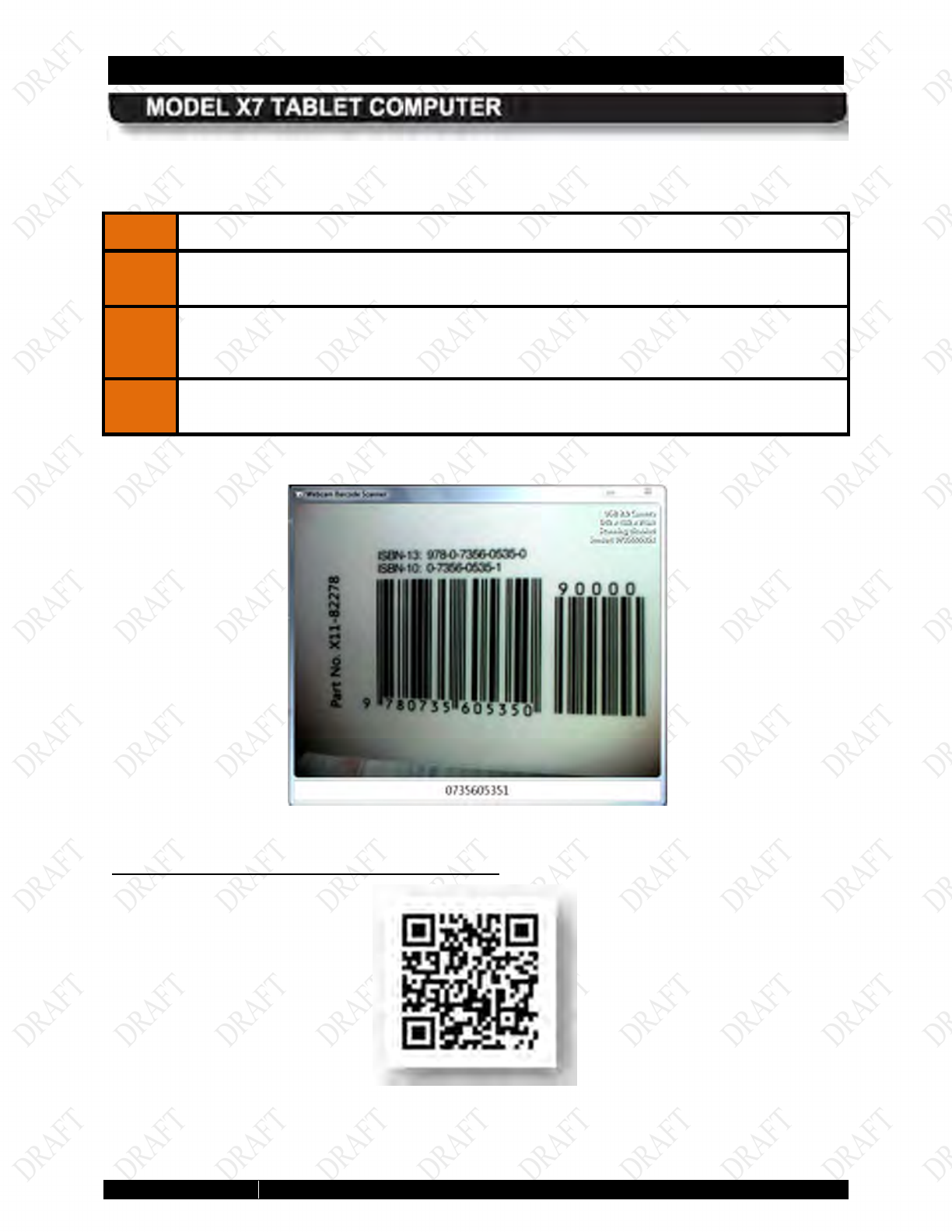
SECTION 3 GETTING STARTED PAGE 78
9711-26400-0001
EXPORT CONTROLLED – SEE PAGE 3
Rev -
Table 12. Scan UPC-10, EAN-13 and ISBN Barcodes in Windows 7
STEP ACTION
1.
Double-click on the Webcam Barcode Scanner icon on the desktop to open the
application window, as shown in Figure 29.
2.
Hold the barcode to be scanned 2-3” from the camera and hold it steady. A tone will
announce successful barcode capture, and the barcode number will appear at the
bottom of the window. The captured barcode is stored in the Windows clipboard.
3.
To use a barcode in an application, open the application, place the pointer in a field
and paste.
Figure 29. Webcam Barcode Scanner® Barcode Scanner Application Window
A sample 2D barcode is shown in
2D Barcodes in Datamatrix or QR format
Figure 30. Follow the procedure in Error! Reference source not found. to scan a 2D barcode.
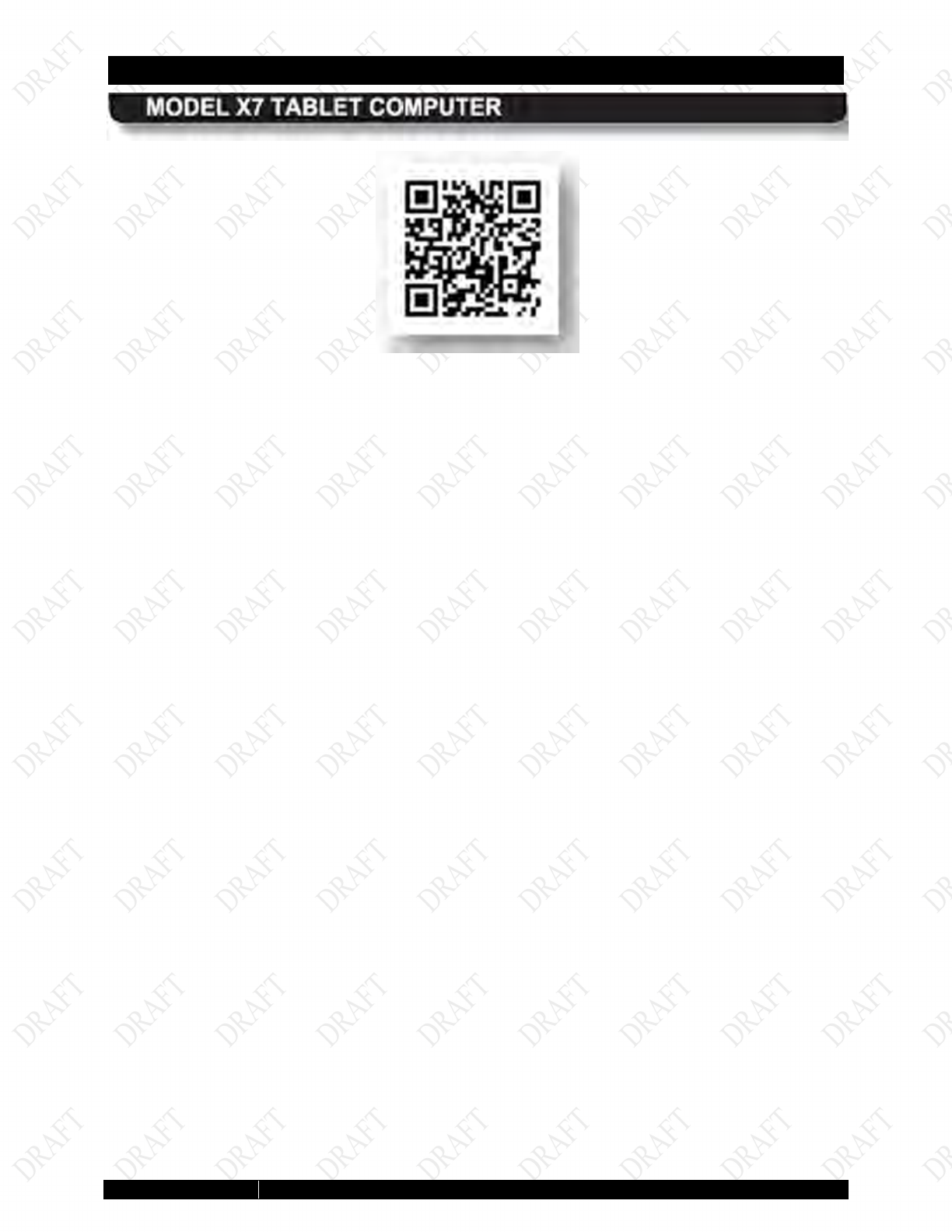
SECTION 3 GETTING STARTED PAGE 79
9711-26400-0001
EXPORT CONTROLLED – SEE PAGE 3
Rev -
Figure 30. Sample 2D Barcode
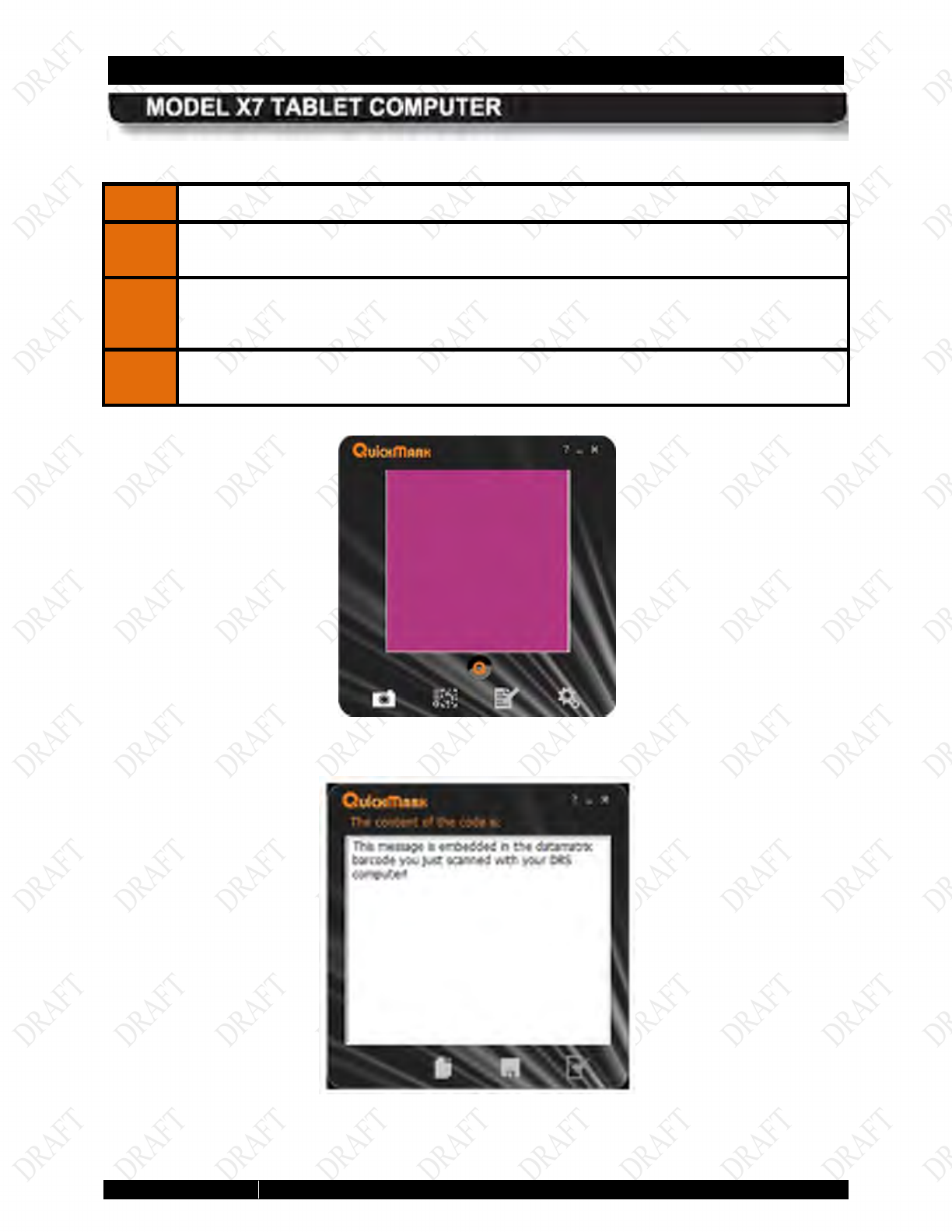
SECTION 3 GETTING STARTED PAGE 80
9711-26400-0001
EXPORT CONTROLLED – SEE PAGE 3
Rev -
Table 13. Scan Datamatrix and QR Format Barcodes in Windows 7
STEP ACTION
1.
Double-click on the QuickMark icon on the desktop to open the QuickMark®
application window, as shown in Figure 31.
2.
Hold the barcode to be scanned 2-3” from the camera; an audible signal will sound
upon capture and the barcode information will be displayed in the application window,
as shown in Figure 32.
3.
To return to the camera mode, click door icon at the lower right corner of the window.
Figure 31. QuickMark® Barcode Scanner Application Window
Figure 32. A Captured 2D Barcode
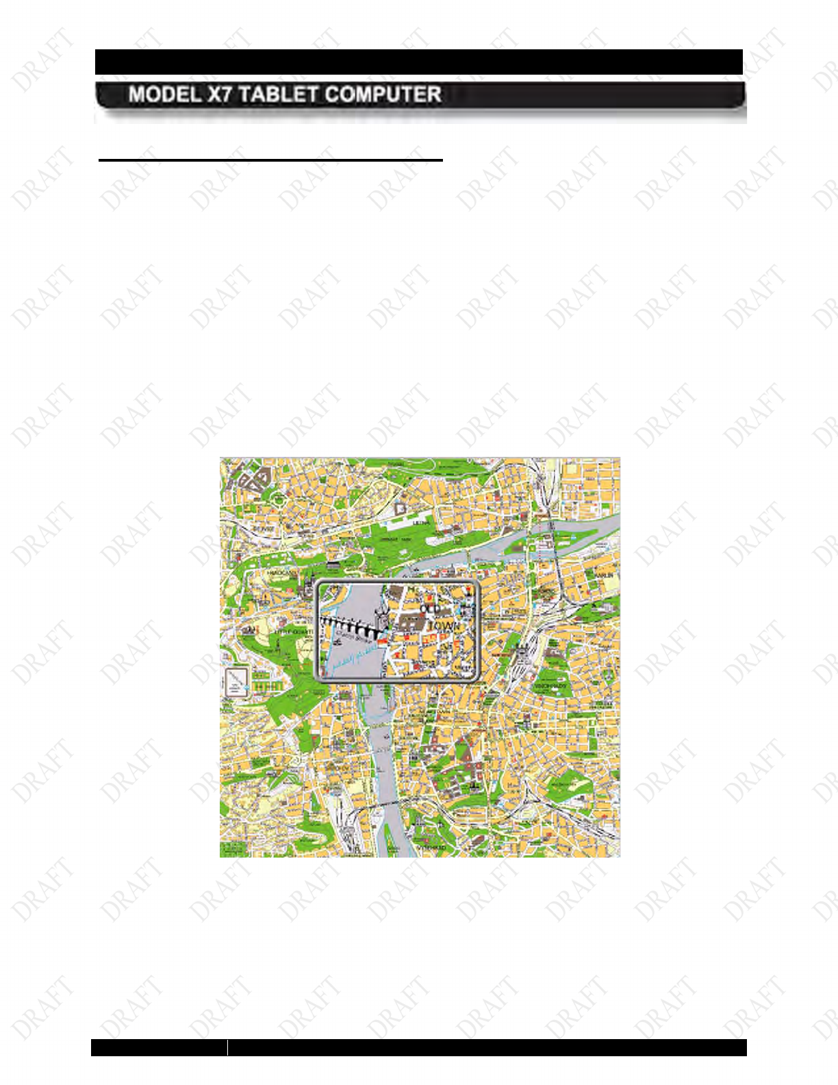
SECTION 3 GETTING STARTED PAGE 81
9711-26400-0001
EXPORT CONTROLLED – SEE PAGE 3
Rev -
Some text and images on a small screen can be difficult to see clearly. Your X7 has a handy
application that will magnify a portion of the screen and help you see more effectively. The
program is called Virtual Magnifying Glass™.
Using the Screen Magnifier
• To start the application, click on the Virtual Magnifying Glass icon on the desktop or
select Start > Programs > Virtual Magnifying Glass.
• Use the Scroll wheel to increase or decrease magnification. The application will return to
the last magnification when restarted.
• Left click to close the magnifier.
• To access the configuration menu, right-click on the icon in the task bar.
• A magnified example is shown in Figure 33.
Figure 33. Virtual Magnifying Glass at Work

SECTION 3 GETTING STARTED PAGE 82
9711-26400-0001
EXPORT CONTROLLED – SEE PAGE 3
Rev -
There are certain precautions you should take to ensure that your ARMOR X7 computer
continues to provide you with reliable service:
Tips for Proper Use and Care Of Your X7
• Do not subject the computer to heat by placing it on the dashboard of a vehicle with the
display facing the sun.
• Do not store the computer in temperatures below -40°C or above 70°C.
• Do not pile tools or heavy objects on top of the computer.
• Avoid severe impacts, especially to the display.
• Do not try to take the computer apart. Disassembly of the unit by unauthorized personnel
may void your warranty.
• Keep your screen clean and calibrated.

SECTION 3 GETTING STARTED PAGE 83
9711-26400-0001
EXPORT CONTROLLED – SEE PAGE 3
Rev -
This Page Intentionally Left Blank
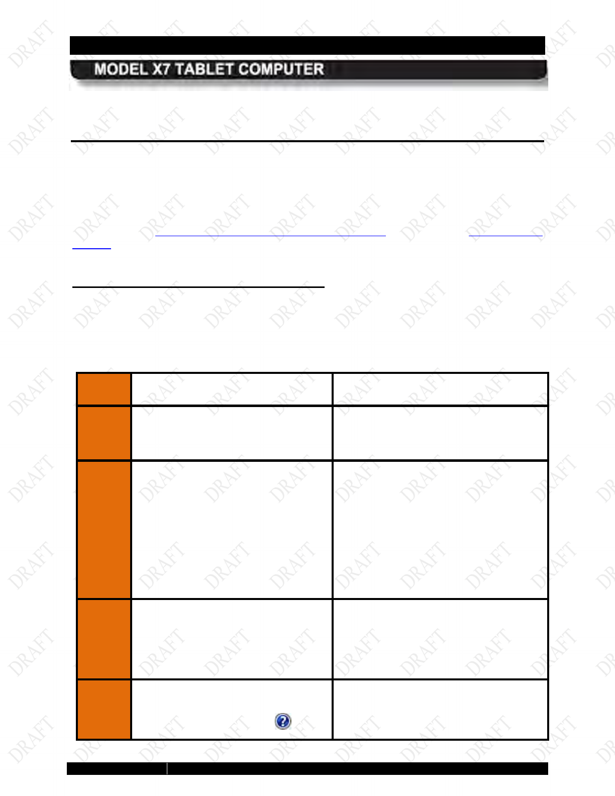
SECTION 4 NETWORKING PAGE 84
9711-26400-0001
EXPORT CONTROLLED – SEE PAGE 3
Rev -
4. NETWORKING
Your ARMOR X7 comes configured with two wireless network capabilities: Wi-Fi™ (wireless
fidelity) and Bluetooth(r). The Wi-Fi network is primarily used for higher bandwidth connections
such as Internet or a company LAN. The Bluetooth network is used for connecting wireless
devices such as a wireless printer or scanner to your computer.
The X7 can also accommodate an optional WWAN radio and/or a GPS receiver. These radios
are described in Optional Add-ons and Accessories for Your X7. Please contact DRS Technical
Support for information about installing these options.
Your WI-FI (WLAN) radio is already configured and operating. Refer to
Managing your WI-FI Radio
Table 14 for instructions
on how to establish and manage your WLAN connections.
Table 14. View and Manage Network Connections
STEP ACTION CONDITION OR INDICATION
1. Select Start
à
Control Panel
à
Network and Internet
à
Network
and Sharing Center.
The window shown in Figure 34 opens.
2. Click on the “Connect to a network”
link to open th
e window shown in
Figure 35. Click outside this window to
close it.
The label “Connected” will appear beside
each network you are currently
connected to. Any other available
networks are also listed.
The green signal bars indicate the
relative strength of the wireless signal. A
yellow shield indicates those sites that do
not have security enabled. Use caution
when connecting to these sites.
3. To connect to a network, click on the
network name and select Connect. To
disconnect from an active network,
click on the name and select
Disconnect.
4.
For more detailed information on the
options and settings for these
windows, click on the Help icon
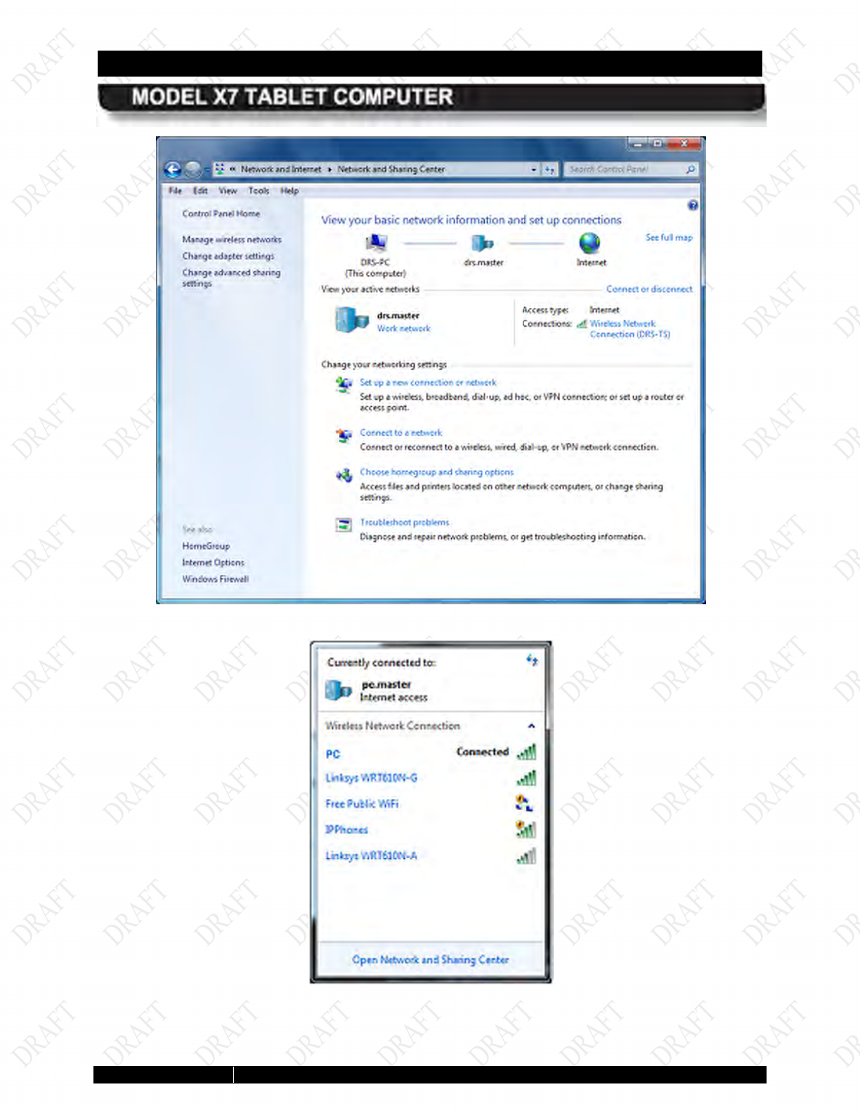
SECTION 4 NETWORKING PAGE 85
9711-26400-0001
EXPORT CONTROLLED – SEE PAGE 3
Rev -
Figure 34. Windows Network and Sharing Center
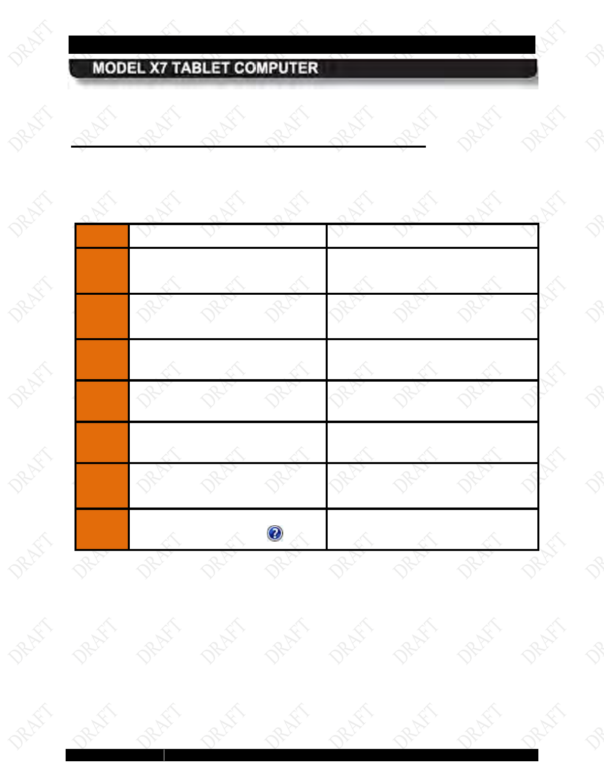
SECTION 4 NETWORKING PAGE 86
9711-26400-0001
EXPORT CONTROLLED – SEE PAGE 3
Rev -
Figure 35. Currently Connected and Available Wi-Fi Networks
Your X7 comes equipped with Bluetooth® networking. To utilize this feature, you must
“associate” this computer with your Bluetooth devices. To see what Bluetooth devices are
available and to add or remove devices, follow the procedure in
Managing Your Bluetooth Connections
Table 15.
Table 15. View and Manage Bluetooth Devices
STEP
ACTION CONDITION OR INDICATION
1. Select Start
à
Control Panel
à
Hardware and Sound
à
Devices
and Printers.
A window opens (Figure 36) showing any
peripherals connected or available
(including cabled devices).
2. Right-
click on the icon for your
computer and select Bluetooth
settings from the menu.
The Bluetooth Settings window opens, as
shown in Figure 37.
3. Check the “
Allow Bluetooth devices
to find this computer” option.
4. Check the “
Allow Bluetooth devices
to connect to this computer” option.
5. To add a device, click on the “
Add a
device” option in the toolbar.
6.
To remove a device, click on the
“Remove a device” option in the
toolbar.
7. For additional information about these
windows, click on the Help icon.
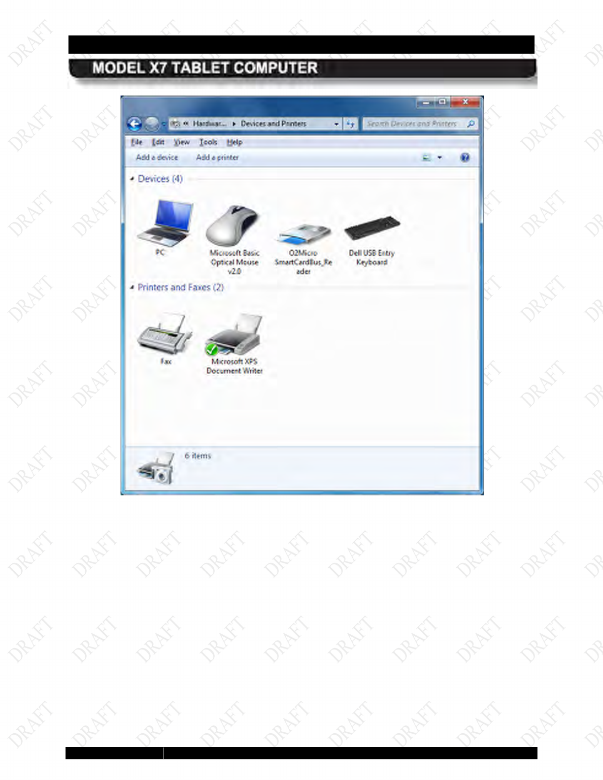
SECTION 4 NETWORKING PAGE 87
9711-26400-0001
EXPORT CONTROLLED – SEE PAGE 3
Rev -
Figure 36. Devices and Printers Window
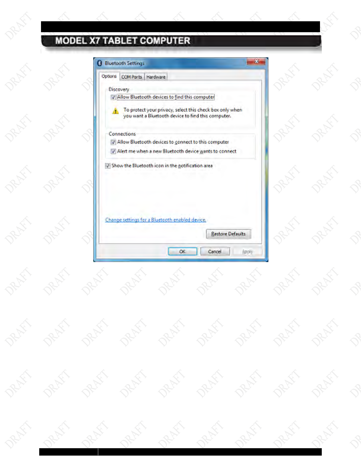
SECTION 4 NETWORKING PAGE 88
9711-26400-0001
EXPORT CONTROLLED – SEE PAGE 3
Rev -
Figure 37. Bluetooth Settings Window
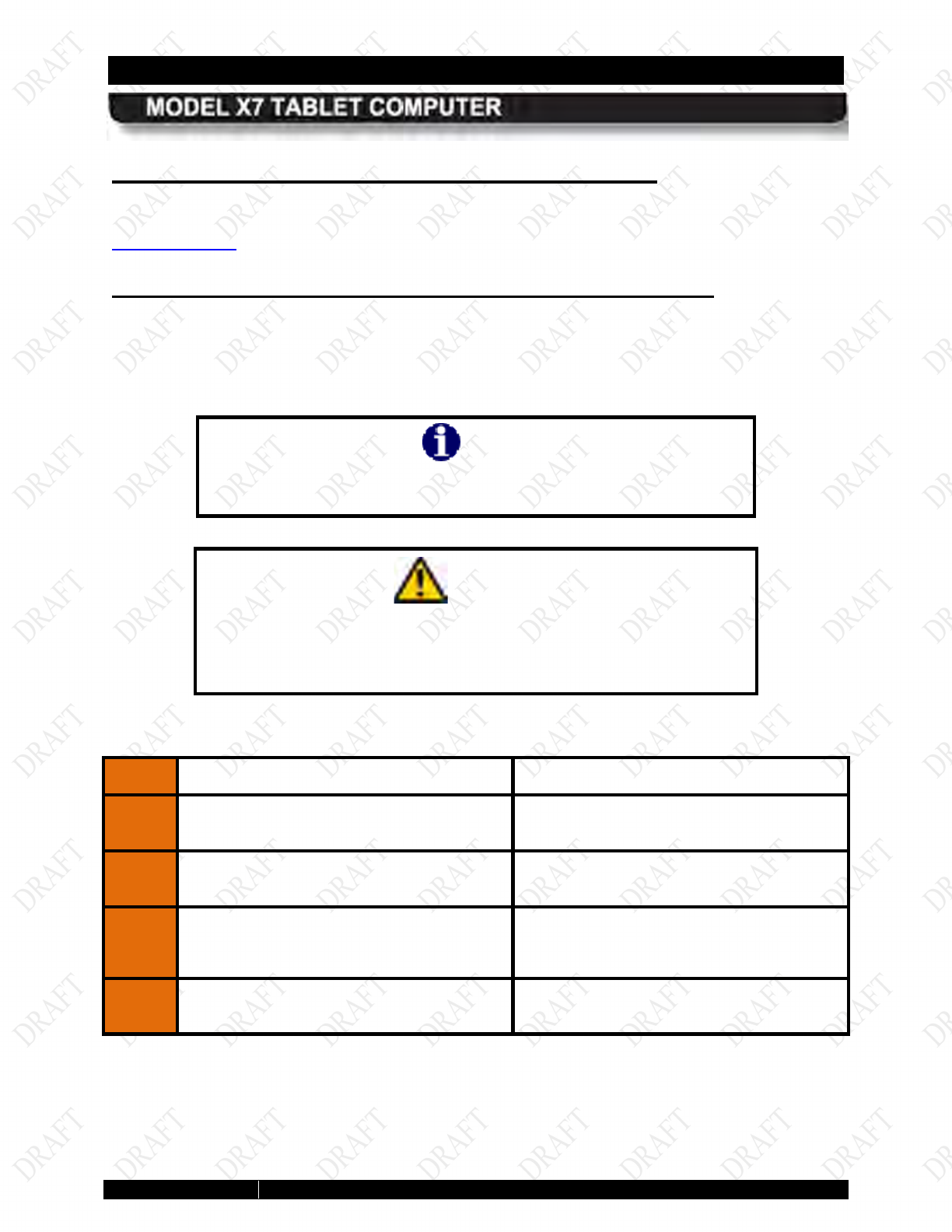
SECTION 4 NETWORKING PAGE 89
9711-26400-0001
EXPORT CONTROLLED – SEE PAGE 3
Rev -
If your WWAN network does not require a SIM, skip to
If you have the Optional WWAN Radio
Connecting to a . WWAN
For certain networks like GSM, you must install a valid SIM before you can activate and use
your WWAN radio. The SIM is obtained from your WWAN service provider and is installed in a
socket located inside the rear compartment, as shown in
Installing the Subscriber Identity Module (S IM)
Figure 38.
Follow the procedure in Table 16 to access the rear compartment and install the SIM.
NOTE
This procedure should only be performed by a qualified
technician in a controlled environment.
CAUTION!
Circuit boards containing electrostatic discharge (ESD) sensitive
devices are exposed in this compartment. Static-free handling is
required to prevent possible damage to the components.
Table 16. Installing a SIM
STEP ACTION CONDITION OR INDICATION
1.
Power down the computer and disconnect
any external power.
2.
Remove the batteries.
3.
Place the computer face down on a clean
surface and remove the 14 Philips screws
securing the cooling register (rear cover).
4.
Carefully pry up the register at the slot
provided (Figure 38) and remove.
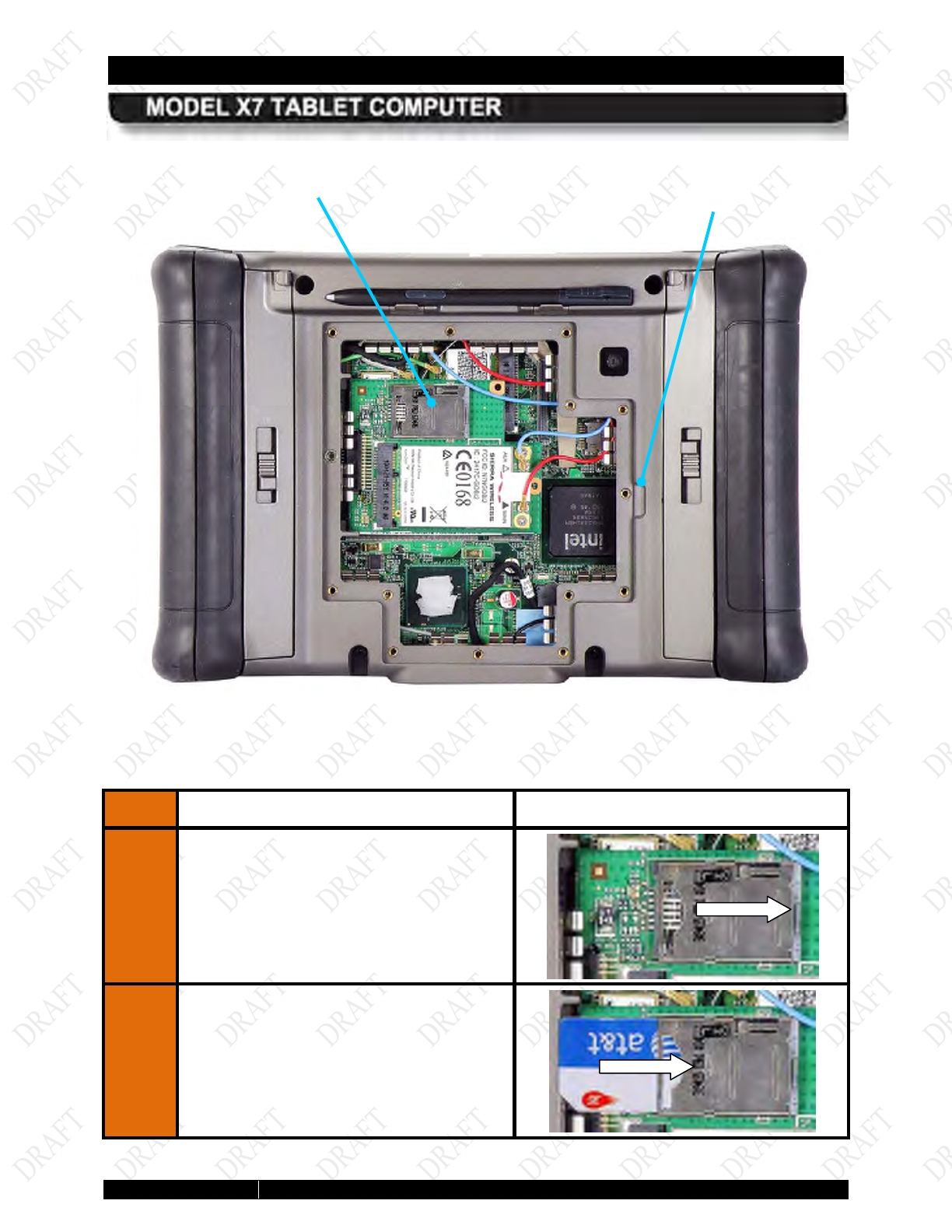
SECTION 4 NETWORKING PAGE 90
9711-26400-0001
EXPORT CONTROLLED – SEE PAGE 3
Rev -
Figure 38. X7 Rear Compartment
STEP ACTION CONDITION OR INDICATION
5.
Place a fingertip in the notch
on the left
side of the SIM socket cover and slide the
cover to the right until you feel an indent,
then lift up.
6.
Insert the SIM with the corner notch at the
lower left.
SIM
SOCKET
COVER
REMOVAL
SLOT
SECTION 4 NETWORKING PAGE 91
9711-26400-0001
EXPORT CONTROLLED – SEE PAGE 3
Rev -
7.
Gently press the cover down and slide to
the left to lock in place.
8.
Reinstall the cooling register and secure
with the 14 Philips screws. Be careful not
to over-tighten the screws.
Once your card is installed (if required), you are ready to activate your network connection.
Follow the procedure in
Connecting to a WWAN
Table 17 to connect to a WWAN.
Table 17. Connecting to a WWAN
STEP ACTION CONDITION OR INDICATION
1. Click on the OneClick Internet icon
on the desktop or Select Start
à
All
Programs
à
OneClick Internet
The Sierra® OneClick™ Internet
Connection Manager window opens, as
shown in Figure 39.
2.
Select Settings and then click on the
General tab. The Settings window opens, as shown in
Figure 40.
3. Select the Gobi NDIS Auto Connect
option.
This option automatically controls
launching the connection application,
connecting to the network, reconnecting if
you lose contact, and roaming.
4.
If you wish to be alerted when
roaming, select the Roaming Alert
option.
The connection is made and a list of
connection statistics is displayed in the
right panel.
NDIS Notes:
• NDIS turns the WWAN radio on even before the OS starts. This is not always a
desirable state, so choose NDIS only if needed.
• Because NDIS enables the Gobi WWAN hardware
• Auto Launch is not recommended for use with NDIS – it will launch the Connection
Manager application upon reboot, restarting the connection.
to connect, reconnect and roam
automatically, those selections are ignored if chosen in conjunction with NDIS.
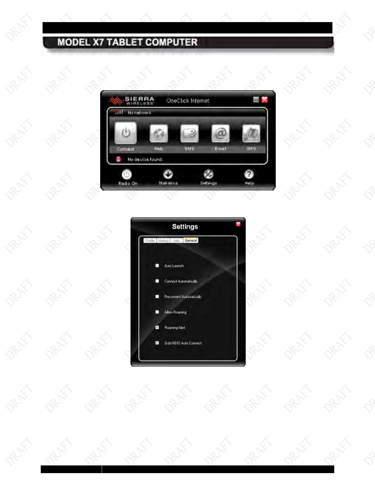
SECTION 4 NETWORKING PAGE 92
9711-26400-0001
EXPORT CONTROLLED – SEE PAGE 3
Rev -
Click on the Help button on the OneClick Internet connection manager window (Figure 39) for
detailed information on using the Sierra application.
Figure 39. Sierra OneClick Connection Manager Window
Figure 40. Settings Window
SECTION 4 NETWORKING PAGE 93
9711-26400-0001
EXPORT CONTROLLED – SEE PAGE 3
Rev -
The u-center GPS application is bundled with the X7 software suite but is only functional if you
have the optional GPS receiver installed.
If you have the Optional GPS Receiver
Before you can use your u-center software, you must manually obtain and enter the
communications port that was assigned to the u-center by Windows. To do this, follow the
procedure in Table 18.
Table 18. Configuring the u-Center com port
Step Action Comment
1. From the Windows desktop, select the
Start button and select
Control Panel
à
Hardware and Sound
à
Devices
and Printers
à
Device Manager
The Device Manager dialog window will
open.
2. Open the Ports (COM & LPT) option
and record the COM port currently
assigned to u-
blox 5 GPS and
GALILEO Receiver.
3. Close Control Panel and open the u-
center application by double-clicking on
the u-center desktop icon or selecting
the u-center option from the All
Programs list.
The u-
center application window opens
as shown in Figure 41.
4. Select the Receiver
menu in the
application tool bar and click on the
Port option.
5. Choose the COM port that you recorded
from Control Panel.
Your GPS receiver will automatically
begin searching for satellites.
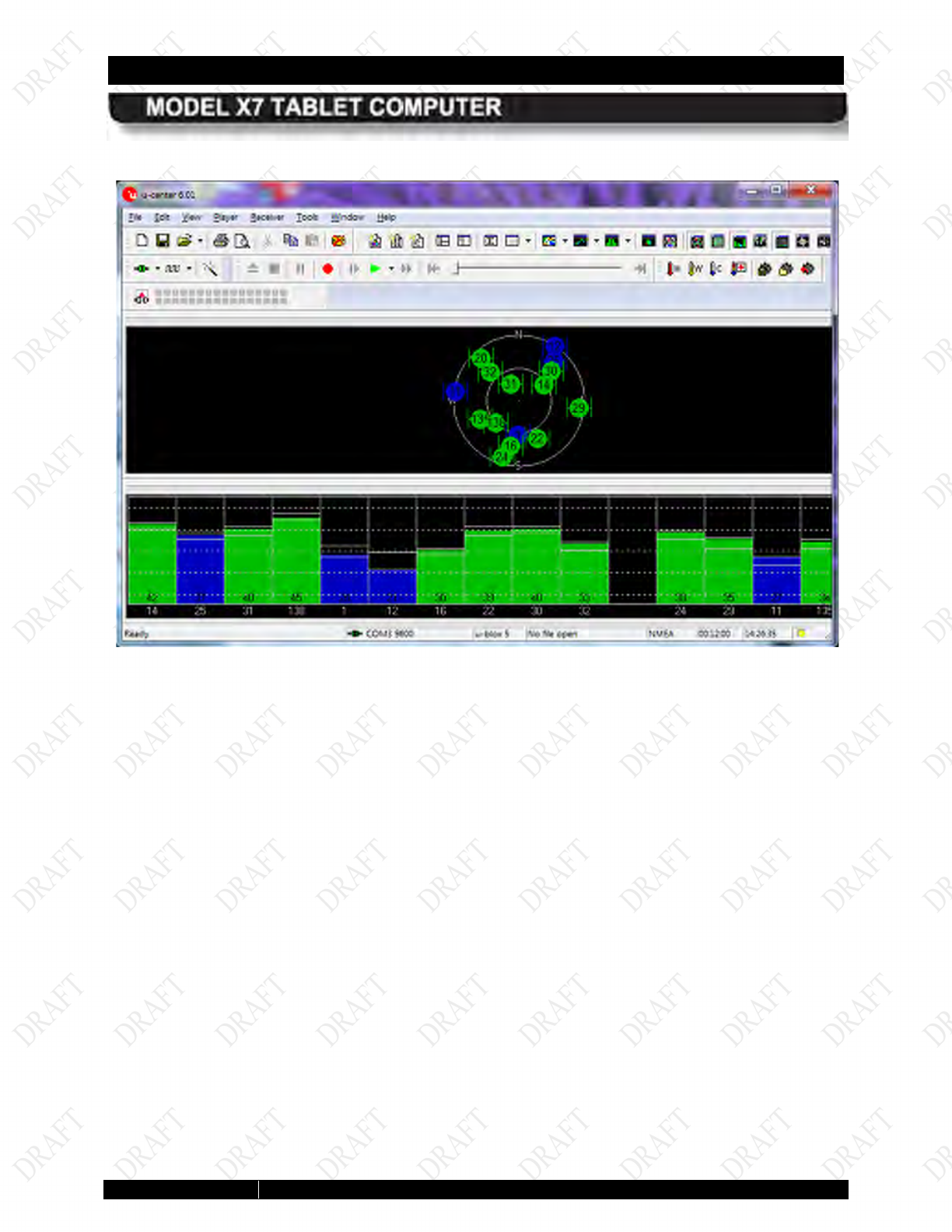
SECTION 4 NETWORKING PAGE 94
9711-26400-0001
EXPORT CONTROLLED – SEE PAGE 3
Rev -
Figure 41. U-Center GPS Application Window
The diagram in the center shows the approximate positions of satellites relative to your location
that are within range of the receiver. The graph at the bottom of the page shows the signal
strength of each satellite. A green bar indicates acceptable signal strength; a blue bar indicates
marginal reception. You must have at least four satellites with acceptable signal strength to
generate reliable position data.
Click on the Help tab at the top of the window for guidance on accessing, interpreting and using
the GPS information.
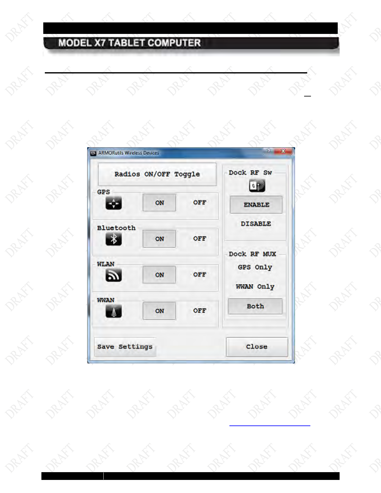
SECTION 4 NETWORKING PAGE 95
9711-26400-0001
EXPORT CONTROLLED – SEE PAGE 3
Rev -
You may want to turn off one or more of your radios to save power, to avoid interfering with
other radio systems, or just to ensure your privacy. Or you may want to turn off
Enabling and Disabling Your Wireless Radios
all
Click on the ARMORutils icon on the desktop and select the Wireless Setup option. This will
open the Wireless Devices page, as shown in
of your
wireless radios at one time but keep working on your computer, as when travelling on an
aircraft.
Figure 42.
Figure 42. ARMORutils Wireless Devices Page
Click on the ON or Off button to enable or disable each individual radio that is installed, then
click the Save Settings button to save your configuration. Click on the Radios ON/OFF Toggle
button to turn off all enabled radios at one time. Click it again to turn them all back on.
For use of the Dock RF Sw and Dock RF MUX options, see Using the X7 Vehicle Dock.

SECTION 4 NETWORKING PAGE 96
9711-26400-0001
EXPORT CONTROLLED – SEE PAGE 3
Rev -
Wireless signal quality is affected by several conditions:
Wireless Signal Quality
• Distance from a Wi-Fi access point.
• Access rights (set up through an administrator).
• Your security settings.
• Orientation of the wireless antennas.
If you are having difficulty connecting to your network, try the following steps:
1. Open the Wireless Devices page in ARMORutils and verify that the radio is enabled.
2. If your tablet is not locked in a vehicle mount, try turning the unit in various directions to
improve signal quality.
3. Try to get closer to the access point.
4. Move away from obstacles such as trees and metal objects which may be between you
and the Access Point.
5. Verify that the Wi-Fi access point is operating.
If none of these actions solves the problem, contact your Network Administrator for
assistance.
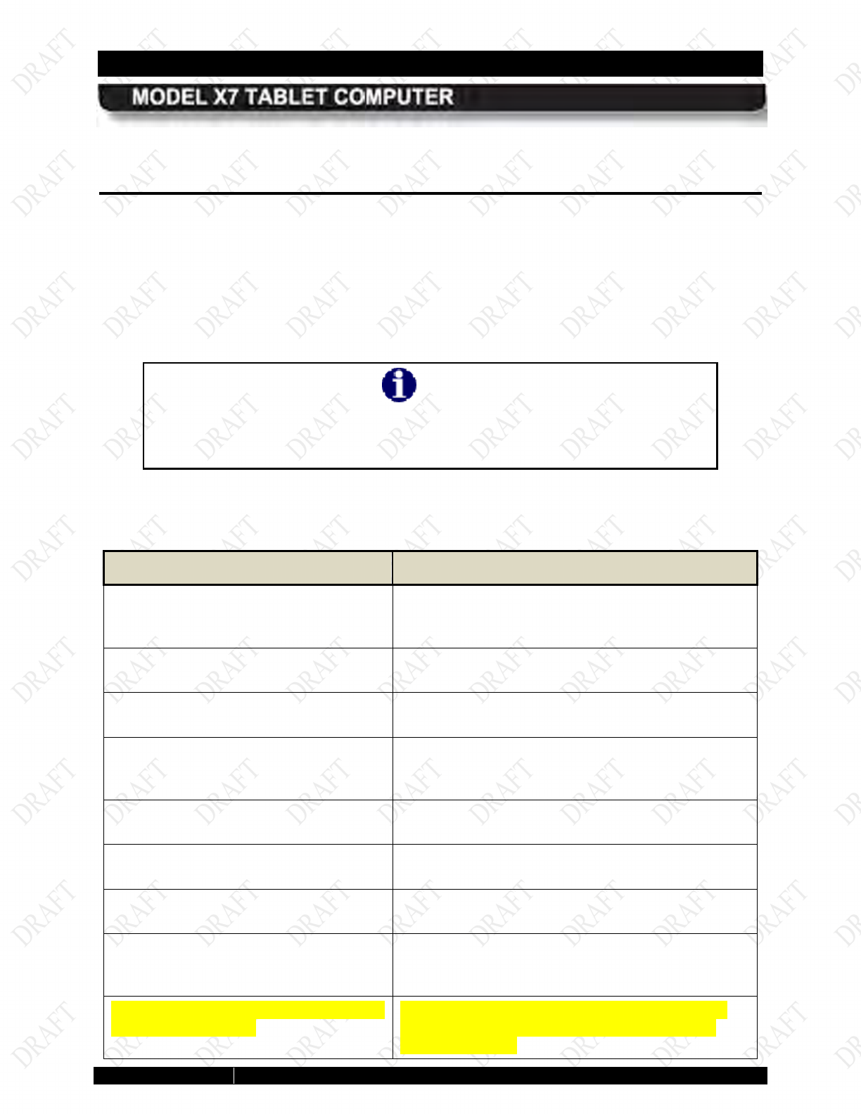
SECTION 5 YOUR ARMOR X7 SOFTWARE PAGE 97
9711-26400-0001
EXPORT CONTROLLED – SEE PAGE 3
Rev -
5. YOUR ARMOR X7 SOFTWARE
Your ARMOR X7 comes with a variety of software applications. Many of these are standard
with the Windows 7 operating system, some are provided by DRS to improve your configuration
and control of the computer and some may be custom software provided for add-ons and
special requirements.
Table 19 lists the software bundled with your X7 purchase. The paragraphs following provide
you with an overview of these software applications.
NOTE
A detailed description of each setting and option (with the exception of
programs created by DRS) is beyond the scope of this manual. Please refer
to the help resources provided with each software application.
Table 19. Software Included with your X7 Purchase
APPLICATION PURPOSE
Microsoft® Windows 7 Professional™
or Windows Ultimate™ Operating
System
Controls the processing, display, wireless
communications and media functions of the
computer.
DRS ARMORutils® (ARMOR Utilities) Provides settings and information used to
configure and maintain your X7.
Windows Pen and Touch Utility Provides settings for interacting with the touch and
pen screens.
Windows Tablet PC Settings Utility Provides settings for calibrating the pen and touch
screens and for customizing the action of the pen
and fingertip.
Windows Pen Tablet Properties Utility Provides settings and extended capabilities for the
active pen, plus access to calibration routines.
Sierra Wireless® One
Click Internet
Connection Manager™ Provides configuration and connection
management of the optional Gobi® WWAN radio.
UBlox® u-center™ GPS application Controls the GPS receiver and acts as the data
interface for Windows applications.
Realtek® HD Audio Manager™
application Provides sound settings and adjustments for the
internal speaker and for optional external
headphones.
TruePrint®
Fingerprint Sensor
Navigator application Allows the fingerprint sensor to be used to steer
the pointer on the desktop and perform simple
mouse functions.
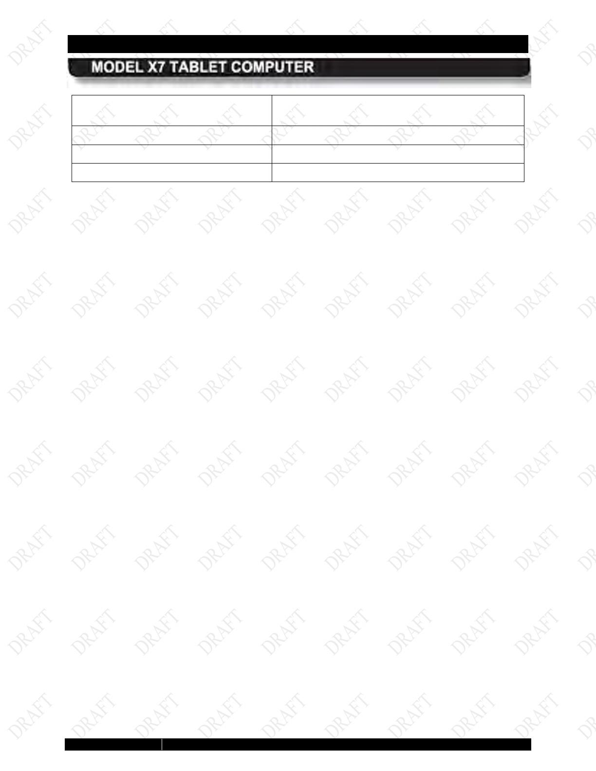
SECTION 5 YOUR ARMOR X7 SOFTWARE PAGE 98
9711-26400-0001
EXPORT CONTROLLED – SEE PAGE 3
Rev -
Picasa 3® Image Capture Application Works with the webcam to capture still images and
movies.
WebcamBarcodeScanner™ Allows the webcam to capture linear barcodes.
QuickMark™ barcode scanner Allows the webcam to capture 2D barcodes.
Virtual Magnifying Glass™ Provides a handy screen magnifier.
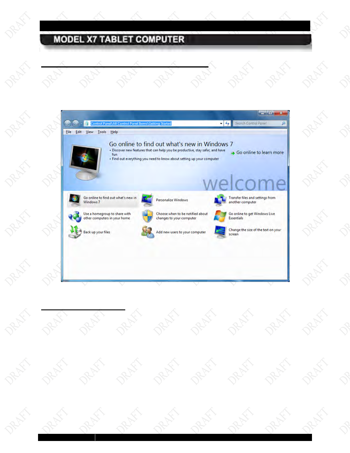
SECTION 5 YOUR ARMOR X7 SOFTWARE PAGE 99
9711-26400-0001
EXPORT CONTROLLED – SEE PAGE 3
Rev -
Click on Start à Getting Started to open the Windows welcome page (
Getting Started with Windows 7
Figure 43) and access
a number of helpful links and resources. NOTE: Screen content and layout may vary depending
on your version of Windows 7 and any added service packs or updates.
Figure 43. Windows 7 Welcome Page
For information on using Microsoft Window’s features, options, applications and utilities, refer to
the Microsoft help files and documentation on the X7 computer by clicking on the Start button
and selecting Help and Support.
Help for Windows
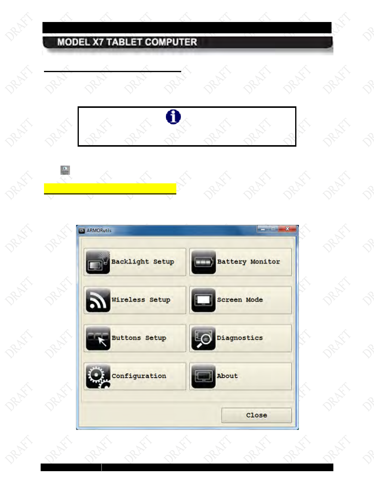
SECTION 5 YOUR ARMOR X7 SOFTWARE PAGE 100
9711-26400-0001
EXPORT CONTROLLED – SEE PAGE 3
Rev -
The ARMORutils application is provided to help you configure and manage your X7 computer. It
contains settings and information about screen setup, wireless configuration, battery status and
much more.
ARMORutils Application
NOTE
The screen images in this section are used for reference only and
may not reflect the actual configuration of your X7.
To open the ARMORutils main dialog window (Figure 44), double-click on the ARMORutils
icon on the desktop or select Start à All Programs à ARMORutils.
The ARMORutils main window is shown in
ARMORutils Main Window
Figure 44. Seven buttons provide access to setup
and configuration or information dialog windows. Click on a button to access one of these dialog
windows.
Figure 44. ARMORutils Main Window
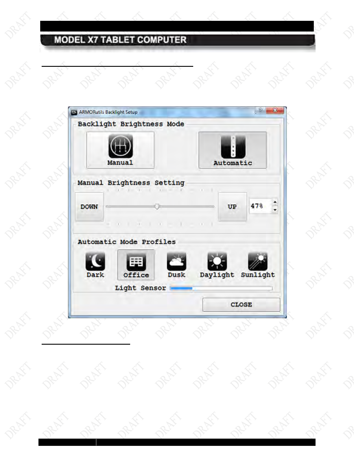
SECTION 5 YOUR ARMOR X7 SOFTWARE PAGE 101
9711-26400-0001
EXPORT CONTROLLED – SEE PAGE 3
Rev -
The Backlight Setup dialog window allows you to adjust the screen brightness manually or
automatically and to select from a series of preset profiles to automatically restrict the
brightness range under specific lighting conditions.
Backlight Setup Dialog Window
Figure 45. ARMORutils Backlight Setup Page
The Manual button is initially activated by default. To manually adjust screen brightness, click
repeatedly on the UP or DOWN buttons in the Manual Brightness Setting panel or drag the
slider. The current brightness level is displayed as a percentage in the window to the right of the
UP button. You can also adjust the brightness by clicking on the up and down arrows next to the
percentage readout.
Manual Brightness Mode
The manual controls change the brightness from 0% to 100% of the total available adjustment
range for Manual mode. At the 0% point, the brightness low but the screen is not totally dark.
SECTION 5 YOUR ARMOR X7 SOFTWARE PAGE 102
9711-26400-0001
EXPORT CONTROLLED – SEE PAGE 3
Rev -
Click on the Automatic button to activate the automatic brightness control mode. Automatic
brightness adjustment is controlled by the ambient light sensor (ALS) located on the indicator
panel on the front of your X7 tablet. The ALS monitors the surrounding (ambient) light level and
automatically adjusts the backlight level to maintain the same relative screen brightness. For
example, if you are working in an office near a window and someone opens the blinds, the
surrounding light will suddenly increase. The ALS will measure the increase in light level and
automatically increase your screen and indicator brightness to compensate.
Automatic Brightness Mode
Unlike Manual mode, where you can vary the brightness across a much larger adjustment
range, in Automatic mode, the total range of brightness adjustment is smaller and is determined
by the selected Automatic Mode Profile.
When you first start ARMORutils, the system defaults to the Office profile. Once you select a
different profile, the tablet will continue to use that profile until you select another.
If you are in Manual mode and you click on one of the automatic profile settings, the brightness
mode will switch to Automatic mode. Conversely, if you are in Automatic mode and click on the
Manual mode UP or DOWN button, or one of the up/down arrows, the brightness mode will
switch to Manual mode.
Switching Between Brightness Modes
Everyone’s eyes react differently to changes in light levels and there may be times when the full
range of automatic brightness adjustment is uncomfortable for you.
Automatic Mode Profiles
You can tailor the automatic brightness adjustment by selecting one of the 5 pre-configured
brightness profiles: Dark, Office, Dusk, Daylight, and Sunlight. These profiles control the range
of brightness levels to values based on typical surroundings or times of day.
For example, if you typically work in an office environment but the automatic brightness doesn’t
make the display bright enough for you, you can select the Dusk, Daylight or Sunlight profile to
increase the brightness range proportionally. Similarly, if the normal brightness control results in
displays that are too bright, you can select the Office or Dark profile to reduce the brightness
range.
The Light Sensor bar provides a visual indication that the ALS circuit is functioning correctly.
Screen brightness changes in response to the changing ambient light level occur gradually to
allow your eyes to adjust and may not be readily apparent, but the Light Sensor bar gives an
immediate indication that the ALS is controlling the screen brightness. The Light Sensor bar will
continue to operate even when the backlight mode is set to Manual.
Light Sensor Bar
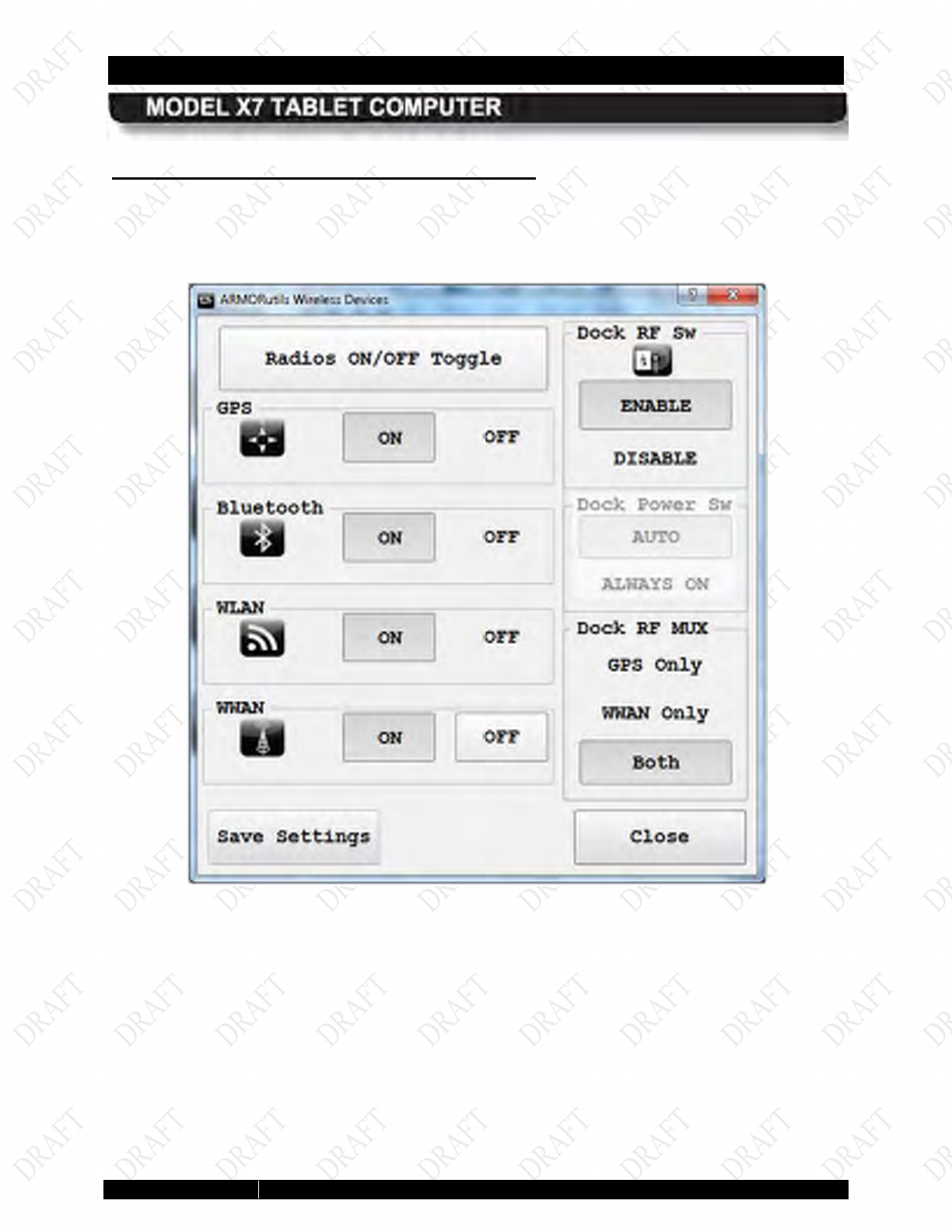
SECTION 5 YOUR ARMOR X7 SOFTWARE PAGE 103
9711-26400-0001
EXPORT CONTROLLED – SEE PAGE 3
Rev -
The Wireless Devices page allows you to enable or disable all of the installed wireless devices
in your ARMOR X7. It also provides controls for external antennas connected through an X7
vehicle dock.
Wireless Devices Dialog Window
Figure 46. ARMORutils Wireless Devices Page
SECTION 5 YOUR ARMOR X7 SOFTWARE PAGE 104
9711-26400-0001
EXPORT CONTROLLED – SEE PAGE 3
Rev -
There is an ON and Off button for each radio that can be installed in the X7. When you first start
your ARMOR X7, all installed radios are ON or enabled (default condition). Each radio can then
be disabled by pressing its OFF button and re-enabled by pressing its ON button.
Radio ON/OFF Buttons
There are RF docking connectors on the X7 dock for an external wireless antenna and an
external GPS antenna. These connectors route external antennas (if installed) through the dock
to the X7. The Docking RF Sw enables or disables the antenna configuration that is selected in
the Dock RF Mux panel. The initial default option is “Enable”.
Docking RF Switch Button
This function is not used with the X7.
Dock Power Sw
These options allow you to select which external antennas will be used by the X7. You can
select GPS only, WWAN only, or both antennas. If only one external antenna is selected, the
other radio will operate on its internal antenna. The initial default option is “Both”.Save Settings
Button.
Dock RF MUX Options
Regardless of how you configure your radios and the Dock RF Switch during your session, they
will return to their default settings the next time you restart the computer unless you save your
settings using the Save Settings button.
Once you configure each radio and the RF switch to suit the way you normally use them (ON or
OFF), you can press the Save Settings button to save the current configuration as your new
default settings.
Regardless of how you configure your radios with the Radio ON/OFF buttons during your
current session, they will return to their default settings the next time you restart the computer -
unless you save your settings using the Save Settings button.
Save Settings Button
After you have configured each radio to suit the way you normally use them (ON or OFF), press
the Save Settings button to save the current configuration as your new default settings.
Click on this button to turn off or turn on all radios currently enabled with the Radio ON/Off
buttons. This is particularly handy if you’re on a commercial aircraft and you want to turn off all
radios so you can continue working with the computer without interfering with the aircraft
electronic systems.
Radios ON/OFF Toggle Button
When you arrive at your destination, just click on the Radios ON/OFF Toggle button again to
turn on the radios you previously had enabled.
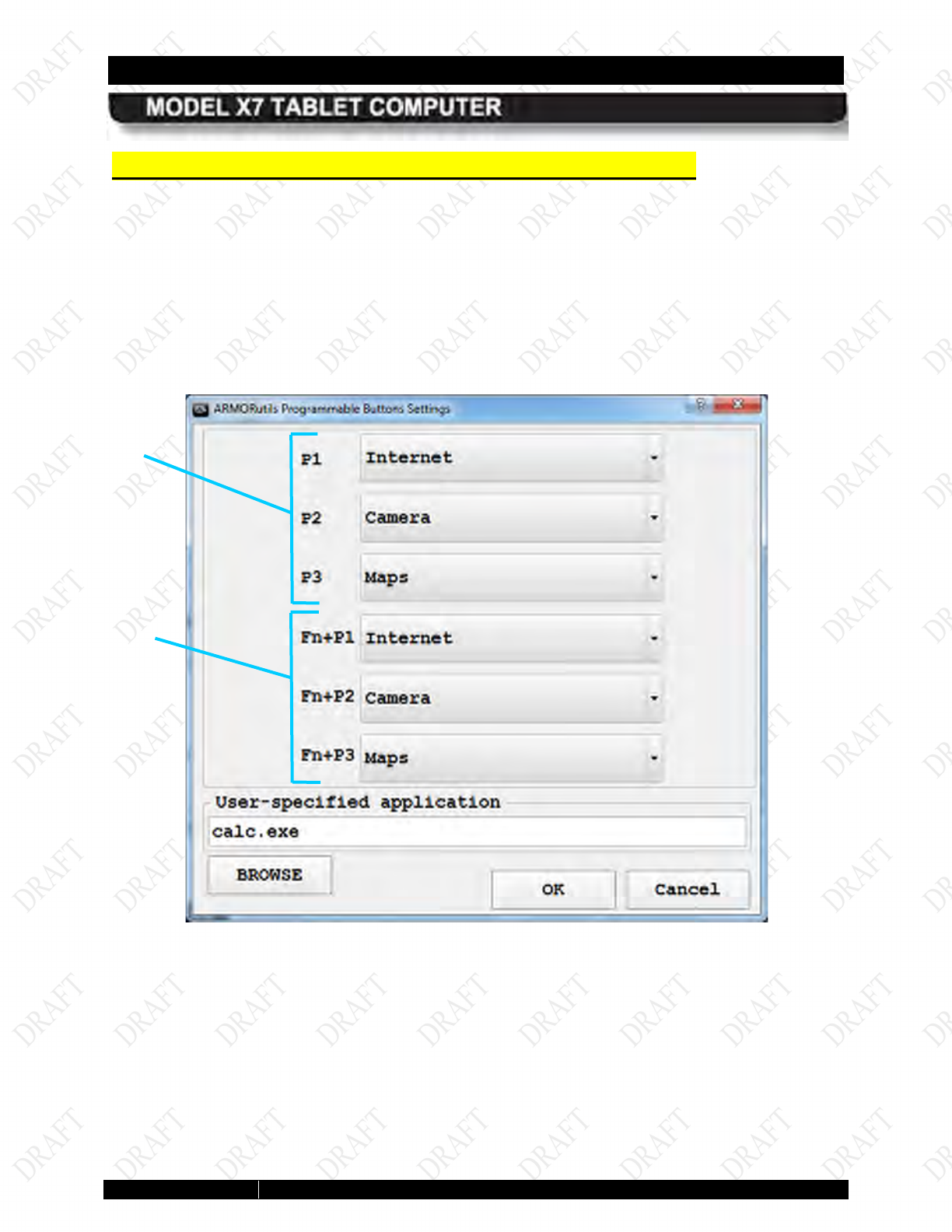
SECTION 5 YOUR ARMOR X7 SOFTWARE PAGE 105
9711-26400-0001
EXPORT CONTROLLED – SEE PAGE 3
Rev -
The PB dialog window is shown in
Programmable Buttons (PBs ) Settings Dialog
Figure 47. It allows you to assign two different functions for
each PB (P1, P2, P3). The first function is activated by pressing and releasing a PB. The
second function is activated by first pressing and releasing the Fn button and then pressing and
releasing a PB (Fn+P1, Fn+P2, Fn+P3). This provides a total of 6 individual functions that can
be activated using the PBs.
The function currently selected for each PB is shown in the field next to the button or Fn combo.
NOTE: For ease of explanation, “PB” will refer to both a single button and a combo button
setting.
Figure 47. ARMORutils Programmable Buttons Settings Page
PB
Fn
COMBO
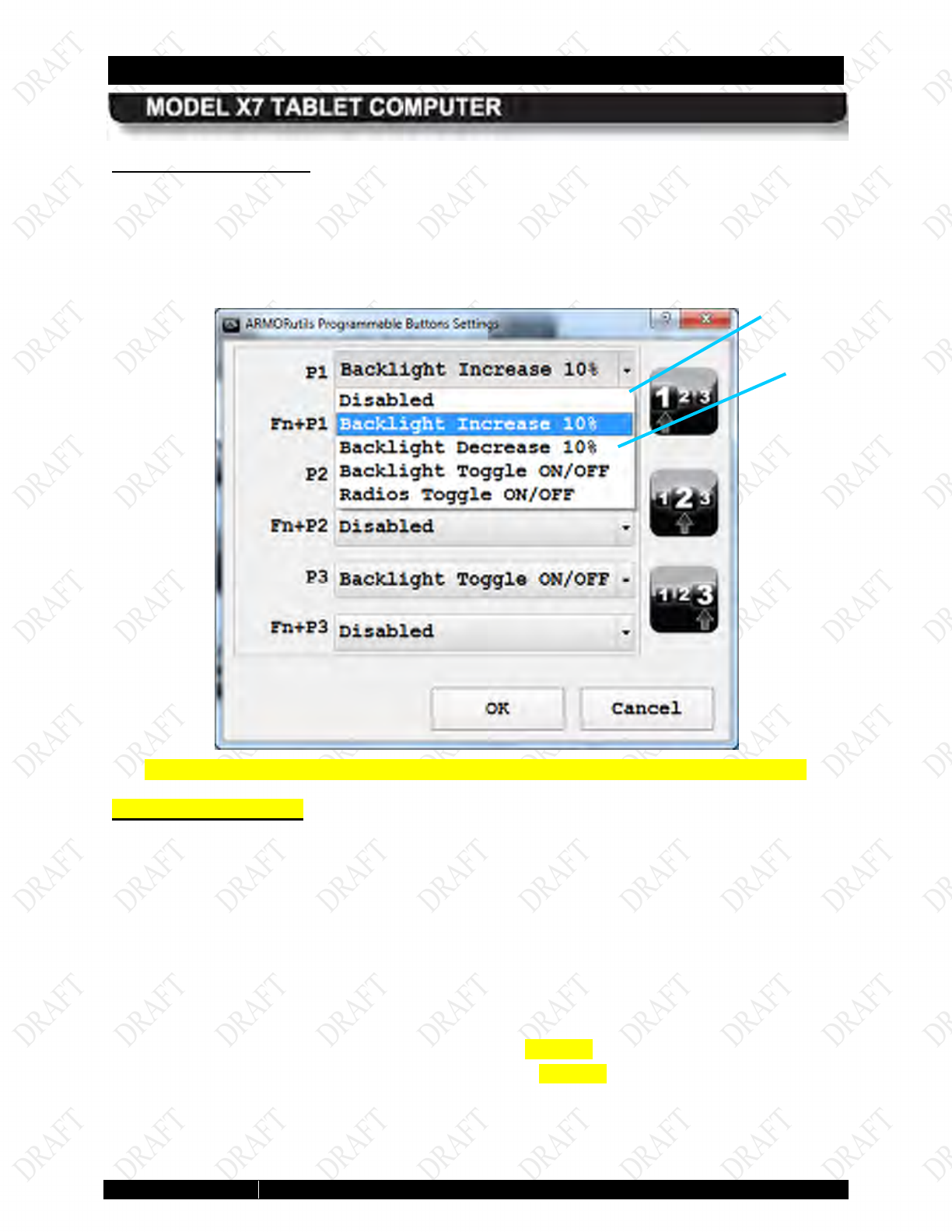
SECTION 5 YOUR ARMOR X7 SOFTWARE PAGE 106
9711-26400-0001
EXPORT CONTROLLED – SEE PAGE 3
Rev -
Click on the menu arrow next to the PB or PB combo and select the desired function, then click
on the OK button to save your setting.
Selecting a Function
Figure 48 shows a menu opened for the Fn +P1 combo.
Click on the menu arrow to the right of the field to access a list of available functions (function
menu), as shown in Figure 48.
Figure 48. ARMORutils Programmable Button Settings Page Menu Options
The currently available programmable functions are listed below along with a brief description of
their purpose (additional functions may be added in future releases of ARMORutils). You can
assign any of these functions to any PB. NOTE: Functions that are not currently supported by
the X7 will be grayed out.
Available Functions
1. Disabled – Disables the button.
2. Backlight Increase 10% - Increases screen and indicator brightness in steps.
3. Backlight Decrease 10% - Decreases screen and indicator brightness in steps.
4. Backlight Toggle ON/OFF – Toggles the screen on and off.
5. Radios Toggle ON/OFF – Toggles all enabled radios on and off.
6. Volume Increase – Increased sound volume in xx steps.
7. Volume Decrease – Decreases sound volume in xx steps.
8. Volume Mute – Toggles volume ON or OFF.
9. Rotate Screen 90 degrees – Rotates the screen 90 degrees clockwise with each press.
10. Video Output Cycle – Not currently supported.
FUNCTION
MENU
MENU
ARROW

SECTION 5 YOUR ARMOR X7 SOFTWARE PAGE 107
9711-26400-0001
EXPORT CONTROLLED – SEE PAGE 3
Rev -
11. Sleep/Hibernate – Depending on the selection in Windows control panel (see…) will
place the tablet in Sleep or Hibernate mode.
12. Launch User-Specified Application – Allows you to select and launch an installed
application.
In each function menu, there is a Set to Default option. Select this option to return a PB’s
programming to its factory default settings. The factory default settings for the X7 are:
Set to Default
P1 - Backlight Increase 10%
P2 - Backlight Decrease 10%
P3 - Backlight Toggle ON/OFF
Fn + P1 - Radios Toggle ON/OFF
Fn + P2 - Disabled
Fn + P3 - Disabled
Currently, you are not able to change the PB default settings. If you need to have the settings
changed, please contact DRS Technical Support.
Launch Us er-Specified Application
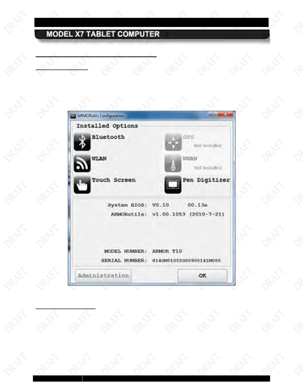
SECTION 5 YOUR ARMOR X7 SOFTWARE PAGE 108
9711-26400-0001
EXPORT CONTROLLED – SEE PAGE 3
Rev -
Configuration Dialog Window
The Configuration Page provides visual confirmation of those wireless radio and display options
that are installed in your X7. For those options that are installed and available, the associated
icons and text will appear in dark contrast. If an option is not installed or available, the icon and
text will be grayed out.
In s talled Options
Figure 49. ARMORutils Configuration Page
Important system information is provided in the bottom panel.
System Information
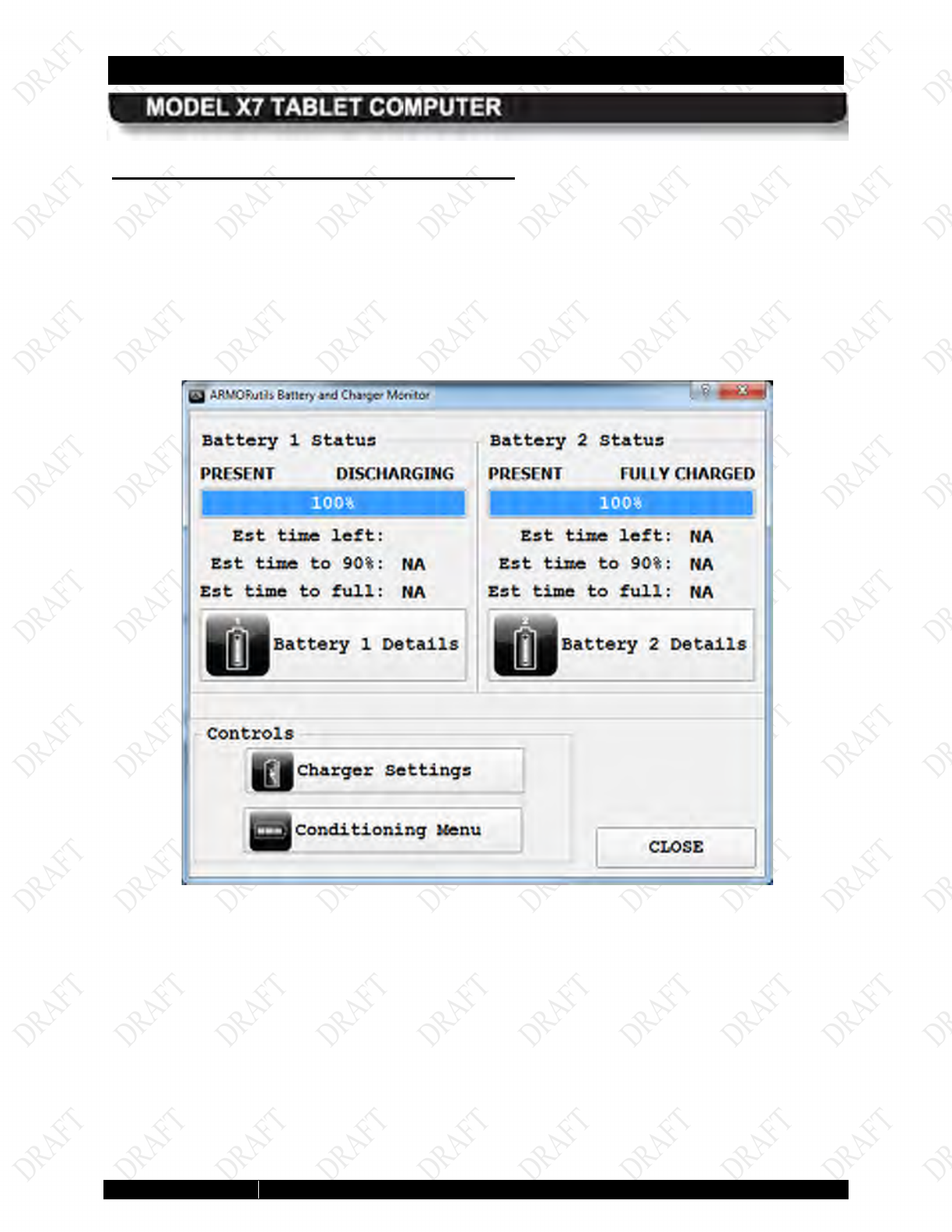
SECTION 5 YOUR ARMOR X7 SOFTWARE PAGE 109
9711-26400-0001
EXPORT CONTROLLED – SEE PAGE 3
Rev -
The Battery Monitor window is shown in
Battery Monitor Dialog Window
Figure 50. This window provides information about:
• Each battery’s current charge level
• Whether or not the battery is charging or discharging
• Its estimated remaining operating time
• The estimated time to reach the next charge level
• The estimated time to reach a full charge.
Figure 50. ARMORutils Battery Monitor Dialog
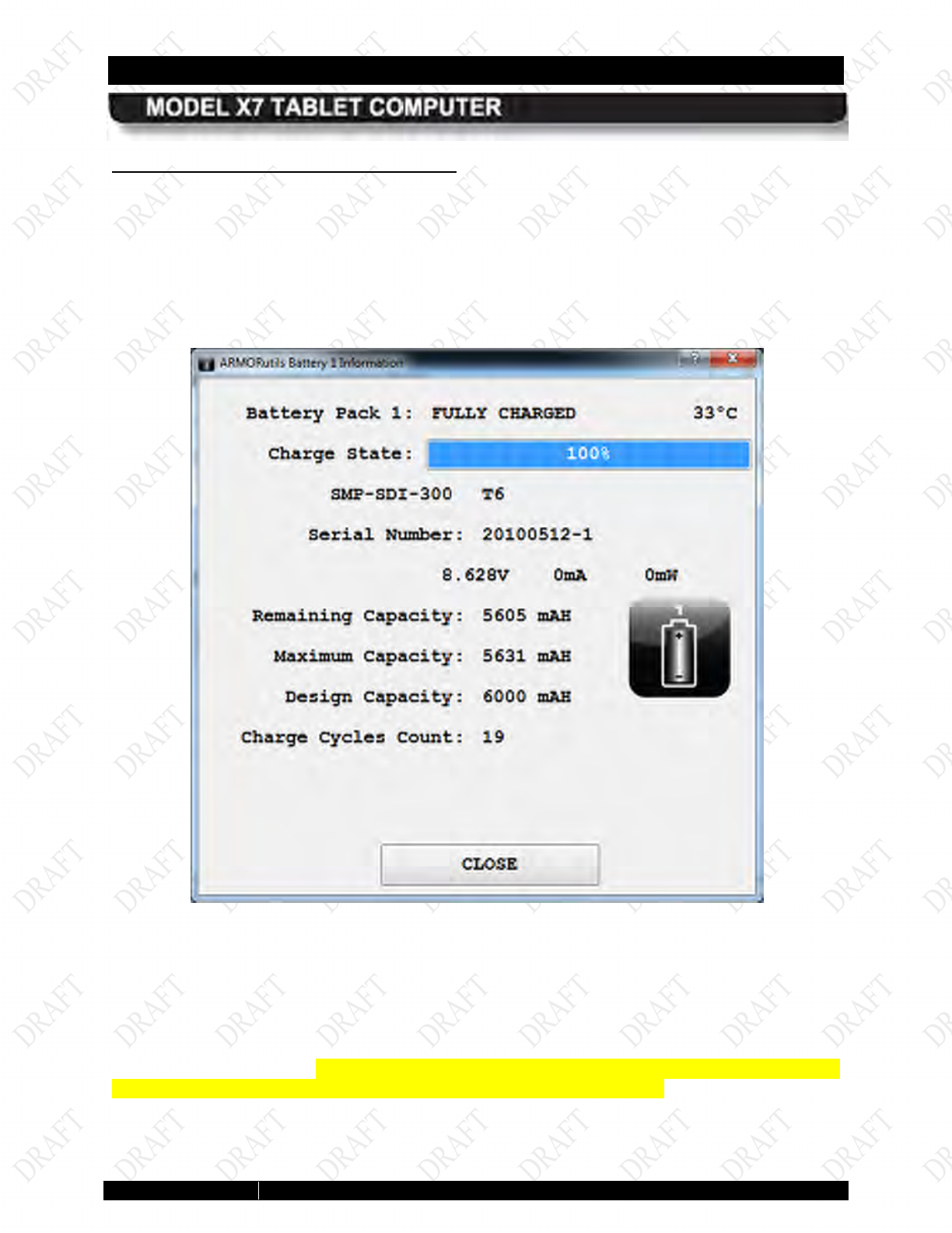
SECTION 5 YOUR ARMOR X7 SOFTWARE PAGE 110
9711-26400-0001
EXPORT CONTROLLED – SEE PAGE 3
Rev -
Click on the Battery 1 Details or Battery 2 Details button (
Battery 1 and 2 Information Buttons
Figure 50) to open a Battery
Information window (example shown in Figure 51). Readings such as percentage of charge,
present capacity, remaining capacity and charge cycle count are updated in real time on this
page.
If the battery needs conditioning, a message will appear at the bottom of the page indicating that
a conditioning is necessary.
Figure 51. ARMORutils Battery Information Window
Remaining Capacity – This is the current charge level expressed in mAh instead of %.
Maximum Capacity – This is the current maximum capacity that the battery can achieve.
Design Capacity – This is the maximum capacity that the battery was designed to hold.
Charge Cycles Count – This is the total number of times the battery has been discharged
below the 30% level and then been recharged to within 15% of maximum.
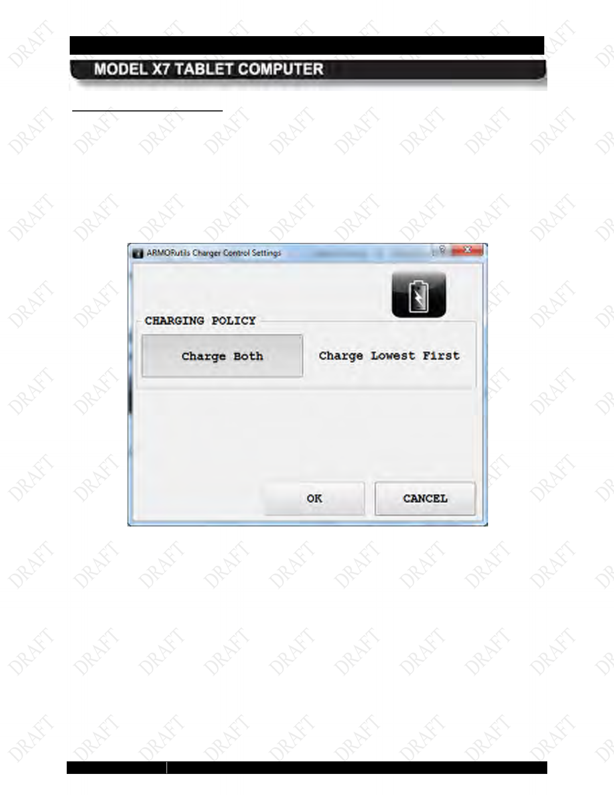
SECTION 5 YOUR ARMOR X7 SOFTWARE PAGE 111
9711-26400-0001
EXPORT CONTROLLED – SEE PAGE 3
Rev -
Click on the Charger Settings button (
Charger Settings Button
Figure 50) to open the Charger Control Settings
window, as shown in Figure 52.
From this window, you can decide what charging policy the system will use when two batteries
are installed. Click on Charge Both to charge both batteries at the same time or Charge
Lowest First to charge the battery with the lowest charge first. The default setting is “Charge
both”.
Click on OK to save the new setting. Select CANCEL to return to the previous setting.
Figure 52. ARMORutils Charger Control Settings Window
.
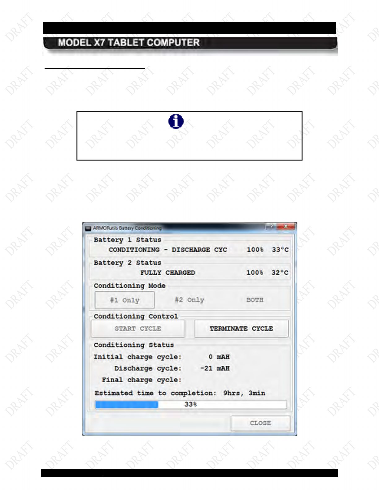
SECTION 5 YOUR ARMOR X7 SOFTWARE PAGE 112
9711-26400-0001
EXPORT CONTROLLED – SEE PAGE 3
Rev -
Click on the Conditioning Menu button (
Conditioning Menu Button
Figure 50) to open the Battery Conditioning window
shown in Figure 53. This window shows the conditioning cycle information for each battery. It
also allows you to select a single battery to condition, or to select both batteries.
NOTE
Conditioning should only be performed if you notice that the levels
reported by Windows or ARMORutils are consistently different
from battery fuel gauge readings.
The conditioning process consists of first charging the battery to a full charge, then drawing the
charge down to its minimum, followed by charging the battery back to a full charge. The entire
conditioning process takes about 4 hours.
Figure 53. Battery Conditioning Dialog
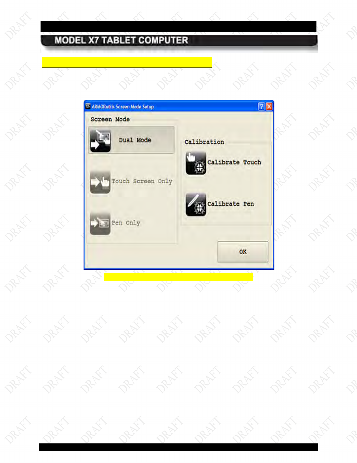
SECTION 5 YOUR ARMOR X7 SOFTWARE PAGE 113
9711-26400-0001
EXPORT CONTROLLED – SEE PAGE 3
Rev -
The Screen Mode dialog is used to select the current display mode and to access calibration
routines for both the touch and pen screens.
Screen Mode Setup Dialog Window
Figure 54. ARMORUtils Screen Setup Dialog

SECTION 5 YOUR ARMOR X7 SOFTWARE PAGE 114
9711-26400-0001
EXPORT CONTROLLED – SEE PAGE 3
Rev -
The Screen Mode dialog allows you to select your desired display mode: Dual mode, Touch
Screen Only mode or Pen Screen Only mode. The default display mode is set to Dual Mode
with both screens enabled.
Screen Mode
Click on the Touch Screen Only button to enable only the touch screen mode; click on Pen
Only to enable only the active pen (digitizer) mode.
You can initiate a calibration routine for each type of screen from this window. Click on either
the Calibrate Touch or Calibrate Pen button and follow the on-screen instructions. If only one
screen mode is enabled, the other calibration option will be grayed out.
Calibration
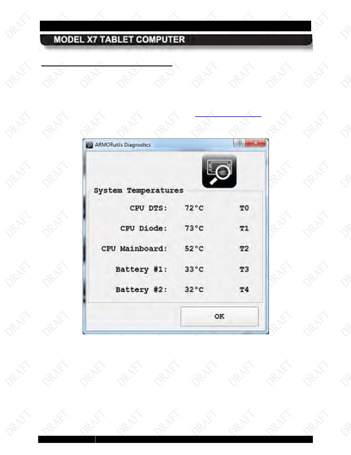
SECTION 5 YOUR ARMOR X7 SOFTWARE PAGE 115
9711-26400-0001
EXPORT CONTROLLED – SEE PAGE 3
Rev -
The Diagnostics dialog window provides internal temperature information that can be used by
DRS to diagnose possible system problems. It displays three internal temperatures of the
processor and one for each battery, as shown in
Diagnos tics Dialog Window
Figure 55. These temperatures vary widely
depending on the operation of the tablet and may not necessarily correlate with outside
(ambient) temperatures.
If you suspect a temperature related problem, contact DRS Technical Support for assistance in
troubleshooting and resolving the problem.
Figure 55. ARMORutils Diagnostics Dialog
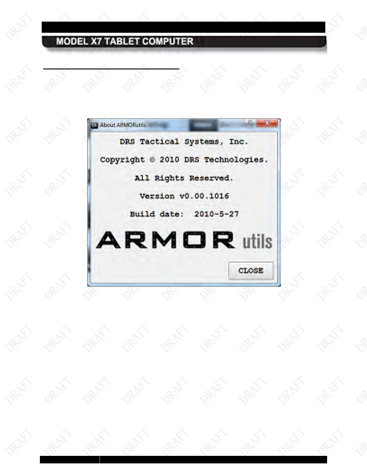
SECTION 5 YOUR ARMOR X7 SOFTWARE PAGE 116
9711-26400-0001
EXPORT CONTROLLED – SEE PAGE 3
Rev -
The About window (
ARMORutils About Window
Figure 56) displays the current version and release date of the ARMORutils
software. It also provides a contact telephone number for the DRS Tactical Systems Technical
Support call center and the internet address to the ARMOR website where you can log on to
access support information.
Figure 56. ARMORutils About Window
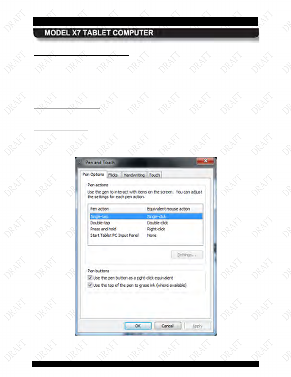
SECTION 5 YOUR ARMOR X7 SOFTWARE PAGE 117
9711-26400-0001
EXPORT CONTROLLED – SEE PAGE 3
Rev -
The Pen and Touch utility is a Windows utility that provides settings that effect how the active
pen works with the pen screen and how a fingertip or passive stylus works with the touch
screen.
Pen and Touch Utility
To open this utility, select Start à Control Panel à Hardware and Sound à Pen and Touch.
The Pen and Touch utility opens, as shown in Figure 57.
The Pen Options tab provides settings that are applicable to the pen screen only.
Pen Options Tab
Highlight an action from the Pen Actions list and click on the Settings button (if active) to open
a settings window, then select options or make adjustments.
Pen Actions Panel
Figure 57. Pen and Touch Utility – Pen Options Tab

SECTION 5 YOUR ARMOR X7 SOFTWARE PAGE 118
9711-26400-0001
EXPORT CONTROLLED – SEE PAGE 3
Rev -
Use the Pen button as a right-click equivalent option – This option is overridden by the pen
button options in the Pen tab of the Pen Tablet Properties utility, regardless of whether it is
checked or not.
Pen Buttons Panel
Use the top of the pen to erase ink option – The erase function is not supported in the X7
from any utility option.
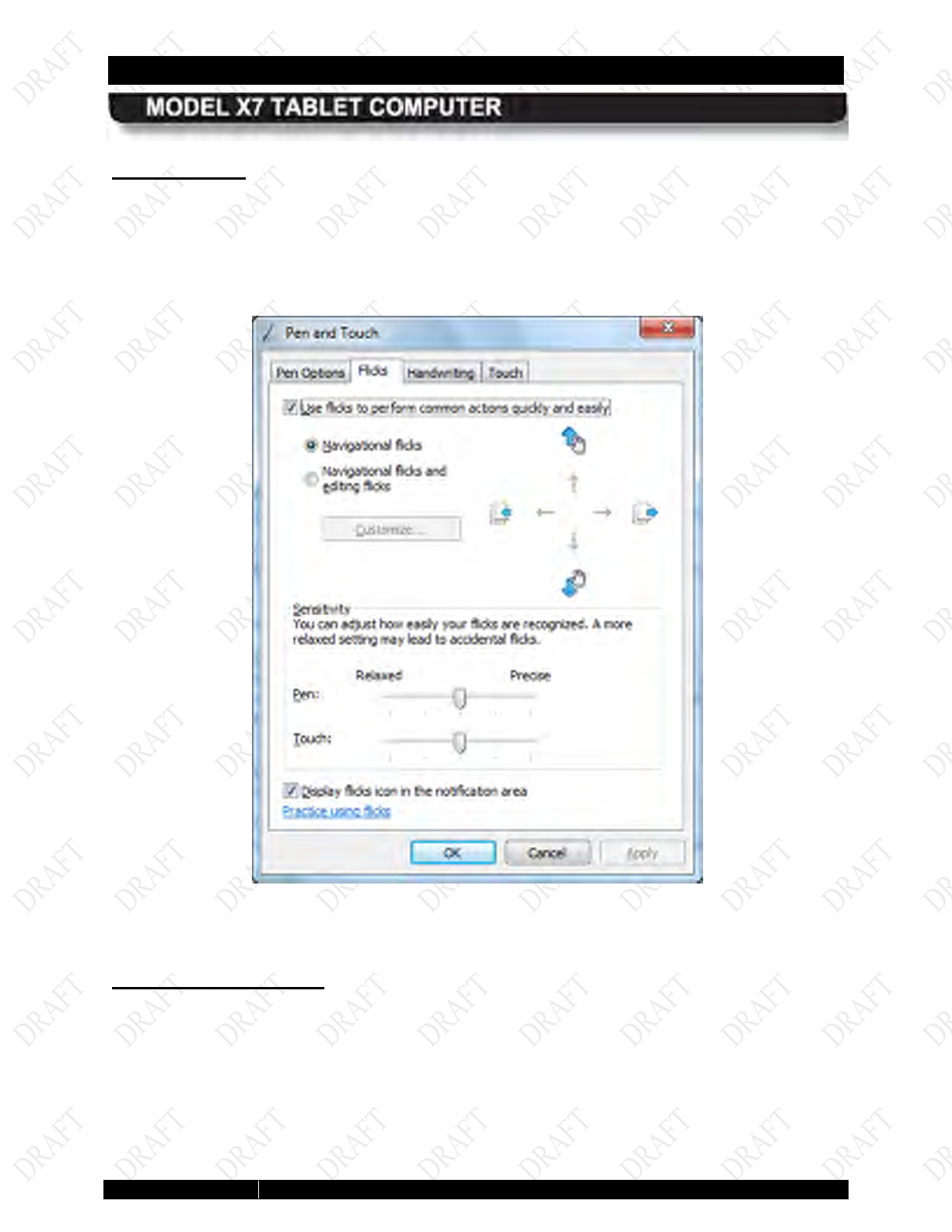
SECTION 5 YOUR ARMOR X7 SOFTWARE PAGE 119
9711-26400-0001
EXPORT CONTROLLED – SEE PAGE 3
Rev -
The Flicks tab provides settings that are applicable to both the pen and touch screens.
Flicks Tab
Flicks are short quick gestures either up, down, left or right that produce common actions such
as scrolling through a document, dragging an object, or opening a folder. Click on the Practice
using flicks link at the bottom of the window to access a tutorial.
Figure 58. Pen and Touch Utility – Flicks Tab
The Handwriting tab provides settings that are applicable to both the pen and touch screens.
Handwriting Tab
The options on this tab allow you to enable or disable the automatic handwriting learning
feature. Click on the “Learn about handwriting personalization link at the bottom of the window
for information about automatic learning and how to train your tablet to recognize your personal
handwriting style.
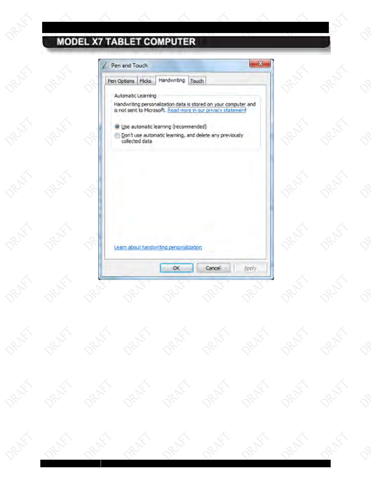
SECTION 5 YOUR ARMOR X7 SOFTWARE PAGE 120
9711-26400-0001
EXPORT CONTROLLED – SEE PAGE 3
Rev -
Figure 59. Pen and Touch Utility – Handwriting Tab
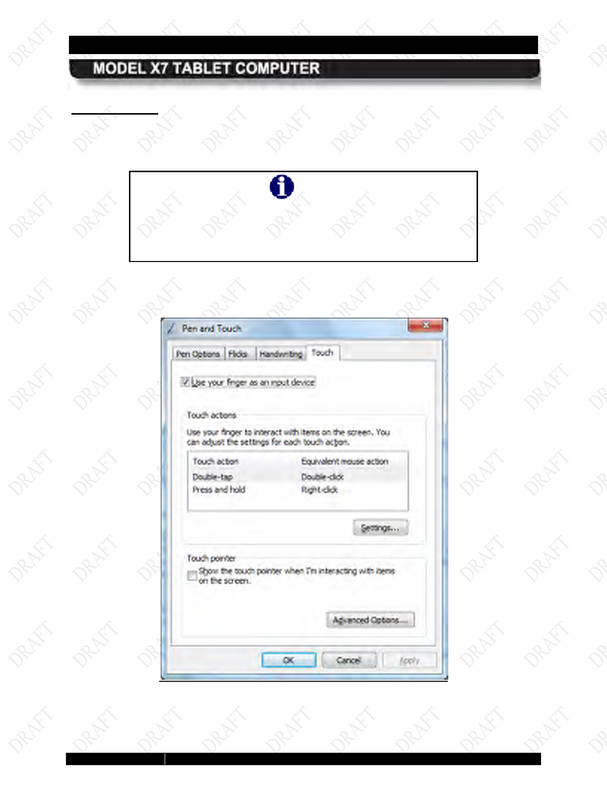
SECTION 5 YOUR ARMOR X7 SOFTWARE PAGE 121
9711-26400-0001
EXPORT CONTROLLED – SEE PAGE 3
Rev -
The Touch tab provides settings that are applicable to the touch screen only. The options on
this tab affect how the pen, or your finger, interacts with the touch screen.
Touch Tab
NOTE
You must have the “Use your finger as an input device” option
checked
to use either your finger or the pen on the touch
screen. If you are in Dual Mode, you can still use the active pen,
but the touch screen will be disabled.
Check the “Use your finger as an input device” option to use either the pen or your finger
with the touch screen.
Figure 60. Pen and Touch Utility – Touch Tab
SECTION 5 YOUR ARMOR X7 SOFTWARE PAGE 122
9711-26400-0001
EXPORT CONTROLLED – SEE PAGE 3
Rev -
Touch Actions
Highlight a touch action and click on the Settings button to open an adjustment window.
Touch Pointer
Select this option to place a pointer at the touch point. A virtual mouse image will also appear
next to the pointer, as shown in Figure 61 . You can then click on the left or right mouse button
to produce the appropriate mouse action.
Click on the Advanced Options button to open a window where you can adjust the touch
pointer position, appearance and behavior.
Figure 61. Touch Tab Virtual Mouse Pointer
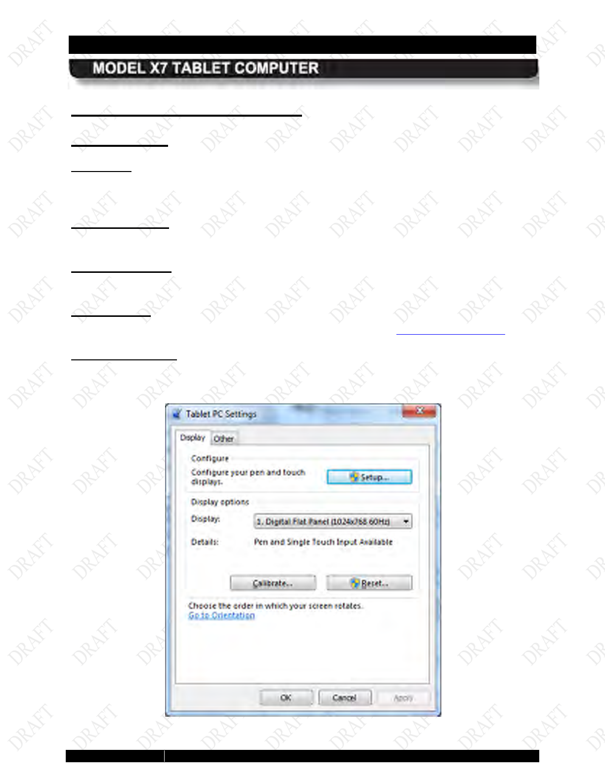
SECTION 5 YOUR ARMOR X7 SOFTWARE PAGE 123
9711-26400-0001
EXPORT CONTROLLED – SEE PAGE 3
Rev -
Tablet PC Settings Utility
Dis play Tab
This function is not used with the X7. Use the ARMORutils Screen Mode dialog to select Pen or
Touch screen mode.
Configure
The X7 does not support a second display so there is only one option.
Dis play Options
Click on the Calibrate button and select Pen input or Touch input to calibrate a screen.
Calibrate Button
This button is used in conjunction with the Calibrate button (refer to
Reset Button
Calibrating the Display)
This option is not supported by the X7.
Go to Orientation
Figure 62. Tablet PC Settings – Display Tab
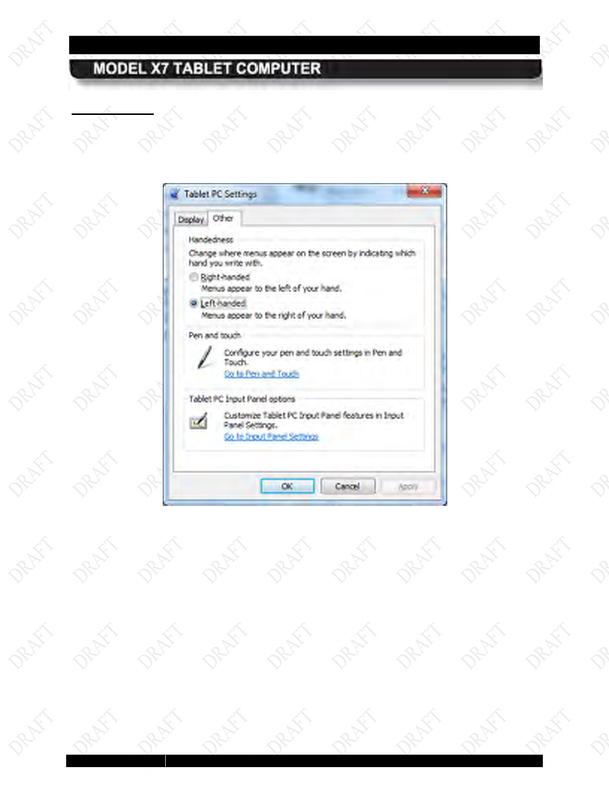
SECTION 5 YOUR ARMOR X7 SOFTWARE PAGE 124
9711-26400-0001
EXPORT CONTROLLED – SEE PAGE 3
Rev -
This tab allows you to change where an on-screen menu appear when you activate the pen or
touch displays so that your hand does not block your view of the menu. For example, if you are
left-handed, check the Left-handed option to have the menus appear to the right of the pointer.
Other Tab
Figure 63. Tablet PC Settings Utility – Other Tab
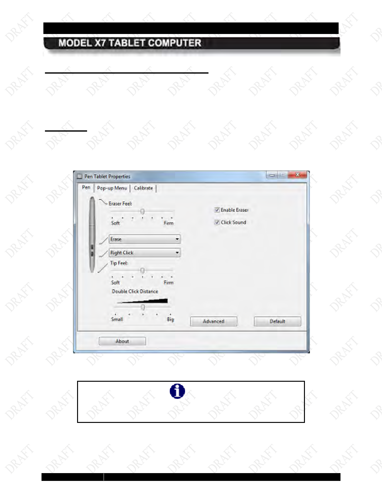
SECTION 5 YOUR ARMOR X7 SOFTWARE PAGE 125
9711-26400-0001
EXPORT CONTROLLED – SEE PAGE 3
Rev -
The following paragraphs briefly describe the purpose and actions of the Pen Tablet Properties
utility. To open the Pen Tablet Properties window, select Start à Control Panel à Hardware
and Sound and click on the Pen Tablet Properties icon to open the Pen Tablet Properties
window shown in
Pen Tablet Properties Utility
Figure 64.
The Pen tab is displayed by default when the Pen Tablet Properties window opens (
Pen Tab
Figure 64 ).
The pen pictured in the tab is a WACOM™ pen that is normally used in advanced drawing
tablets. Its functionality far exceeds what is required for your X7 tablet. Consequently, we have
provided a simpler active pen.
Figure 64. WACOM Pen Tablet Properties Window – Pen Tab
NOTE
The pen that comes with your ARMOR X7 has only one side button
and no eraser function.
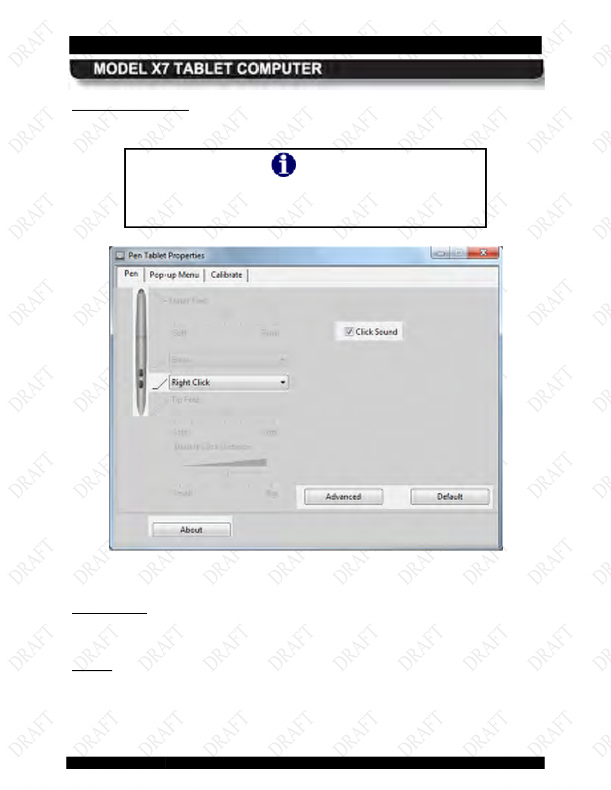
SECTION 5 YOUR ARMOR X7 SOFTWARE PAGE 126
9711-26400-0001
EXPORT CONTROLLED – SEE PAGE 3
Rev -
Figure 65
Supported Options
and Figure 66 highlight those functions and options that are supported by your
ARMOR X7 active pen.
NOTE
Options not supported by the X7 pen are grayed out in Figure 65
and Figure 66
for illustration purposes only. They are not grayed
out on the actual application screen image.
Figure 65. Settings and Options Supported by the ARMOR X7 Active Pen
Check the Click Sound option to enable a clicking sound when you perform an action with the
pen.
Click Sound
The X7 does not support the Erase function.
Eraser
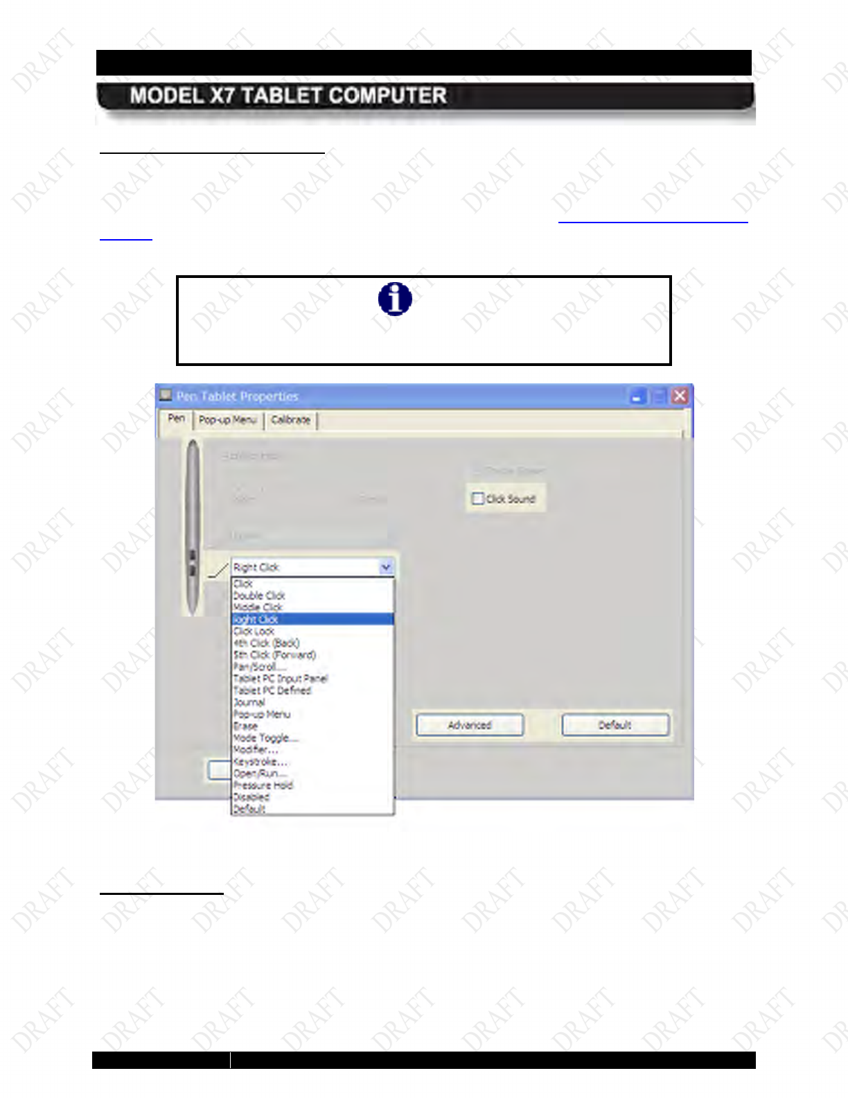
SECTION 5 YOUR ARMOR X7 SOFTWARE PAGE 127
9711-26400-0001
EXPORT CONTROLLED – SEE PAGE 3
Rev -
The side button can be set to perform different functions that are selected from the pull down
menu shown in
Side Button Menu Options
Figure 66. The default function is “Right Click”.
Only the lower button menu is used with the X7 pen. Refer to Explanation of Side Button
Options in the Appendix for a description of each menu option.
NOTE
Some side switch settings may work differently in some software
applications.
Figure 66. Side Button Menu Options
Click on the Default button to return the Pen tab settings to their default values.
Default Button
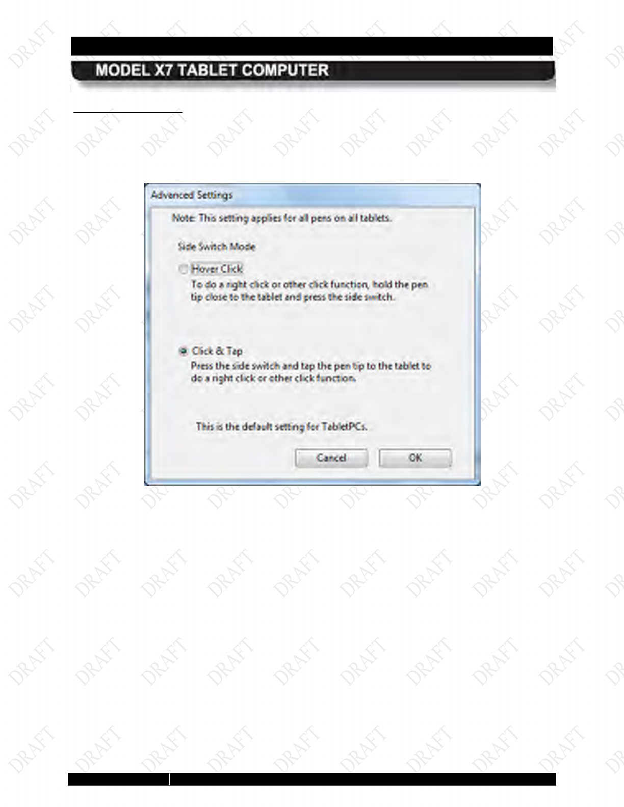
SECTION 5 YOUR ARMOR X7 SOFTWARE PAGE 128
9711-26400-0001
EXPORT CONTROLLED – SEE PAGE 3
Rev -
Click on the Advanced button to open the Advanced Settings window, as shown in
Advanced Button
Figure 67.
The two options in this window allow you to set the way the side switch will be used to perform a
right click action. Click & Tap is the default action.
Figure 67. Pen Tablet Properties - Advanced Settings Window
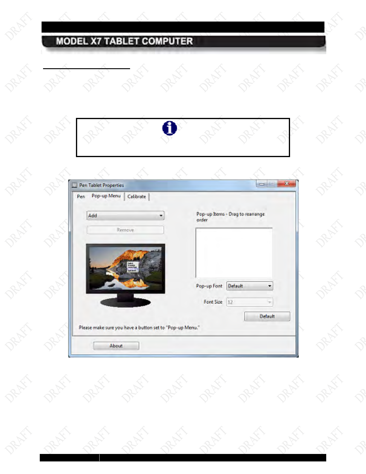
SECTION 5 YOUR ARMOR X7 SOFTWARE PAGE 129
9711-26400-0001
EXPORT CONTROLLED – SEE PAGE 3
Rev -
The Pop-up Menu tab is shown in
Pop-up Menu Tab
Figure 68. This tab allows you to add additional functionality
to the side button. These functions will be displayed in a pop-up menu when the side button is
pressed while in an application or working on the desktop. If only one function has been
selected, only that function will be available.
NOTE
To use the functions set in the pop-up menu, you must select the
“Pop-up Menu” option from the side button menu in the Pen tab.
Figure 68. Pen Tablet Properties – Pop-up Menu Tab
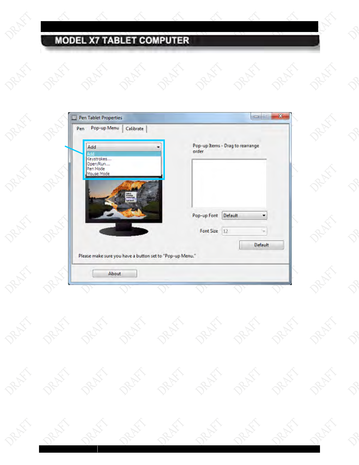
SECTION 5 YOUR ARMOR X7 SOFTWARE PAGE 130
9711-26400-0001
EXPORT CONTROLLED – SEE PAGE 3
Rev -
Click on the down arrow in the Add field to open a list of available functions then select and
configure the desired function. Those functions that are selected will appear in the Pop-up
Items panel to the right of the Add field. Click on the Remove button to delete a function.
When you are using the pen in an application or on the desktop and you press the side button, a
small menu is displayed with the options you have configured.
Figure 69. Pop-up Menu Add Options
OPTIONS
MENU
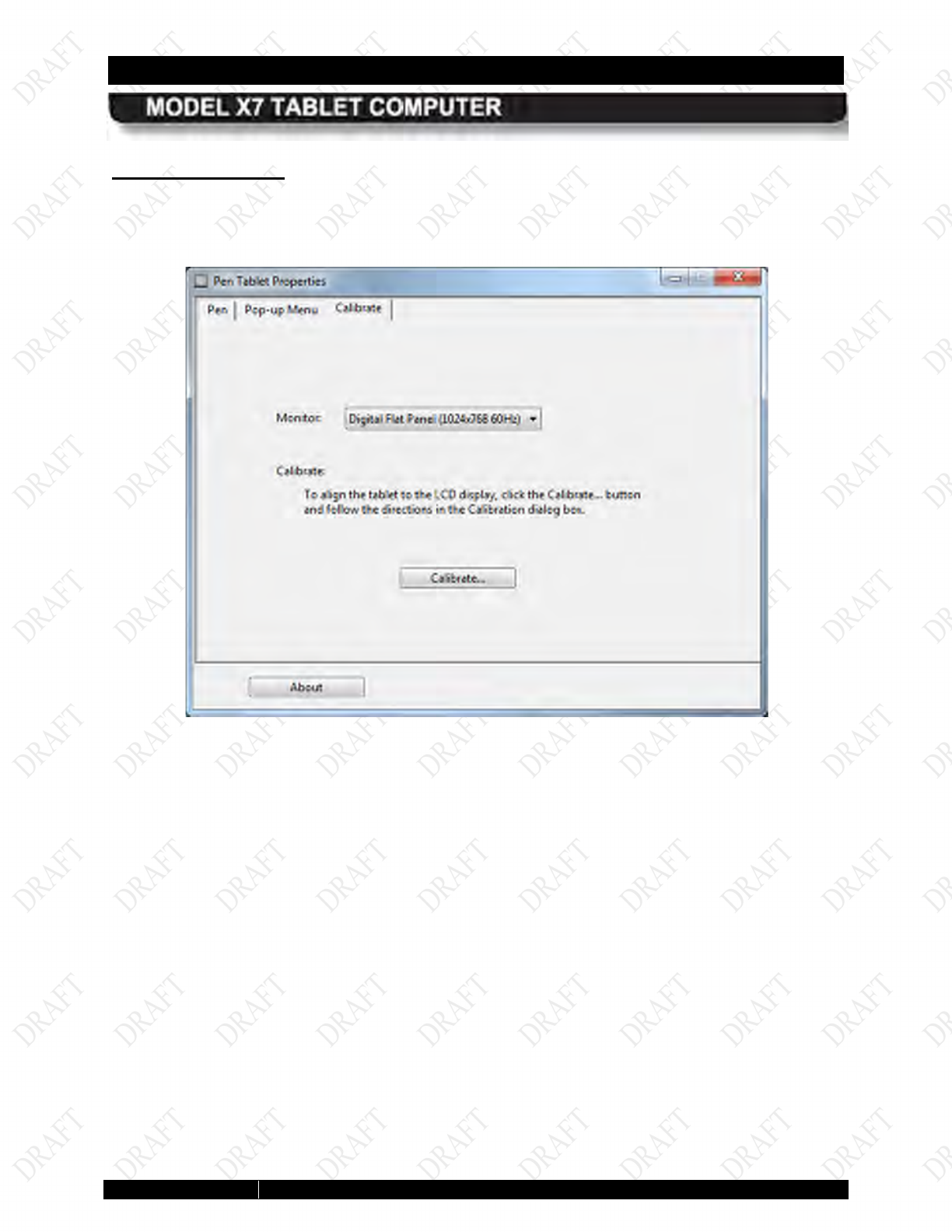
SECTION 5 YOUR ARMOR X7 SOFTWARE PAGE 131
9711-26400-0001
EXPORT CONTROLLED – SEE PAGE 3
Rev -
The Calibrate tab is shown in
Calibrate Tab
Figure 70. Click on the Calibrate button to access the screen
calibration routine. Follow the on-screen instructions.
Figure 70. Pen Tablet Properties Window – Calibrate Tab
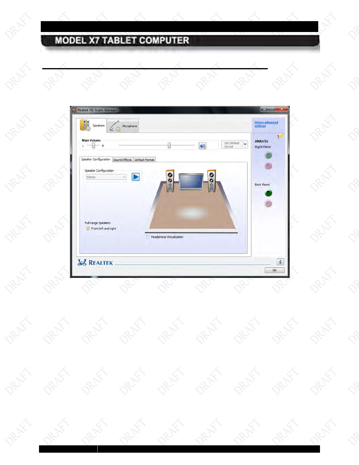
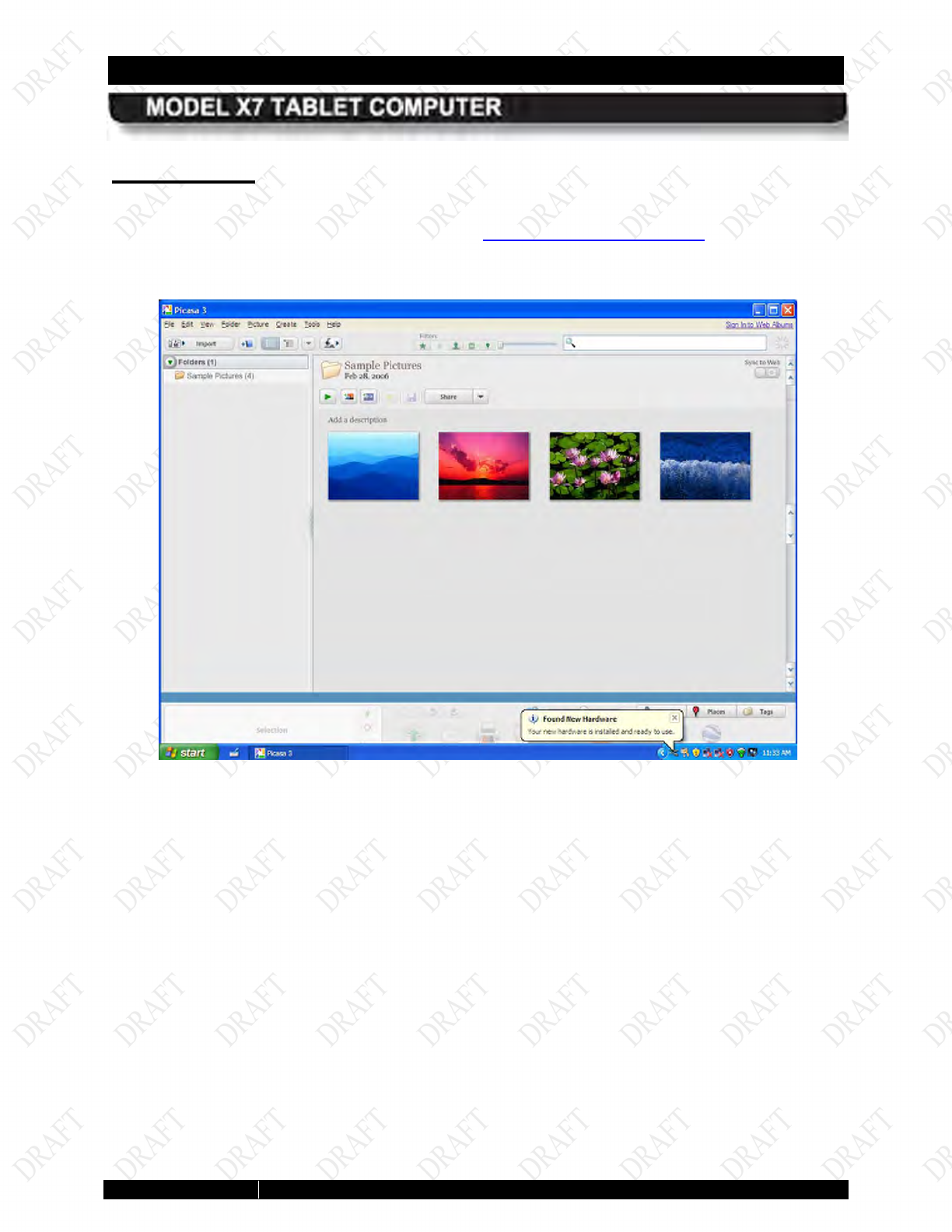
SECTION 5 YOUR ARMOR X7 SOFTWARE PAGE 133
9711-26400-0001
EXPORT CONTROLLED – SEE PAGE 3
Rev -
Picasa 3 is an image capture program that allows you to use the webcam for taking still pictures
and movies and for capturing barcodes. Refer to
Picasa 3®
Capturing Images and Video
for instructions on
how to use this application.
Figure 71. Picasa 3 Image Capture Application
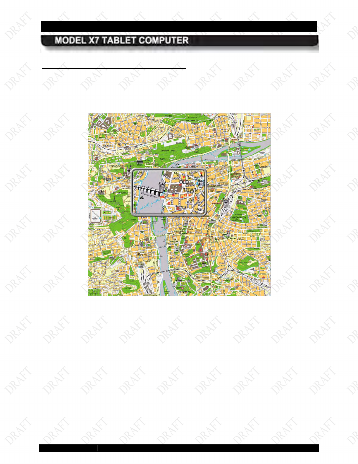
SECTION 5 YOUR ARMOR X7 SOFTWARE PAGE 134
9711-26400-0001
EXPORT CONTROLLED – SEE PAGE 3
Rev -
This handy utility allows you to magnify portions of the screen that are too small to see clearly. It
projects a virtual magnifying glass over a portion of the screen, as shown in
Virtual Magnifying Glass™
Figure 72. Refer to
Using the Screen Magnifier for instructions on how activate and use this application.
Figure 72. Virtual Magnifying Glass Application
SECTION 6 TROUBLESHOOTING PAGE 135
9711-26400-0001
EXPORT CONTROLLED – SEE PAGE 3
Rev -
6. TROUBLESHOOTING
This section addresses only those problems that can be corrected by replacing a removable
component such as a hard drive or battery, by replacing or reseating an external cable, or by
changing a configuration setting. Any other failure will require the tablet be returned to DRS
Tactical Systems.
For each problem that occurs with your ARMOR X7 computer, there are specific steps that will
isolate the problem to a failed component or to a configuration option that may be set
incorrectly. In many cases, a single action step will isolate or correct the problem. In others, a
troubleshooting flowchart with multiple actions may be needed.
Table 20
Determining the Problem
lists some possible symptoms pointing to problems with your ARMOR X7. It then
provides actions to correct a problem. In some cases, you will be directed to a troubleshooting
flow chart to further isolate the problem.
Use the Symptom and Problem Area columns to identify the problem you are having, then
follow any directions in the Action column or go to the indicated troubleshooting flowchart to
begin troubleshooting.
Table 20. ARMOR X7 Trouble Symptoms
SYMPTOM PROBLEM AREA ACTION FLOWCHART
Tapping with the pen
or
stylus does not
select or activate an
option, or the pointer
does not align with
stylus or pen point.
Display (touch or
pen screen) 1. Follow the instructions in
Error! Reference source
not found. or Error!
Reference source not
found. to calibrate the
screen. Repeat up to 5
times if necessary.
2. If screen still does not
calibrate correctly, send
tablet in for repair.
Backlight goes on
and off. Display 1. Default the BIOS.
2. If not fixed, flash H8.
3. If not fixed, send tablet in
for repair.
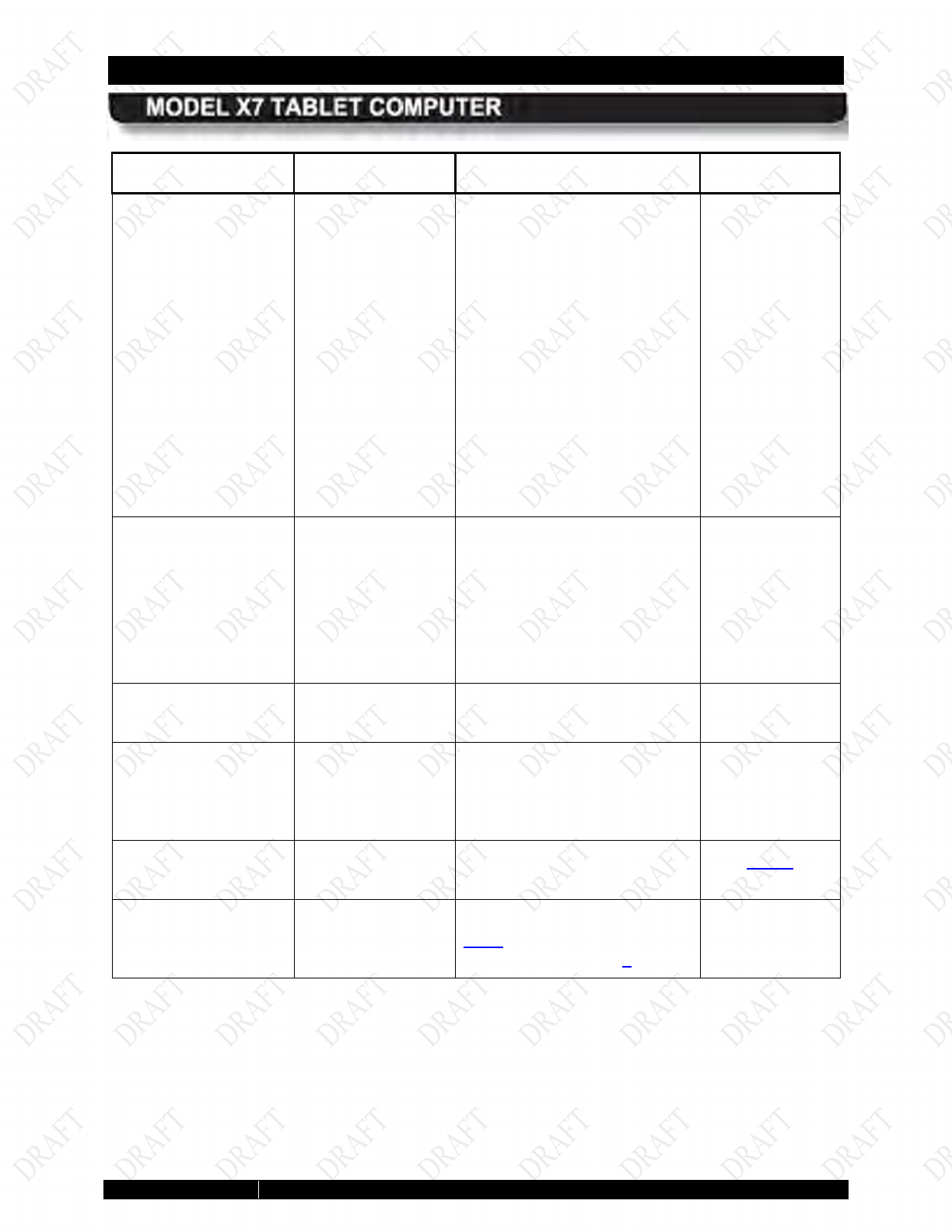
SECTION 6 TROUBLESHOOTING PAGE 136
9711-26400-0001
EXPORT CONTROLLED – SEE PAGE 3
Rev -
SYMPTOM PROBLEM AREA ACTION FLOWCHART
Pen does not right-
click
when held
against the screen.
Display 1. Select Start
à
Control
Panel
à
Hardware and
Sound
à
Pen and
Touch.
2. Highlight the Press and
hold option in the Pen
Actions panel and click on
Settings.
3. Ensure the Enable press
and hold for right
clicking option is
checked.
4. If problem is not fixed,
replace pen.
Pen does not right
click when side
button is pressed
(default setting).
Display 1. Select Start
à
Control
Panel
à
Hardware and
Sound
à
Pen Tablet
Properties.
2. Verify/change setting to
Right Click in bottom side
button menu.
Pen not working in
center of display. Display Send tablet in for repair.
Pen opens and
closes folders and
programs without
touching screen.
Display Send tablet in for repair.
Tablet will not
recognize a battery. Battery TS-04
Battery will not hold a
charge. Battery Perform the procedure in
What to Do for Overly-
Discharged Batteries
.
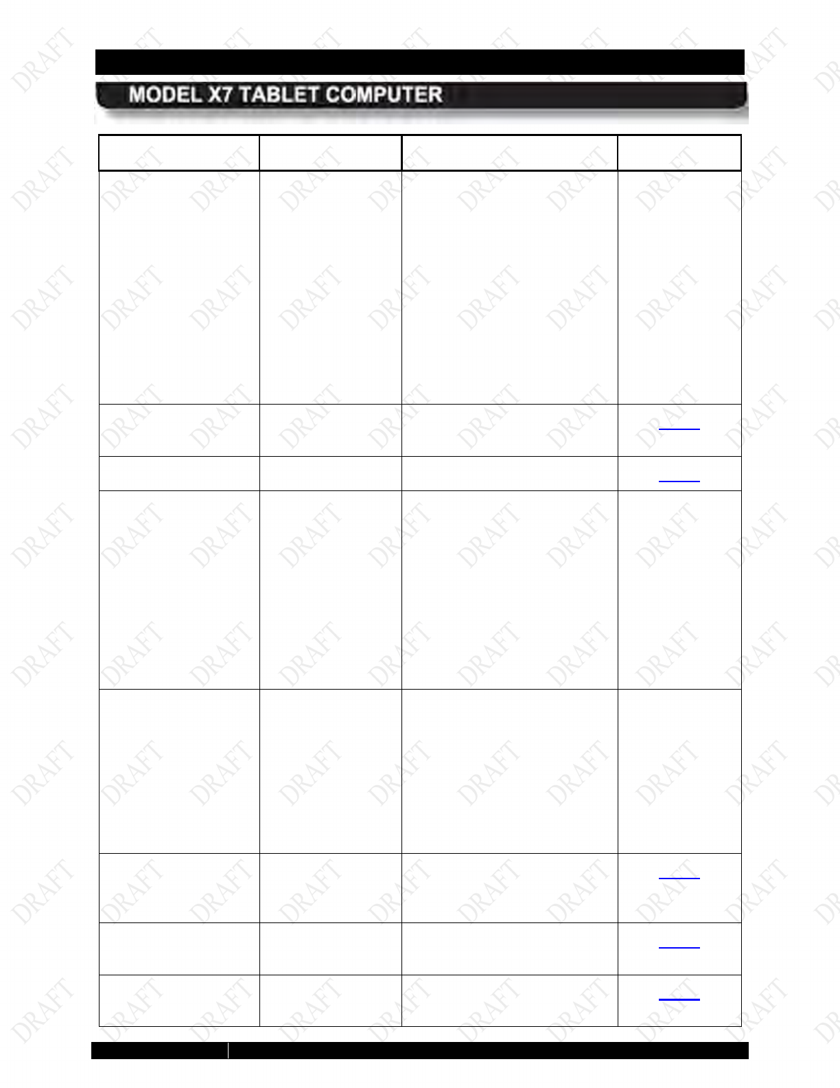
SECTION 6 TROUBLESHOOTING PAGE 137
9711-26400-0001
EXPORT CONTROLLED – SEE PAGE 3
Rev -
SYMPTOM PROBLEM AREA ACTION FLOWCHART
Charging/Fault LED
(indicator panel) is on
steady red.
Power S
ystem or
Battery
The red LED will turn off
when the fault condition is
removed.
Try removing external power
(if connected).
If the fault occurs on batteries
only, connect external power
and remove each battery one
at a time.
If the fault persists, return the
tablet for repair.
Tablet will not power
up. Power
System or
Battery TS-01
Tablet is locked up. Run TS-05
Screen rolls, flashes,
and then tablet
freezes up.
Run 1. Remove both batteries
and connect AC adapter.
2. Reboot the tablet.
3. If tablet works normally,
reinstall one battery at a
time and reboot until
problem reoccurs.
4. Replace one or both
batteries as applicable.
Tablet shuts down on
its own. Run 1. Start
à
Control Panel
à
Power Options and
check if the computer has
a shut down setting to
save power.
2. If no shut down option is
enabled, return tablet for
repair.
Tablet will not start
boot process. Power
ok.
Boot Up TS-02
Tablet will not boot
into Windows. Boot Up TS-03
Cannot connect to a
wireless network. Wireless TS-06
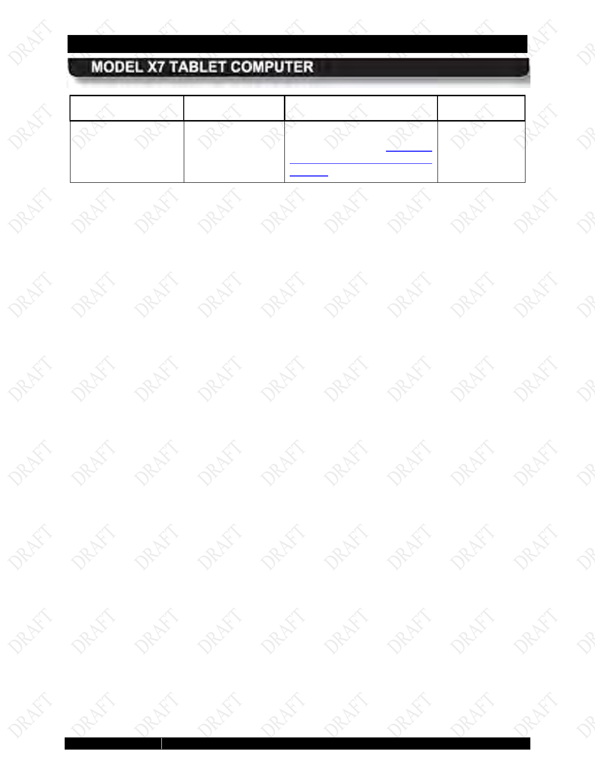
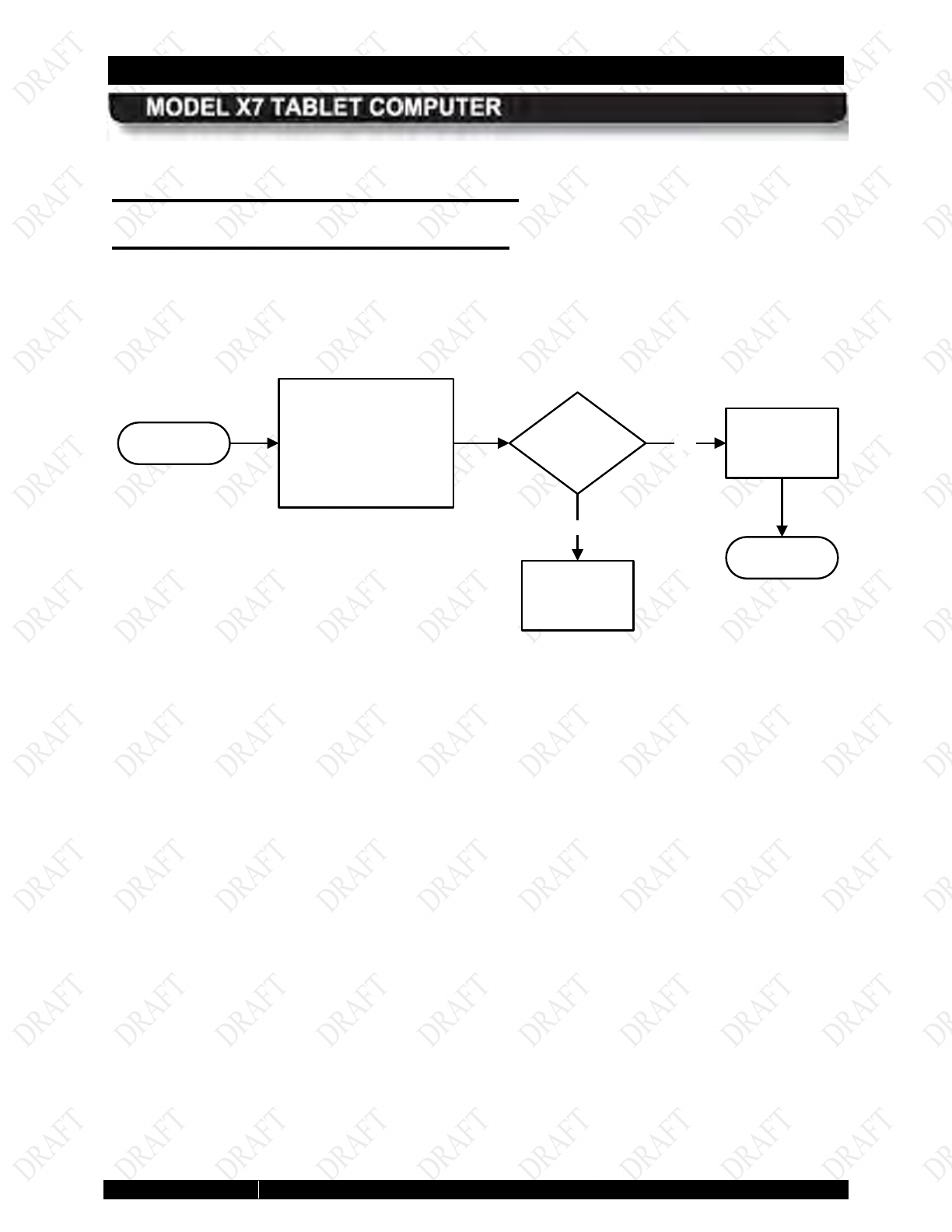
SECTION 6 TROUBLESHOOTING PAGE 139
9711-26400-0001
EXPORT CONTROLLED – SEE PAGE 3
Rev -
Troubleshooting Flowcharts
TS-01 Tablet will not power up
Start
1. Remove both
batteries and connect
tablet to docking
station or connect AC
adapter.
2. Attempt to power up.
Does tablet
power up? Yes
Exit
Replace
batteries.
No
Send tablet in
for repair.
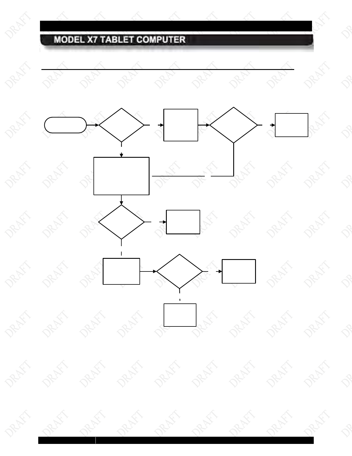
SECTION 6 TROUBLESHOOTING PAGE 140
9711-26400-0001
EXPORT CONTROLLED – SEE PAGE 3
Rev -
TS-02 Tablet will not start boot process. Power is ok
Start Is tablet
docked? Yes Undock tablet
and attempt to
boot up.
No
1. Remove both
batteries and connect
tablet to docking station
or connect DC power
supply.
2. Attempt to boot up.
Did tablet
boot up? Yes
No
Send tablet
in for repair.
Does
tablet
boot up? Yes
No
Replace
batteries.
Temporarily
replace HD with
another HD.
Does
tablet
boot up? Yes
No
Re-image
HDD.
Send tablet
in for repair.
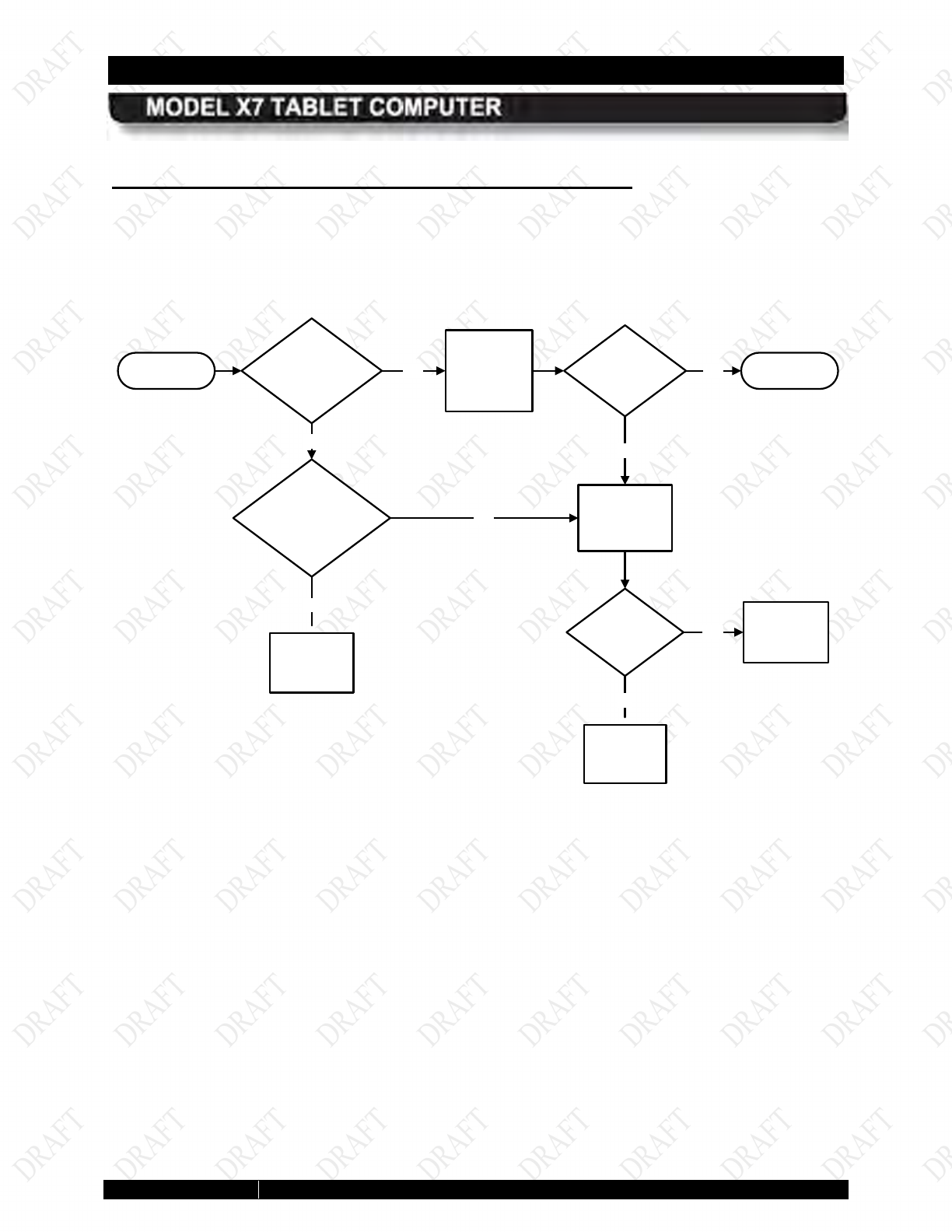
SECTION 6 TROUBLESHOOTING PAGE 141
9711-26400-0001
EXPORT CONTROLLED – SEE PAGE 3
Rev -
TS-03 Tablet will not boot into Windows
Does boot
process halt at
white flashing
cursor?
Yes Verify correct
boot device in
BIOS.
No
Does tablet
boot up?
No
Does tablet boot to
blue screen or does
screen go black? Yes
No
Temporarily
replace HD with
another HD.
Does
tablet
boot up? Yes
No
Send tablet
in for repair.
Send tablet
in for repair.
Exit
Yes
Re-image or
replace HDD.
Start
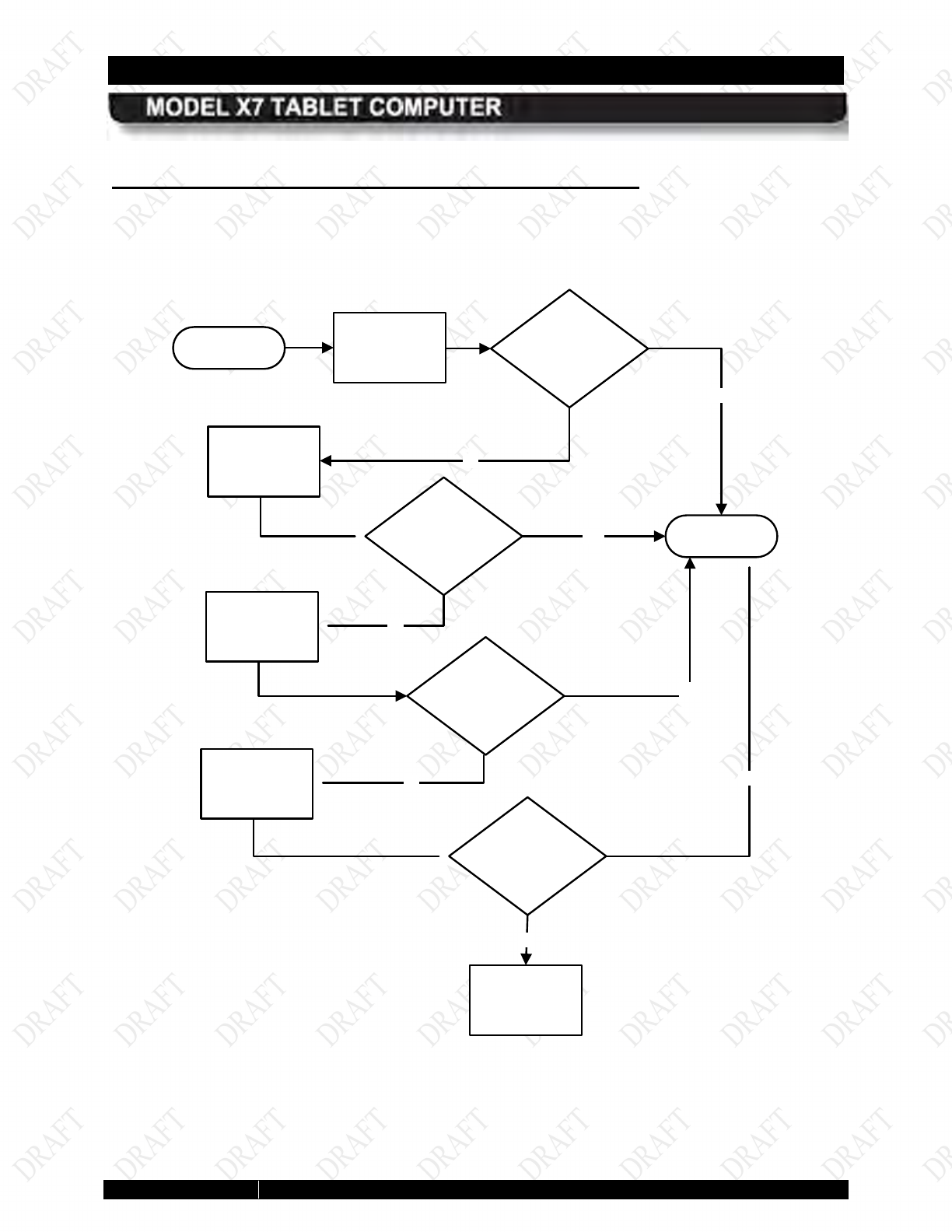
SECTION 6 TROUBLESHOOTING PAGE 142
9711-26400-0001
EXPORT CONTROLLED – SEE PAGE 3
Rev -
TS-04 Tablet will not recognize a battery
Start Does tablet
recognize
battery?
Yes
Exit
No
Recharge/
replace the
battery.
Flash the bios
Send tablet in
for repair.
Does tablet
recognize
battery?
Yes
No
Re-image/
replace the
hard drive.
Does tablet
recognize
battery?
No
Yes
No
Flash H8
Does tablet
recognize
battery?
Yes
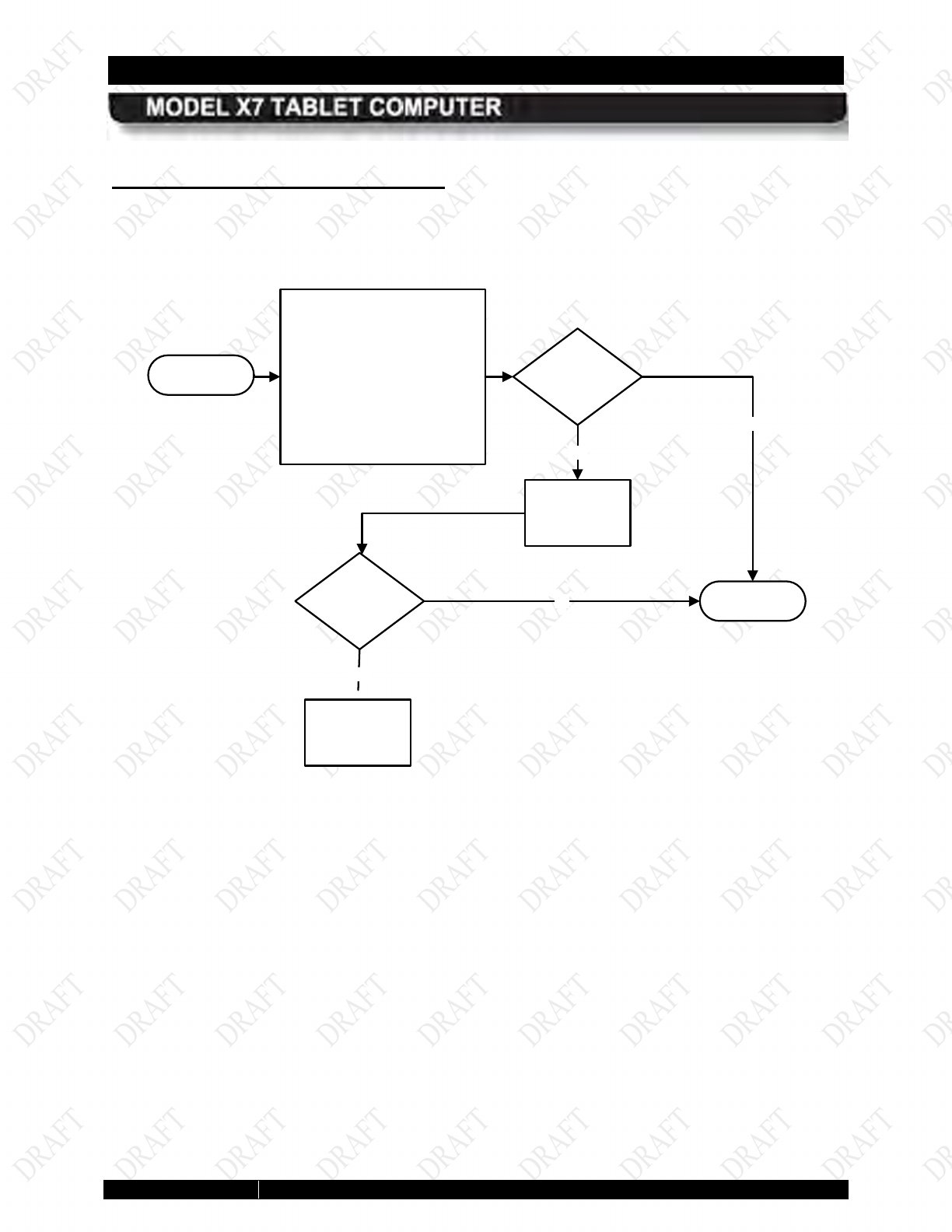
SECTION 6 TROUBLESHOOTING PAGE 143
9711-26400-0001
EXPORT CONTROLLED – SEE PAGE 3
Rev -
TS-05 Tablet is locked up
Start
1. Shut down tablet.
2. Disconnect external
power.
3. Remove both batteries and
allow tablet to sit un-
powered for 5 minutes.
4. Re-insert batteries and/or
connect external power.
5. Reboot tablet.
Does tablet
Lock up?
No
Exit
Yes
Re-image/
replace HD.
Does tablet
Lock up?
No
Yes
Send tablet
in for repair.
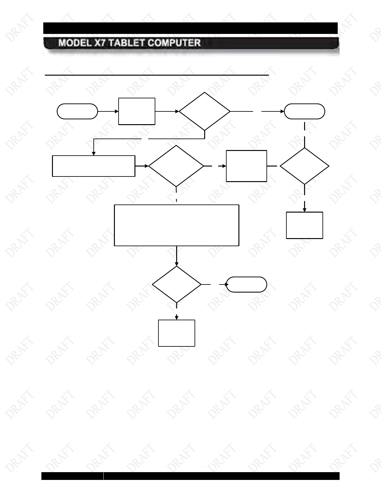
SECTION 6 TROUBLESHOOTING PAGE 144
9711-26400-0001
EXPORT CONTROLLED – SEE PAGE 3
Rev -
TS-06 Cannot connect to wireless network
Shut down and
reboot the
tablet.
Does tablet
Connect to
network?
No
Click on Start à Control Panel à
Network and Sharing Center.
Is a
red “X” present on
a connection
icon?
No
Yes
1. Click on Troubleshoot Problems.
2. Select Network Adapter.
3. Click on Next.
4. Select the network adapter to troubleshoot
5. Follow the on-screen instructions.
5. Reboot the tablet.
Exit
Yes
Start
Send tablet in
for repair.
Does tablet
Connect to
network?
No
Open
ARMORUtils and
click on the
Wireless Setup
option.
Exit
Yes
Send tablet in
for repair.
Is the
problem radio
disabled?
No
Yes

SECTION 6 TROUBLESHOOTING PAGE 145
9711-26400-0001
EXPORT CONTROLLED – SEE PAGE 3
Rev -
This Page Intentionally Left Blank
SECTION 7 MAINTAINING YOUR ARMOR X7 PAGE 147
9711-26400-0001
EXPORT CONTROLLED – SEE PAGE 3
Rev -
7. MAINTAINING YOUR ARMOR X7
The solid state drive is located in the rear compartment in the back of the computer, as shown in
Removing and Replacing the Solid State Drive
Figure 73. Follow the procedure in Table 21 to remove and replace the drive.
CAUTION!
Do not remove the rear compartment cover while the unit is
powered up as internal voltages will be exposed to possible short
circuit.
CAUTION!
Circuit boards containing electrostatic discharge (ESD) sensitive
devices are exposed in this compartment. Static-free handling is
required to prevent possible damage to the components.
NOTE
The solid state
drive should only be removed or installed by a
qualified technician in a controlled environment.
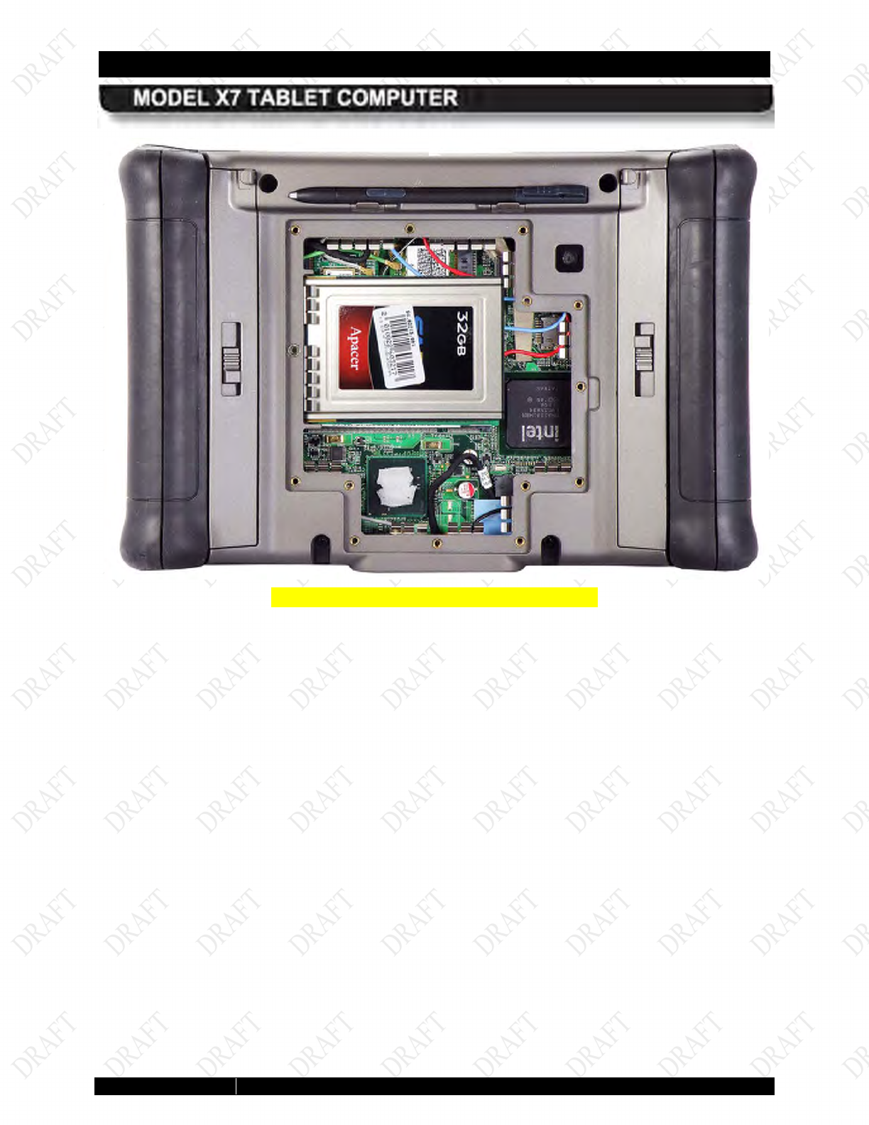
SECTION 7 MAINTAINING YOUR ARMOR X7 PAGE 148
9711-26400-0001
EXPORT CONTROLLED – SEE PAGE 3
Rev -
Figure 73. X7 Solid State Drive Location
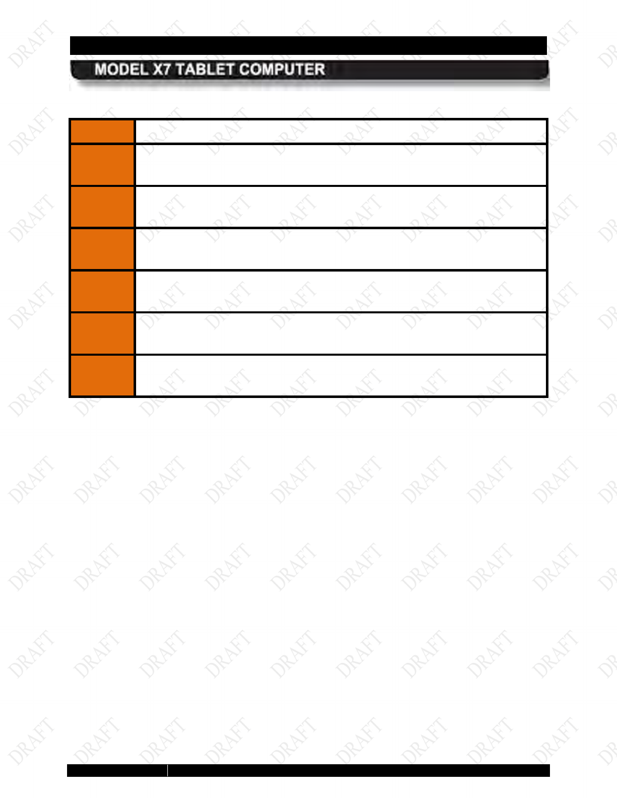
SECTION 7 MAINTAINING YOUR ARMOR X7 PAGE 149
9711-26400-0001
EXPORT CONTROLLED – SEE PAGE 3
Rev -
Table 21. Remove and Replace the Solid State Drive
STEP ACTION
1. Power down the computer and disconnect any external power.
2. Place the computer face down on a clean surface and remove 14 Philips screws
from the cooling register/cover then remove the cover.
3. Lift up on the drive and carefully disconnect it from the computer.
4. Insert the replacement drive.
5. Replace the back cover and secure with the 14 Philips screws.
6. Torque each screw to 2.8 kg-cm (2.4 in-lb).
SECTION 7 MAINTAINING YOUR ARMOR X7 PAGE 150
9711-26400-0001
EXPORT CONTROLLED – SEE PAGE 3
Rev -
Refer to
Removing and Replacing the Batteries
Table 22 and Figure 74 to remove and replace a battery.
CAUTION!
Only one battery at a time can be removed
and replaced during
operation without causing system shutdown and possible loss of
data. Connect external power first before removing both batteries.
Table 22. Remove and Replace a Battery
STEP ACTION
1.
Push in on the battery button and slide the battery release to unlock the battery.
Lift the battery away from the computer case.
2.
To install a battery, place the flat surface of the battery on the battery bay with the
locking slots facing toward the battery latch.
3. Slide the
battery toward the computer until the locking bar engages and the
battery is flush against the compartment wall. Press firmly until the battery locks in
place.
4.
Ensure the battery latch returns to the locked position, as shown in Figure 74.
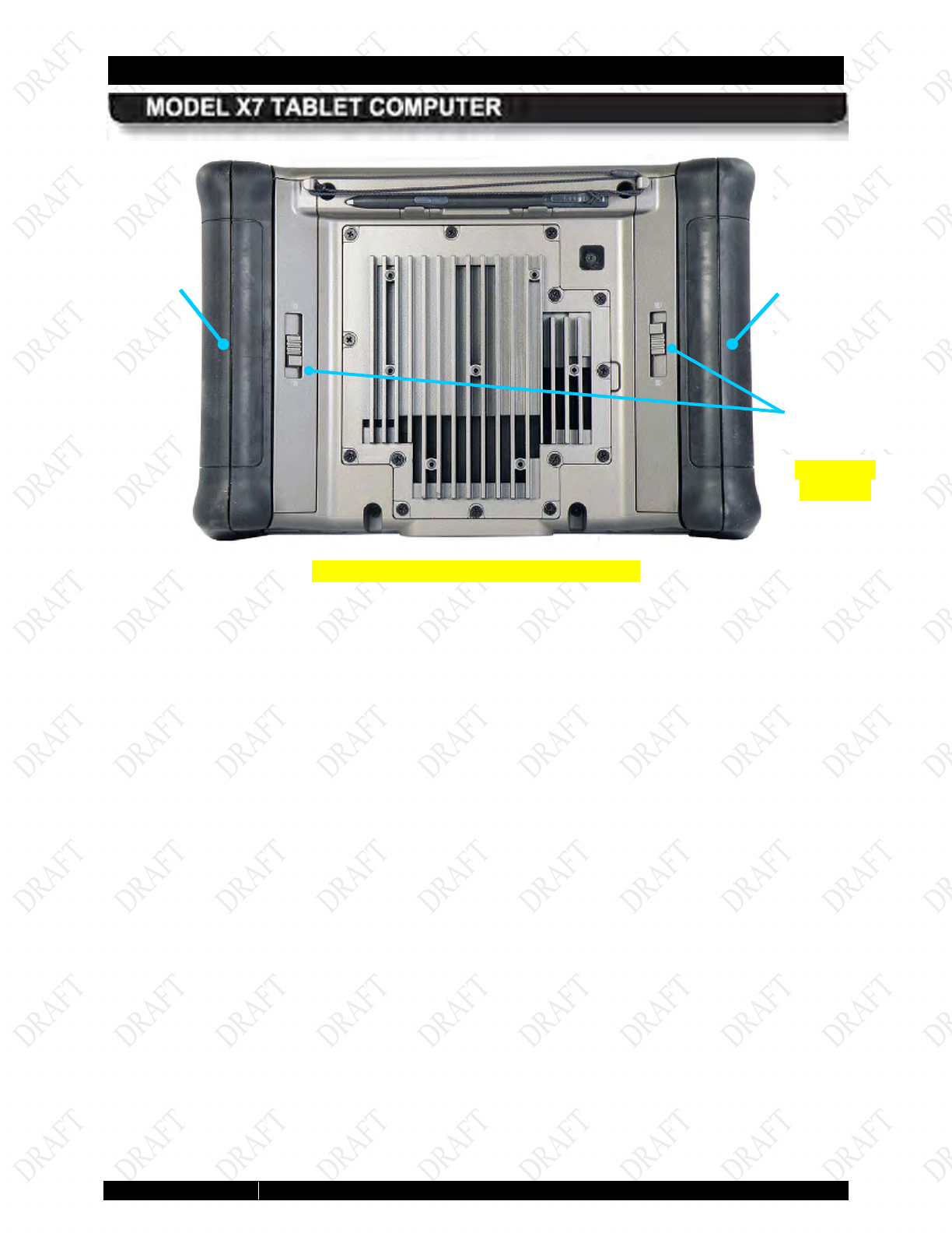
SECTION 7 MAINTAINING YOUR ARMOR X7 PAGE 151
9711-26400-0001
EXPORT CONTROLLED – SEE PAGE 3
Rev -
Figure 74. X7 Battery Pack Locations
BATTERY
RELEASE
BATTERY
#2
BATTERY
#1
BATTERY
BUTTON
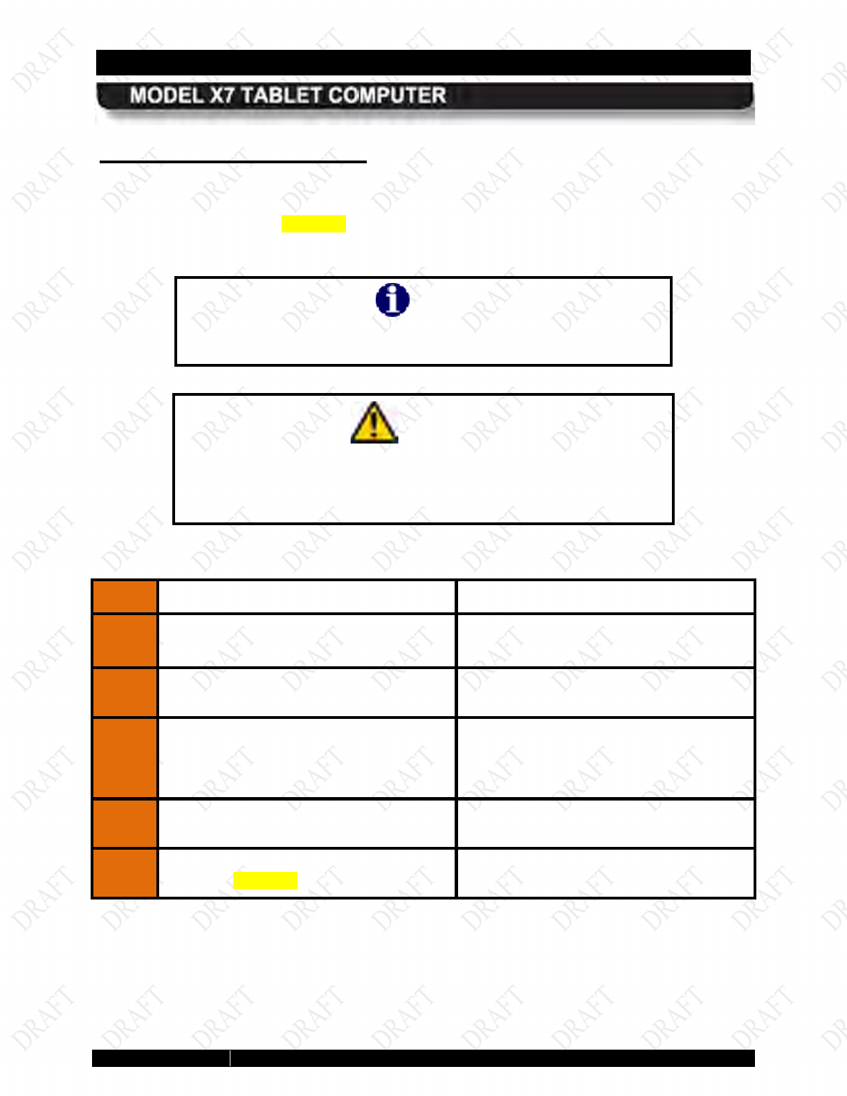
SECTION 7 MAINTAINING YOUR ARMOR X7 PAGE 152
9711-26400-0001
EXPORT CONTROLLED – SEE PAGE 3
Rev -
Before you can activate and use your WWAN radio, a valid SIM card from your network service
provider needs to be installed. The SIM card is installed in a socket located inside the rear
compartment, as shown in
Installing a SIM Card
Figure 75.
Follow the procedure in Table 23 to access the rear compartment and install the SIM Card.
NOTE
This
procedure should only be performed by a qualified
technician in a controlled environment.
CAUTION!
Circuit boards containing electrostatic discharge (ESD) sensitive
devices are exposed in this compartment. Static-free handling is
required to prevent possible damage to the components.
Table 23. Installing a SIM Card
STEP ACTION CONDITION OR INDICATION
1.
Power down the computer and disconnect
any external power.
2.
Remove the batteries.
3.
Place the computer face down on a clean
surface and remove the 8 Philips screws
securing the plastic cooling register
shield.
4.
Remove the
14 Philips screws securing
the cooling register.
5.
Carefully pry up the register at the slot
provided (Figure 75) and remove.
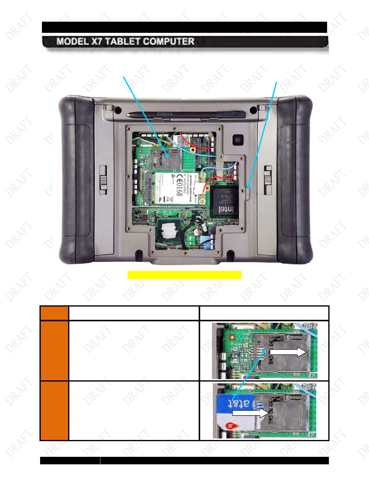
SECTION 7 MAINTAINING YOUR ARMOR X7 PAGE 153
9711-26400-0001
EXPORT CONTROLLED – SEE PAGE 3
Rev -
Figure 75. X7 Rear Compartment
STEP ACTION CONDITION OR INDICATION
6.
Place a fingertip in the notch
on the left
side of the SIM socket cover and slide the
cover to the right until you feel an indent,
then lift up.
7.
Insert the SIM card with the corner notch
at the lower left.
SIM CARD
SOCKET
COVER
REMOVAL
SLOT
NOTCH
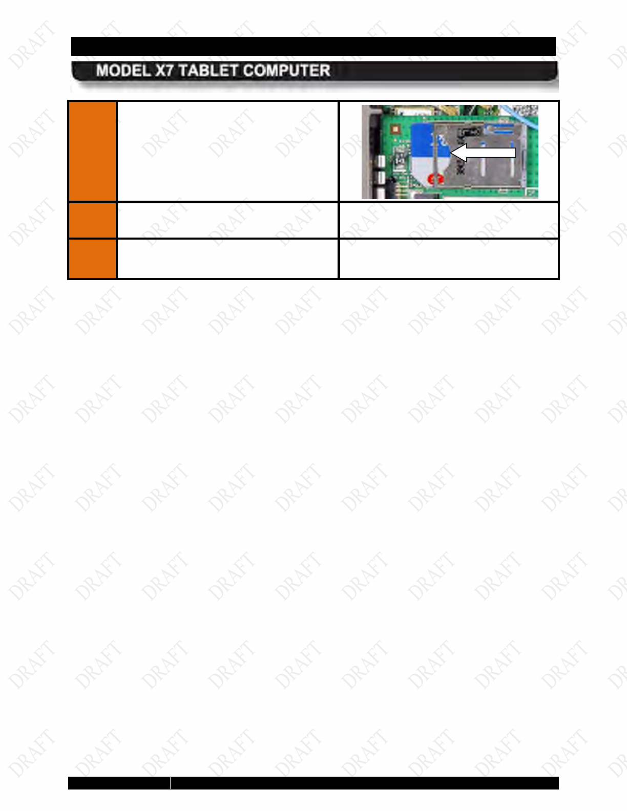
SECTION 7 MAINTAINING YOUR ARMOR X7 PAGE 154
9711-26400-0001
EXPORT CONTROLLED – SEE PAGE 3
Rev -
8.
Gently press the cover down and slide to
the left to lock in place.
9.
Reinstall the cooling register and secure
with the 14 Philips screws.
10.
Torque each screw to 2.8 kg-cm (2.4 in-
lb).
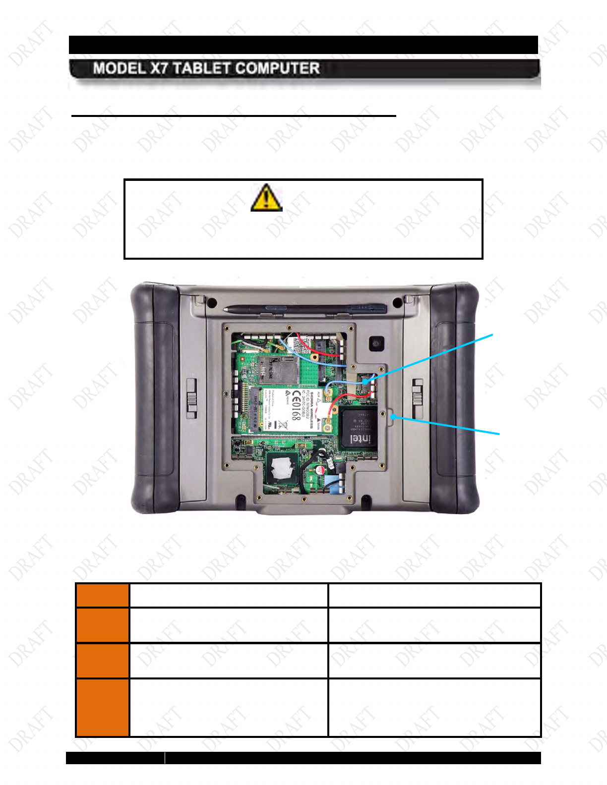
SECTION 7 MAINTAINING YOUR ARMOR X7 PAGE 155
9711-26400-0001
EXPORT CONTROLLED – SEE PAGE 3
Rev -
The micro SD card socket is located inside the rear compartment, as shown in
Installing a Micro SD or SDHC Card
Figure 76. Follow
the procedure in Table 24 to install the card.
CAUTION!
Do not remove the rear compartment cover while the unit is
powered up as internal voltages are exposed to possible short
circuit.
Figure 76. Micro SD Card Socket
Table 24. Installing the SC Card
STEP ACTION CONDITION OR INDICATION
1.
Power down the computer and
disconnect any external power.
2.
Remove the batteries.
3.
Place the computer face down on a
clean surface and remove the 14
Philips screws
securing the cooling
register.
MICRO SD
CARD
SOCKET
COVER
REMOVAL
SLOT
SECTION 7 MAINTAINING YOUR ARMOR X7 PAGE 156
9711-26400-0001
EXPORT CONTROLLED – SEE PAGE 3
Rev -
STEP ACTION CONDITION OR INDICATION
4.
Carefully pry up the cooling
register/cover
at the slot provided
(Figure 76) and remove.
5.
Carefully lift the socket cover and
insert the SD card all the way into the
cover.
6.
Press the card down until it locks in
place.
7.
Replace the cooling register/cover and
secure with 14 Philips screws.
8.
Reinstall the batteries and re-connect
external power if desired.
SECTION 7 MAINTAINING YOUR ARMOR X7 PAGE 157
9711-26400-0001
EXPORT CONTROLLED – SEE PAGE 3
Rev -
Follow the procedure in
Changing the BIOS Settings
Table 25 to access the BIOS setup utility and verify settings or make
changes. You can use the active pen (not a stylus or fingertip) to navigate the setup screens
and select options, or you can connect an external keyboard to one of the USB ports.
Contact DRS Technical Support
if you have any questions about the BIOS settings for your
ARMOR X7.
CAUTION!
Incorrectly setting the BIOS options could cause the X7 to become
unstable or render it completely inoperable. Move carefully through
the menus and use caution when making changes. Read the
description of each change in the right-hand column before making
any adjustments.
NOTE
If you make permanent changes as a result of an upgrade or
addition of new
equipment, be sure to keep a record of the
changes. Table 26 provides a handy place to record these changes.
Always record the previous value in case you have to return to that
value.
Table 25. Access the BIOS Setup Utility.
STEP ACTION
1.
You can use the active pen to navigate in the BIOS setup screens or you can attach a
USB keyboard to the USB port on the right side of the computer.
2.
Start the computer and as soon as the DRS logo appears, tap on the screen until you
hear a beep. A small options menu will be displayed.
3.
Select Launch System Setup to open the Setup Utility main screen.
4.
Use the LEFT and RIGHT ARROW keys to highlight the desired menu page (listed at
the top of the screen) and press ENTER to select the menu.
5.
Use the UP and DOWN ARROW
keys to scroll through the page settings and to
highlight a particular setting or sub-option.
SECTION 7 MAINTAINING YOUR ARMOR X7 PAGE 158
9711-26400-0001
EXPORT CONTROLLED – SEE PAGE 3
Rev -
6.
Select ENTER to access the sub-options under a highlighted option. Press ESC to
return to the previous option or menu.
7.
Use the F5 and F6
keys to cycle through the available options and highlight the
desired value to change.
8.
Select ESC to exit the option.
9.
Use the arrow keys to move to the next option.
10.
When all changes have been made, select F10 to exit and save your changes or
select ESC to exit without saving any changes. The computer will resume booting.
Table 26. Record Bios Changes Here
SETTING PREVIOUS
VALUE NEW
VALUE
DATE
CHANGED
SECTION 7 MAINTAINING YOUR ARMOR X7 PAGE 159
9711-26400-0001
EXPORT CONTROLLED – SEE PAGE 3
Rev -
When your X10gx was shipped to you, the BIOS settings were set to a “default” state for your
particular configuration. Follow the procedure in
Returning the BIOS to its Default Settings
Table 27 to return the BIOS to it’s default state.
NOTE
Defaulting the BIOS will change the brightness control to the
“Automatic” adjustment mode. To change the adjustment to
manual, open the Backlight Setup in ARMORutils and select Manual
mode.
Table 27. Return the BIOS to Its Default State
STEP ACTION CONDITION OR INDICATION
1.
Access the BIOS Setup Utility (see
Error! Reference source not found. for
instructions).
2.
Press F9
to load the default BIOS
configuration.
3.
Press F10
to save your changes and
exit.
SECTION 7 MAINTAINING YOUR ARMOR X7 PAGE 160
9711-26400-0001
EXPORT CONTROLLED – SEE PAGE 3
Rev -
Follow the procedure in
Changing the Power Button Default Action
Table 28 to change the default actions of the Power button.
Table 28. Changing the Power Button Default Actions
STEP ACTION CONDITION OR INDICATION
1.
Select Start
à
Control Panel
à
Hardware & Sound
à
Power Options
The Power Options dialog window is
displayed.
2.
From the left panel, select Choose what
the power buttons do.
The Systems Settings window opens as
shown in Figure 77.
NOTE
The X10gx does not have a Sleep
button so ignore the bottom set
of options.
3.
Click on the pull-down menus in the On
battery and Plugged in
columns and
select the desired action.
The pull-down menu options are shown in
Figure 77.
4.
Click on the Save Changes
button at
the bottom of the window.
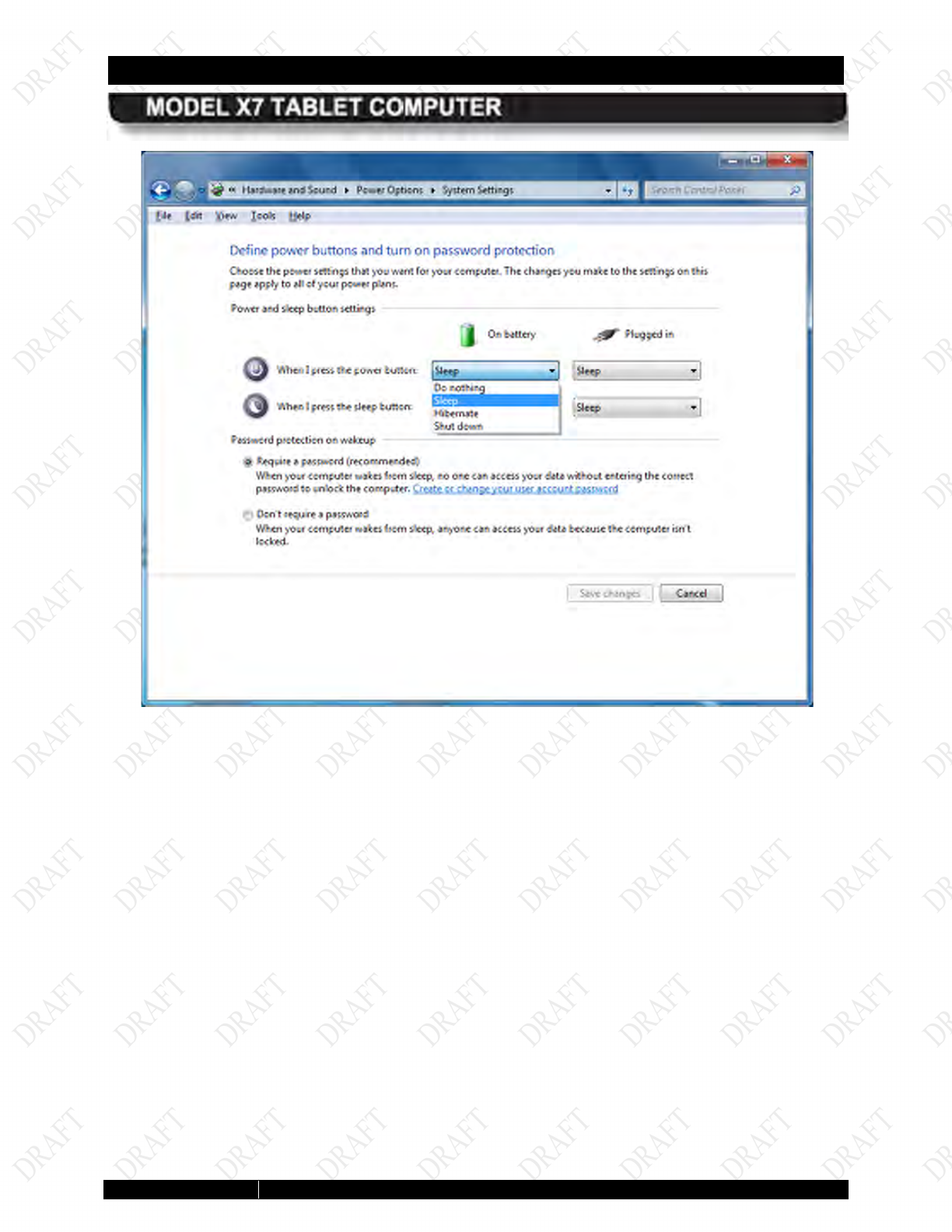
SECTION 7 MAINTAINING YOUR ARMOR X7 PAGE 161
9711-26400-0001
EXPORT CONTROLLED – SEE PAGE 3
Rev -
Figure 77. Power Button Settings Options
SECTION 7 MAINTAINING YOUR ARMOR X7 PAGE 162
9711-26400-0001
EXPORT CONTROLLED – SEE PAGE 3
Rev -
The following tips will help you keep your display clean and healthy:
Caring For the Display Screen
CAUTION!
Use only canned compressed air to clean your screen. Do not use
an air compressor. Damage to the screen surface could result.
CAUTION!
Do not
attempt to remove stuck particles with a fingernail or other
hard object as this can permanently damage the touch screen
surface.
• Do not use an abrasive or metallic pointer on the screen surface as this may damage the
screen. Use the pen included with your X7, a passive stylus designed for touch screens
(not included) or your fingertip.
• Use a plastic cleaner such as Plexus™ to clean the pen tip.
• Be careful not to let sand or grit stay on the screen as this can scratch the surface when
wiped with a cloth. Clean the display surface first with canned dry compressed air (do
not exceed 60psi pressure) or a soft bristle brush.
• Use the special ARMOR cloth that came with your X10gx to wipe away dust and
fingerprints.
• For stubborn residue, clean the surface with plain water or water with a few drops of dish
soap added and pat dry with a clean paper towel or cloth, then use the special ARMOR
cloth that came with your tablet to remove any remaining residue.
• Use a cotton swab with plain water, soapy water, alcohol or glass cleaner to gently
remove particles stuck to the surface.
SECTION 7 MAINTAINING YOUR ARMOR X7 PAGE 163
9711-26400-0001
EXPORT CONTROLLED – SEE PAGE 3
Rev -
If you are experiencing problems and suspect that they are temperature related, you can
monitor the internal temperature of the X7 by clicking on Start à All Programs à ARMORutils
or double-clicking on the ARMORutils icon on the desktop to open the ARMORutils Diagnostics
dialog window (see
Monitoring the Health of Your ARMOR X7
Figure 78). The window displays the following internal temperatures of the
X7 tablet:
• CPU core temperature (DTS and Diode)
• CPU Main Board temperature
• Battery #1 temperature
• Battery #2 temperature
The CPU temperatures vary widely depending on the operation of the tablet and may not
necessarily correlate with outside (ambient) temperatures.
If you suspect a temperature related problem, please contact Error! Reference source not
found. for assistance in troubleshooting and resolving the problem.
NOTE
The indicated temperatures for the CPU and mainboard can
indicate up to 35°C higher than the ambient temperature of the
tablet.
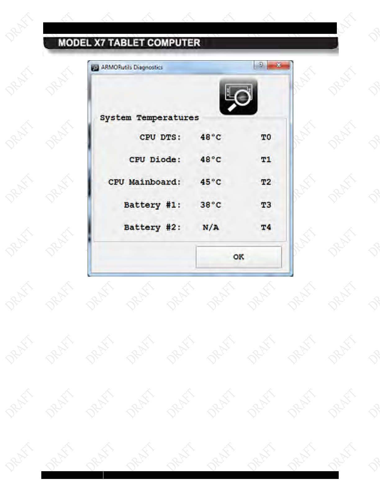
SECTION 7 MAINTAINING YOUR ARMOR X7 PAGE 164
9711-26400-0001
EXPORT CONTROLLED – SEE PAGE 3
Rev -
Figure 78. ARMORutils Diagnostics Dialog Window
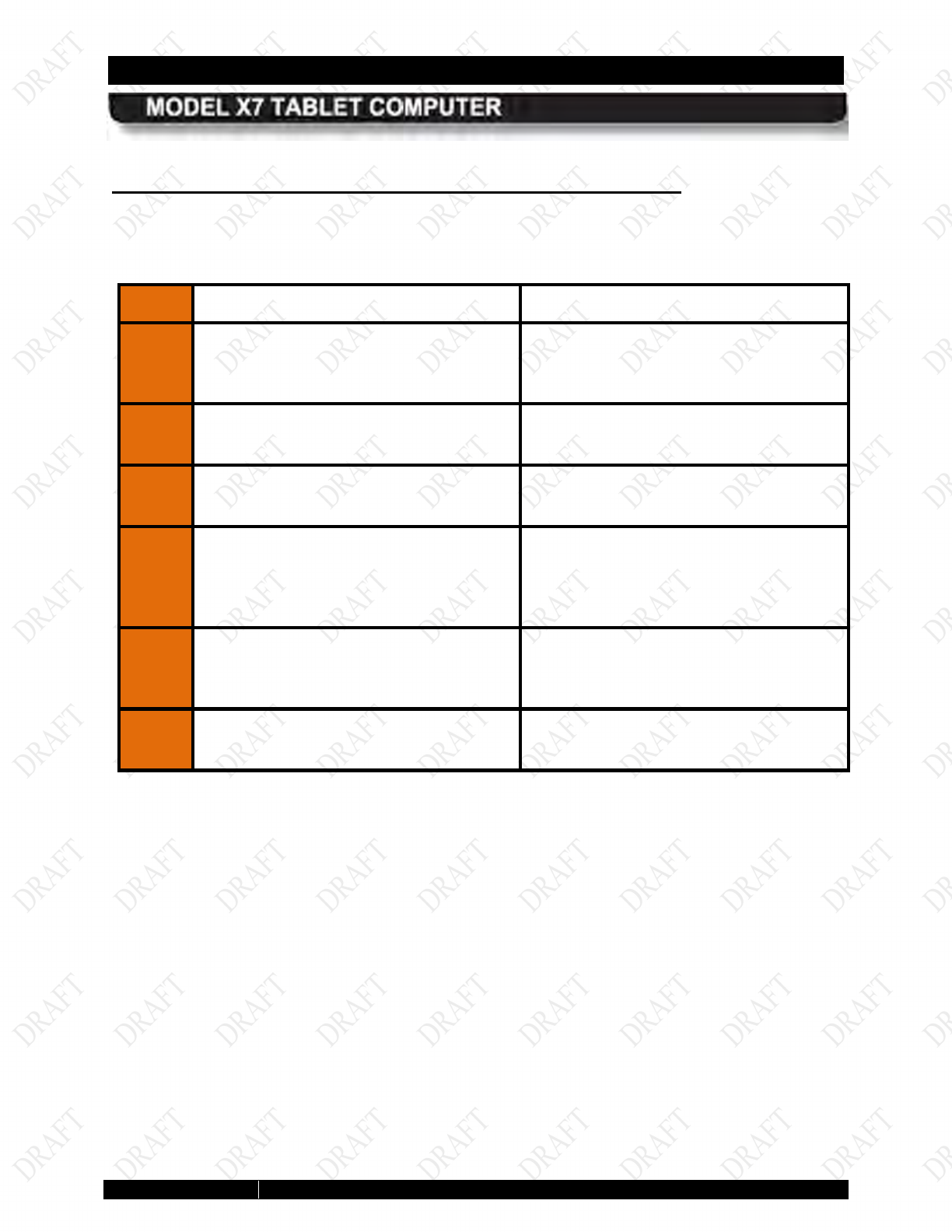
SECTION 7 MAINTAINING YOUR ARMOR X7 PAGE 165
9711-26400-0001
EXPORT CONTROLLED – SEE PAGE 3
Rev -
If a problem is occurring over time, you can record system temperature variations over time by
creating a temperature variation log file. Follow the procedure in
Generating a Log of Temperature Variations
Table 29 to set up the log file.
Table 29. Generate a Temperature Variation Log
STEP ACTION CONDITION OR INDICATION
1.
Select START à All PROGRAMS
à
ARMORutils and select the
Diagnostics page.
The page opens as shown in Figure 78.
2.
Click on the Event Recording button. The Event Recording window opens as
shown in Figure 79.
3.
Enter a name for the log file in the File
Name field.
The name should be in the format
xxxxx.txt
4.
In the Path
field, enter the path to the
folder where you want the log file to
reside or click on the Set Path button
and select the folder.
5.
Select START TEMPERATURE LOG to
begin generating a record of
temperature changes over time.
6.
Select the STOP TEMPERATURE LOG
option to stop recording temperatures. A sample log file is shown in Figure 80.
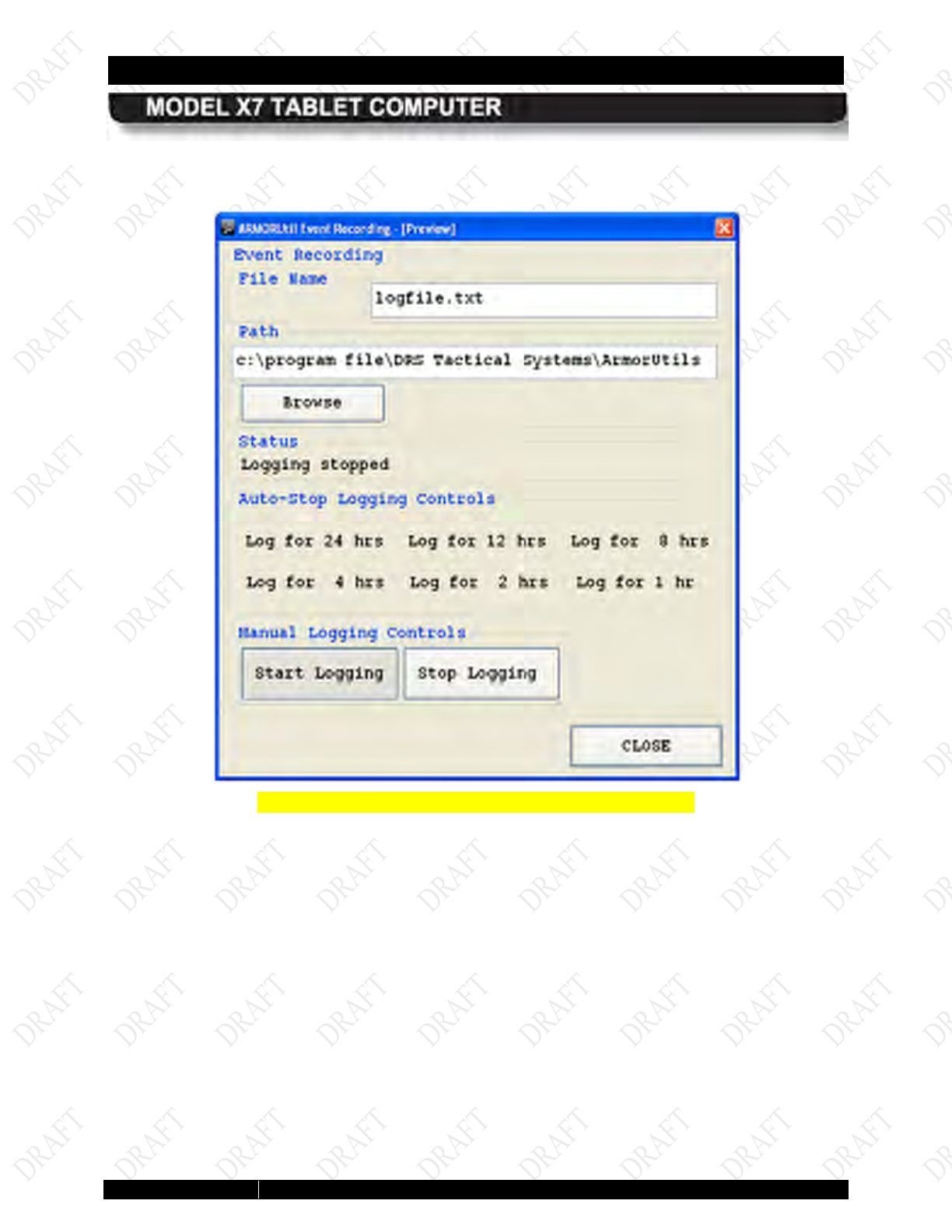
SECTION 7 MAINTAINING YOUR ARMOR X7 PAGE 166
9711-26400-0001
EXPORT CONTROLLED – SEE PAGE 3
Rev -
Figure 79. ARMORutils Event Recording Window
[Update image to Win 7]
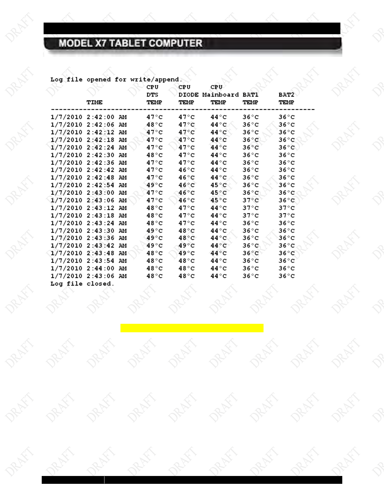
SECTION 7 MAINTAINING YOUR ARMOR X7 PAGE 167
9711-26400-0001
EXPORT CONTROLLED – SEE PAGE 3
Rev -
Figure 80. Sample Temperature Log File
[“Core X” column headers do not correspond to Diagnostics dialog window titles (T0, T1,
T2….)
“System Temp” column header is “Core T2” in the Diagnostics dialog window titles]
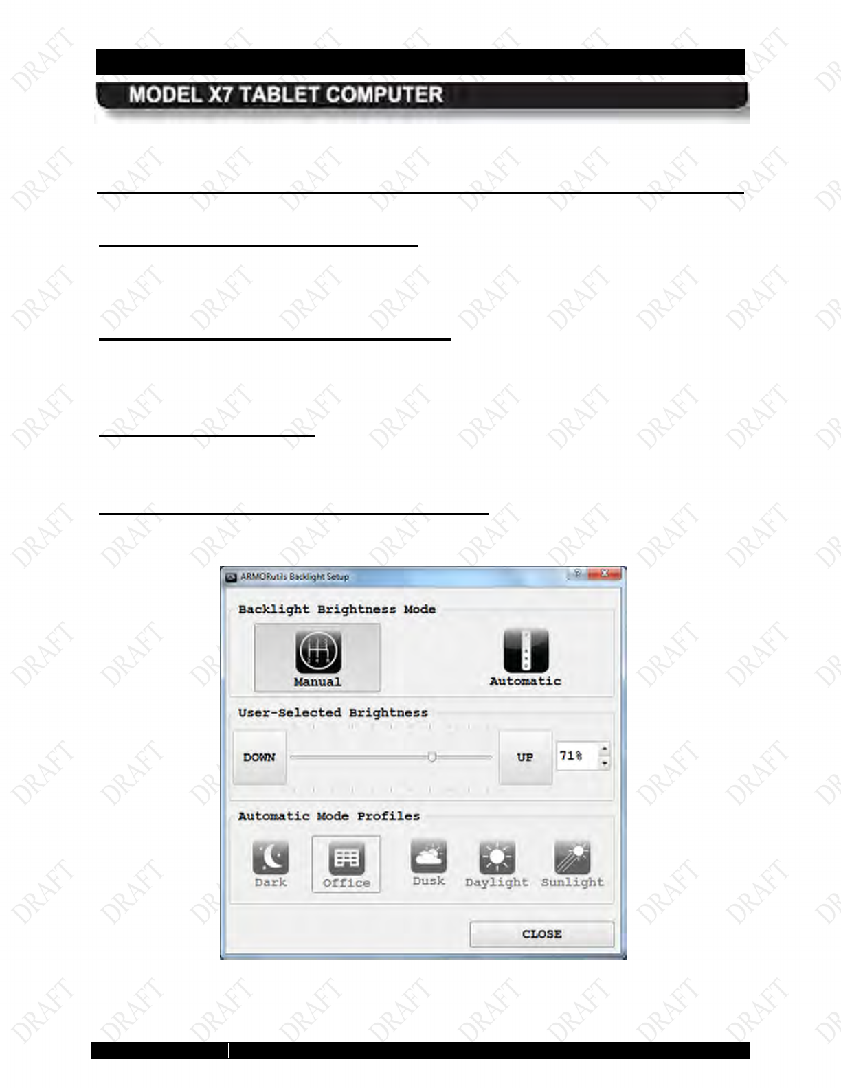
SECTION 8 DISPLAY MANAGEMENT PAGE 168
9711-26400-0001
EXPORT CONTROLLED – SEE PAGE 3
Rev -
8. DISPLAY MANAGEMENT
The brightness of an LCD display is controlled by adjusting the intensity of the backlight. The
backlight level for the X7 can be controlled manually or automatically.
Adjusting the Brightness
Your ARMOR X7 computer is pre-set for manual adjustment of screen brightness. The backlight
level can be adjusted manually in two ways: by pressing a button sequence on the control panel
or by adjusting the slider in the Backlight Setup dialog window of ARMORutils.
Manual Brightness Adjustment
Press the Fn button once (do not hold) and then repeatedly press the P1 button. The brightness
will increase in steps until it reaches 100%, then will start over at minimum brightness.
Using a Button Sequence
Double-click on the ARMORutils desktop icon and select the Backlight Setup button. The
Backlight Setup dialog opens as shown in
Using the ARMORutils Backlight Setup Dialog
Error! Reference source not found..
Figure 81. Armor Utilities Screen – Backlight Tab
SECTION 8 DISPLAY MANAGEMENT PAGE 169
9711-26400-0001
EXPORT CONTROLLED – SEE PAGE 3
Rev -
Press the UP or DOWN buttons repeatedly with the pen or a fingertip to move the slider and
adjust the backlight level. The % brightness is displayed in a field on the right. You can also use
the stylus with the up and down arrows next to this field to adjust the slider.
Open the Backlight Setup dialog in ARMORutils and click on the Automatic button. The
backlight level will now be controlled by the light sensor. If the surrounding light decreases, the
brightness will also decreases proportionally; if the surrounding light increases, the brightness
will increase.
Automatic Adjustment
NOTE
You must
keep the light sensor uncovered to allow proper
automatic brightness adjustment.
Select one of the profiles that best controls the range of backlight levels to suit your work
environment.
Automatic Mode Profiles
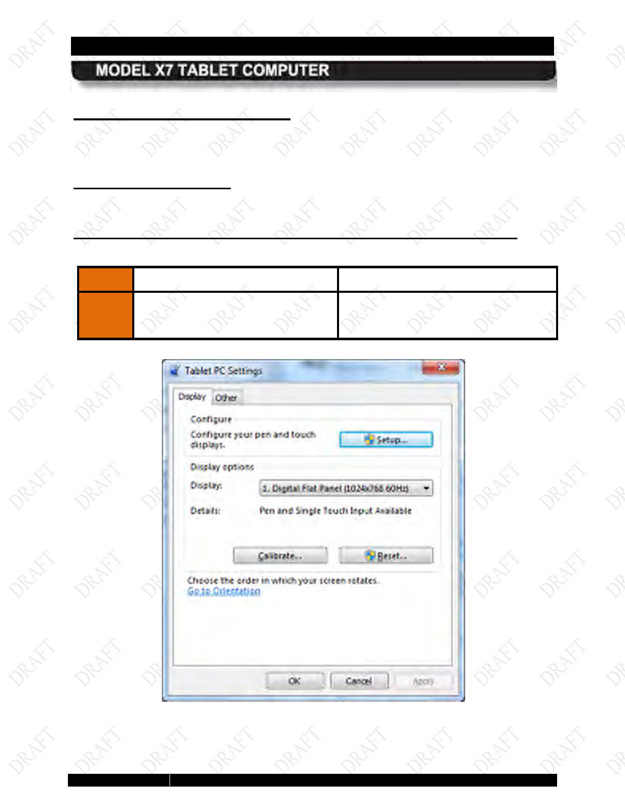
SECTION 8 DISPLAY MANAGEMENT PAGE 170
9711-26400-0001
EXPORT CONTROLLED – SEE PAGE 3
Rev -
You can access both touch screen and pen screen calibration routines using ARMORutils or
using the Tablet PC Settings utility in Control Panel.
Calibrating the Display
Open ARMORutils and click on the Screen Settings button.
Us ing ARMORutils
Table 30. Calibrate the Display Using the Tablet PC Settings Utility
Using the Tablet PC Settings Utility in Control Panel
STEP ACTION CONDITION OR INDICATION
1. Select Start
à
Control Panel
à
Hardware and Sound
à
Tablet PC
Settings.
The Tablet PC Settings dialog window
opens, as shown in Figure 82.
Figure 82. Tablet PC Settings Window
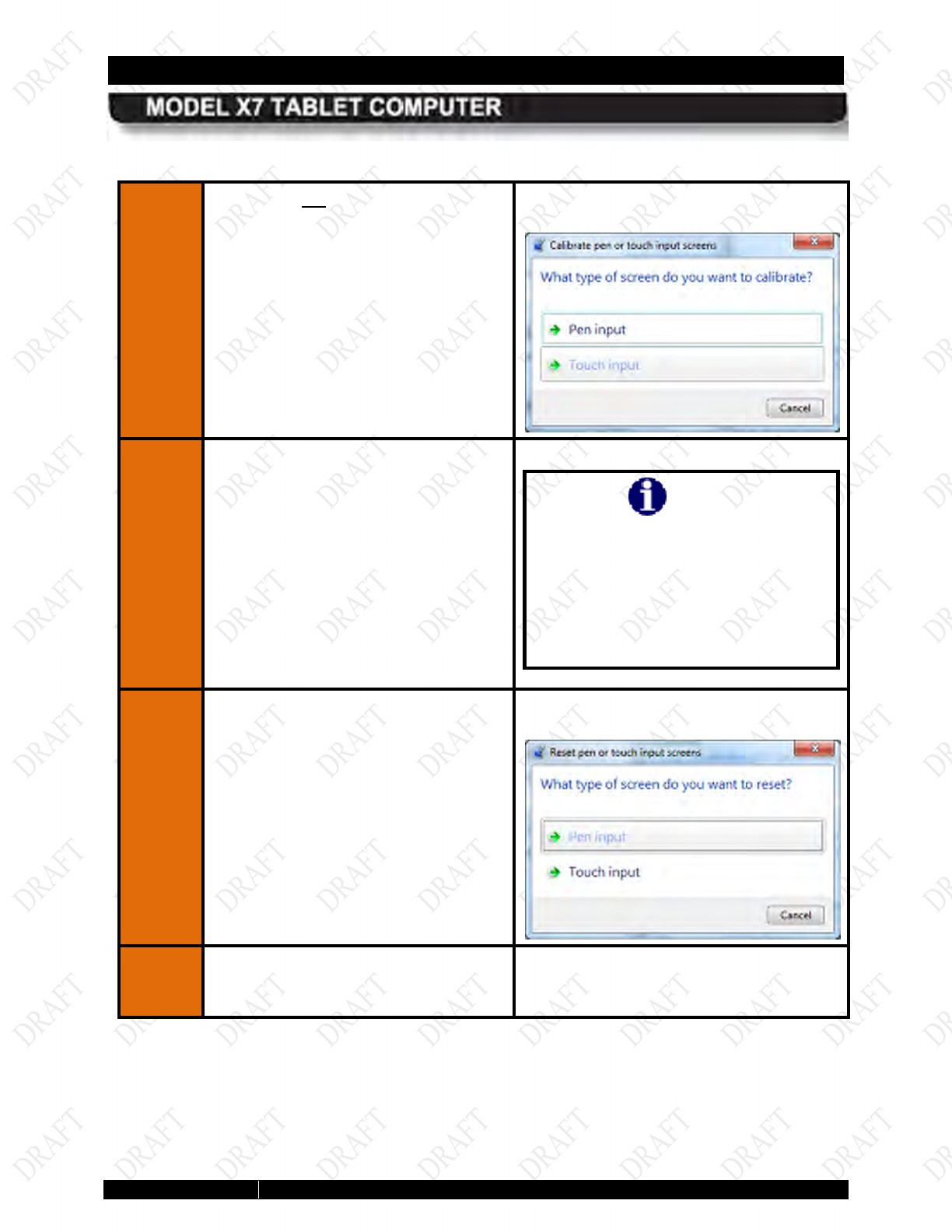
SECTION 8 DISPLAY MANAGEMENT PAGE 171
9711-26400-0001
EXPORT CONTROLLED – SEE PAGE 3
Rev -
2. If you are not
Otherwise, go to Step 4.
having problems with
screen calibration and want to do a
quick 4-
point calibration, click on the
Calibrate button.
The
Calibrate Pen or Touch Input
Screens window opens, as shown below:
3. Choose the type of screen to calibrate
and follow the on-screen instructions.
NOTE
If you do not have an external
keyboard
connected, you can
invoke the ESC command using the
Input Panel virtual keyboard. Hover
with the pen or tap on the screen in
the upper left corner near the left
edge. The keyboard will appear.
4.
If you are having screen calibration
problems or want to do a precision 16-
point calibration, click on the Reset
button
The Reset Pen or Touch Input Screens
window opens, as shown below:
5. Select the screen calibration you want
to reset. The current screen calibration points are
reset to their default values and the
selection screen closes.
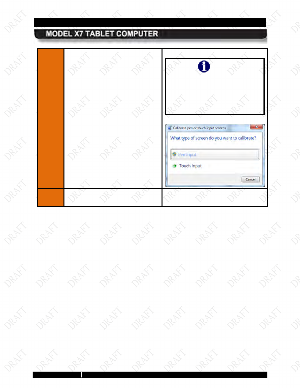
SECTION 8 DISPLAY MANAGEMENT PAGE 172
9711-26400-0001
EXPORT CONTROLLED – SEE PAGE 3
Rev -
6. Click on Calibrate
and select the
screen you want to calibrate.
NOTE
A shield symbol next to the screen
type (shown below
next to Pen
input) indicates the calibration data
has been reset and is not calibrated;
a green arrow indicates that the
screen is calibrated.
7. Follow the on-screen instructions.
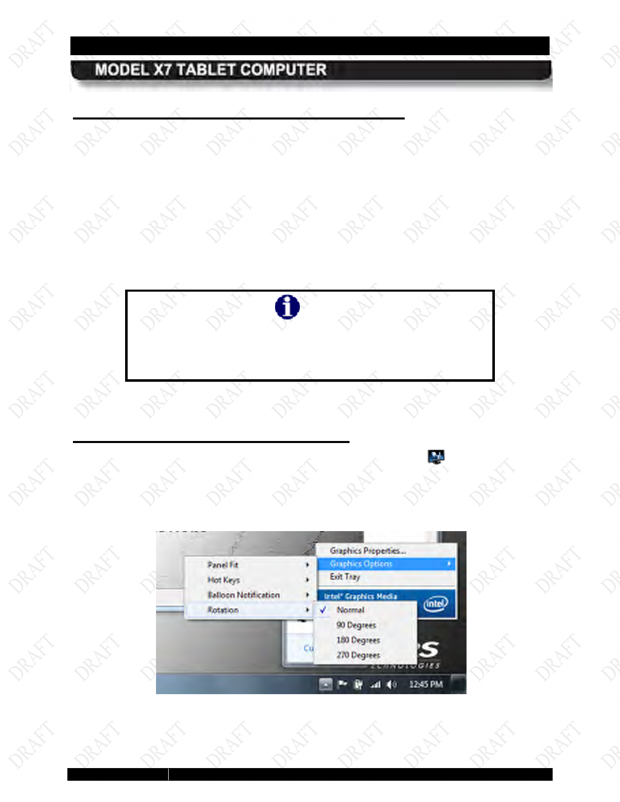
SECTION 8 DISPLAY MANAGEMENT PAGE 173
9711-26400-0001
EXPORT CONTROLLED – SEE PAGE 3
Rev -
Your ARMOR X7 supports the Windows function of rotating the screen between Landscape and
Portrait layout mode. In landscape mode (default orientation), the long axis of the screen is
along the top and bottom of the display. In portrait mode, you turn the computer 90° and the
long axis of the screen is along the left and right sides of the display.
Rotating the Screen (Touch or Pen)
There are three ways to rotate the screen:
• By using the Intel Graphics options via the desktop or icon tray
• By using the Intel Graphics and Media Control panel
• By using a hot key combination with an external keyboard
NOTE
If you lose calibration when rotating the screen and cannot use the
pen to return to the default orientation, attach an external keyboard
and press Ctrl+Alt+Up Arrow. This will return the display to the
default landscape orientation.
Right click anywhere on the desktop or click on the Intel Graphics icon in the icon tray (you
may have to show hidden icons) and select Graphics Options à Rotation. Then select one of
the four rotation angles as shown in
Us ing the Intel Graphics Options
Figure 83. NOTE: The “Normal” position is the default
landscape orientation as shown in Error! Reference source not found..
Figure 83. Intel Graphics Screen Rotation Options (from icon tray)
You can rotate the screen clockwise in four 90 degree steps, alternating between portrait and
landscape orientation, or you can rotate it 180° or 270°.
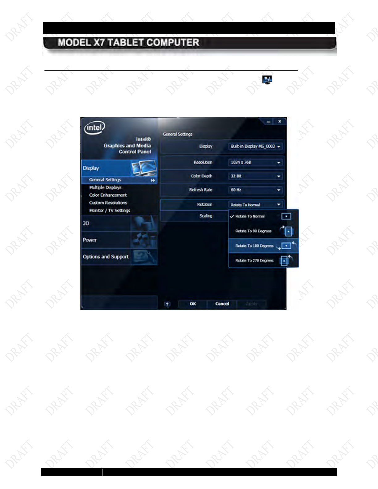
SECTION 8 DISPLAY MANAGEMENT PAGE 174
9711-26400-0001
EXPORT CONTROLLED – SEE PAGE 3
Rev -
Right-click anywhere on the desktop or click on the Intel Graphics icon in the icon tray and
select Graphics Properties to open the Intel Graphics and Media Control Panel, as shown in
Us ing the Intel Graphics and Media Control Panel
Figure 84. Select the rotation angle and click OK.
Figure 84. Intel Graphics and Media Control Panel
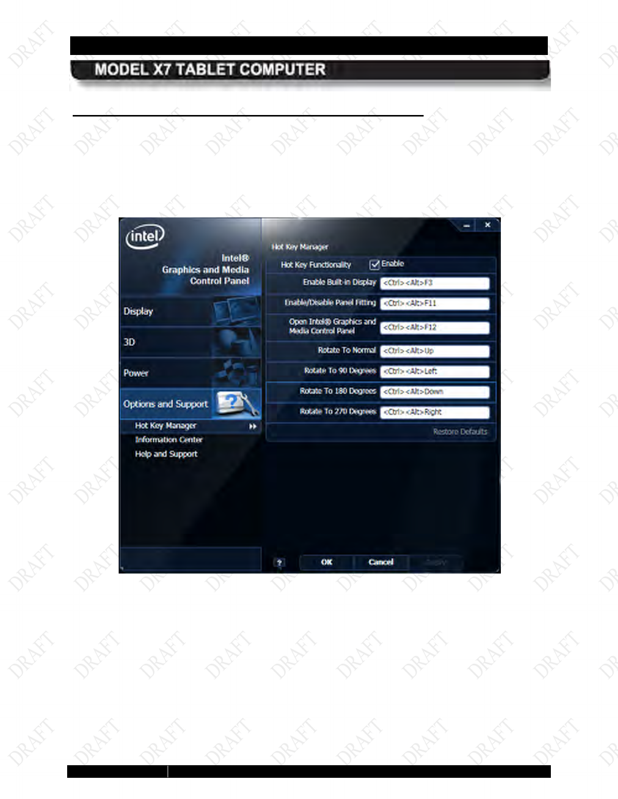
SECTION 8 DISPLAY MANAGEMENT PAGE 175
9711-26400-0001
EXPORT CONTROLLED – SEE PAGE 3
Rev -
Open the Intel Graphics and Media Control Panel and select Options and Support à Hot Key
Manager. A list of pre-assigned (default) hot key combinations is displayed in the right panel, as
shown in
Us ing a Keyboard “Hot Key” Combination
Figure 85. You can use these default combinations or specify a combination of your
own.
To use a hot key combination, connect a USB keyboard and enter the combination.
Figure 85. Intel Graphics Panel Hot Key Manager

SECTION 8 DISPLAY MANAGEMENT PAGE 176
9711-26400-0001
EXPORT CONTROLLED – SEE PAGE 3
Rev -
This Page Intentionally Left Blank
SECTION 9 BATTERY MANAGEMENT PAGE 177
9711-26400-0001
EXPORT CONTROLLED – SEE PAGE 3
Rev -
9. BATTERY MANAGEMENT
The Lithium Ion batteries used in your ARMOR X7 computer offer the best technology available
today. These ‘Smart Batteries’ provide ARMOR X7 users with the greatest power density and
the most accurate “fuel gauge” possible. To achieve the best possible performance from your
batteries, we recommend using and maintaining the batteries in accordance with the
instructions provided in this section.
WARNING!
Do not drop or mishandle the batteries, immerse them in water, or
subject them to high heat. Doing so could increase the risk of
explosion or leakage, and possibly cause injury.
WARNING!
The lithium-ion batteries used in
this equipment contain material
that is hazardous to your health. If battery contents come in contact
with the eyes, IMMEDIATELY flush the affected area with clean
water for 15 minutes and have someone else summon medical
attention for you. Unaffected per
sons should assist the affected
individual in the vital first flushing of the eyes.
WARNING!
If battery material comes in contact with the skin, flush the affected
area with clean water and seek immediate medical treatment.
SECTION 9 BATTERY MANAGEMENT PAGE 178
9711-26400-0001
EXPORT CONTROLLED – SEE PAGE 3
Rev -
Please use the following safety rules when handling and using lithium-Ion batteries.
Safety and Handling Considerations for Your
Batteries
• Do not expose the batteries to very high temperatures such as an open flame.
• Do not short circuit the battery contacts or reverse their polarity.
• Do not let children play with the batteries.
• Do not crush, dent or allow any deformation of the batteries.
• Do not disassemble or open the batteries or try to alter or bypass the internal safety
circuits.
• Avoid exposing the batteries to wet or extremely humid conditions.
• Avoid exposing the batteries to electrostatic discharge.
• Avoid dropping the batteries.
• Do not use in, or connect the batteries to, any other devices.
• Do not allow batteries to remain discharged for more than 1 week
When to Charge a Battery
Due to current regulations regarding shipment of lithium Ion batteries, your X7 batteries are
shipped to you in a partially charged condition, typically with a maximum charge of 30%-50%.
DRS recommends that you fully charge your batteries before using the computer on batteries
alone.
Initial Us e and Newly Received Batteries
If you do not plan to use your computer immediately, be aware that the batteries will discharge
as much as 4% in 24 hours if left in the computer with the power turned off. For this reason, we
recommend that computers with the batteries left in that will not be used for an extended period
of time be connected to external power, either using the AC adapter provided with your
computer, or an external battery charger or through a vehicle power supply.
CAUTION!
X7 batteries should not be left installed in a computer that is
connected to external power and left in a high-temperature
environment, such as in a hot vehicle cab, for
more than 30
minutes at a time. Prolonged exposure to high heat with external
power applied can cause loss of capacity and reduced battery life.
SECTION 9 BATTERY MANAGEMENT PAGE 179
9711-26400-0001
EXPORT CONTROLLED – SEE PAGE 3
Rev -
To check the remaining charge of a battery that is disconnected from the computer, press the
fuel gauge button to activate the fuel gauge (see
Removed Batteries
Figure 19). The lowest indicator will flash when
the battery is at 10% charge or below. Because batteries will continue to self-discharge slightly
even when disconnected, DRS recommends you recharge your batteries as soon as possible
after they reach the 10% level (LED #1 flashing).
When an installed battery’s charge drops below 10%, a warning message, similar to the one in
In s ta lle d Batteries
Figure 86 will appear on the screen. At this point, the battery is in a depleted charge state
(between 10% and 3%). If the total charge drops below 5%, the computer will enter the
hibernate state, where your Windows session is automatically saved to the hard drive and the
computer is shut down to save power.
NOTE
It is possible that high current demand on the batteries could cause
the remaining charge to drop too rapidly for the hibernate process to
take place, resulting in the computer shutting down unexpectedly.
To avoid having your computer enter the hibernate mode or possibly
shut down suddenly with the
loss of your current session, you
should connect external power to recharge your batteries as soon as
you see the warning message, or replace them immediately with
fresh batteries..
SECTION 9 BATTERY MANAGEMENT PAGE 180
9711-26400-0001
EXPORT CONTROLLED – SEE PAGE 3
Rev -
A battery is considered depleted when its charge falls below 10%. If left in a computer even
with power off, a battery will still discharge 3-4% over a 24 hour period. If a battery’s charge is
allowed to drop below the 3% level (fully depleted), an internal safety circuit could activate and
render the battery un-rechargeable. Remove a depleted battery as soon as possible or connect
external power to recharge it.
Depleted Batteries
A lithium battery that is not installed in the X7 will self discharge at the rate of about 0.3% per
day or 3% every 10 days (faster in higher temperature conditions). A depleted battery that is
removed is therefore in danger of becoming fully depleted after about 23 days.
To protect the life of your batteries, DRS recommends you wait no longer than 10 days to
recharge a depleted battery.
CAUTION!
Batteries that are allowed to discharge below the 3% charge level
may not be recoverable and may have to be discarded.
How to Charge Your Batteries
The X7 batteries automatically begin charging when installed in the computer and external
power is applied.
Using the X7 Computer
To recharge the batteries using the computer, plug the circular connector of the AC adapter into
the DC input jack on the left side of the ARMOR X7, or into the PWR connector on a desk dock
unit. If your X7 is installed in a vehicle dock, the batteries will charge whenever vehicle battery
power is available.
Don’t be alarmed if batteries feel warm to the touch during the charging process.
The X7 external battery charger will charge a single battery in about 2.5 hours, or two batteries
in about 4.5 hours. For instructions on using the external battery charger, see Appendix B,
Using the Optional X7 External Battery Charger
Using the X7 External Battery Charger
The charging time for one or two fully depleted battery (10% charge or less) will depend
primarily on the following:
Charging Times
• power demands on the system (screen brightness setting, wireless and GPS radio
activity, utility and software applications currently running, etc.)
• temperature extremes
• number of batteries (1 or 2)
• total capacity of each battery
Two types of batteries are available for the X7: a 2-cell type with 2850 mAh capacity and a 4-
cell type with 5900 mAh capacity. Table 31 lists typical charging times for each battery type.
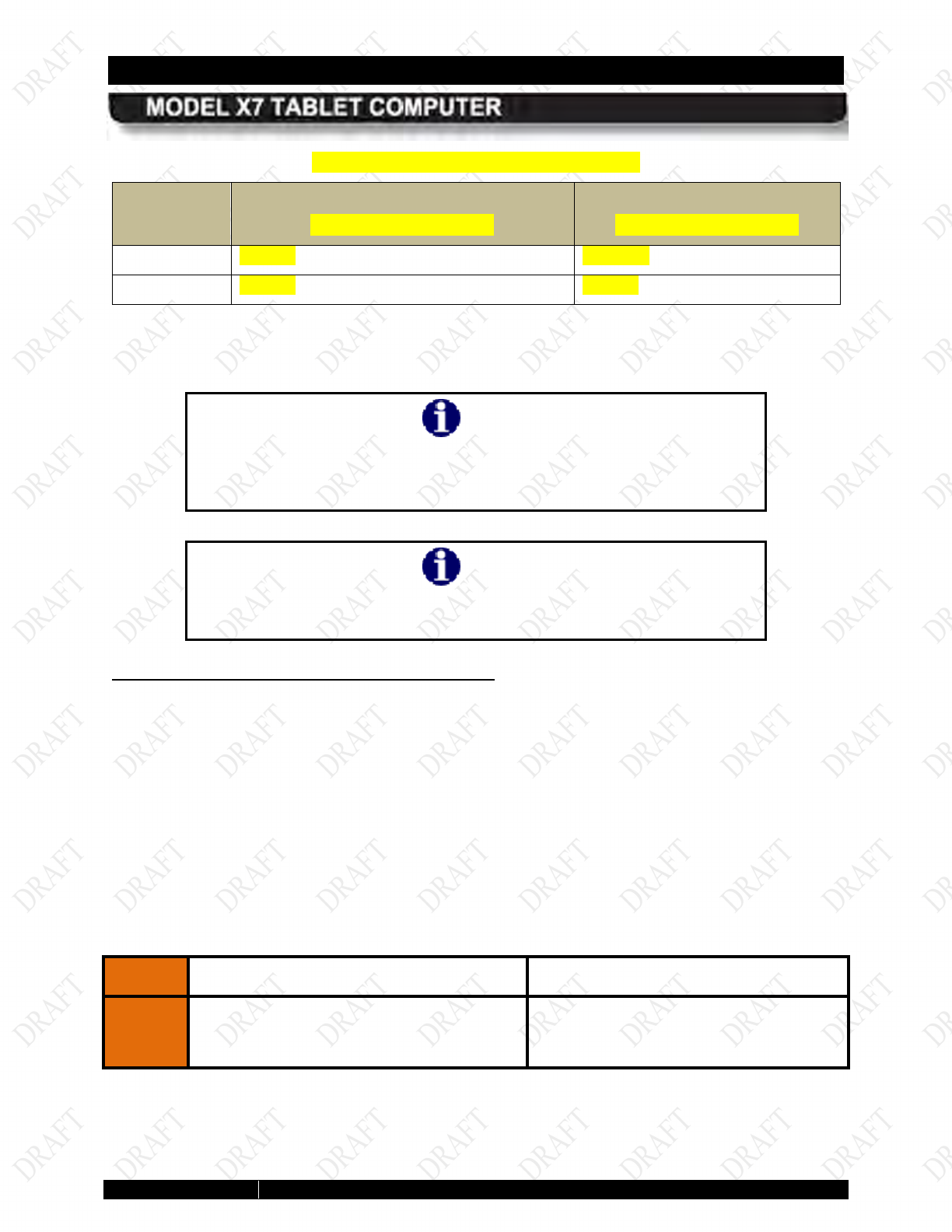
SECTION 9 BATTERY MANAGEMENT PAGE 181
9711-26400-0001
EXPORT CONTROLLED – SEE PAGE 3
Rev -
Table 31. X7 Battery Charging Times
Number of
Batteries
2-Cell Battery
P/N xxxx-xxxxx-xxxx
4-Cell Battery
P/N xxxx-xxxxx-xxxx
2
x hours
8+ hours
1
x hours
x hours
NOTE
If the internal battery temperature exceeds 45°C during charging, the
computer will suspend the charging cycle until the temperature
drops back into the normal operating range.
NOTE
The charging cycle is not linear and the last 20% of charge takes
proportionally longer to complete than the first 80% of charge time.
If you have two batteries installed, you can select if both will charge at the same time
(simultaneous mode) or if the battery with the lowest charge will charge first (sequential mode).
The default mode is simultaneous.
Selecting How to Charge Your Batteries
In simultaneous mode, both batteries will charge at the same time regardless of individual
battery charge level.
If you choose sequential mode, the battery with the lowest charge will be charged to 80%,
followed by the next lowest battery. Once both are at 80%, the first charged battery will be
charged to 100%, followed by the second charged battery.
Follow the procedure in Table 32 to select if your batteries will charge simultaneously or
sequentially.
Table 32. Select How to Charge the Batteries
STEP ACTION CONDITION OR INDICATION
1. Connect external power.
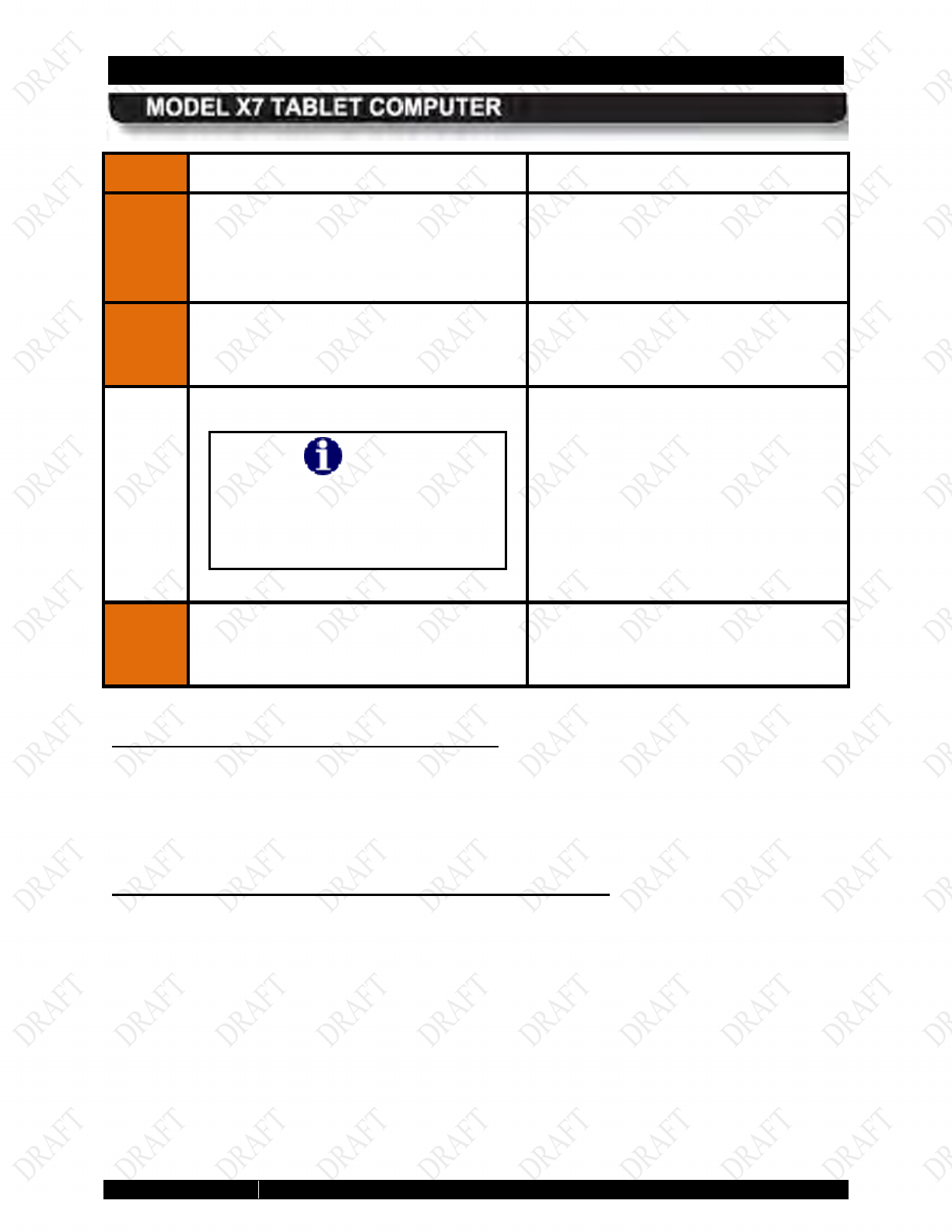
SECTION 9 BATTERY MANAGEMENT PAGE 182
9711-26400-0001
EXPORT CONTROLLED – SEE PAGE 3
Rev -
STEP ACTION CONDITION OR INDICATION
2. Double-click on the ARMORutils icon on
the desktop and select the Battery
Monitor
dialog page from the Main
screen.
The Battery Monitor dialog page opens.
3. Click on the Charger Settings button.
The Charger Control Settings window
opens.
NOTE
If total system current exceeds 4
amps while charging two
batteries, the charger will switch
to sequential battery charging.
4. Select Charge Both
(simultaneous) or
Charge Lowest First (sequential).
DRS has included temperature sensors in the battery circuit to protect the cells when a high or
low temperature condition occurs. Recharging a battery under extreme temperature conditions
can force the charger to suspend charging until the temperature returns to a safe level. This can
occur if the internal temperature of the battery falls below -10°C (14°F) or exceeds 45°C
(113°F).
Temperature Can Affect Charging Times
While the batteries are charging, the fuel gauge LEDs will light to indicate the current level of
charge and the amber battery status LED will be on steady. When the batteries are fully
charged, all five fuel gauge LEDs will be on steady and the battery status LED will be off.
How to Tell When Batteries Have Finished Charging
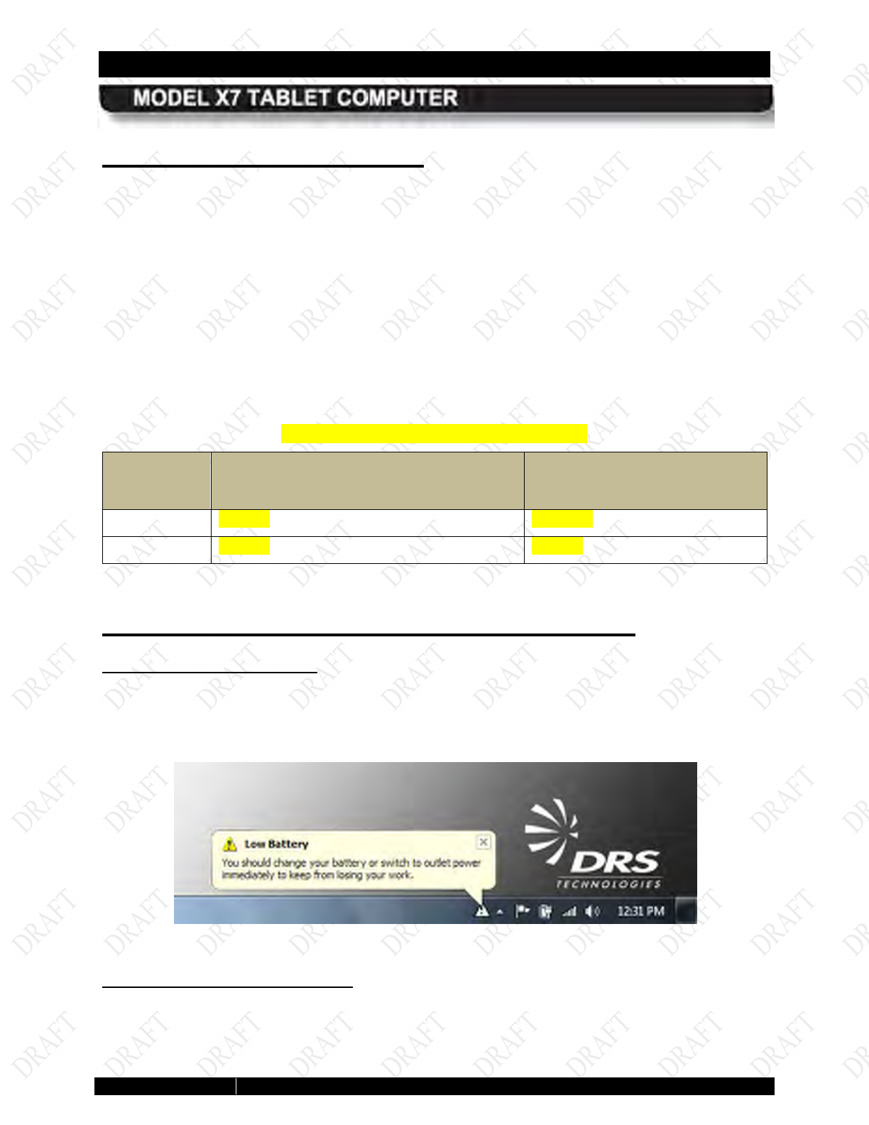
SECTION 9 BATTERY MANAGEMENT PAGE 183
9711-26400-0001
EXPORT CONTROLLED – SEE PAGE 3
Rev -
The length of time your X7 can operate on batteries alone before needing a recharge is
primarily determined by the following:
Battery Operating Times
• screen brightness (backlight) setting
• wireless and GPS radio activity
• utility and software applications that are currently running
• temperature extremes
• number of batteries (1 or 2)
• battery capacity (2-cell vs. 4-cell)
Just like people, no two batteries have the same operating characteristics. Table 33 lists typical
operating times for one or two new, fully-charged 2-cell and 4-cell batteries.
Table 33. X7 Battery Operating Times
Number of
Batteries
2-Cell Battery
P/N 0300-50842-0001
4-Cell Battery
P/N 0300-50842-0000
2
x hours
8+ hours
1
x hours
x hours
Operating under Low Battery Conditions
Your ARMOR X7 is designed to operate even when the battery is depleted (<10% charge).
When the total charge drops below 10% (low battery level), a low battery alert message will be
displayed, as shown in
Low Battery Level Alarm
Figure 86. At this point, DRS recommends you connect external power
to recharge the batteries or replace one or both batteries with fresh batteries.
Figure 86. Low Battery Alert Message
When the remaining charge reaches 7% (reserve battery level), another message will be
displayed stating that you are operating on reserve power. At this point, you need to save your
work and then connect external power, replace the batteries or shut down the computer.
Reserve Battery Level Alarm
SECTION 9 BATTERY MANAGEMENT PAGE 184
9711-26400-0001
EXPORT CONTROLLED – SEE PAGE 3
Rev -
When the remaining charge reaches 5% (critical battery level), the battery icon in the task tray
will indicate a critical battery level and Windows will automatically place your computer into
hibernation mode. Hibernation is a low-power mode that first saves your current session to
storage and then performs an orderly shutdown. To resume your session where you left off,
press the Power button to restart the computer.
Critical Battery Level Alarm
CAUTION!
If the total battery charge drops to 3% or lower while the computer
is operating, the computer will shut down abruptly with the loss of
any work in progress. Normally, the automatic shutdown at the 5%
point will prevent this happening, but heavy demands on the
batteries may cause the battery charge to drop too quickly for the
computer to react and perform a safe shutdown.
DRS recommends you do one of the following immediately should you get a low battery alert:
What to Do if You Get a Low Battery Alert
• Connect external power and begin recharging the batteries
• Replace one or both of the batteries with a fully charged battery.
• Save your work and perform a normal system shutdown.
The following suggestions will help avoid an overly-discharged condition.
Avoiding Overly-Dis charging Your Batteries
• Do not store the X7 for long periods with the batteries installed. Even when the unit is
powered off, the tablet still draws a small amount of power from the batteries.
• Do not store X7 batteries in a fully depleted condition for long periods of time. The X7
batteries will further self-discharge over time at a rate of about 10% a month or 3% every
10 days. The batteries should be recharged to 40% of full charge every 3-4 months of
storage.
The Armor Tablet X7 has an internal Level 2 smart battery charger. One of the features of this
charger is that it will attempt to recover a battery that has been too deeply discharged (3% or
less). This is done by applying a trickle current of 80 milliamps for about 3 minutes. This process
normally injects enough energy into the battery to allow normal re-charging to occur. If the
recovery process is successful, the 20% LED will begin flashing or be on steady. Allow the
battery to charge normally.
What to Do for Overly-Discharged Batteries
If this recovery process does not work (20% LED will not light), perform the procedure in Table
34.
SECTION 9 BATTERY MANAGEMENT PAGE 185
9711-26400-0001
EXPORT CONTROLLED – SEE PAGE 3
Rev -
Table 34. Recover an Overly-discharged Battery.
STEP ACTION
1.
Remove both batteries.
2.
Wait 5 seconds.
3.
Reinstall both batteries.
4.
Repeat steps 1-4 up to a maximum of five times.
5.
If the batteries still fail to start re-charging, they will have to be replaced.
A battery’s “capacity” is it’s ability to deliver a specified amount of energy in the form of electrical
current to the system over a one-hour period, measured in milliamps per hour or mAh. A
battery’s “charge” is the percentage of this capacity that has been restored to the battery. A fully
charged battery is one that can supply 100% of its current maximum capacity.
Battery Capacity and Charge
Capacity gradually decreases over time due to chemical aging, temperature extremes and
usage. Once a battery’s maximum capacity (see Battery 1 and 2 Information Buttons) drops
below 80% of its designed rating, it is considered to be at the end of it’s life and is normally
replaced. For example, a 5900 mAh hour battery should be replaced when it’s Maximum
Capacity drops below approximately 4720 mAh.
While some batteries may still be usable below the minimum capacity level, the risk for battery
failure and/or unexpected shutdown increases dramatically.
CAUTION!
Permanent battery capacity loss is greatest at elevated
temperatures with the batteries fully charged.
Do not leave
batteries installed in your X7
in high temperature surroundings
with external power connected for days or weeks at a time.
Remove the batteries and store them in a cool place.
Lithium ion batteries do not need to be deeply discharged periodically to maintain capacity like
certain other types of rechargeable batteries. In fact, deep discharges have a negative effect on
a lithium ion battery’s capacity and operating life.
Discharge/Recharge Cycles
SECTION 9 BATTERY MANAGEMENT PAGE 186
9711-26400-0001
EXPORT CONTROLLED – SEE PAGE 3
Rev -
Each time a lithium ion battery is deeply discharged (< 30%) and then recharged (either during
normal operation or conditioning), the system records the event as a “cycle.” Each of these
deep discharge/recharge cycles has a small cumulative effect on the overall capacity and life of
the battery and, on average, after approximately 300-400 cycles at nominal room temperature,
the battery is a candidate for replacement (sooner if used primarily in high temperatures).
The accumulated cycles are recorded in the Charge Cycles Count field of each Battery
Information window in ARMORutils (see Figure 51).
Battery conditioning is only recommended if you notice that the levels reported by Windows or
ARMORutils are consistently different from battery fuel gauge readings, as conditioning adds to
the charge cycle count.
Battery Conditioning
Battery conditioning is a 3-step process consisting of an initial full charge, followed by a full
discharge and finally followed by a full recharge. Each step is displayed in the Conditioning
Status panel of the ARMORutils Battery Conditioning window (see Figure 87).
Follow the procedure in Table 35 to condition a battery.
NOTE
You must have external power connected to condition a battery.
NOTE
The conditioning process can take 3-
5 hours to complete. Ensure
that external power remains connected for
the duration of the
conditioning period.
NOTE
If the internal battery temperature exceeds 45°C during conditioning,
the charging circuit will suspend the conditioning cycle until the
temperature drops back into the normal operating range.
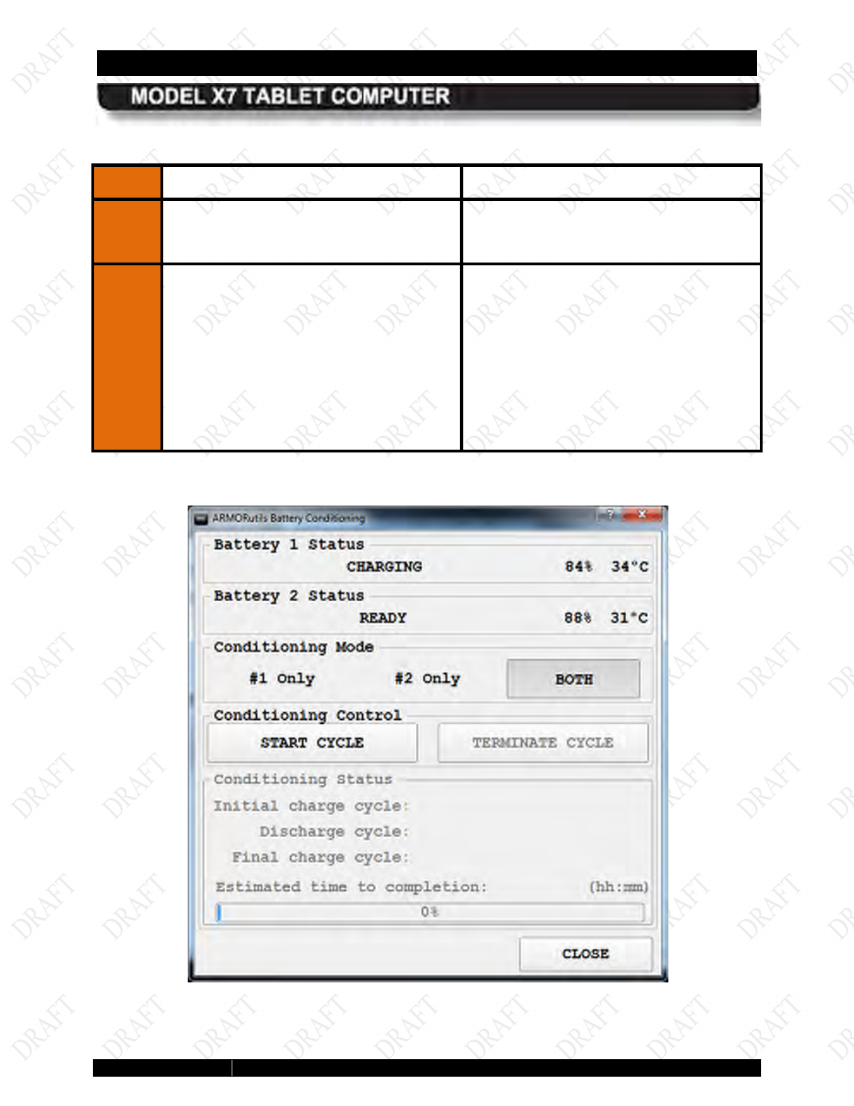
SECTION 9 BATTERY MANAGEMENT PAGE 187
9711-26400-0001
EXPORT CONTROLLED – SEE PAGE 3
Rev -
Table 35. Conditioning a Battery
STEP ACTION CONDITION OR INDICATION
1.
Connect external power to the X7, either
with the included AC adapter or through a
docking station.
2.
Select Start à ARMORutils à Battery
Monitor and click on the Conditioning
Menu button.
The Battery Conditioning window opens,
as shown in Figure 87.
NOTE: The current conditioning mode
shown is from a previous conditioning
cycle. It is not determined by whether
only one or both batteries are present.
NOTE:
The term “Ready” means the
battery is in a waiting state. It’s next state
may be charging or discharging.
Figure 87. ARMORutils Battery Conditioning Window
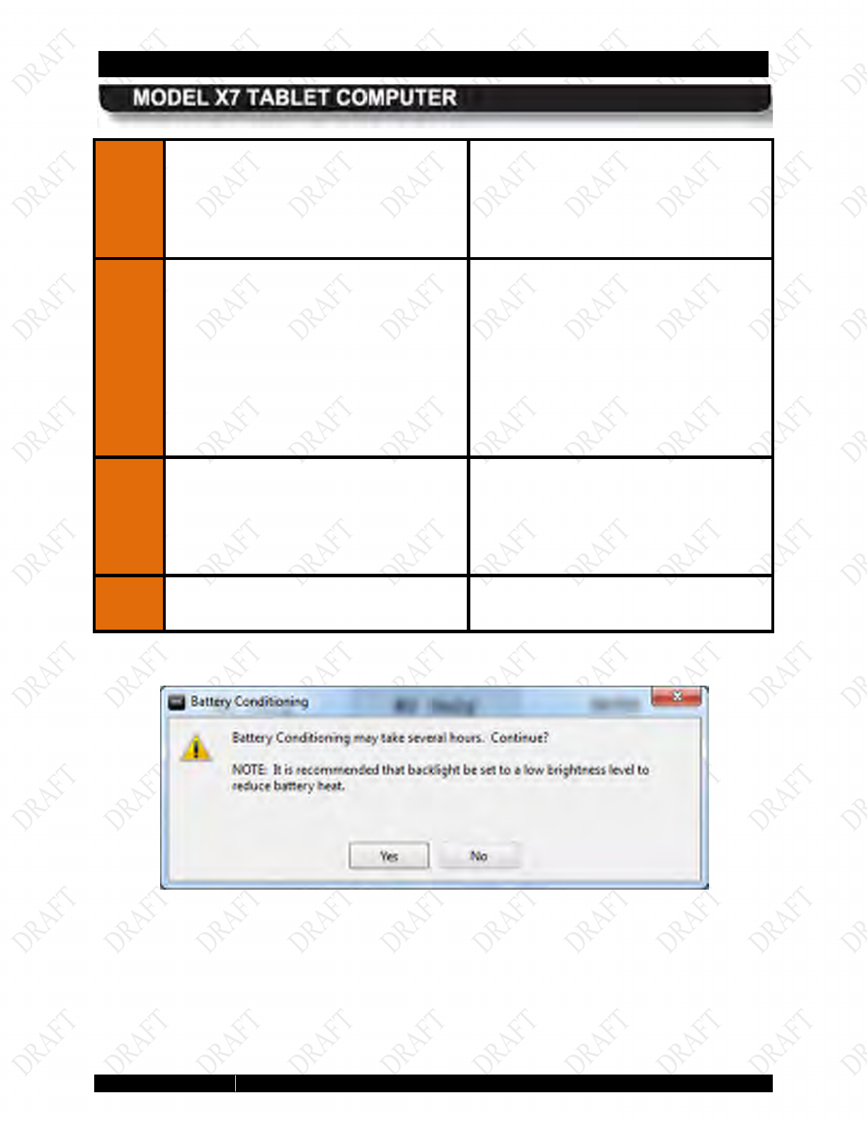
SECTION 9 BATTERY MANAGEMENT PAGE 188
9711-26400-0001
EXPORT CONTROLLED – SEE PAGE 3
Rev -
3.
Select #1 Only, #2 Only or Both NOTE:
If only one battery is installed,
selecting that battery will cause the
START CYCLE option to appear in dark
text; if you select the missing battery or
BOTH, the START CYCLE
option will
appear in grayed out text.
4.
Select START CYCLE. An alert window will appear as shown in
Figure 88.
NOTE: To reduce internal heating during
the conditioning cycle, DRS
recommends you turn down the backlight
level (brightness) as much as practical.
NOTE: If the internal battery temperature
exceeds 45°C. the computer will abort the
conditioning process.
5.
Click on Yes to proceed or No to cancel
the conditioning. The first charge cycle will begin. The
following table lists the approximate
charge times for both the 2-cell and 4-cell
battery.
6.
To terminate the conditioning process at
any time, click on Terminate Cycle.
Figure 88. Battery Conditioning Start Alert Message
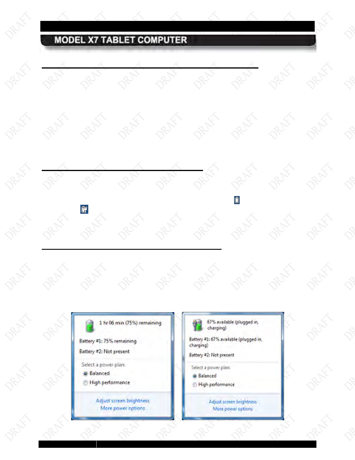
SECTION 9 BATTERY MANAGEMENT PAGE 189
9711-26400-0001
EXPORT CONTROLLED – SEE PAGE 3
Rev -
The total operating time for your ARMOR X7 is greater than 8 hours with two batteries installed
and up to 4 hours with a single battery. However, this is dependent on a variety of factors
including temperature, backlight setting and computer usage.
How to Optimize Battery Operating Time
You can help ensure the maximum performance of your batteries by optimizing your computer’s
power management features. For some suggested ways to do this, select Start à Control
Panel à Hardware and Sound and click on the Power Options icon.
There are two power plan options: Balanced, High Performance and Power Saver. DRS
recommends that you use the Balanced plan until you are more familiar with the usage
demands on your tablet.
You can monitor the charge level of each battery in two ways:
How to Monitor Battery Usage
1) by clicking on the Battery/Plug icon in the task bar to open a desktop battery monitor
window similar to the one shown in Figure 89. The battery icon changes to a battery with
plug icon when external power is connected.
2) by selecting the Battery Monitor option on ARMORutils Main Page to open the Battery
Monitor dialog window.
Click on the Battery/Plug icon in the Windows task tray to open the desktop battery monitor
window, (see examples in
The Des ktop Battery Monitor Window
Figure 89). The example on the left shows the battery symbol and
remaining charge when the X7 is operating on battery power alone. The example on the right
shows the battery symbol and remaining charge when external power is connected and the
battery is charging.
The total charge remaining or available for two batteries is determined by the following formula:
Batt #1 % + Batt #2 % / 2 .
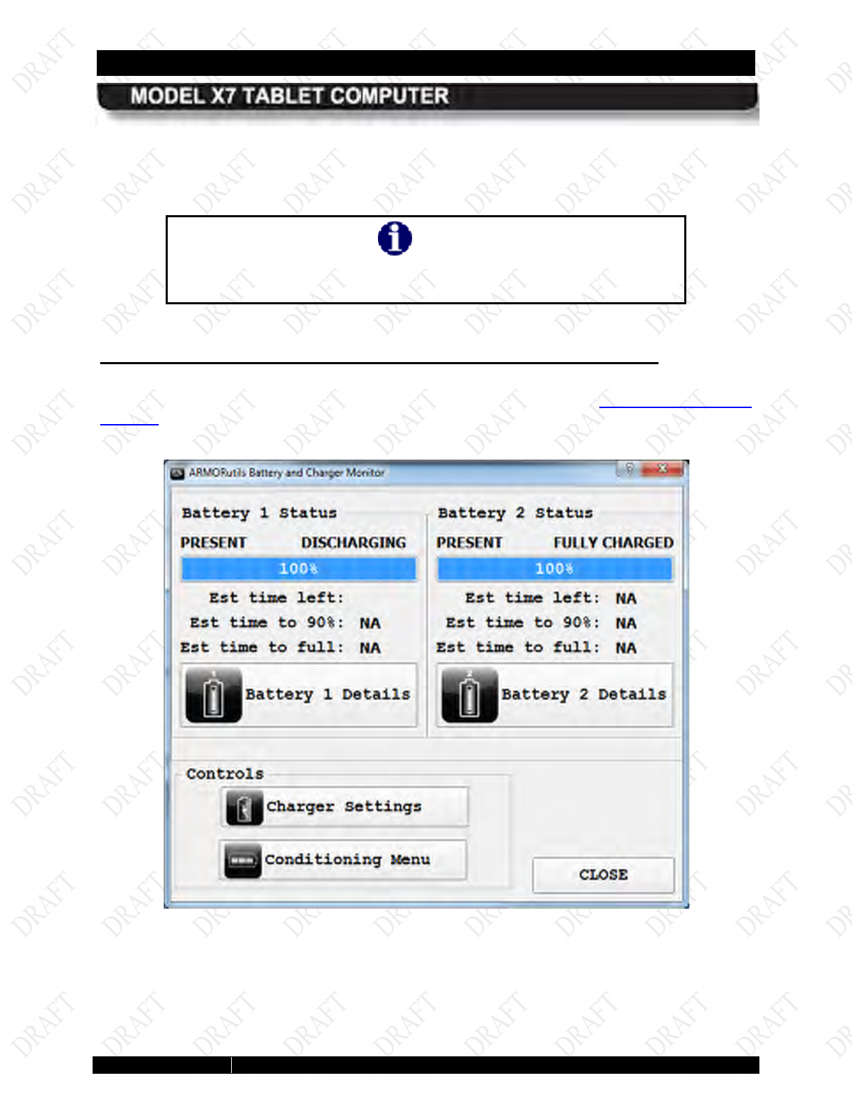
SECTION 9 BATTERY MANAGEMENT PAGE 190
9711-26400-0001
EXPORT CONTROLLED – SEE PAGE 3
Rev -
Figure 89. Windows Battery Monitor Examples
NOTE
You must restart the window to see any recent changes, such as that
resulting from removing a battery or plugging in external power.
Double-click on the ARMORutils icon on the desktop and select the Battery Monitor button to
open the Battery Monitor dialog window, as shown in
The ARMORutils Battery Monitor Dialog Window
Figure 90. Refer to Battery Monitor Dialog
Window
for a description of this page.
Figure 90. ARMORutils Battery Monitor Page
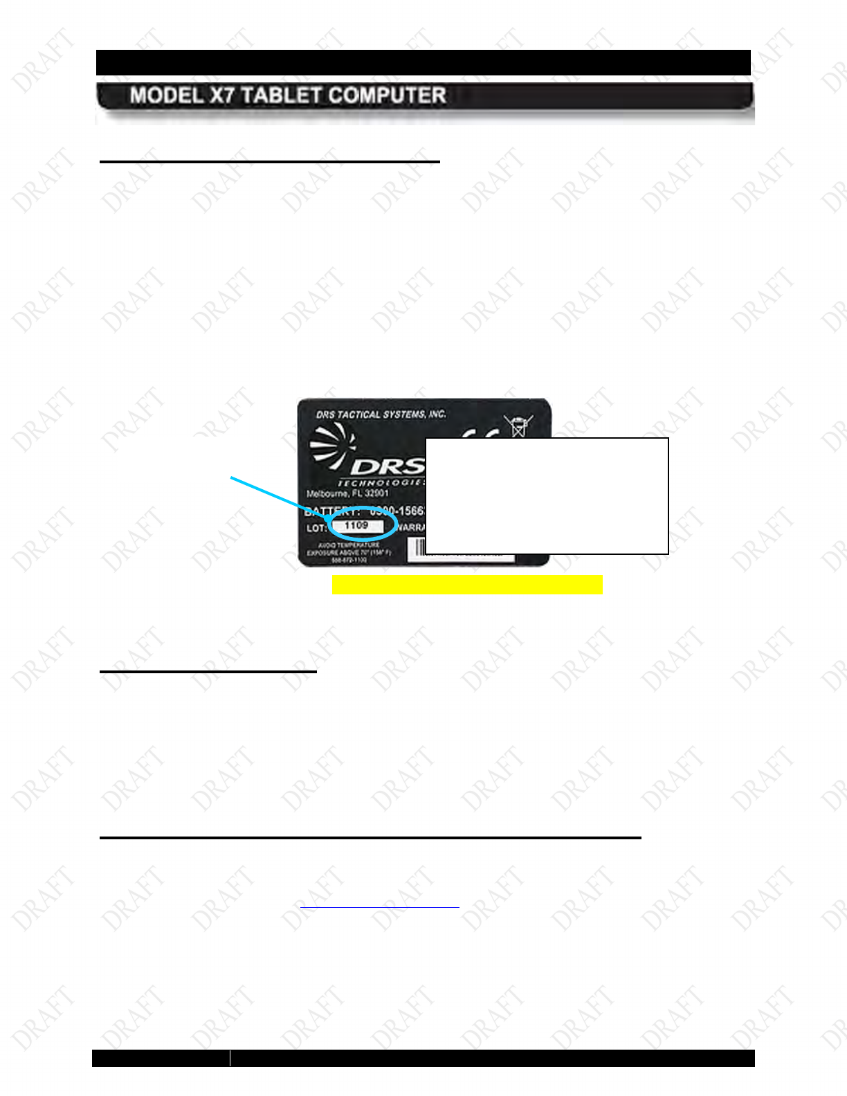
SECTION 9 BATTERY MANAGEMENT PAGE 191
9711-26400-0001
EXPORT CONTROLLED – SEE PAGE 3
Rev -
Battery life is affected by the age of the battery, its operating temperature and the number of
discharge/charge cycles that it goes through over time. Industry surveys report that “average
daily use” (8 hours or less at nominal room temperature) equates to approximately 300-400
cycles per year. Batteries operating at this level of usage that are properly cared for can last as
long as two years or even longer. However, if the batteries are in constant use (24/7), subjected
to frequent temperature extremes or are subjected to complete discharging frequently they will
deteriorate more rapidly. Under these conditions, DRS recommends at least an annual
replacement.
When to Replace a Battery
To determine the age of the battery, check the lot number on the battery label (see Figure 91).
This number is the date (mm/yy) the battery was shipped from DRS.
Figure 91. ARMOR X7 Battery Label Example
Your X7 battery is warranted against all defects in material and workmanship for a period of 1
year from shipment from DRS.
Battery Warranty
Because of the many variables associated with usage and aging, DRS is not responsible for
battery capacity performance except as affected by factory defects or workmanship in the
battery.
Your ARMOR X7 uses long lasting Lithium Ion batteries that are custom made for DRS Tactical
Systems, Inc. If you need to purchase replacement batteries, notify your sales representative,
authorized reseller or contact
Where to Purchase Replacement Batteries
DRS Technical Support.
Do not substitute any other batteries. Substituting batteries could damage the X7 and may void
your computer warranty.
SHIPPING
DATE
NEED NEW LABEL IMAGE
SECTION 9 BATTERY MANAGEMENT PAGE 192
9711-26400-0001
EXPORT CONTROLLED – SEE PAGE 3
Rev -
The following storage tips will help you optimize the capacity and performance of your batteries.
How to Store Batteries When Not in Use
• If your X7 will not be in use for 7-30 days, it is recommended that the batteries first be
charged and then removed from the computer for short-term storage.
Short-Term Storage
• Batteries can be stored at temperatures of 32ºF to 95ºF (0ºC to 35ºC) and a humidity of
45-85%
• When possible, store them in a cool dry place at room temperature (25°C/77°F) or
below.
• Do not leave batteries in direct sunlight or in any other unusually hot location. A battery
will deteriorate more quickly if stored in high temperatures such as a vehicle in the hot
sun.
• Protect the battery contacts from accidentally touching other battery contacts or any
metal objects to prevent a short circuit and possible arcing or explosion.
• If your X7 will not be in use for 30 days or longer, the batteries should be placed in long-
term storage.
Long-Term Storage
• Prepare the batteries for storage by placing them in the computer with external power
disconnected and allow the charge to drop to 40%.
• LiION batteries self discharge at the rate of about 10% per month. While in long-term
storage, you should recharge the batteries every 3-4 months to a charge level of 40%.
• To check a battery’s remaining charge, insert it in the X7, power up the unit and select
the Battery Monitor button from the ARMORutils main window.
• Recharge a battery within 24 hours of a full discharge. Batteries remaining in a fully
discharged state longer than 24 hours may deteriorate more quickly.
Battery Tips for Best Performance
• Battery charging should be done at temperatures between 32°F (0°C) to 95°F (35°C),
but preferably at room temperature. The battery could deteriorate more quickly when
charged at high temperatures.
• When operating your ARMOR X7 on external power for extended periods of time (1
week or longer), it’s best to remove the batteries and store them in a cool place until
needed.
• If batteries are removed for longer than 30 days, refer to How to Store Batteries When
Not in Use.
• If possible, allow a battery to warm or cool to the temperature of your surroundings
before installing it in the tablet.
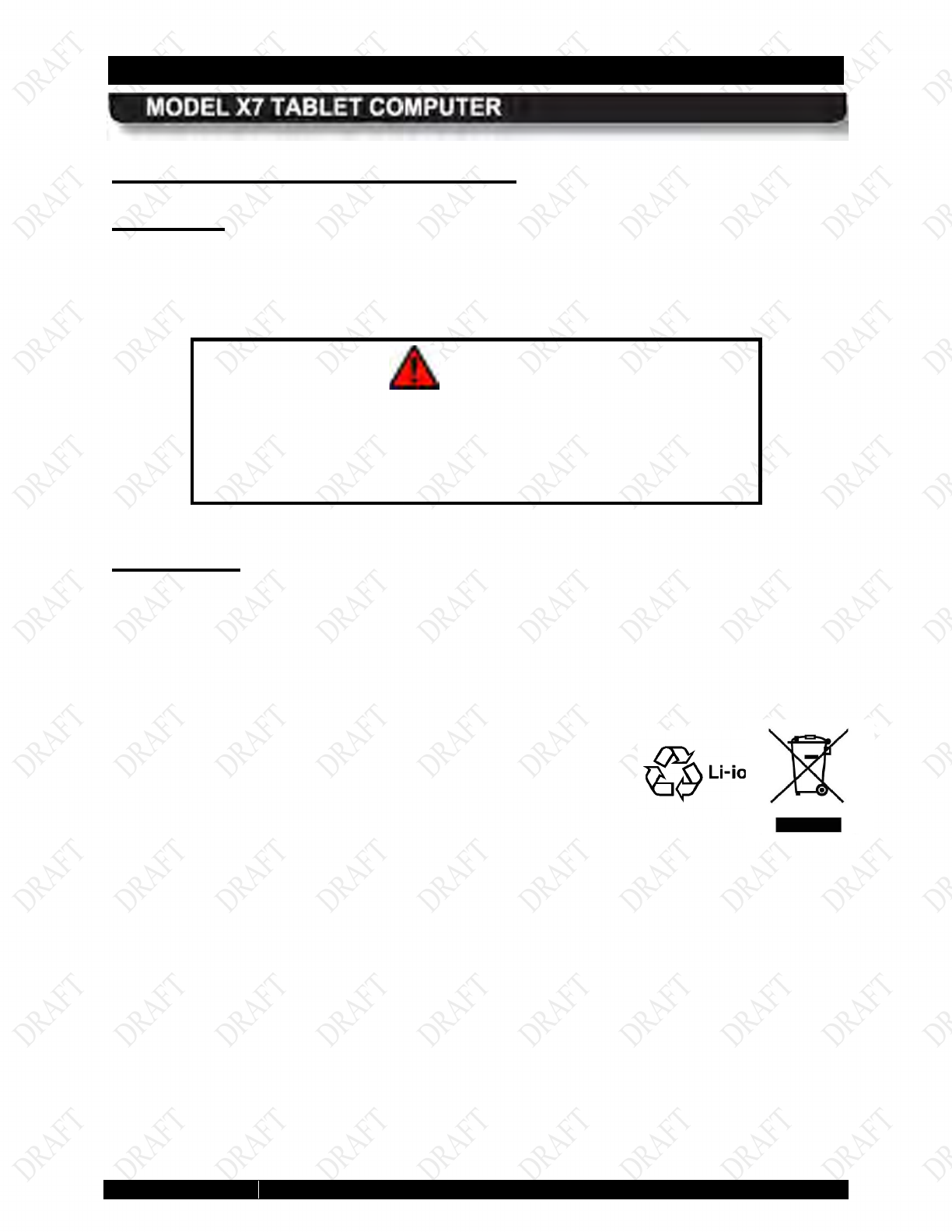
SECTION 9 BATTERY MANAGEMENT PAGE 193
9711-26400-0001
EXPORT CONTROLLED – SEE PAGE 3
Rev -
Disposing Of Your Batteries
You can dispose of your X10gx batteries in a normal waste receptacle. However, they contain
recyclable materials that can be extracted and used again. Please see the section on recycling
below.
Dis pos al
WARNING!
Disposed lithium-ion batteries that are not fully discharged contain
active salts that can result in an explosion if suddenly exposed to
moisture or water in the environment. To prevent possible injury to
someone finding the battery, please ensure it is fully discharged
before disposing in a domestic or commercial garbage receptacle.
Lithium-ion batteries are fully recyclable and should not be simply thrown away. Please help
protect our environment by turning in your defective batteries to an authorized recycler, or
sending them back to DRS.
Recycling
DRS Tactical Systems supports recycling of batteries and will take back your batteries using a
Returned Material Authorization (RMA) form. Please contact the DRS Technical Support center
toll-free at 1-888-872-1100 for more information.
Follow these precautions when handling or returning used batteries:
• Insulate the battery contacts with tape.
• Do not disassemble the batteries.
• Package the batteries so that they cannot move around or
make contact with each other.

SECTION 9 BATTERY MANAGEMENT PAGE 194
9711-26400-0001
EXPORT CONTROLLED – SEE PAGE 3
Rev -
This Page Intentionally Left Blank

SECTION 10
TECHNICAL SUPPORT
PAGE 195
9711-26400-0001
EXPORT CONTROLLED – SEE PAGE 3
Rev -
10. DRS TECHNICAL SUPPORT
Please have your local technical personnel check for network or custom software problems
before contacting DRS Technical Support with a problem.
Before You Contact Us
Before proceeding, please read the
How to Obtain Warranty Service
Error! Reference source not found..
Notice: DRS reserves the right to charge a No Fault Found (NFF) fee for any unit returned for
repair that is found to be fully operational.
1. Immediately notify DRS.
Inform DRS of your problem at one of the numbers below, or notify an authorized DRS Reseller.
In North America, call: (888) 872-1100 or (321) 309-0599 – 24 hrs, 7 days a week
In the UK, call: 44-(0)-1252-730716
In Europe, call: 49-2246-915-99-77
2. Obtain a Return Merchandise Authorization (RMA) Number.
If it is determined that your product needs to be returned for replacement or repair, a customer
service representative will give you an RMA number. The RMA number is required to return any
product to DRS, regardless of the reason for the return.
3. If you want to use our online RMA service, please ask for a Username and Password.
To access our online RMA service:
1) Go to www.drsarmor.com.
2) Click on the Support tab and select Online RMA.
3) At the login screen, enter your Username and Password.
4) Click on Send.
5) Fill out the online form.
6) Print a copy of the form for your records.
7) Select Send.
4. Include the Following Required Information with Your Product(s):
• Company name, address and telephone number.
• RMA number received from DRS (if applicable).
• Serial number of the product.
• Date of purchase.
SECTION 10
TECHNICAL SUPPORT
PAGE 196
9711-26400-0001
EXPORT CONTROLLED – SEE PAGE 3
Rev -
• Your ship-to address and any special shipping requirements.
• A detailed description of the problem.
5. Prepare your Products for Shipment.
• Back up any important data on the X7 storage media (solid-state drive, mSATA drive,
SD card).
• Use the original shipping container if possible to return your product.
• Remove the batteries and package them separately.
• If the original container is not available, wrap each item securely with bubble wrap or
suitable cushioning material.
• Enclose a copy of the RMA form.
• Enclose a description of the problem and any special notes for the repair technician.
6. Ship Your Product(s).
Ship your products to one of the addresses listed below:
NOTE
Transportation and insurance costs must be prepaid
. DRS is not
responsible for loss or damage which may occur in transit.
NOTE
Before you ship any product(s) to DRS, be sure to back up the data on
the X7 storage media.
Remove any confidential, proprietary or
personal information and any removable media such as floppy disks,
CDs or PC Cards. DRS is not responsible for any lost confidential,
proprietary or personal information, removable media or for corrupted
data.
In North America, ship to: DRS Tactical Systems, Inc.
1110 West Hibiscus Boulevard
Melbourne, Florida 32901 USA
ATTN: Service
In Europe, ship to: DRS Tactical Systems, LTD.
The Trading Estate
Farnham Surrey, GU9 9NN UK
ATTN: Brian Perkins
SECTION 10
TECHNICAL SUPPORT
PAGE 197
9711-26400-0001
EXPORT CONTROLLED – SEE PAGE 3
Rev -
or: International – Markus Breuch
Rathausstr. 10
53797 Lohmar, Germany
ATTN: Silke Zaigler
Once your product(s) are repaired or replaced under the terms specified in the warranty, DRS
will return your product(s), with shipping pre-paid, to the address included with your RMA.
Please call us, fax us, email us, or visit our website.
If You Need Further Information
Call us: In North America, call: (888) 872-1100 or (321) 309-0599
In the UK, call: 44-(0)-1252-730716
In Europe, call: 49-2246-915-99-77
Fax us: In North America: 321-725-0496
In the UK, fax: 44-(0)-1252-730522
In Germany, fax: 49-2246-915-99-78
Email us:
For Support: In North America or UK: support@drs-ts.com
In Europe: sales@drsarmor.eu
For Sales and Information
In North America or UK: Sales@drsarmor.com
In Europe, email: Sales@drsarmor.eu
Or Visit our website at: www.drsarmor.com
For translation in German, click on “Deutsch” at the top of
the page.

SECTION 10
TECHNICAL SUPPORT
PAGE 198
9711-26400-0001
EXPORT CONTROLLED – SEE PAGE 3
Rev -
DRS TACTICAL SYSTEMS, INC.
Warranty Information
LIMITED WARRANTY – HARDWARE
ARMOR PRODUCTS
DRS Tactical Systems, Inc. (“DRS”) warrants for the duration of this warranty that the DRS ARMOR product(s) (“Product(s)”)
produced by DRS will be free from defects in material and workmanship under normal use and service, subject to the terms and
conditions set forth herein. This warranty applies to the Products only and excludes, but is not limited to, all other products and
accessories supplied and/or distributed but not manufactured by DRS.
General Information
This warranty extends only to the original purchaser of Products from DRS or a DRS Authorized Reseller (“Original Purchaser”). It
is not transferable to anyone who subsequently purchases or obtains the Products from the Original Purchaser.
The warranty is valid for a period of three (3) years from the original date of the packing slip from DRS and/or an Authorized
Reseller. During this period, DRS will, at its option and expense, either repair or replace with new or reconditioned (of equal or
better quality) parts of any of the Products which prove to be defective, provided that such Products are returned in accordance with
the terms of this warranty. All exchanged parts and Products replaced under this warranty will become the property of DRS. If
repair or replacement is not feasible, DRS will, at its option, refund the purchase price of the Product(s) on a three year straight line
depreciation basis. Any replacement part or Product will be warranted for the remainder of the original warranty period or ninety (90)
days, whichever is longer.
Length of Warranty
This warranty covers defects in materials and workmanship in the Products, as follows:
Terms and Conditions
Term 3 years standard
Technical Assistance Yes
Shipping Costs Shipping costs of a Product to DRS are not included as part of this Warranty. Shipping
costs of a Product to the Original Purchaser after a warranty repair is included as part of this
warranty. If after receipt of a Product for repair under this warranty, it is later determined to
be a non-warranted repair, all shipping costs are to be paid by the Original Purchaser.
Non-DRS ARMOR products (accessories) under the original manufacturer’s warranty including, but not limited to, the carrying
case, PCMCIA cards, etc. Non-DRS ARMOR branded products are not covered under an extended warranty period.
This warranty does not cover:
Software, including the operating system and software added to the DRS ARMOR hardware products through our factory-
integration system, third-party software, or the reloading of software;
Scratches or abrasions to the Product’s LCD screen/display, and abusive wear of the LCD screens;
Consumables and High Wear Items. Batteries, Keyboards, Touch Pad, Touch Screen, AC Adaptor, and liquid crystal display
(LCD) are covered under the Limited Warranty for one (1) year.
Problems that result from external causes such as accident, fire, floods, or acts of God; abuse; misuse; or problems with
electrical power; servicing not authorized by DRS; failure to follow the Product instructions or failure to perform preventative
maintenance; problems caused by using accessories, parts, or components not supplied by DRS; improper installation (to
include the absence of surge protection in vehicle installations), testing, operation, use or handling of the Product; or
unauthorized alteration of Products
Products with missing or altered service tags or serial numbers.
Products for which DRS has not received payment.
DRS is not responsible for and shall not be liable for transportation and insurance charges incurred in or damages resulting
from transporting the Products, Accessories and/or Replacement Products to DRS for warranty service.
DRS is not responsible for any third-party software created for use in the integration and/or operation of any Products,
Accessories and/or Replacement Products whether or not such third party software was installed by DRS. Maintenance and
support service for third-party software is the sole responsibility of the creator thereof.

SECTION 10
TECHNICAL SUPPORT
PAGE 199
9711-26400-0001
EXPORT CONTROLLED – SEE PAGE 3
Rev -
The agents, dealers, DRS Authorized Resellers and employees of DRS are not authorized to make any modifications to this
warranty, or additional warranties binding on DRS about or for Products, Accessories and/or products sold or supplied by DRS.
Additional statements, whether oral or written, except signed written statements from an officer of DRS, do not constitute warranties
and should not be relied upon.
Additional Information
The Product is not designed or certified for use in high risk applications including, but not limited to, the operation of nuclear
facilities, aircraft navigation or air traffic control systems, communications systems in which a failure thereof could cause death or
serious injury or property damage (e.g., emergency or 911 communications systems), medical systems, life support, weapons
systems or any other potentially life critical uses. Original Purchaser understands and agrees that DRS makes no assurances or
warranties that the Product is suitable for any such high risk uses.
DRS’ SOLE LIABILITY, AND ORIGINAL PURCHASER’S SOLE REMEDY, FOR ANY MALFUNCTIONS AND DEFECTS IN THE
PRODUCTS IS LIMITED TO REPAIR AND REPLACEMENT AS SET FORTH IN THIS WARRANTY STATEMENT. EXCEPT AS
OTHERWISE EXPRESSLY STATED HEREIN, DRS DISCLAIMS ALL OTHER WARRANTES, WHETHER EXPRESS OR IMPLIED,
INCLUDING BUT NOT LIMITED TO ANY IMPLIED WARRANTIES OF MERCHANTABILITY AND FITNESS FOR A PARTICULAR
PURPOSE, AND ANY IMPLIED WARRANTIES OTHERWISE ARISING FROM COURSE OF DEALING OR TRADE. NO
WARRANTIES WILL APPLY AFTER THE WARRANTY PERIOD HAS EXPIRED.
DRS HEREBY DISCLAIMS, AND THE ORIGINAL PURCHASER HEREBY AGREES, THAT DRS DOES NOT ACCEPT LIABILITY
BEYOND THE REMEDIES PROVIDED FOR IN THIS WARRANTY OR FOR ANY INDIRECT, CONSEQUENTIAL, PUNITIVE,
SPECIAL, OR INCIDENTAL DAMAGES, INCLUDING, WITHOUT LIMITATION, ANY LIABILITY FOR THIRD PARTY CLAIMS FOR
DAMAGES, FOR PRODUCTS NOT BEING AVAILABLE FOR USE, OR FOR LOST DATA OR LOST SOFTWARE.
NOTWITHSTANDING ANYTHING CONTAINED HEREIN, DRS’ TOTAL LIABILITY FOR ANY ALLEGED OR ACTUAL BREACH OF
WARRANTY WILL BE NO MORE THAN THE AMOUNT PAID FOR THE PRODUCT THAT IS THE SUBJECT OF ANY SUCH
CLAIM. THIS IS THE MAXIMUM AMOUNT FOR WHICH DRS SHALL BE RESPONSIBLE.

REAR MATTER PAGE 200
9711-26020-0001
Rev -
Acronyms
ACRONYM DEFINITION
AC alternating current
BIOS basic input/output system
CD-ROM
compact disk – read only memory
CDMA code division multiple access
CPU
central processing unit
DC direct current
DVD digital video disk
EDGE
enhanced data rates for GSM evolution
EVDO evolution data only/evolution data optimized
GB
gigabytes
GPRS general packet radio service
GPS global positioning system
GSM
global system for mobile communications
HSDPA high-speed downlink packet access
I/O
Input/Output
LCD liquid-crystal display
LED light-emitting diode
OEM
original equipment manufacturer
PC personal computer
PCMCIA
personal computer memory card international association
RAM random access memory
SAS security attention sequence
SD
secure digital
SIM subscriber identity module
SmBus
system management bus
SODIMM small outline dual in-line memory module
SSD solid-state drive
SVGA
super VGA (maximum of 800 x600 pixels)
TFT thin-film transistor
USB
universal serial bus
VAC volts AC
VDC volts DC
VGA
video graphics array
WLAN wireless local area network
WWAN
wireless wide area network
XGA extended VGA (1024 x 768 pixels)

REAR MATTER PAGE 201
9711-26400-0001
EXPORT CONTROLLED – SEE PAGE 3
Rev -
Glossary
TERM DEFINITION
ambient temperature The temperature of the air surrounding an object
depleted battery A lithium-ion battery that has discharged to a level between 10%
and 3% of charge, as indicated by a flashing 10% LED on the
Battery Gauge.
fully charged battery A lithium-ion battery that has reached 100% of charge as indicated
by a steady 100% LED on the Battery Gauge.
fully depleted battery A lithium-ion battery that has discharged to a level of 3 % or below.
fully discharged battery Same as depleted.
flexspace A special compartment with a flexible communications interface for
custom circuit cards or modules.
storage device Any removable or fixed storage device (SSD, mSATA, SD card,
etc.) that the processing system can use for temporary or
permanent data storage.

REAR MATTER PAGE 202
9711-26400-0001
EXPORT CONTROLLED – SEE PAGE 3
Rev -
Appendix A
4th Click (Back)
Explanation of Pen Side Button Options
Duplicates a 4th mouse button click – usually the Back command in
browser application.
5th Click (Forward) Duplicates a 5th mouse button click – usually the Forward command in
browser application.
Click Duplicates a left mouse button click.
Click Lock Duplicates holding an object with the left mouse button; good for
dragging objects or selecting text or groups of objects. Press button to
grab, press to release.
Default Sets the switch function to Right Click
Disabled Disables the side switch.
Double Click Generates a double-click action with a single press of the side switch.
Erase Enables the pen tip to act like an eraser in handwriting applications
and in some paint and imaging editing programs.
Journal Opens Microsoft Journal™ (only
with versions of Windows that
include Microsoft Journal).
Keystroke… Enables you to define special keystrokes. This function can also be
made available using the Pop-up Menu option (must be defined in the
Pop-up Menu tab of the Pen Computer Properties dialog.
Middle Click Duplicates pressing the middle scroll button on a mouse.
Mode Toggle… Toggles between Pen and Mouse mode if pre-configured in the Pop-
Up Menu tab of the Pen Computer Properties dialog (see Windows
Control Panel).
Modifier… Enables you to duplicate a shift, ctrl, alt or click function.
Open/Run… Opens or runs a pre-selected application. This function can also be
made available using the Pop-up Menu option.
Pan/Scroll… Enables you to use the pen like a hand to move a document or image
in any direction within an active window.
Pop-up Menu Makes available selections enabled in the Pop-up Menu tab of the
Pen Computer Properties dialog (see Windows Control Panel).
Pressure Hold Primarily used with painting programs to maintain the pressure of a
brush stroke.
Right Click Duplicates a right mouse button click.
Computer PC Defined Uses the pen settings defined in the Pen Options tab of the Pen and
Touch dialog window.
Computer
PC Input
Panel Opens the Computer PC input panel (only with versions of Windows
that support Computer PC).
REAR MATTER PAGE 203
9711-26020-0001 Export Controlled – See Page 3 Rev -
Appendix B
The X7 battery charger can recharge a single battery in 2.5 hours and two batteries in less than
6 hours. You can remove or insert a battery at any time in the charge cycle without causing
damage to the charging circuits or to the battery.
Using the X7 External Battery Charger
Table 36. Charging a Battery
Step Action Comment
1.
Hold the battery with its connector
pointing down and the rounded edge of
the battery facing away from the
charger, as shown in Figure 92.
2. Insert the battery into the bay and gently
press down to engage the locking
latches. Rock the battery slightly to
ensure the battery is locked in place.
The battery button will snap into place
when the latch is engaged. The charging
will begin immediately, as indicated by
the steady yellow charge indicator.
When charging is complete, the yellow
LED will turn off and the green (fully
charged) LED will turn on.
3. To remove the battery, press
on the
spring-
loaded battery release button
and lift the battery from the charging
bay.
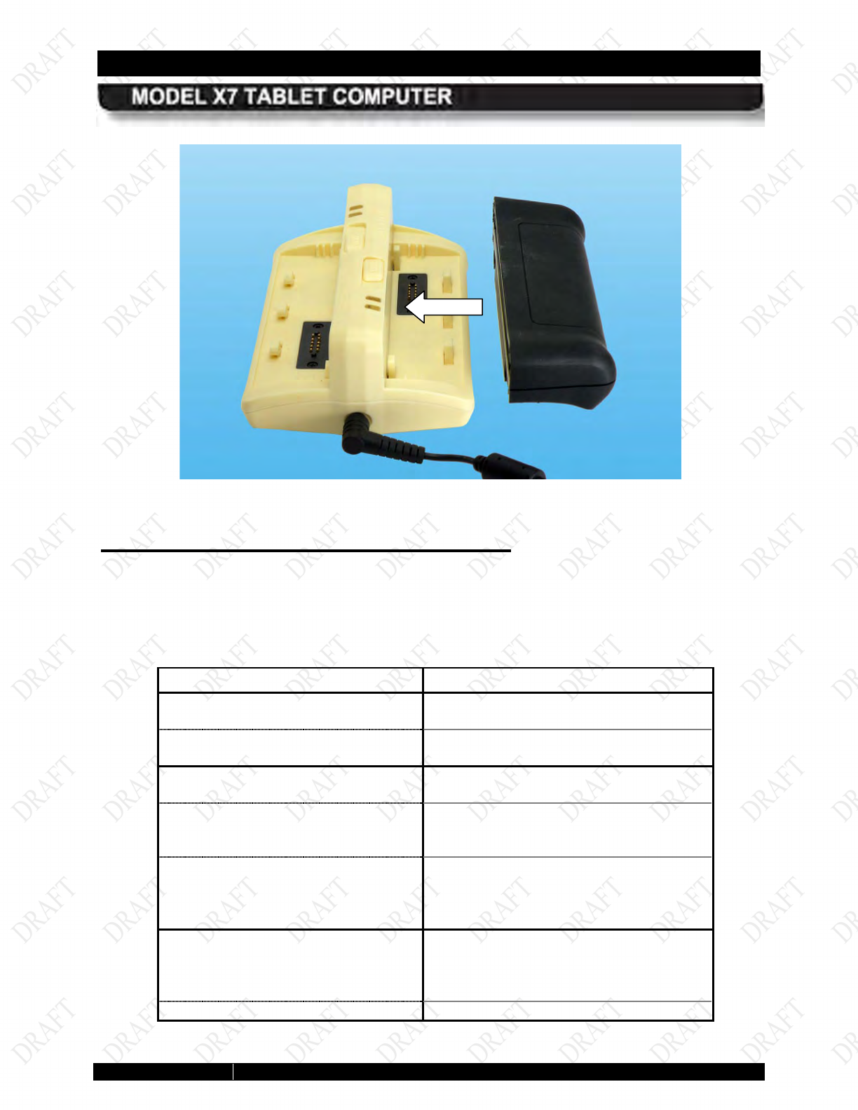
REAR MATTER PAGE 204
9711-26400-0001
EXPORT CONTROLLED – SEE PAGE 3
Rev -
Figure 92. Inserting a Battery
There are two status indicators for each battery bay.
Charger LED Status Indications
Table 37 lists the possible indicator
conditions and their meanings.
Table 37. Status Indicator Conditions
Status Indicator
Condition
Fully Charged Battery LED (green)
On steady with external power applied
and battery fully charged (>95%).
Off with external power disconnected or
battery charge <95%.
Charging LED (yellow)
On steady with external power applied
and battery charging.
Flashing 1 sec on/1 sec off with external
power applied and battery temperature
above or below maximum limits.
Flashing 1 sec on/1 sec off with external
power applied, temperature in limits,
and other battery charging (serial
charging).
Fault LED (red)
On steady when fault in power system
is detected (over voltage, under voltage,
excessive current, charger circuit failure
or battery circuit failure).
Off when fault is corrected.
REAR MATTER PAGE 205
9711-26400-0001
EXPORT CONTROLLED – SEE PAGE 3
Rev -
RECORD OF CHANGES
Rev ECO # Description Of Change
- Initial Release.

REAR MATTER PAGE 206
9711-26400-0001
EXPORT CONTROLLED – SEE PAGE 3
Rev -
This Page Intentionally Left Blank