DTC Communications DSS900TX User Manual DTC03 1 DTC03 1
DTC Communications Inc. DTC03 1 DTC03 1
UserManual.wiki
>
DTC Communications
>
DSS900TX User Manual
>
Text Users Manual
Contents
1.
Cover Sheet Users Manual
2.
Introduction Users Manual
3.
Text Users Manual
Text Users Manual
Navigation menu
Upload a User Manual
Namespaces
Wiki Guide
HTML
PDF
Info
Views
User Manual
Discussion / Help
Navigation
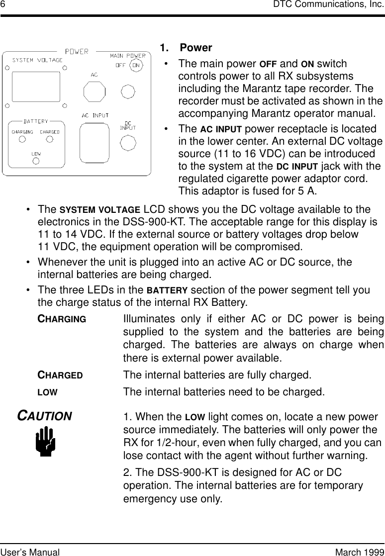
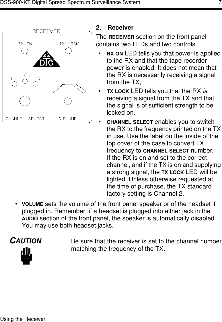
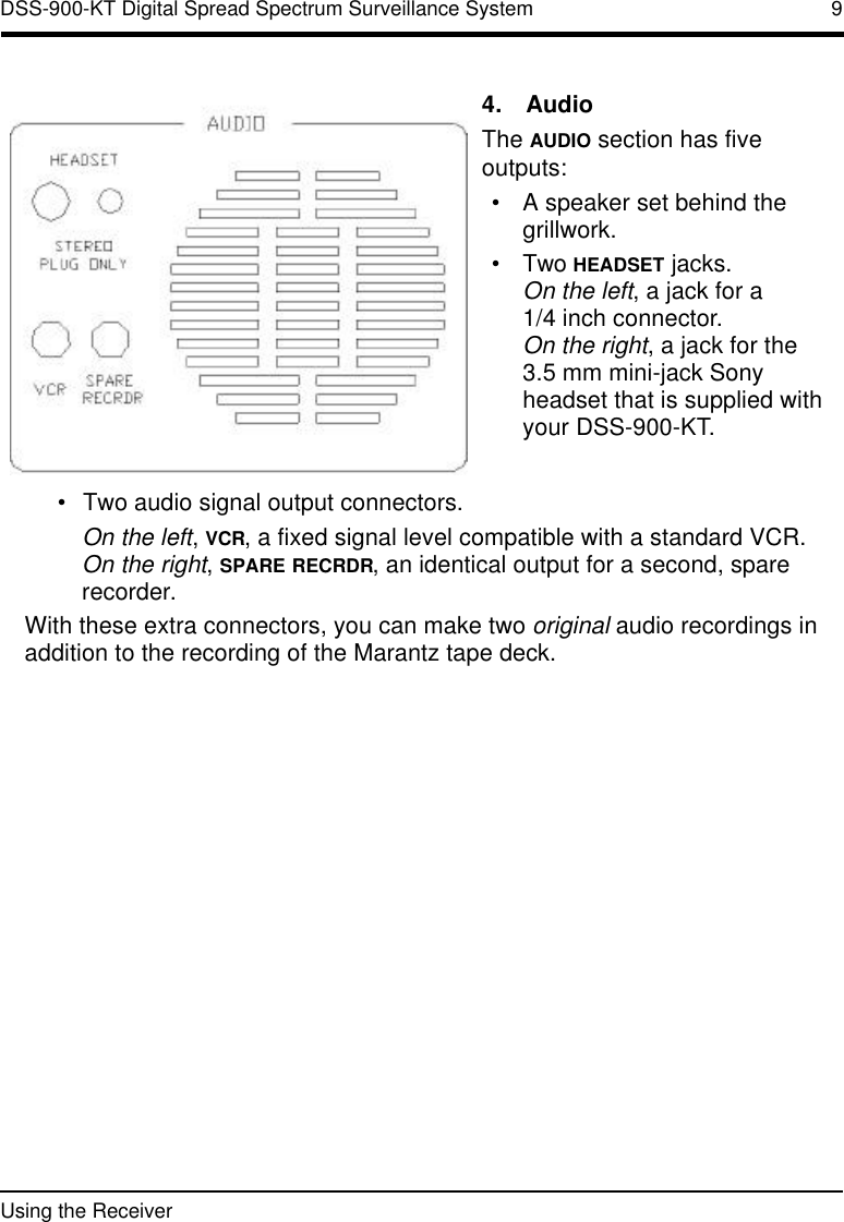
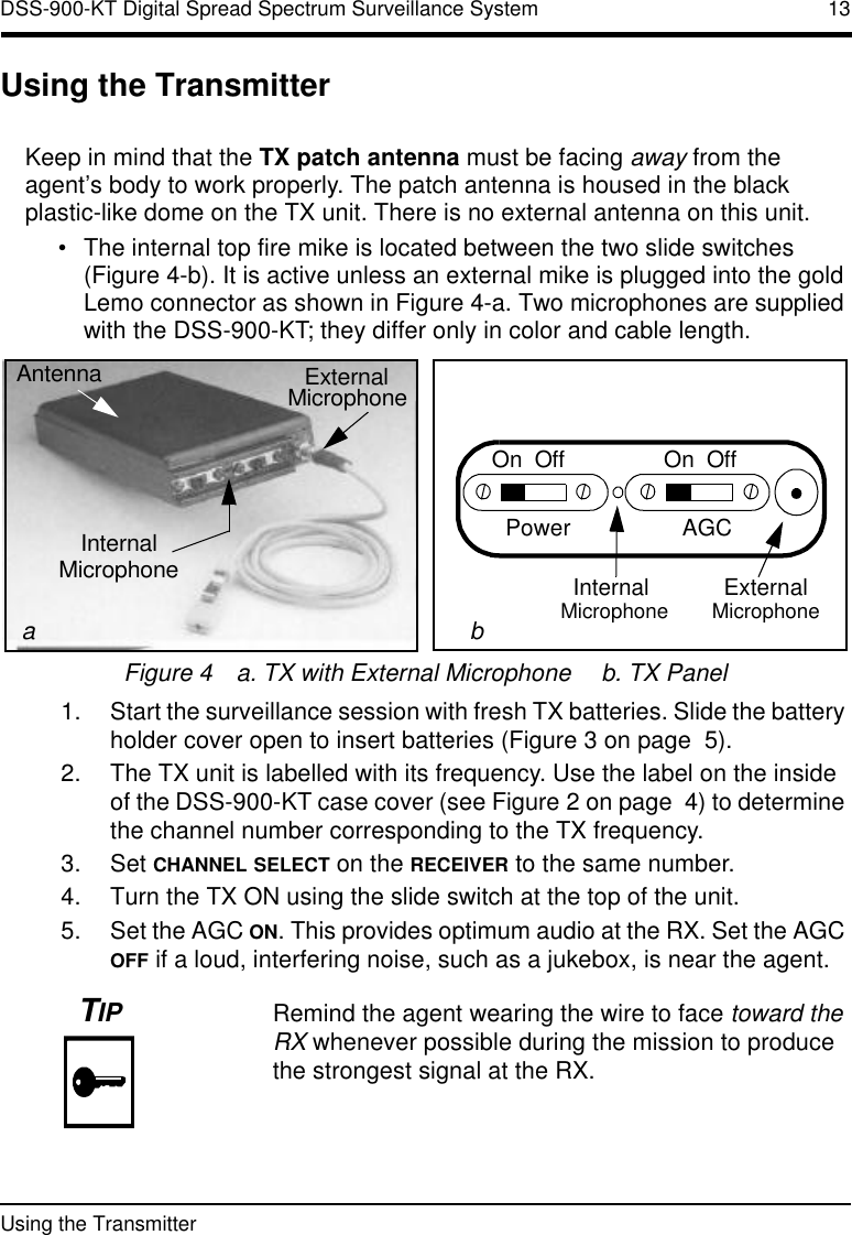
![8DTC Communications, Inc.User’s Manual March 1999Drawings and photos of the Marantz tape recorder as well as complete operating instructions are given in the Marantz operator manual that accompanies your DSS-900-KT system. The manual is stored in the accessory pouch of the DSS-900-KT.Whenever loading a tape into the Marantz recorder, make sure that:•The tape is fully rewound.•You are not about to overwrite an existing recording.•The tape is not write protected.3.RecorderThe RECORDER section contains a single LED and single switch, both of which relate to the Marantz tape recorder built into your DSS-900-KT.•POWER ON lights up when the POWER switch located below it is in MANUAL or when the audio level is above squelch and the AUTO mode has enabled the recorder power.•In the AUTO mode [carrier activation mode in surveillance terms], the Marantz will activate if the audio signal rises above the squelch level set on the recorder front panel. For this to happen, the TX and RX have to be locked together on the TX signal, and the Marantz tape recorder has to be set to RECORD.•In the MANUAL mode, the recorder is always powered up and will run if so commanded from its front panel.](https://usermanual.wiki/DTC-Communications/DSS900TX.Text-Users-Manual/User-Guide-39703-Page-8.png)