DTC Communications DSS900TX User Manual DTC03 1 DTC03 1
DTC Communications Inc. DTC03 1 DTC03 1
Contents
- 1. Cover Sheet Users Manual
- 2. Introduction Users Manual
- 3. Text Users Manual
Text Users Manual

Quickstart: DSS-900-KT Surveillance System
DSS-900-KT Digital Spread Spectrum Surveillance System 1
Quickstart: DSS-900-KT Surveillance System
Quickstart guides the experienced surveillance professional in rapid setup
and use of the DSS-900-KT. The following table guides you through set up of
the TX, RX and recording functions of the DSS-900-KT.
Step
No. Step Reference Quickstart Action For Details
See Page
1. Select power
source. Connect the RX to either an
external AC or DC source. 6
2. Install RX antenna. Connect directional high-gain
patch antenna, or omni-
directional disguised cellular
magnetic mount antenna to RX.
12
3. Choose agent’s
microphone. Use the built-in top fire mike on
the TX, or plug in one of the
external mikes.
13
4. Get a tape. Load tape into the Marantz.
Make sure that:
•The tape is fully rewound.
•You are not about to
overwrite an existing
recording.
•The tape is not write
protected.
8
5. Enable recorder. Turn the Marantz power ON. 14
6. Select headsets or
the speaker.Decide to use the speaker, or
plug one or two headsets into the
matching jacks. This disables the
speaker.
9
7. Turn TX on. Slide TX power to ON.13, 14
8. Set sound intensity.Set the VOLUME to mid-range. 7

2DTC Communications, Inc.
User’s Manual March 1999
9. Select a method for
recorder control by
using the POWER
switch in the RX
RECORDER section.
MANUAL: Record Mode activate is
controlled at the Marantz.
AUTO: Record Mode activate is
controlled by audio squelch level
on the DSS-900-KT RX.
8
10. Utilize extra outputs
for additional
original audio
recordings.
Connect extra recorders to VCR
and SPARE RECRDR output jacks. 14
11. Choose your alarm
type with the MODE
SELECT switch in the
RANGE section of
the RX.
OFF: Latching ALARM LED only.
No beep tone; no alarm tone.
BEEP TONE: The higher the beep
pitch, the closer the range.
ALARM ONLY: Steady audible
alarm if the RX loses lock on the
TX signal. You can reset the tone
only by rotating the MODE SELECT
switch to OFF or by regaining
adequate signal strength.
10
12. Check the vertical
string of alarm
LEDs.
Keep as many LEDs lit - green,
yellow and red - as possible. 11
13. LEDs drop to the
yellow zone. Immediately close range to the
agent. 15
14. If red LEDs only
appear.Reposition agent or get RX
closer. You are about to lose all
audio!
11
Step
No. Step Reference Quickstart Action For Details
See Page
System Overview
DSS-900-KT Digital Spread Spectrum Surveillance System 3
System Overview
Your DTC-900-KT enables communication from a bodywire or internal
microphone on the battery powered TX (transmitter) unit to a briefcase
receiver/recorder. The DSS, digital spread spectrum, transmission technique
is explained in detail in the DSS-900-KT Product Data Sheet. You can obtain a
copy of this sheet from your DTC representative, but you do not need to know
these details to use the equipment.
However, there is one point of major importance that you must know when
using digital spread spectrum transmission device:
CAUTIONWith digital spread spectrum, the signal does not
degrade slowly with range: Audio is present and
perfect, or it’s gone!
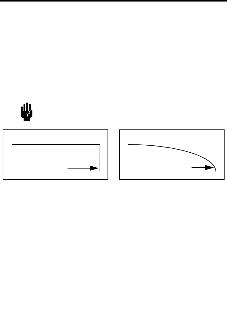
This go/no-go situation is diagrammed in Figure1.
Figure 1Reception Distances for DSS and Analog Transmission
With an Analog Signal, the quality of reception shown in the right side of
Figure1 gradually drops off as you move further away from the transmitting
point or when the transmitter and receiver antennas are not pointed at each
other.
As the left side of Figure1 shows, a Digital Signal provides perfect reception
until a threshold is reached, and then audio is totally lost. The DTC-900-KT
RX has signal strength LEDs on its front panel as well as an audible alarm
that must be monitored to keep you within listening range and direction.
Remember: Watch the green, yellow and red string of LEDs, and do not
disable the audible tone except when security so requires. When the LEDs
drop into the yellow zone, you may lose audio at any time. Close the range to
the agent.
Audio Signal Level
Range for DSS Signal
Audio Signal Level
Range for Analog Signal
4DTC Communications, Inc.
User’s Manual March 1999
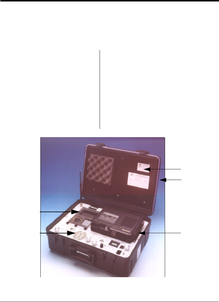
Kit Components
The system is packaged in a rugged carrying case (Figure2) and in a fabric
accessory pouch mounted on the outside of the case cover.
Figure 2Principal Components in the Carrying Case
COMPONENTS IN THE BASE COMPONENTS IN THE ACCESSORY POUCH
1. RX panel
2. TX and components:
AAA alkaline batteries, qty. 5
External microphone
3. Frequency-Channel No. label
4. Cover-mounted accessory
pouch
5. Marantz tape recorder
•RX patch antenna with Mafer
universal clamp
•Cable for RX patch antenna
•Magnetic mount RX antenna
•Stereo headset
•AC and DC power cables
•Marantz recorder manual and this
User’s Manual
8,9
2
1
4
3
6
5
7
4
(pouch on
top of cover)
5
3
1
2
Using the Receiver
DSS-900-KT Digital Spread Spectrum Surveillance System 5
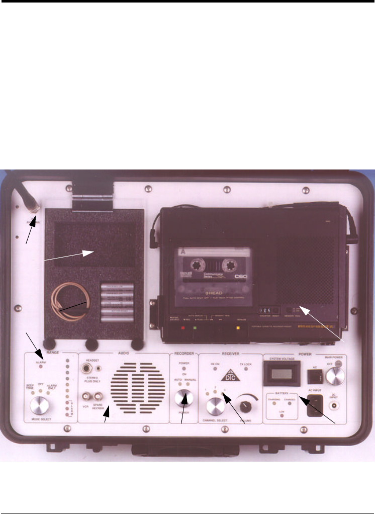
Using the Receiver
Receiver Controls
The main panel within the case of the DSS-900-KT is divided into eight
segments as called out in the photograph of Figure3.
Figure 3Main Panel of the DSS-900-KT
1. Power segment 5. Range/Alarm segment
2. Receiver segment 6. TX, microphone and batteries
3. Recorder segment 7. RX Antenna connector
4. Audio segment 8. Marantz tape recorder
4 3 2
7
5
6
1
8
6DTC Communications, Inc.
User’s Manual March 1999
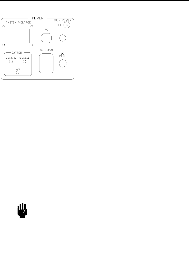
•The SYSTEM VOLTAGE LCD shows you the DC voltage available to the
electronics in the DSS-900-KT. The acceptable range for this display is
11 to 14 VDC. If the external source or battery voltages drop below
11 VDC, the equipment operation will be compromised.
•Whenever the unit is plugged into an active AC or DC source, the
internal batteries are being charged.
•The three LEDs in the BATTERY section of the power segment tell you
the charge status of the internal RX Battery.
CHARGINGIlluminates only if either AC or DC power is being
supplied to the system and the batteries are being
charged. The batteries are always on charge when
there is external power available.
CHARGEDThe internal batteries are fully charged.
LOWThe internal batteries need to be charged.
CAUTION1. When the LOW light comes on, locate a new power
source immediately. The batteries will only power the
RX for 1/2-hour, even when fully charged, and you can
lose contact with the agent without further warning.
2. The DSS-900-KT is designed for AC or DC
operation. The internal batteries are for temporary
emergency use only.
1.Power
•The main power OFF and ON switch
controls power to all RX subsystems
including the Marantz tape recorder. The
recorder must be activated as shown in the
accompanying Marantz operator manual.
•The AC INPUT power receptacle is located
in the lower center. An external DC voltage
source (11 to 16VDC) can be introduced
tothe system at the DC INPUT jack with the
regulated cigarette power adaptor cord.
This adaptor is fused for5A.
Using the Receiver
DSS-900-KT Digital Spread Spectrum Surveillance System 7
•VOLUME sets the volume of the front panel speaker or of the headset if
plugged in. Remember, if a headset is plugged into either jack in the
AUDIO section of the front panel, the speaker is automatically disabled.
You may use both headset jacks.
CAUTIONBe sure that the receiver is set to the channel number
matching the frequency of the TX.
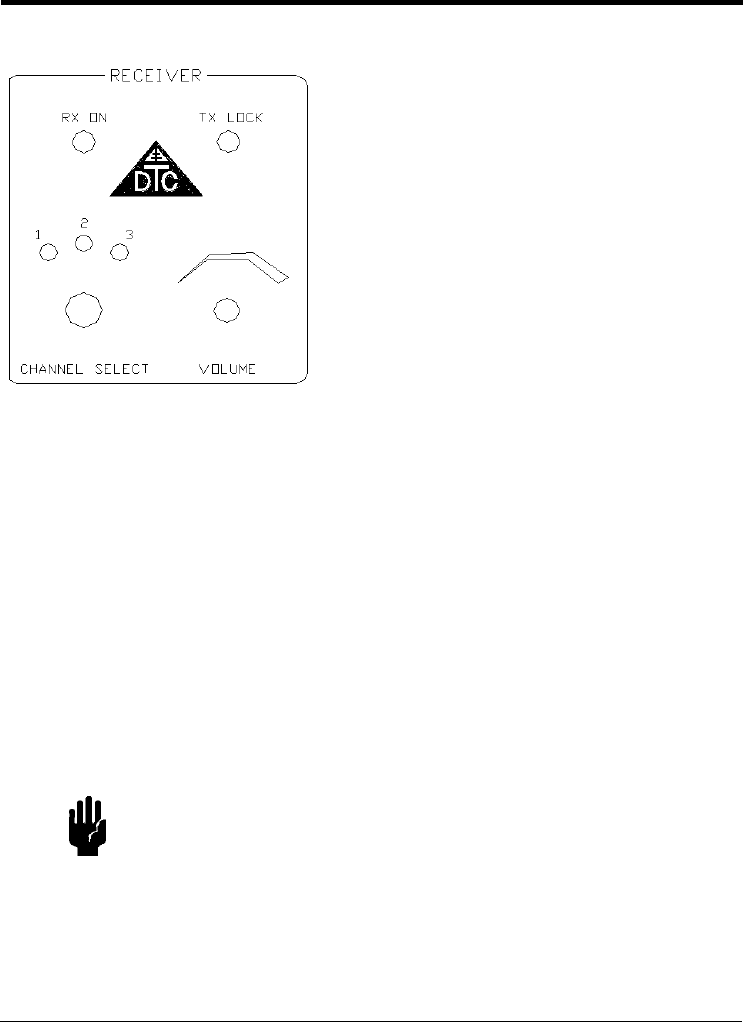
2.Receiver
The RECEIVER section on the front panel
contains two LEDs and two controls.
•RX ON LED tells you that power is applied
to the RX and that the tape recorder
power is enabled. It does not mean that
the RX is necessarily receiving a signal
from the TX,
•TX LOCK LED tells you that the RX is
receiving a signal from the TX and that
the signal is of sufficient strength to be
locked on.
•CHANNEL SELECT enables you to switch
the RX to the frequency printed on the TX
in use. Use the label on the inside of the
top cover of the case to convert TX
frequency to CHANNEL SELECT number.
If the RX is on and set to the correct
channel, and if the TX is on and supplying
a strong signal, the TX LOCK LED will be
lighted. Unless otherwise requested at
the time of purchase, the TXstandard
factory setting is Channel 2.
8DTC Communications, Inc.
User’s Manual March 1999
Drawings and photos of the Marantz tape recorder as well as complete
operating instructions are given in the Marantz operator manual that
accompanies your DSS-900-KT system. The manual is stored in the
accessory pouch of the DSS-900-KT.
Whenever loading a tape into the Marantz recorder, make sure that:
•The tape is fully rewound.
•You are not about to overwrite an existing recording.
•The tape is not write protected.
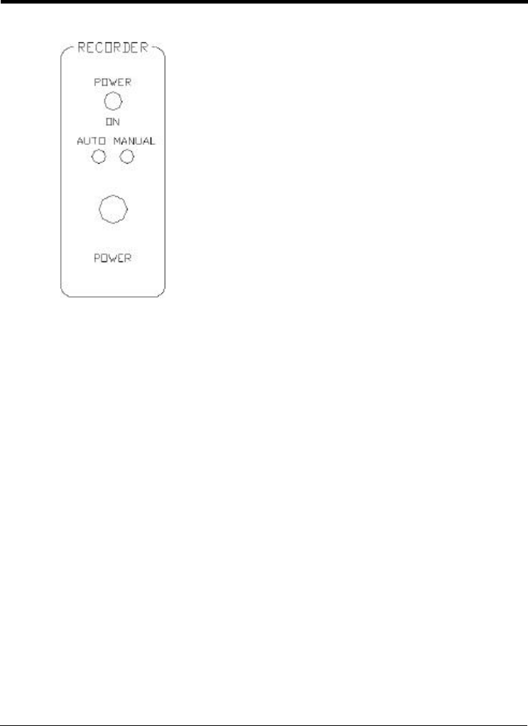
3.Recorder
The RECORDER section contains a single LED
and single switch, both of which relate to the
Marantz tape recorder built into your DSS-
900-KT.
•POWER ON lights up when the POWER
switch located below it is in MANUAL or
when the audio level is above squelch
and the AUTO mode has enabled the
recorder power.
•In the AUTO mode [carrier activation mode
in surveillance terms], the Marantz will
activate if the audio signal rises above the
squelch level set on the recorder front
panel. For this to happen, the TX and RX
have to be locked together on the TX
signal, and the Marantz tape recorder has
to be set to RECORD.
•In the MANUAL mode, the recorder is
always powered up and will run if so
commanded from its front panel.
Using the Receiver
DSS-900-KT Digital Spread Spectrum Surveillance System 9
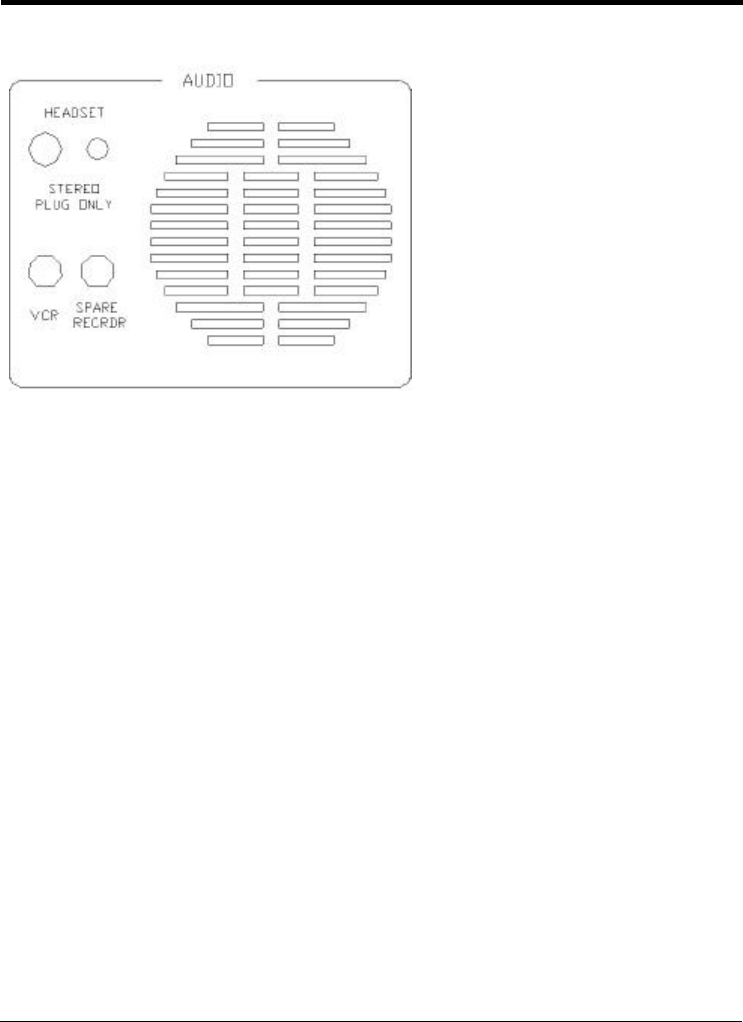
•Two audio signal output connectors.
On the left, VCR, a fixed signal level compatible with a standard VCR.
On the right, SPARE RECRDR, an identical output for a second, spare
recorder.
With these extra connectors, you can make two original audio recordings in
addition to the recording of the Marantz tape deck.
4.Audio
The AUDIO section has five
outputs:
•A speaker set behind the
grillwork.
•Two HEADSET jacks.
On the left, a jack for a
1/4 inch connector.
On the right, a jack for the
3.5 mm mini-jack Sony
headset that is supplied with
your DSS-900-KT.
10 DTC Communications, Inc.
User’s Manual March 1999
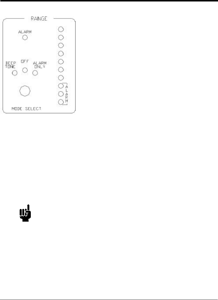
Let’s start at the top of the RANGE section.
ALARM turns on whenever the signal is very low or when you have lost TX lock
on the signal. This forces you to recognize that signal is about to be or has
been lost and you must take action to maintain or restore the audio link.
The MODE SELECT switch has 3 positions.
BEEP TONE during which a continuous beeping takes place; the higher the
tone’s pitch the closer the range.
The beep sound is not recorded on the tape recorder, nor is any indication of
the signal level status recorded.
NOTEThe beep tone can only be stopped by switching to
OFF or to ALARM ONLY settings.
ALARM ONLY produces a continuous tone to warn that an out-of-range situation
is likely to or has occurred.
5.Range
The RANGE section is the one you have to
watchmost closely.
The RANGE LEDs warn you that the DSS signal
is getting low and audio will be lost unless you
reorient the agent or move the RX closer to the
agent.
Remember, with digital spread spectrum, there
is no in-between zone.
Audio is present and perfect, or it’s gone!

Using the Receiver
DSS-900-KT Digital Spread Spectrum Surveillance System 11
Ten LEDs on the right tell you the status of the signal received from the TX.
•Green LEDs - Top 4 greens only come on when the signal is strong and
the TX and RX are locked together. Whenever the Green LEDs are on,
both the yellow and red LEDs below are also on.
•Yellow LEDs - Middle 3 yellows are on with the red LEDs. When the
green LEDs flicker off and the yellow are still on, the signal level is
getting low and a TX lock is in jeopardy.
CAUTIONClose range to the agent immediately! If using the
directional patch antenna, reorient the front of the
antenna so the maximum number of LEDs are on.
•Red LEDs - Lowest 3; when only they are on, you have lost the TX
signal or are very close to losing it. If yellow and green are off, the ALARM
LED is triggered and stays on.
6.Transmitter, microphone and batteries
Refer to Using the Transmitter on page13 for details.
12 DTC Communications, Inc.
User’s Manual March 1999
7.RX Antenna Connector
Both the 3 dBi omni-directional magnetic mount antenna (Figure2 on page 4)
and the 11 dBi high gain patch antenna are attached at the RX ANTENNA BNC
connector.
Use the patch antenna with the Mafer clamp whenever you can reasonably
expect the wired agentto be within a known general location, such as a
particular street corner.The patch antenna is quite directional with a beam
width of about 60°. With thepatch antenna you will receive at a greater
distance than with the omni-directional magnetic mount.
When using the patch, orient it with the Plexiglas side facing toward the
expected location of the transmitting bodywire.
CAUTIONPatch antennas are directional. Always orient the
RXpatch toward the TX. On a surveillance mission,
the agent should take care, within bounds of security
and safety, to be oriented with the TX patch antenna
outwards from the agent’s body and facing the RX.
TIPMount the RX patch antenna as high as possible to
provide a better unobstructed path to the TX.
8.Marantz Tape Recorder
For detailed information, refer to the Marantz operator manual that is
contained in the accessory pouch mounted on the top of the DSS-900-KT
case cover.
Using the Transmitter
DSS-900-KT Digital Spread Spectrum Surveillance System 13
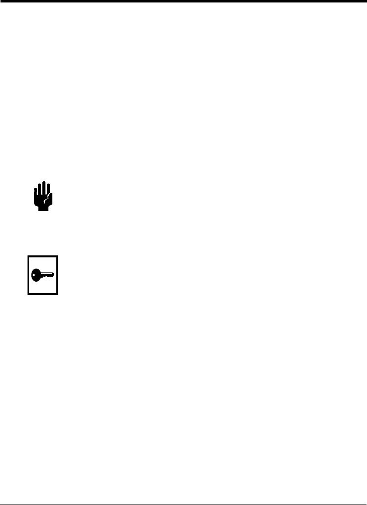
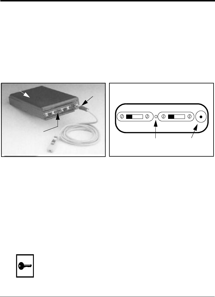
Using the Transmitter
Keep in mind that the TX patch antenna must be facing away from the
agent’s body to work properly. The patch antenna is housed in the black
plastic-like dome on the TX unit. There is no external antenna on this unit.
•The internal top fire mike is located between the two slide switches
(Figure4-b). It is active unless an external mike is plugged into the gold
Lemo connector as shown in Figure4-a. Two microphones are supplied
with the DSS-900-KT; they differ only in color and cable length.
Figure 4a. TX with External Microphone b. TX Panel
1. Start the surveillance session with fresh TX batteries. Slide the battery
holder cover open to insert batteries (Figure3 on page 5).
2. The TX unit is labelled with its frequency. Use the label on the inside
of the DSS-900-KT case cover (see Figure2 on page 4) to determine
the channel number corresponding to the TX frequency.
3. Set CHANNEL SELECT on the RECEIVER to the same number.
4. Turn the TX ON using the slide switch at the top of the unit.
5. Set the AGC ON. This provides optimum audio at the RX. Set the AGC
OFF if a loud, interfering noise, such as a jukebox, is near the agent.
TIPRemind the agent wearing the wire to face toward the
RX whenever possible during the mission to produce
the strongest signal at the RX.
a
l
Antenna
Power AGC
On Off On Off
Internal External
bMicrophoneMicrophone
Internal
Microphone
External
Microphone
External
Microphone
a
Internal
Microphone
Antenna

14 DTC Communications, Inc.
User’s Manual March 1999
Field Use of the DSS-900-KT
Each control on the RX is explained in Receiver Controls starting on page 5
and is shown in Figure3, also on page 5. The TX and its setup are described
in Using the Transmitter on page13. The Quickstart: DSS-900-KT
Surveillance System on page1 contains an information overview on field use.
1. Verify that the transmitter is switched on.
2. Connect either the DC INPUT or AC INPUT to the appropriate power
source.
•The SYSTEM VOLTAGE will rise to about 14 VDC. It must not be
outside the range of 11 to 16 VDC.
•The RX ON LED will illuminate.
•The CHARGING LED will turn on and stay on as long as there is
power at either power input.
•If LOW turns on, the internal battery is discharged and you must
find an alternate power source. Do not begin a mission. The
battery will fully charge in 4 hours.
CAUTIONThe DSS-900-KT is designed for AC or DC operation.
The internal batteries in the RX are for temporary
emergency use only.
3. Check that a receiving antenna, either the patch or the mag mount,
isconnected at the RX ANTENNA BNC jack on the RX panel.
4. If you intend to use a headset for monitoring, plug in one or two
headsets now. The speaker will be disabled.
•Use only stereo headsets at these jacks.
5. If you want to make additional original recordings of the mission,
plugthe extra recorders into the VCR and SPARE RECRDR jacks.

Field Use of the DSS-900-KT
DSS-900-KT Digital Spread Spectrum Surveillance System 15
6. If the TX has not yet been deployed, check its channel number and
switch CHANNEL SELECT on the RX to that number.
•If the TX is already harnessed to the agent, move the CHANNEL
SELECT switch until you see the TX LOCK light turn on. This
indicates that the agent has activated the TX and you are
receiving audio.
7. Adjust the VOLUME control, which affects the speaker and the
headsets only. It does not affect the recording.
8. Set the recorder to AUTO unless you specifically do not want
automatic on/off of the tape.
•The POWER ON LED in the RECORDER SECTION will light up when
the squelch level is exceeded by the audio, or whenever you
switch to MANUAL.
9. In the RANGE section, switch MODE SELECT to the alarm output you
want. Refer back to Range on page10 to remind yourself what this
switch does.
10. Verify that TX LOCK is illuminated on the RECEIVER section of the RX.
If this LED is not on, take the following steps.
•Make sure you are using fresh batteries in the TX.
•Make sure that TX and RX are on the same channel.
•Close range to the agent.
•Reorient the RX patch antenna so it is directed more accurately
toward the agent. This antenna has a 60o beam width, so if the
agent is outside that cone, you are losing a great deal of the
available signal.
•Double-check that the RX is turned on, system voltage is in the
acceptable range, and that all connections are secure.