DTC Communications MBOX4DS Licensed non broadcast 1Watt COFDM video transmitter User Manual Manual Part 1
DTC Communications Inc. Licensed non broadcast 1Watt COFDM video transmitter Manual Part 1
Contents
- 1. Manual Statements
- 2. Manual Part 1
- 3. Manual Part 2
- 4. Manual Part 3
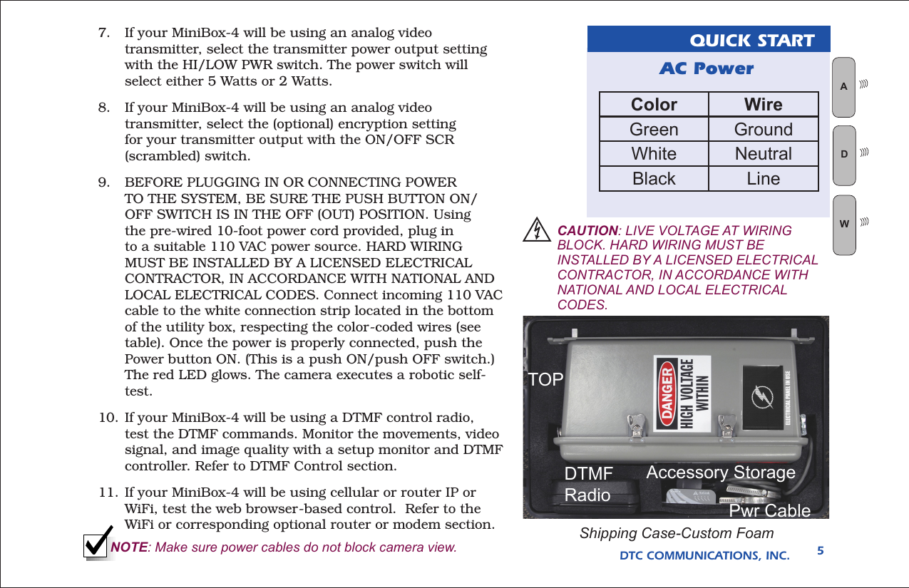
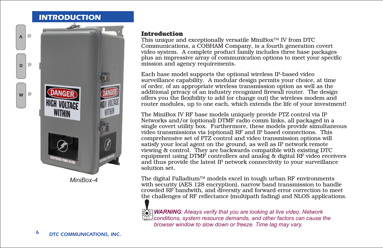
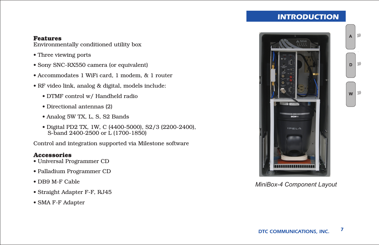
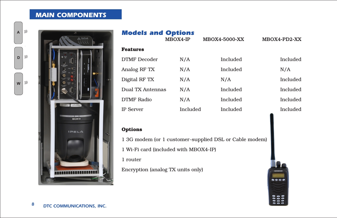
Manual Part 1