DTC Communications MBOX4DS Licensed non broadcast 1Watt COFDM video transmitter User Manual Manual Part 1
DTC Communications Inc. Licensed non broadcast 1Watt COFDM video transmitter Manual Part 1
Contents
- 1. Manual Statements
- 2. Manual Part 1
- 3. Manual Part 2
- 4. Manual Part 3
Manual Part 1
MiniBox IV
IP Video Transmitter
• Model MBOX4-IP with WiFi
• Model MBOX4-5000-XX with 5W Analog TX and DTMF Control Radio
• Model MBOX-PD2-XX with 1W Digital TX and DTMF Control Radio
--Options include WiFi, Cellular Modem, VPN Router

DTC COMMUNICATIONS, INC.
2PN OP1920487 Rev. F
copyright notice
Copyright © 2008
DTC Communications, Inc. All rights
reserved. No part of this document may be
reproduced, transmitted, transcribed, stored
in a retrieval system or translated into any
language or computer language, in any form
or by any means, including but not limited
to electronic, magnetic, mechanical, optical,
chemical, manual or otherwise, without the
prior written permission of DTC
Communications, Inc.
disclaimer
The information in the document is subject
to change without notice. DTC makes no
representations or warranties with respect to
the contents hereof, and specifically disclaims
any implied warranties of merchantability or
fitness for a particular purpose. DTC reserves
the right to revise this publication and to
make changes from time to time in the con-
tent hereof without obligation of DTC to notify
any person of such revision or changes.
how to contact DTC
For operator and troubleshooting informa-
tion, customers are encouraged to refer to the
details in this manual. For additional
clarification or instruction, or to order parts,
contact DTC.
Customer Service is available Monday through
Friday between the hours of 9:00 AM and
5:00 PM EST at:
Tel: 603-880-4411
Fax: 603-880-6965
Website: www.dtccom.com
Email: info@dtccom.com
486 Amherst Street
Nashua, New Hampshire 03063
trademarks
Trademarks of DTC Communications, Inc.
include:
• DTCTM
• PalladiumTM
• ArmorNetTM
• SplitPIXTM
• MiniPIXTM
• DynaViewTM
Other product names used in this manual are
the properties of their respective owners.

DTC COMMUNICATIONS, INC. 3
A
W
D
ANALOG for users of
Model MBOX4-5000-XX with
5W Analog TX
NOTE Describes special issues
you should be aware of while
using a particular function.
WARNING Calls out situations
in which equipment could be
damaged or a process could be
incorrectly implemented, but in
which operator safety is not a
factor.
TIP Describes application hints.
CAUTION Electric shock hazard.
Personal injury may result.
Only trained and experienced
technicians should proceed.
manual conventions
QUICK START .....................................................................................................4-5
INTRODUCTION .....................................................................................................6-7
MAIN COMPONENTS .............................................................................................8-9
MODELS AND OPTIONS ...............................................................8
CONTROL, VIDEO, POWER .........................................................9
INSTALLATION .................................................................................................10-11
SITE SURVEY ..............................................................................10
ANTENNA OPTIONS .................................................................... 11
WALL MOUNTING SCHEME .......................................................12
POLE MOUNTING SCHEME .......................................................13
Wi-Fi SETUP ...............................................................................................14-15
OPERATION .................................................................................................16-30
AC POWER INPUT
MINIBOX CONTROL PANEL ...................................................................16-17
CONCEALED CAMERA PORTS, VENTILATION, AND THERMAL ............18
SONY IP CAMERA & PTZ, TRANSMITTERS ..............................................19
WI-FI SETUP/OPERATION .....................................................................20-21
DTMF CONTROL.....................................................................................22-30
DTMF PORTABLE RADIO............................................................22
DTMF MENUS ..............................................................................24
INSTALLING A CUSTOMER-SUPPLIED OPTION .......................................31
OPTIONAL WIRELESS CELLULAR MODEM .........................................32-33
ACTIVATING ON YOUR CELLULAR NETWORK ........................33
OPTIONAL VPN ROUTER ......................................................................34-35
DIGITAL-ANALOG TX AND DTMF RX PROGRAMMING ...................................36-37
SPECIFICATIONS ....................................................................................................38
CONTACT US ......................................................................................................39
TABLE OF CONTENTS
Wi-Fi for users of
Model with MBOX4-IP with WiFi
DIGITAL for users of
Model MBOX4-PD2-XX with 1W
Digital TX
DTC COMMUNICATIONS, INC.
4
A
W
D
Complete the following steps:
1. Unpack the components from the shipping container.
2. Mount the utility box in a temporary (service bench) location using
one of the methods described in the Installation section.
3. Disengage the support bracket (see warning).
4. If your MiniBox-4 will be using a digital or analog video transmitter
connect both transmitting antennas to maximize the coverage
pattern or use one antenna to maximize gain in one direction only.
To use both antennas, connect the splitter; to use one antenna, use
the double-female adapter. (Factory-set to both antennas.)
5. If your MiniBox-4 will be using a digital or analog video transmitter,
set the channel selector in the VIDEO TX section of the control
panel to the desired frequency for your Video Transmitter.
6. If your MiniBox-4 will be using a DTMF control radio, set the
channel selector in the DTMF RX section of the control panel to the
same frequency as being used by your radio. The MiniBox-4 lists
both DTMF and Transmitter pre-programmed frequencies on the
Quick Start Card located on the inside of the door.
QUICK START
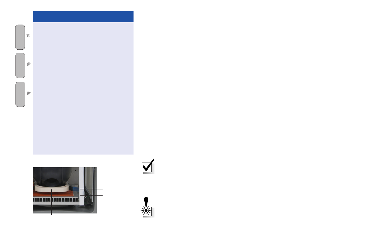
WARNING
Avoid permanent damage to the
camera!
• Disengage the support bracket
(down position) before turning the
system ON.
• Engage the support bracket
(up position) before moving or
shipping the system.
To Disengage the support
bracket: pull spring tabs out and
move bracket down one position.
To Engage the support bracket:
pull spring tabs out and move
bracket up to highest position.
Engage
Disengage
Support Bracket
NOTE: The MiniBox-4 offers three viewing windows; front and two sides. You
may choose to use one or all three. The unit is shipped with a Velcro® curtain
covering the front window and inserts that block the side windows. Remove
the curtain and/or inserts from the window(s) you plan to use. Always keep
unused windows blocked when not in use to prevent light from entering the
enclosure.
WARNING: Drop and shock sensitive equipment. Avoid permanent damage
to your system. Do not ship this product without proper packaging. This unit
must be boxed and protected with packaging materials before shipping.
DTC COMMUNICATIONS, INC. 5
A
W
D
7. If your MiniBox-4 will be using an analog video
transmitter, select the transmitter power output setting
with the HI/LOW PWR switch. The power switch will
select either 5 Watts or 2 Watts.
8. If your MiniBox-4 will be using an analog video
transmitter, select the (optional) encryption setting
for your transmitter output with the ON/OFF SCR
(scrambled) switch.
9. BEFORE PLUGGING IN OR CONNECTING POWER
TO THE SYSTEM, BE SURE THE PUSH BUTTON ON/
OFF SWITCH IS IN THE OFF (OUT) POSITION. Using
the pre-wired 10-foot power cord provided, plug in
to a suitable 110 VAC power source. HARD WIRING
MUST BE INSTALLED BY A LICENSED ELECTRICAL
CONTRACTOR, IN ACCORDANCE WITH NATIONAL AND
LOCAL ELECTRICAL CODES. Connect incoming 110 VAC
cable to the white connection strip located in the bottom
of the utility box, respecting the color-coded wires (see
table). Once the power is properly connected, push the
Power button ON. (This is a push ON/push OFF switch.)
The red LED glows. The camera executes a robotic self-
test.
10. If your MiniBox-4 will be using a DTMF control radio,
test the DTMF commands. Monitor the movements, video
signal, and image quality with a setup monitor and DTMF
controller. Refer to DTMF Control section.
11. If your MiniBox-4 will be using cellular or router IP or
WiFi, test the web browser-based control. Refer to the
WiFi or corresponding optional router or modem section.
QUICK START
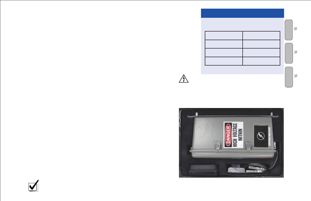
Color Wire
Green Ground
White Neutral
Black Line
AC Power
Shipping Case-Custom Foam
NOTE: Make sure power cables do not block camera view.
TOP
Pwr Cable
Accessory Storage
DTMF
Radio
CAUTION: LIVE VOLTAGE AT WIRING
BLOCK. HARD WIRING MUST BE
INSTALLED BY A LICENSED ELECTRICAL
CONTRACTOR, IN ACCORDANCE WITH
NATIONAL AND LOCAL ELECTRICAL
CODES.
DTC COMMUNICATIONS, INC.
6
INTRODUCTION
MiniBox-4
Introduction
This unique and exceptionally versatile MiniBox™ IV from DTC
Communications, a COBHAM Company, is a fourth generation covert
video system. A complete product family includes three base packages
plus an impressive array of communication options to meet your specific
mission and agency requirements.
Each base model supports the optional wireless IP-based video
surveillance capability. A modular design permits your choice, at time
of order, of an appropriate wireless transmission option as well as the
additional privacy of an industry recognized firewall router. The design
offers you the flexibility to add (or change out) the wireless modem and
router modules, up to one each, which extends the life of your investment!
The MiniBox IV RF base models uniquely provide PTZ control via IP
Networks and/or (optional) DTMF radio comm links, all packaged in a
single covert utility box. Furthermore, these models provide simultaneous
video transmissions via (optional) RF and IP based connections. This
comprehensive set of PTZ control and video transmission options will
satisfy your local agent on the ground, as well as IP network remote
viewing & control. They are backwards compatible with existing DTC
equipment using DTMF controllers and analog & digital RF video receivers
and thus provide the latest IP network connectivity to your surveillance
solution set.
The digital Palladium™ models excel in tough urban RF environments
with security (AES 128 encryption), narrow band transmission to handle
crowded RF bandwith, and diversity and forward error correction to meet
the challenges of RF reflectance (multipath fading) and NLOS applications.
WARNING: Always verify that you are looking at live video. Network
conditions, system resource demands, and other factors can cause the
browser window to slow down or freeze. Time lag may vary.
A
N LOG
W
D

DTC COMMUNICATIONS, INC. 7
INTRODUCTION
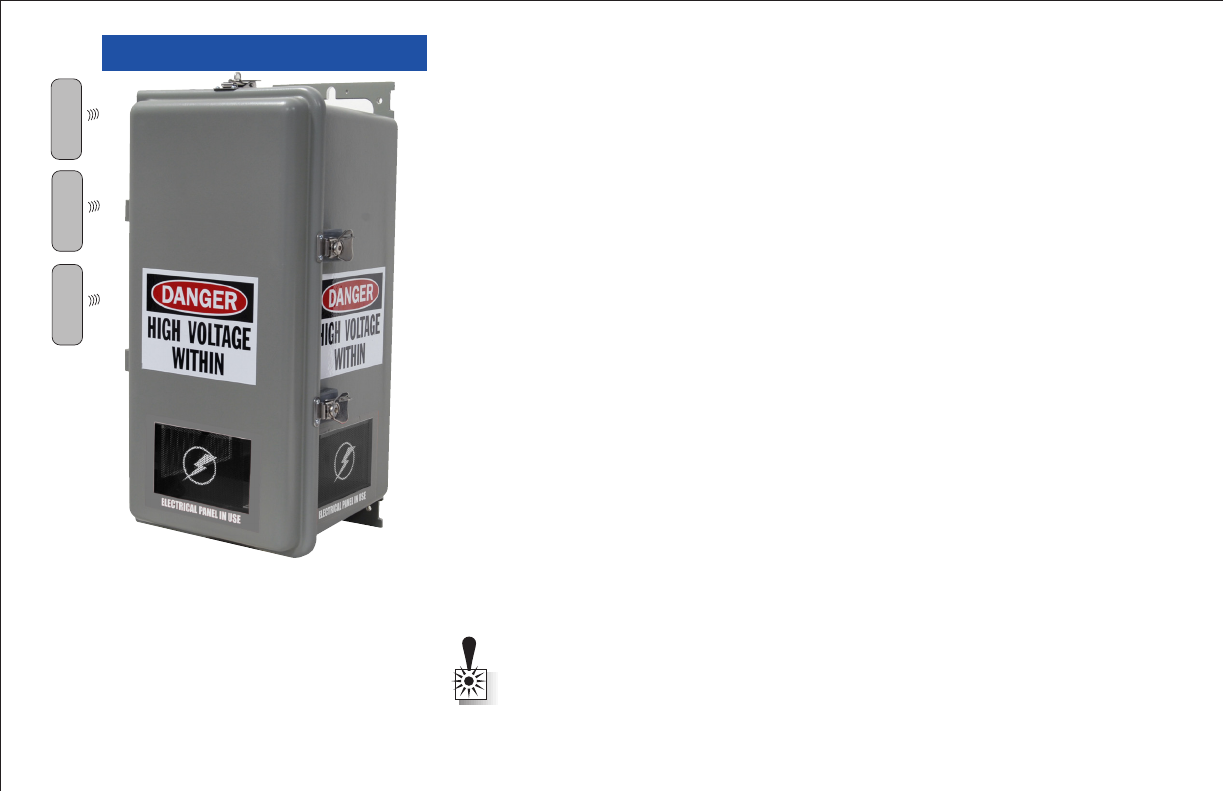
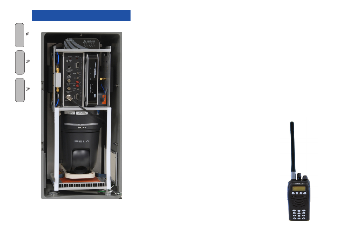
MiniBox-4 Component Layout
Features
Environmentally conditioned utility box
• Three viewing ports
• Sony SNC-RX550 camera (or equivalent)
• Accommodates 1 WiFi card, 1 modem, & 1 router
• RF video link, analog & digital, models include:
• DTMF control w/ Handheld radio
• Directional antennas (2)
• Analog 5W TX, L, S, S2 Bands
• Digital PD2 TX, 1W, C (4400-5000), S2/3 (2200-2400),
S-band 2400-2500 or L (1700-1850)
Control and integration supported via Milestone software
Accessories
• Universal Programmer CD
• Palladium Programmer CD
• DB9 M-F Cable
• Straight Adapter F-F, RJ45
• SMA F-F Adapter
W
A
N LOG
W
D
DTC COMMUNICATIONS, INC.
8
MAIN COMPONENTS
Models and Options
MBOX4-IP MBOX4-5000-XX MBOX4-PD2-XX
Features
DTMF Decoder N/A Included Included
Analog RF TX N/A Included N/A
Digital RF TX N/A N/A Included
Dual TX Antennas N/A Included Included
DTMF Radio N/A Included Included
IP Server Included Included Included
Options
1 3G modem (or 1 customer-supplied DSL or Cable modem)
1 Wi-Fi card (included with MBOX4-IP)
1 router
Encryption (analog TX units only)
A
N LOG
W
D

DTC COMMUNICATIONS, INC. 9
MAIN COMPONENTS
Control
DTMF tones can be used to pan and tilt the camera
(transmitter units only), and to actuate many camera
functions. DTC’s low current R99WS control receiver
has been integrated into the transmitter models for use
with a two-way radio, included with the system.
VPN and WiFi units are controlled via an internet web
browser user interface. The browser-based controls are
described in this manual.
Video
Analog video transmission is accomplished by DTC’s
2 Watt/5 Watt VMX series video transmitter. These
transmitters feature ten user programmable channels,
an efficient switching power supply, and low heat
generation.
Digital video transmission is accomplished by DTC’s
Palladium video transmitter with an output power of
1 Watt. These transmitters feature COFDM and digital
encryption for secure signals in non-line-of-sight
environments.
IP video is viewed as either JPEG video or MPEG-4,
depending on user selection.
Power
The MiniBox-4 operates on 110 VAC power. A power
cord and a wiring block (for hard-wiring) has been
provided.
Power Considerations
The MiniBox-4 can be powered by
any standard 110 VAC, 15 amp
branch circuit.
The AC Power Reset provides
overcurrent protection for the
Minibox-4 system.
The AC Breaker Reset provides
overcurrent protection for all
accessories plugged-into the
outlets provided inside the
MiniBox-4.
Five amps is the total current
allowed for all accessories
plugged-into the four outlets.
W
A
N LOG
W
A
NALO
D
BEFORE PLUGGING IN OR CONNECTING
POWER TO THE SYSTEM, BE SURE THE
PUSH BUTTON ON/OFF SWITCH IS IN THE
OFF (OUT) POSITION. HARD WIRING MUST
BE INSTALLED BY A LICENSED ELECTRICAL
CONTRACTOR, IN ACCORDANCE WITH
NATIONAL AND LOCAL ELECTRICAL CODES.
DTC COMMUNICATIONS, INC.
10
INSTALLATION
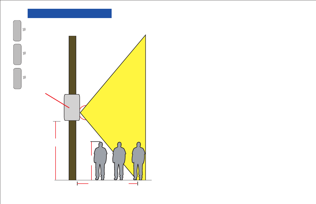
Site Survey
Before installing the MiniBox-4, you should conduct
a physical survey of the site where the unit is to be
installed. The purpose of the survey is to determine
the proper height and position of the unit relative to
the primary subject to be observed. You should also
consider 110 VAC power availability (and cable or DSL
availability if applicable).
Determining the optimum position for the MiniBox-
4 involves several considerations including the focal
length of the lens, the upper and lower limits of travel,
and the distance between the mounting site and the
object under surveillance.
For rule-of-thumb purposes, you might think of the
viewable area this way for a reasonable approximation:
At 10 feet high the blind spot on the ground will be
approximately 10 feet inward and the viewable width
will be approximately 10 feet out. At 20 feet high the
blind spot on the ground will be approximately 20 feet
inward and the viewable width will be approximately 20
feet out.
Items outside of the Utility Box’s viewable limits will
not be visible. See the example at left. A subject close to
the bottom of the pole would not be visible to the Utility
Box. You should set-up and test the Utility Box at an
alternate site but under similar conditions in advance
of your mission. This is the best way to ensure that you
will know what to expect once you have deployed the
Utility Box at the actual surveillance site.
Viewable Area
MiniBox-4
Front
10 ft.
6 ft.
Approx. 10 ft.
A
N LOG
W
A
D