DTC Communications MBOX4DS Licensed non broadcast 1Watt COFDM video transmitter User Manual Manual Part 2
DTC Communications Inc. Licensed non broadcast 1Watt COFDM video transmitter Manual Part 2
Contents
- 1. Manual Statements
- 2. Manual Part 1
- 3. Manual Part 2
- 4. Manual Part 3
Manual Part 2
DTC COMMUNICATIONS, INC. 11
INSTALLATION
Antenna Options
Before installing the MiniBox-4, you should also
consider antenna options (if you are using RF analog or
digital transmission). You have the choice of using one
or two patch antennas.
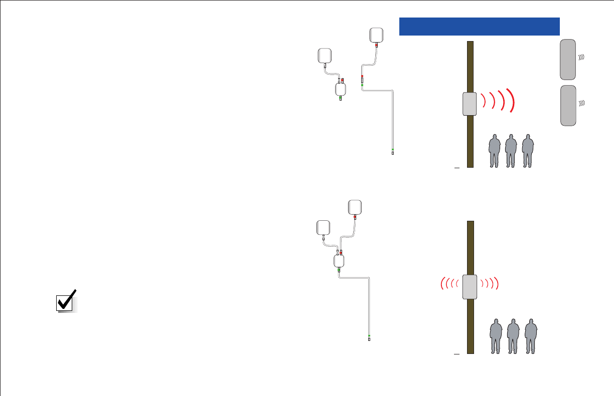
Using both patch antennas with the supplied splitter
will provide the largest radiation pattern but at a
lower gain. Using one antenna will make the radiation
pattern directional, but will typically double the gain,
which will increase the signal range in that direction.
To configure for one antenna, disconnect the coax
from the transmitter at the bottom of the splitter and
connect the double-female adapter in its place. Connect
the cable from the desired active antenna to the
adapter. See illustration top right.
To configure for two antennas, disconnect the coax
from the transmitter at the double-female adapter and
connect the splitter (input) in its place. Connect the
cables from both antennas to the splitter (outputs). See
illustration bottom right.
NOTE: Do NOT remove antenna connections
with device powered ON!
MiniBox-4 Using
2 Patch Antennas
MiniBox-4 Using
1 Patch Antenna
SPLITTER
RIGHT PATCH
ANTENNA
LEFT
PATCH
ANTENNA
TRANSMITTE
R
SPLITTER
DOUBLE FEMALE
ADAPTER
ACTIVE PATCH
ANTENNA
NON ACTIVE
PATCH
ANTENNA
TRANSMITTER
One Antenna Conguration
Two Antenna Conguration
W
A
N LOG
D
DTC COMMUNICATIONS, INC.
12
WALL MOUNTING SCHEME
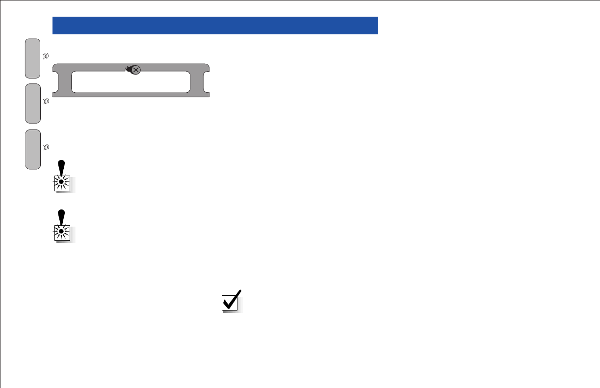
Wall-Mounting the MiniBox-4
To wall-mount the MiniBox-4, complete the following steps:
1. Dry-fit the MiniBox on the wall and make a pencil mark on the wall at
the top-center mounting slot.
2. Drill a pilot hole at the pencil mark for a mounting screw. Make sure
the wall is composed of solid, strong material such as wood or metal,
Select a fastener that will support at least 30 pounds.
3. Install the screw but leave enough of the shank exposed (1-1/4”
minimum) to hang the MiniBox-4 on.
4. Hang the MiniBox-4 as shown (left).
5. With the MiniBox-4 plumb and level, drill and mount a second screw
in the bottom mounting hole.
6. Tighten the top screw.
Top of MiniBox-4
WARNING: To prevent
overheating, make sure the rear
vent is not blocked.
WARNING: Never stand on or
place weight on the MiniBox-4.
A
N LOG
W
D GITAL
D
NOTE: Do NOT overtighten the mounting screws. Tighten enough to snug
the wall mount bracket to the wall. Overtightening may bend or damage the
mounting plate.
DTC COMMUNICATIONS, INC. 13
POLE MOUNTING SCHEME
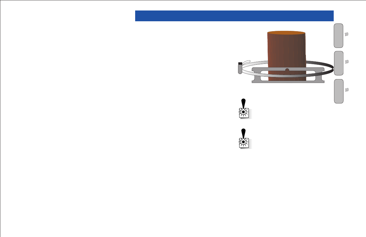
Top of MiniBox-4
Pole-Mounting the MiniBox-4
To pole-mount the MiniBox-4, complete the following steps:
1. Use the Wall Mounting Scheme steps 1-4 (left) to hang the MiniBox-4
on the pole. Alternatively, a helper can hold the MiniBox-4 in place
for step 2 below. The back of the MiniBox-4 features a self-centering
bracket.
2. Using a band-clamp (provided), secure the top of the MiniBox-4 to the
pole as shown (right).
3. Using a band-clamp (provided), secure the bottom of the MiniBox-4 to
the pole in the same fashion.
WARNING: To prevent
overheating, make sure the rear
vent is not blocked.
WARNING: Never stand on or
place weight on the MiniBox-4.
W
A
N LOG
W
D
DTC COMMUNICATIONS, INC.
14
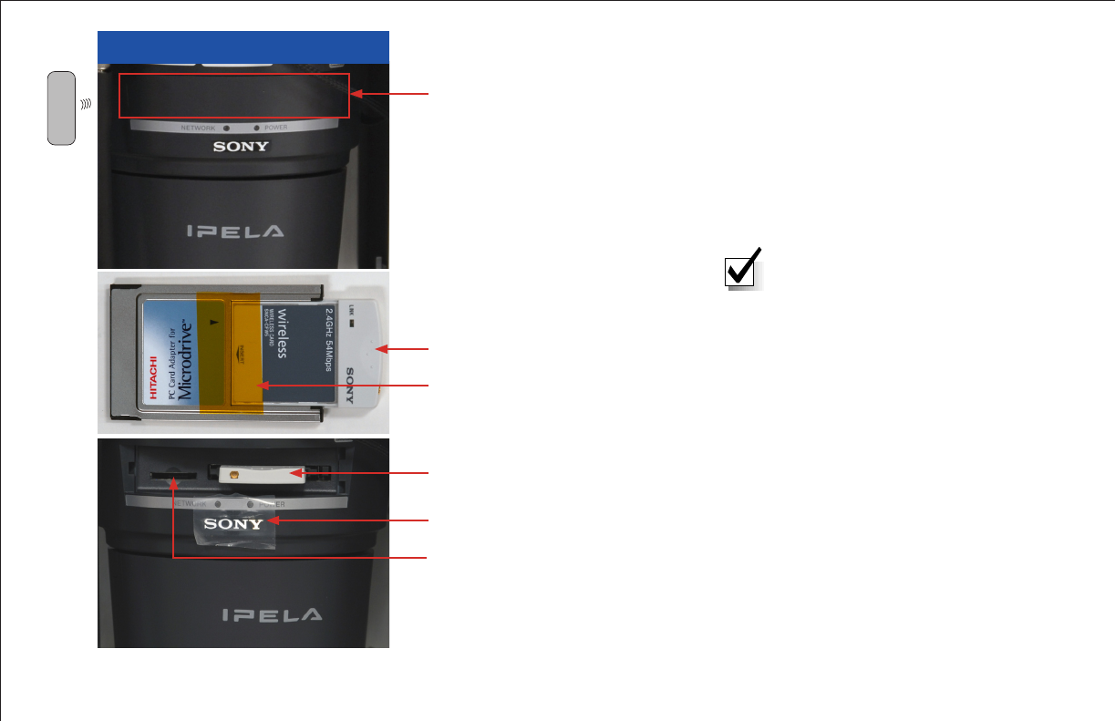
PCMCIA Slot (Gently squeeze
cover to remove)
WI-FI SETUP
Wi-Fi Card in PCMCIA Adapter
Kapton® Tape
Wi-Fi Card in PCMCIA Adapter
Remove Protective Packaging
Memory Stick Slot
Wi-Fi
Factory setting of the camera
network is DHCP.
Wireless LAN settings: Type=adhoc,
SSID=snc-rx550, Channel=11
ch, WEP=nothing, IP address
10.0.0.100, subnet mask=255.0.0.0
W
Tech Tip: Set your conguration
computer for an IP address in
the shipped WiFi family. As an
example, the WiFi is shipped
10.0.0.100, subnet 255.0.0.0. Set
your conguration computer for
10.0.0.101, subnet 255.0.0.0.

DTC COMMUNICATIONS, INC. 15
WI-FI SETUP
WARNING
WiFi (802.11g) operates in the
S-Band 2.4 GHz.
If your MiniBox-4 is equipped
with both WiFi and an S, S2,
S3 Band transmitter, the
transmitter will cause the WiFi
system to be intermittent or
inoperable. Use either WiFi or S,
S2, S3 Band transmitter, but not
both at the same time.
WiFi may also suffer from
interference if used in close
proximity to microwave ovens
and cordless phones.
To setup your Wi-Fi option, complete the following steps:
1. Remove the plastic door from the front of the camera to expose the
PCMCIA slot.
2. The 802.11 Wi-Fi card is shipped in the Accessory Bag--attached
with Kapton tape to the PCMCIA Adapter. Push this assembly gently
but firmly into the slot on the front of the camera as shown. The gold
connector must be on the left.
3. Access the Wi-Fi signal with a Wi-Fi-equipped computer via a web
browser (see page 20).
4. To remove the card and adapter assembly, press the eject button to
the right of the PCMCIA slot.
W
Camera Latency: In applications where continuous or frequent camera
control commands are sent or if controlling the camera using two sources
(RF TX & WiFi) at the same time, latency may build due to the buffering and
processing of these commands. This latency will be observed as the camera
being slow or non-responsive to commands. To minimize this effect, DTC
recommends controlling the camera with one source at a time and lowering
the frame-rate to 5 fps for optimum viewing and operation.
DTC COMMUNICATIONS, INC.
16
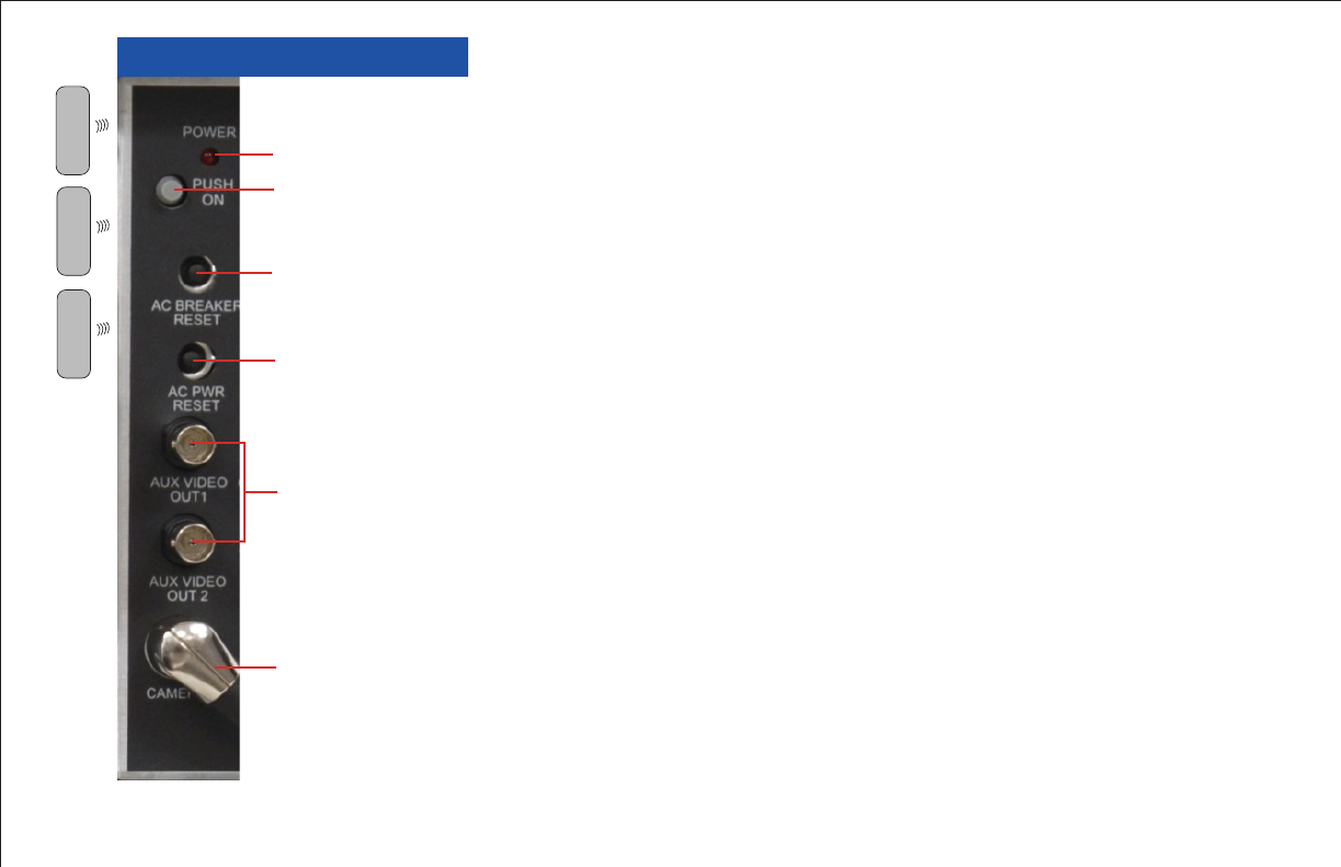
OPERATION Control Panel - All Models
Power LED The Power LED is ON or OFF to indicate that main power to
the MiniBox-4 is ON or OFF. The LED blinks briefly during power-up.
Push ON The Push ON button is a push-push master power ON/OFF
switch for the MiniBox-4 including accessories plugged into the outlets.
Always turn this master power ON/OFF switch to OFF before applying
power or plugging anything into the MiniBox-4 outlets.
AC Breaker Reset The AC Breaker Reset is a 5 Amp circuit breaker that
protects the outlets inside the MiniBox-4.
AC Power Reset The AC Power Reset is a circuit breaker that protects the
MiniBox-4 electronics.
Video Outputs The MiniBox-4 has two video output connectors on the
control panel. These are available for use with customer-supplied test
monitors, VCRs, or DVRs as desired.
Camera Connector The Camera Connector is a multi-I/O connector that
connects to the SONY IPELA camera.
Power LED
Push ON
AC Breaker Reset
AC Power Reset
Video Outputs
Camera Connector
A
N LOG
W
D

DTC COMMUNICATIONS, INC. 17
OPERATION
Control Panel - Transmitter Models Only
Status LED The Status LED is ON or OFF to indicate that the transmitter
is ON or OFF. The Status LED flashes to indicate that the channel
selection was controlled by the DTMF radio, which means the channel
selector switch does not correctly indicate what channel is in use.
TX Programming Connector The digital or analog transmitter
programming connector allows the user to connect to the transmitter’s
programming DB-9 cable connector without having to remove the
transmitter from the MiniBox-4.
PWR High/Low The PWR High/Low switch is used for MiniBox-4 models
with analog transmitter only. The switch selects either high power
(approximately 5 Watts) or low power (approximately 2 Watts).
Sig SCR/CLR The Sig SCR/CLR switch is for MiniBox-4 models with
analog transmitter and optional scrambling only. The switch selects
scrambled or clear transmition.
Chan Sel Video TX The Chan Sel Video TX switch allows the user to select
channels (10 analog or 8 digital) without having to access the transmitter,
which is built inside the MiniBox-4.
Chan Sel DTMF RX The Chan Sel DTMF RX switch allows the user to
select channels on the DTMF receiver. The selected frequency should
correspond with the Kenwood DTMF radio.
Audio Out The audio out connector allows the user to temporarily listen
to a channel with headphones to ensure that it is free of interference from
other transmitters. DO NOT leave headphones connected during normal
operation.
DTMF RX Programming Connector The DTMF RX programming
connector allows the user to connect to the DTMF reveiver’s programming
DB-9 cable connector without having to remove the receiver from the
MiniBox-4.
Status LED
Video TX
Programming
Connector
Video TX PWR
High/Low
Sig SCR/CLR
Video TX
Chan Select
DTMF RX
Chan Select
Audio Out
DTMF RX Prog
Connector
W
A
N LOG
D
DTC COMMUNICATIONS, INC.
18
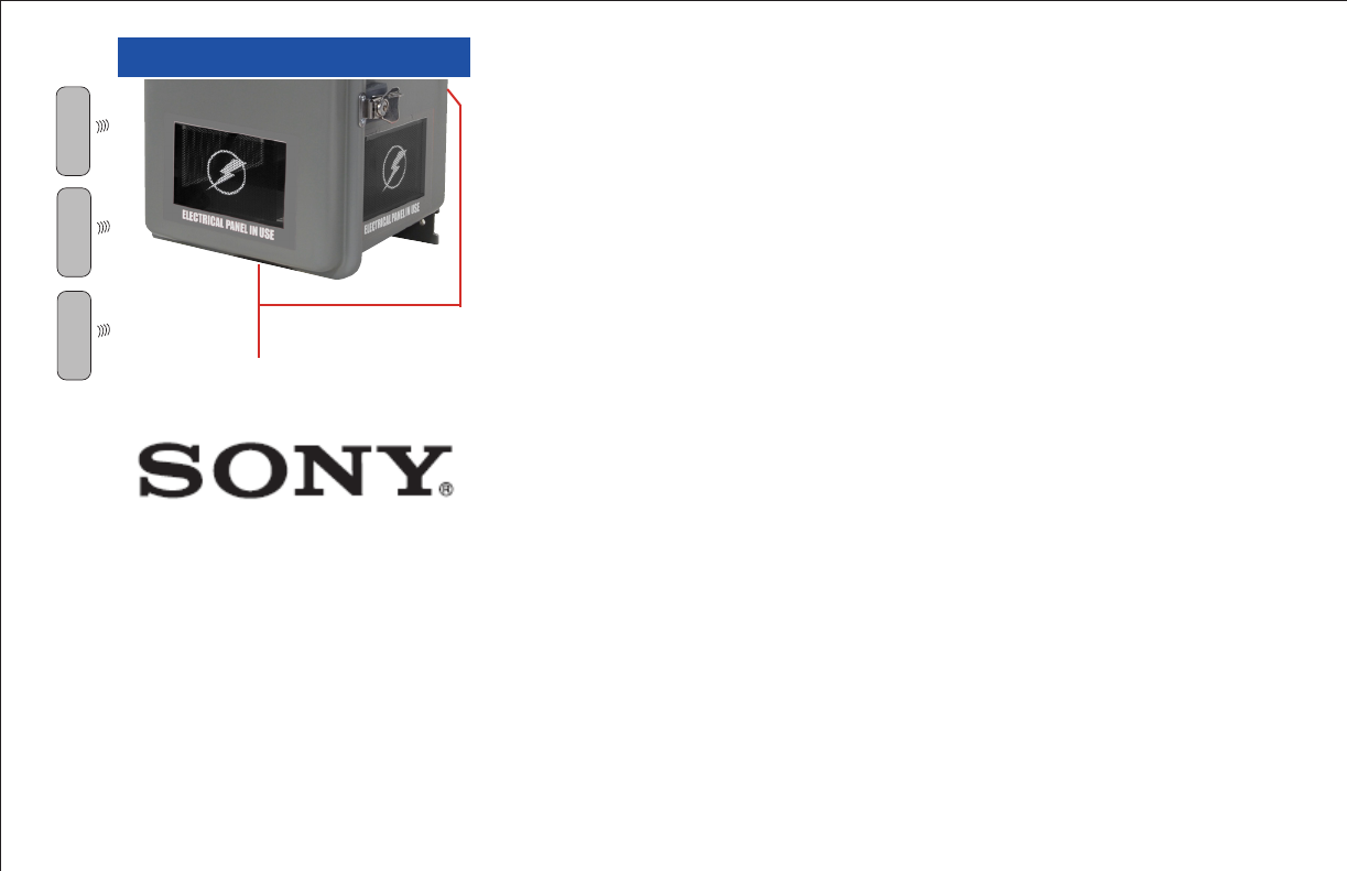
OPERATION
Concealed Camera Ports
There are three concealed camera ports on the Utility Box. Each port
is disguised with an ELECTRICAL PANEL IN USE label. Keep the label
surface clean and free from scuff marks. Make sure nothing blocks this
area.
A combination of two labels and an interior screen are installed per
window. Three additional labels (one per window) are also included in the
accessory kit. The installed label set and interior screen will provide the
best camera performance while balancing covert appearance issues, such
as reflection and light penetration from the other windows. The additional
(accessory bag) labels can be customer-applied if desired. You must be
willing to accept some honeycomb effect in the video at lower camera zoom
settings in order to cover up the tinted glass area of the windows.
Ventilation and Thermal Considerations
The Utility Box has a louvered exhaust vent on the back and a wire mesh
intake vent on the bottom of the enclosure. A cooling fan is mounted inside
of one of these ports. The cooling fan and heater run automatically to keep
the MiniBox-4 operating temperature between –20C (-4F) and +50C (122F).
Foam mesh filtration protects against water/dirt invasion.
Optional Analog and Digital transmitters feature a thermal shut-down
circuit to protect the transmitter if the inside of the MiniBox-4 gets too
hot. Always remove obstructions from the vents to ensure good air flow.
Vacuum the bottom vent to remove excess dust, Remove the rear louvers,
clean and replace the foam filter if needed.
Do NOT block airow to vents at
back and bottom of MiniBox-4
A
N LOG
W
D
DTC COMMUNICATIONS, INC. 19
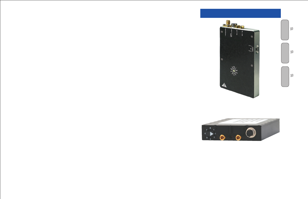
OPERATION
Analog Video Transmitter
The optional analog DTC Video Transmitter is built into the MiniBox-4
along with two microwave patch antennas. The analog video transmitter
features ten user-programmable channels. A label on the inside door
of the MiniBox-4 lists the factory-set frequencies. Access to the serial
programming connector and channel switch are provided on the MiniBox-
4 Control Panel. Programming should be performed at the factory or by a
trained depot technician using DTC’s Universal Programming software.
Digital Video Transmitter
The optional DTC Palladium II Digital Video Transmitter is built into
the MiniBox-4 along with two microwave patch antennas. The video
transmitter features eight user-programmable channels. A label on the
inside door of the MiniBox-4 lists the factory set frequencies. Access to
the serial programming connector and channel switch are provided on the
MiniBox-4 Control Panel. Programming should be performed at the factory
or by a trained depot technician using DTC’s Palladium Programming
software.
Optional Analog Video Transmitter
Optional Digital Video Transmitter
Sony Camera & PTZ Platform
The MiniBox-4 features a SONY high resolution color camera with 26X
optical and 12X digital zoom. The SONY camera has its own pan/tilt
mechanism and is hidden behind three concealed camera ports in the
utility box. DTMF commands (transmitter models) or browser-based
commands allow for control of pan, tilt, zoom, focus, and auto focus. The
SONY camera works well in low light situations. The camera orientation
can be panned to left, right, or front view ports.
W
A
N LOG
W
D
DTC COMMUNICATIONS, INC.
20
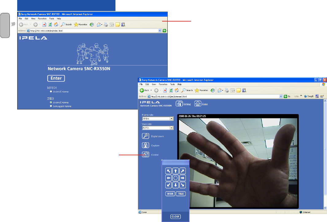
OPERATION
Start
Screen
Click 2X
to Display
Remote
Control
Web Access
Type the MiniBox-4 IP address from
page 14 into your web browser and
you should see the Start Screen
(left). Click Enter to view the Video
Screen (below). Click Control to
access the Controls (right) or click
twice to access the Remote Control
(below).
W