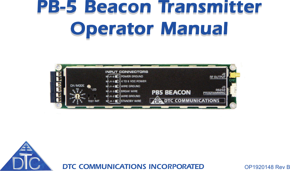
DTC Communications PB5-150 Surveillance Beacon for Law Enforcement User Manual VTX 1920255

DTC Communications Inc. Surveillance Beacon for Law Enforcement VTX 1920255

Exhibit D Users Manual per 2 1033 c3

DTC COMMUNICATIONS INCORPORATED                 OP1920148 Rev BPB-5 Beacon TPB-5 Beacon TPB-5 Beacon TPB-5 Beacon TPB-5 Beacon TransmitterransmitterransmitterransmitterransmitterOperator ManualOperator ManualOperator ManualOperator ManualOperator ManualPB-5 Beacon TPB-5 Beacon TPB-5 Beacon TPB-5 Beacon TPB-5 Beacon TransmitterransmitterransmitterransmitterransmitterOperator ManualOperator ManualOperator ManualOperator ManualOperator Manual
DTC COMMUNICATIONS, INC.2How to contact DTCFor operator and troubleshootinginformation, customers are encouraged to refer tothe details in this manual. For additional clarificationor instruction, or to order parts, contact DTC.Customer Service is available Monday throughFriday between the hours of 9:00 AM and 5:00 PMEST at:Tel: 603-880-4411Fax: 603-880-6965Website: www.dtccom.comEmail: info@dtccom.com486 Amherst StreetNashua, New Hampshire 03063USACopyright NoticeCopyright © 2002DTC Communications, Inc. All rightsreserved. No part of this document may bereproduced, transmitted, transcribed, stored in a re-trieval system or translated into anylanguage or computer language, in any form or byany means, including but not limited to electronic,magnetic, mechanical, optical, chemical, manual orotherwise, without the prior written permission of DTCCommunications, Inc.DisclaimerThe information in the document is subject to changewithout notice. DTC makes no representations or war-ranties with respect to the contents hereof, and spe-cifically disclaims any implied warranties of merchant-ability or fitness for a particular purpose. DTC reservesthe right to revise this publication and to make changesfrom time to time in the content hereof without obliga-tion of DTC to notify any person of such revision orchanges.TrademarksTrademarks of DTC Communications, Inc. include:• DTC• MiniPIX®• DynaPIX®Other product names used in this manual are the prop-erties of their respective owners.WarrantyDTC warrants its manufactured components againstdefects in material and workmanship for a period oftwo (2) years, commencing on the date of original pur-chase.Products manufactured by others that are approvedfor use with DTC equipment are warranted for themanufacturer’s warranty period, commencing from thedate of shipment from DTC.FCC informationForms can be obtained from the FCC on their web-site at:www.fcc.govYou can also contact the FCC using their FAX backservice at: (888) 418-3676Additional instructions are available by telephone at:(888) 225-5322The filing fee form is returned to:Federal Communications Commission1270 Fairfield RoadGettysburg, PA 17325-7245
DTC COMMUNICATIONS, INC. 3NOTE Describes special issues you should be awareof while using a particular function.WARNING Calls out situations in which equipmentcould be damaged or a process could be incorrectlyimplemented, but in which operator safety is not afactor.TIP Describes application hints.Manual Conventions    Feature Description  TABLE OF CONTENTSOverview ............................................................................. 5Connections ........................................................................ 7Quick Start .......................................................................... 8Optional Accessories .......................................................... 8Specifications .................................................................... 10Programming Introduction ................................................ 12Installing Programming Software ...................................... 13Programming Procedure ................................................... 14• Allows the unit to be frequencyversatile.• Allows user to program multiplefeature sets and access them inthe field through a 10 positionswitch. This switch is only read atpower up.• This allows various size batterypacks to be connected.• Track Mode’s primary purpose isto allow a tracking receiver tolocate and track the beacon.• Event Mode’s primary purpose isto indicate the status of the breakwire.SynthesizerProgrammableExternal BatteryModes ofOperation
DTC COMMUNICATIONS, INC.4DTC Communications, Inc. (DTC) warrants its RF transmitting and receiving products to be free fromdefects in workmanship or material for a period of two (2) years from the date of shipment unlessotherwise stated.The liability of DTC, Inc. under this warranty is limited to replacing, repairing, or issuing credit, atoption, for any products, which are returned by the purchaser during such warranty period, provided:DTC is notified and a Repair Authorization Number is issued by DTC Customer Service within 30 daysafter discovery of such defects by Customer.The defective units are returned to DTC with transportation charged Prepaid by the Customer.Product damaged in shipment must be reported to and claim forms filed with the Carrier by theCustomer.  In shipments to the factory, notice and claim procedures will be initiated by DTC.DTC’s examination of such products shall disclose to its satisfaction that such defects exist and havenot been caused by misuse, misapplication, neglect, improper installation, improper storage, alter-ation, physical damage or accidents.The warranty shall not apply to microphones, batteries, antennas, crystals or material ordinarilysusceptible to field damage or any accessories of a disposable nature. The warranty shall not apply toEngineering Prototypes or Customer requested modifications to electronic circuits.This warranty does not apply to and DTC does not independently warrant items or systems sold byDTC which are produced by other manufacturers.  With respect to such items, the Customer shall lookto the warranty of the original manufacturer and DTC disclaims all warranty, expressed or implied.Nothing in this warranty, or any statement, brochure, bulletin, or advertisement is to be interpreted asestablishing the suitability of any product for particular application or use.  Applications of the productand the determination of suitability for any application, is the sole responsibility of the Customer.             TWO YEAR WARRANTY
DTC COMMUNICATIONS, INC. 5INTRODUCTIONThe PB-5 is a reliable, fully synthesized, user programmable, one watt, package beacon.It has a number of unique features. Two modes of operation allow you to track or monitor a package using a DTC TRAK/Rsystem or a VHF-FM receiver, Tracker mode and Event mode. The beacon’s two primary connections are the break wireand the standby wire. When the break wire is broken the alarm is activated, which is transmitted to the receiver. When thestandby wire is removed, the transmitter wakes up and begins its pre-configured actions. The configuration options includethe ability to enable or disable the motion sense feature, event or track, and deviation settings.TRACKER MODEFor tracking a letter or package, Tracker mode is used in conjunction with the DTC TRAK/R system. In the Tracker mode, thePB-5 will send pulses to the  DTC TRAK/R system at various repetition rates to signal that the package is stationary or inmotion and to identify location. The PB-5 Tracker mode is intended to be used with DTC’s TRAK/R systems. When the PB-5is in Tracker Mode, it transmits pulses, which alerts the TRAK/R operator to the condition of the PB-5. The pulses produced bythe PB-5 can be directly monitored or converted to signal strength tones through the TRAK/R system. The pulse is a group offour 15 millisecond pulses, spaced 15 milliseconds apart.•StationaryStationary mode is transmitted when physical movement has not been detected for at least 4 seconds, but less than 30minutes. At power up, the PB-5 defaults to stationary condition. The pulses are transmitted every two seconds instationary condition.•ParkedParked condition is transmitted when physical movement has not been detected for 30 minutes. The pulses aretransmitted every four seconds in parked condition.•MotionWhen physical movement has been detected, the PB-5 will transmit in the motion condition. The pulses are transmittedevery second in the motion condition.•Break WireIf the break wire is broken, the unit goes into alarm mode and sends out alarm tones once a second (interleaved withtracking pulses also occurring once per second).•Standby WireIf the standby wire feature is used, then the unit will not begin to send tones until standby is exited (the alarm featurewill still work normally).OVERVIEW
DTC COMMUNICATIONS, INC.6OVERVIEWEVENT MODEWhile in Event mode, the PB-5 transmits confidence tones at a default rate of 30 second intervals. When the Break Wire isbroken (circuit is opened), the PB-5 will alert the agent that the package or door has been opened. The PB-5 quickly changesthe tone transmission to the easily recognized alarm signal. The alarm signal transmits twice per second.BREAK WIRE INPUTThe break wire input on the PB-5 will detect a change-of-state. This means that you can use the break wire in the traditionalway and use a wire loop from the Break wire pin to the ground pin on the terminal strip. After the power is applied, if the loopbreaks the alarm will go off. If you want, you can use a normally-open switch as well; just connect the switch between theBreak wire and GROUND pins, and the alarm will go off if the switch is closed.STANDBY WIREThe standby wire input allows you to put the PB-5 into a standby mode.  When a wire loop is connected between theSTANDBY pin and the ground pin on the terminal strip, before or during normal operation, the PB-5 will be on hold, noconfidence tones. This will preserve valuable battery power. When the STANDBY loop is broken the PB-5 will then beginconfidence tone transmissions and normal operation.Note: Regardless of the standby wire loop condition, if break wire loop is broken the PB-5 will begin to alarm.Channel/Mode switchThere are ten user programmable modes selectable via the 10-position switch. The mode switch will only be read at power upor upon re-initialization. Changing the mode switch while the unit is running will have no effect.LEDThe diagnostic LED on the PB-5 is on the top of the case, clearly marked. The LED will flash once on power up to indicatethat the transmitter has checked its memory and is ready for deployment. If the PB-5 senses an internal problem the LED willflash three times.CONNECTIONS
DTC COMMUNICATIONS, INC. 7CONNECTIONSTest Push-buttonHolding this push-button, while powering up, causes the unit to go into test mode.Based on the break wire and standby wire inputs, the unit will go into one of thefour transmit modes.Break wire Standby wire Transmit OutputNone None Continuous ToneNone In Continuous ToneIn None Tracking PulsesIn In Unmodulated CarrierInit Push-buttonHolding the init switch for one second, re-initializes the unit. It reads the mode/channel switch and can be used to change the channel/mode without cycling thepower. The LED blinks once. If the init switch is held for more than 5 seconds, theunit is switched to default mode. This is indicated by 5 LED blinks, a short delay,and then one LED blink.     Default Settings:Tone: 1000 Hz on all channelsDefault Confidence tone interval: 30 secondsBattery Monitoring: DisabledStandby: On closed on all channelsBreak wire: Auto configured on all channelsRF OutputConnect the antenna to this connector.RS232 ConnectorThe programming cable is connected to this connector when programming isrequired.Channel/Mode switch        LED lightTest push-button          Init push-buttonAntenna connectorProgramming Cable Connector
DTC COMMUNICATIONS, INC.8PB-5 Beacon TransmitterQUICK STARTWhat should you expect to receive with yourPB5 Beacon Transmitter?1 PB-5 Beacon Transmitter1 Antenna1 Screwdriver1 DTC programming software package1 DTC programming cable2 Battery Pack with batteries1 Test CableOPTIONAL ACCESSORIESPart Number Description4044359 Antenna4045163 Programming Cable8002025 Programming Software8590094 Battery Snap with flying leadsPart Number Description8590093 Battery Holder for 4 AA batteries4044348 Test Cable, MMCX to BNC
DTC COMMUNICATIONS, INC. 9ANTENNAPROGRAMMINGCABLECHANNEL/MODE SWITCHINIT PUSH-BUTTONTEST PUSH-BUTTONBREAKWIRESTANDBYWIRELEDPOWERQUICK START1Connect an antenna to the RF Output connector on the transmitter.2Connect the break wire and or standby wire depending on the desired configuration.3Using the supplied screwdriver, turn the channel selector to the correct channel number.4Connect the power source to the PB-5’s power terminals.5If standby wire is used the PB-5 will not be enabled until the wire is removed. You will have to remove the wire toactivate.6If standby wire is not used, the PB-5 is activated immediately, and will operate within the programmed parameters.7If the default settings are not the desired settings, then programming is required. Go to the programming section onpage 12 to program the PB-5 with new settings.25134Warning: Do not apply power to the transmitteruntil an antenna has been connected in step 1.Warning: Do not exceed 7.5 Volts
DTC COMMUNICATIONS, INC.10SPECIFICATIONS Specifications for the PB-5 TransmitterDimensions 5.0” L x 1.2” W x 0.35” HControls and Indicators • 10 position rotary channel/mode switch• Initialize push-button switch• Test push-button switch• LED indicatorConnectors • RF output: Type MMCX• Battery Power: 5mm screw terminal strip 2 ckt• Standby Wire: 5mm screw terminal strip 2 ckt• Break Wire: 5mm screw terminal strip 2 cktFrequency Stability Within +/- 2.5 ppm over -30° C to +60° CRF Output power into a50 Ohm load 1.0 W @ 6.0 VDC supplyChannel Capacity 10 User programmable via RS232 with PC running DTCfrequency/configuration application.Frequency Range • 150 - 174 MHz (VHF-High)• 138 - 150 MHz (Option VHF-Low)• 210 - 225 MHz (Option UHF-Low)Modulation Modes • Tracking modes• Event modes• Deviation: User programmable• NTIA compliant +/- 2.5 kHz max or +/- 5 kHz maxSpurious & Harmonic Greater than -60 dBc (non-harmonic)Attenuation Greater than -50 dBc (harmonic)Transmitter side-band Greater than 50 dBc at greater +/- 10 kHzsuppressionAM Hum and Noise Greater than 34 dB down from rated deviationattenuationFM Hum and Noise Greater than 34 dB down from rated deviationattenuationOperating Temp. Range -30° C to +60° COperating Voltage Range 4.0 VDC to 7.2 VDC
DTC COMMUNICATIONS, INC. 11Specifications for the PB-5 TransmitterRF Output Load-stability Stable into a VSWR of 8 to 1 or betterWeight 1.6 ounces (less batteries)Power Source Four AA batteries (external)Battery Life Four AA batteries (Duracell MN1500 rated at 2450 mAH) willtransmit in confidence mode for more than 400 hours.Current Drain • Standby: 200 uA Max• Active Transmit: 350 mA peak (1.0 Watt @ 6 V with  50 Ohm antennaNVRam settings Tone: 1000 Hz on all channels(Default) Default Confidence tone interval: 30 secondsBattery Monitoring: DisabledStandby: On closed on all channelsBreak wire: Auto configured on all channels SPECIFICATIONS
DTC COMMUNICATIONS, INC.12IntroductionWhen you order a PB-5 Beacon transmitter, DTC will factory program yourfrequencies at no additional charge to you. This is often the best path for state andlocal agencies with limited frequencies available to them.DTC will also provide you with free software and a free programming cable,enabling you to change your  frequencies. This is ideal if you often work with otheragencies, or anticipate the equipment being used by a multi-jurisdictional taskforce. You can program up to ten channel settings per unit.  In general, this allowsyou to program most variations you might encounter in the field at the depot level.TIP: Make sure that you program your transmitter to match the frequencies ofyour receiver, and test the components as a system prior to going into thefield! PROGRAMMING
DTC COMMUNICATIONS, INC. 13PROGRAMMINGInstalling DTC Universal Programming Software on your PCNOTE: Uninstall any previous versions by going to Add/Remove Programs,clicking on DTC Universal Programming, and clicking on uninstall.1Click on Start, click on run.2Click on the Browse button.3Click on or find your CD drive.4Install the JAVA Runtime Environment Application first (CD provided).5Follow the  install wizard screens.6Install the Universal Programming software next (floppy provided).7Click on Start, click on run.8Click on the Browse Button.9Click on your floppy drive.10 Double click on the setup.11 Follow the install wizard screens.Your programming software is installed.
DTC COMMUNICATIONS, INC.14PROGRAMMING1Connect the antenna to the PB-5.2Install the programming cable into the RS232connector on the PB-5.3Plug the serial cable of the programming cableinto the COM1 or COM2 port of your computer.4Select Start, programs, DTC communications onyour computer.5The system allows you to select device  COM1 orCOM2, depending on which serial port you areconnected to.The cycle power screen displays.6Connect the battery pack to the PB-5 and clickOK.A message screen displays PB-5 downloading.7Click on the TX Tab of the screen.8Click on the channel you need to change and clickon the Edit Channel button.9Enter the new settings in the “Enter newFrequency screen. You can also makechanges to the width, motion detect, andthe mode.10 Click on the OK button.Serial Port ofcomputer: COM1or COM2AntennaPOWER
DTC COMMUNICATIONS, INC. 155The programming software returns to the TX screen with your newsettings displayed, and an asterick (*) besidethe channel that has changed.11 Click on the upload button.A message screen displays the new settingsbeing uploaded to device.A message screen displays that your settingshave been successfully uploaded.Your new settings have been installed.PROGRAMMING
486 Amherst Street • Nashua, New Hampshire 03063 • 603-880- 4411  www.dtccom.com

Navigation menu