DTC Communications PB5-150 Surveillance Beacon for Law Enforcement User Manual VTX 1920255
DTC Communications Inc. Surveillance Beacon for Law Enforcement VTX 1920255
Exhibit D Users Manual per 2 1033 c3
DTC COMMUNICATIONS INCORPORATED OP1920148 Rev B
PB-5 Beacon TPB-5 Beacon T
PB-5 Beacon TPB-5 Beacon T
PB-5 Beacon Transmitterransmitter
ransmitterransmitter
ransmitter
Operator ManualOperator Manual
Operator ManualOperator Manual
Operator Manual
PB-5 Beacon TPB-5 Beacon T
PB-5 Beacon TPB-5 Beacon T
PB-5 Beacon Transmitterransmitter
ransmitterransmitter
ransmitter
Operator ManualOperator Manual
Operator ManualOperator Manual
Operator Manual

DTC COMMUNICATIONS, INC.
2
How to contact DTC
For operator and troubleshooting
information, customers are encouraged to refer to
the details in this manual. For additional clarification
or instruction, or to order parts, contact DTC.
Customer Service is available Monday through
Friday between the hours of 9:00 AM and 5:00 PM
EST at:
Tel: 603-880-4411
Fax: 603-880-6965
Website: www.dtccom.com
Email: info@dtccom.com
486 Amherst Street
Nashua, New Hampshire 03063
USA
Copyright Notice
Copyright © 2002
DTC Communications, Inc. All rights
reserved. No part of this document may be
reproduced, transmitted, transcribed, stored in a re-
trieval system or translated into any
language or computer language, in any form or by
any means, including but not limited to electronic,
magnetic, mechanical, optical, chemical, manual or
otherwise, without the prior written permission of DTC
Communications, Inc.
Disclaimer
The information in the document is subject to change
without notice. DTC makes no representations or war-
ranties with respect to the contents hereof, and spe-
cifically disclaims any implied warranties of merchant-
ability or fitness for a particular purpose. DTC reserves
the right to revise this publication and to make changes
from time to time in the content hereof without obliga-
tion of DTC to notify any person of such revision or
changes.
Trademarks
Trademarks of DTC Communications, Inc. include:
• DTC
• MiniPIX®
• DynaPIX®
Other product names used in this manual are the prop-
erties of their respective owners.
Warranty
DTC warrants its manufactured components against
defects in material and workmanship for a period of
two (2) years, commencing on the date of original pur-
chase.
Products manufactured by others that are approved
for use with DTC equipment are warranted for the
manufacturer’s warranty period, commencing from the
date of shipment from DTC.
FCC information
Forms can be obtained from the FCC on their web-
site at:
www.fcc.gov
You can also contact the FCC using their FAX back
service at: (888) 418-3676
Additional instructions are available by telephone at:
(888) 225-5322
The filing fee form is returned to:
Federal Communications Commission
1270 Fairfield Road
Gettysburg, PA 17325-7245

DTC COMMUNICATIONS, INC. 3
NOTE Describes special issues you should be aware
of while using a particular function.
WARNING Calls out situations in which equipment
could be damaged or a process could be incorrectly
implemented, but in which operator safety is not a
factor.
TIP Describes application hints.
Manual Conventions
Feature Description
TABLE OF CONTENTS
Overview ............................................................................. 5
Connections ........................................................................ 7
Quick Start .......................................................................... 8
Optional Accessories .......................................................... 8
Specifications .................................................................... 10
Programming Introduction ................................................ 12
Installing Programming Software ...................................... 13
Programming Procedure ................................................... 14
• Allows the unit to be frequency
versatile.
• Allows user to program multiple
feature sets and access them in
the field through a 10 position
switch. This switch is only read at
power up.
• This allows various size battery
packs to be connected.
• Track Mode’s primary purpose is
to allow a tracking receiver to
locate and track the beacon.
• Event Mode’s primary purpose is
to indicate the status of the break
wire.
Synthesizer
Programmable
External Battery
Modes of
Operation

DTC COMMUNICATIONS, INC.
4
DTC Communications, Inc. (DTC) warrants its RF transmitting and receiving products to be free from
defects in workmanship or material for a period of two (2) years from the date of shipment unless
otherwise stated.
The liability of DTC, Inc. under this warranty is limited to replacing, repairing, or issuing credit, at
option, for any products, which are returned by the purchaser during such warranty period, provided:
DTC is notified and a Repair Authorization Number is issued by DTC Customer Service within 30 days
after discovery of such defects by Customer.
The defective units are returned to DTC with transportation charged Prepaid by the Customer.
Product damaged in shipment must be reported to and claim forms filed with the Carrier by the
Customer. In shipments to the factory, notice and claim procedures will be initiated by DTC.
DTC’s examination of such products shall disclose to its satisfaction that such defects exist and have
not been caused by misuse, misapplication, neglect, improper installation, improper storage, alter-
ation, physical damage or accidents.
The warranty shall not apply to microphones, batteries, antennas, crystals or material ordinarily
susceptible to field damage or any accessories of a disposable nature. The warranty shall not apply to
Engineering Prototypes or Customer requested modifications to electronic circuits.
This warranty does not apply to and DTC does not independently warrant items or systems sold by
DTC which are produced by other manufacturers. With respect to such items, the Customer shall look
to the warranty of the original manufacturer and DTC disclaims all warranty, expressed or implied.
Nothing in this warranty, or any statement, brochure, bulletin, or advertisement is to be interpreted as
establishing the suitability of any product for particular application or use. Applications of the product
and the determination of suitability for any application, is the sole responsibility of the Customer.
TWO YEAR WARRANTY

DTC COMMUNICATIONS, INC. 5
INTRODUCTION
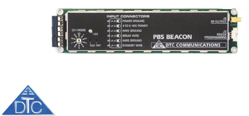
The PB-5 is a reliable, fully synthesized, user programmable, one watt, package beacon.
It has a number of unique features. Two modes of operation allow you to track or monitor a package using a DTC TRAK/R
system or a VHF-FM receiver, Tracker mode and Event mode. The beacon’s two primary connections are the break wire
and the standby wire. When the break wire is broken the alarm is activated, which is transmitted to the receiver. When the
standby wire is removed, the transmitter wakes up and begins its pre-configured actions. The configuration options include
the ability to enable or disable the motion sense feature, event or track, and deviation settings.
TRACKER MODE
For tracking a letter or package, Tracker mode is used in conjunction with the DTC TRAK/R system. In the Tracker mode, the
PB-5 will send pulses to the DTC TRAK/R system at various repetition rates to signal that the package is stationary or in
motion and to identify location. The PB-5 Tracker mode is intended to be used with DTC’s TRAK/R systems. When the PB-5
is in Tracker Mode, it transmits pulses, which alerts the TRAK/R operator to the condition of the PB-5. The pulses produced by
the PB-5 can be directly monitored or converted to signal strength tones through the TRAK/R system. The pulse is a group of
four 15 millisecond pulses, spaced 15 milliseconds apart.
•Stationary
Stationary mode is transmitted when physical movement has not been detected for at least 4 seconds, but less than 30
minutes. At power up, the PB-5 defaults to stationary condition. The pulses are transmitted every two seconds in
stationary condition.
•Parked
Parked condition is transmitted when physical movement has not been detected for 30 minutes. The pulses are
transmitted every four seconds in parked condition.
•Motion
When physical movement has been detected, the PB-5 will transmit in the motion condition. The pulses are transmitted
every second in the motion condition.
•Break Wire
If the break wire is broken, the unit goes into alarm mode and sends out alarm tones once a second (interleaved with
tracking pulses also occurring once per second).
•Standby Wire
If the standby wire feature is used, then the unit will not begin to send tones until standby is exited (the alarm feature
will still work normally).
OVERVIEW

DTC COMMUNICATIONS, INC.
6
OVERVIEW
EVENT MODE
While in Event mode, the PB-5 transmits confidence tones at a default rate of 30 second intervals. When the Break Wire is
broken (circuit is opened), the PB-5 will alert the agent that the package or door has been opened. The PB-5 quickly changes
the tone transmission to the easily recognized alarm signal. The alarm signal transmits twice per second.
BREAK WIRE INPUT
The break wire input on the PB-5 will detect a change-of-state. This means that you can use the break wire in the traditional
way and use a wire loop from the Break wire pin to the ground pin on the terminal strip. After the power is applied, if the loop
breaks the alarm will go off. If you want, you can use a normally-open switch as well; just connect the switch between the
Break wire and GROUND pins, and the alarm will go off if the switch is closed.
STANDBY WIRE
The standby wire input allows you to put the PB-5 into a standby mode. When a wire loop is connected between the
STANDBY pin and the ground pin on the terminal strip, before or during normal operation, the PB-5 will be on hold, no
confidence tones. This will preserve valuable battery power. When the STANDBY loop is broken the PB-5 will then begin
confidence tone transmissions and normal operation.
Note: Regardless of the standby wire loop condition, if break wire loop is broken the PB-5 will begin to alarm.
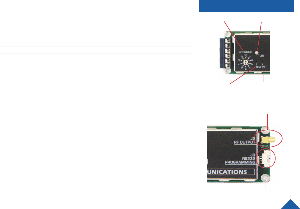
Channel/Mode switch
There are ten user programmable modes selectable via the 10-position switch. The mode switch will only be read at power up
or upon re-initialization. Changing the mode switch while the unit is running will have no effect.
LED
The diagnostic LED on the PB-5 is on the top of the case, clearly marked. The LED will flash once on power up to indicate
that the transmitter has checked its memory and is ready for deployment. If the PB-5 senses an internal problem the LED will
flash three times.
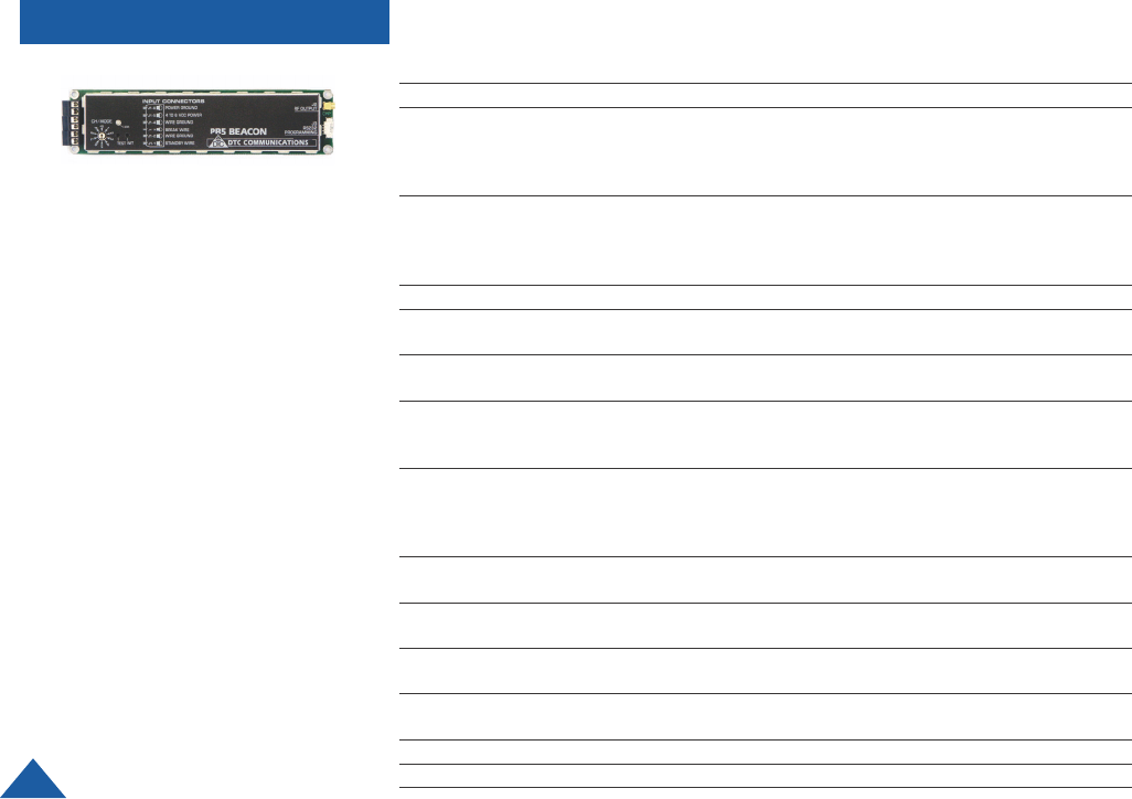
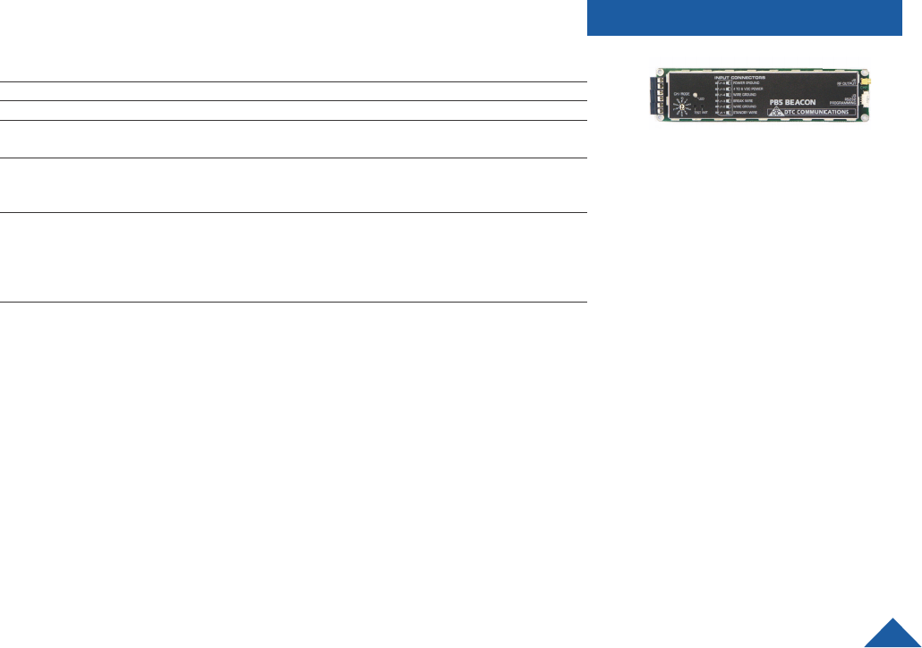
CONNECTIONS
DTC COMMUNICATIONS, INC. 7
CONNECTIONS
Test Push-button
Holding this push-button, while powering up, causes the unit to go into test mode.
Based on the break wire and standby wire inputs, the unit will go into one of the
four transmit modes.
Break wire Standby wire Transmit Output
None None Continuous Tone
None In Continuous Tone
In None Tracking Pulses
In In Unmodulated Carrier
Init Push-button
Holding the init switch for one second, re-initializes the unit. It reads the mode/
channel switch and can be used to change the channel/mode without cycling the
power. The LED blinks once. If the init switch is held for more than 5 seconds, the
unit is switched to default mode. This is indicated by 5 LED blinks, a short delay,
and then one LED blink. Default Settings:
Tone: 1000 Hz on all channels
Default Confidence tone interval: 30 seconds
Battery Monitoring: Disabled
Standby: On closed on all channels
Break wire: Auto configured on all channels
RF Output
Connect the antenna to this connector.
RS232 Connector
The programming cable is connected to this connector when programming is
required.
Channel/Mode switch LED light
Test push-button Init push-button
Antenna connector
Programming Cable Connector
DTC COMMUNICATIONS, INC.
8
PB-5 Beacon Transmitter
QUICK START
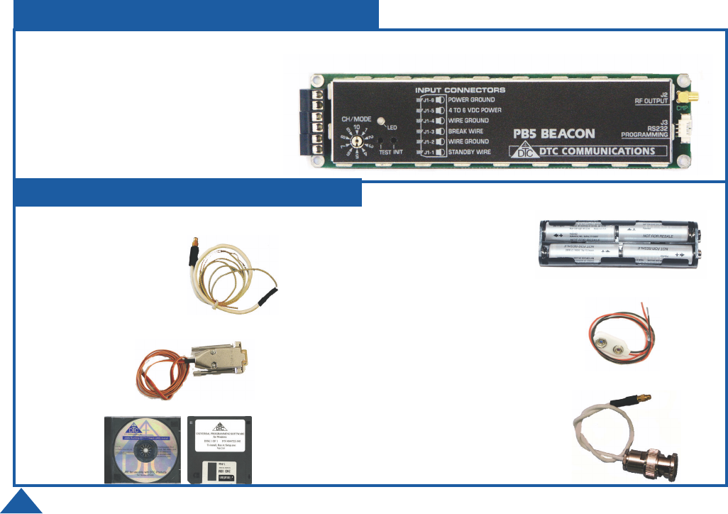
What should you expect to receive with your
PB5 Beacon Transmitter?
1 PB-5 Beacon Transmitter
1 Antenna
1 Screwdriver
1 DTC programming software package
1 DTC programming cable
2 Battery Pack with batteries
1 Test Cable
OPTIONAL ACCESSORIES
Part Number Description
4044359 Antenna
4045163 Programming Cable
8002025 Programming Software
8590094 Battery Snap with flying leads
Part Number Description
8590093 Battery Holder for 4 AA batteries
4044348 Test Cable, MMCX to BNC
DTC COMMUNICATIONS, INC. 9
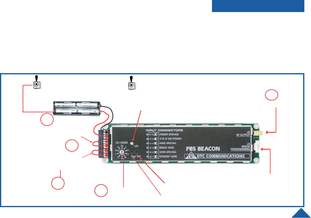
ANTENNA
PROGRAMMING
CABLE
CHANNEL/
MODE SWITCH
INIT PUSH-BUTTON
TEST PUSH-BUTTON
BREAKWIRE
STANDBY
WIRE
LED
POWER
QUICK START
1Connect an antenna to the RF Output connector on the transmitter.
2Connect the break wire and or standby wire depending on the desired configuration.
3Using the supplied screwdriver, turn the channel selector to the correct channel number.
4Connect the power source to the PB-5’s power terminals.
5If standby wire is used the PB-5 will not be enabled until the wire is removed. You will have to remove the wire to
activate.
6If standby wire is not used, the PB-5 is activated immediately, and will operate within the programmed parameters.
7If the default settings are not the desired settings, then programming is required. Go to the programming section on
page 12 to program the PB-5 with new settings.
2
5
1
3
4
Warning: Do not apply power to the transmitter
until an antenna has been connected in step 1.
Warning: Do not exceed 7.5 Volts
DTC COMMUNICATIONS, INC.
10
SPECIFICATIONS Specifications for the PB-5 Transmitter
Dimensions 5.0” L x 1.2” W x 0.35” H
Controls and Indicators • 10 position rotary channel/mode switch
• Initialize push-button switch
• Test push-button switch
• LED indicator
Connectors • RF output: Type MMCX
• Battery Power: 5mm screw terminal strip 2 ckt
• Standby Wire: 5mm screw terminal strip 2 ckt
• Break Wire: 5mm screw terminal strip 2 ckt
Frequency Stability Within +/- 2.5 ppm over -30° C to +60° C
RF Output power into a
50 Ohm load 1.0 W @ 6.0 VDC supply
Channel Capacity 10 User programmable via RS232 with PC running DTC
frequency/configuration application.
Frequency Range • 150 - 174 MHz (VHF-High)
• 138 - 150 MHz (Option VHF-Low)
• 210 - 225 MHz (Option UHF-Low)
Modulation Modes • Tracking modes
• Event modes
• Deviation: User programmable
• NTIA compliant +/- 2.5 kHz max or +/- 5 kHz max
Spurious & Harmonic Greater than -60 dBc (non-harmonic)
Attenuation Greater than -50 dBc (harmonic)
Transmitter side-band Greater than 50 dBc at greater +/- 10 kHz
suppression
AM Hum and Noise Greater than 34 dB down from rated deviation
attenuation
FM Hum and Noise Greater than 34 dB down from rated deviation
attenuation
Operating Temp. Range -30° C to +60° C
Operating Voltage Range 4.0 VDC to 7.2 VDC
DTC COMMUNICATIONS, INC. 11
Specifications for the PB-5 Transmitter
RF Output Load-stability Stable into a VSWR of 8 to 1 or better
Weight 1.6 ounces (less batteries)
Power Source Four AA batteries (external)
Battery Life Four AA batteries (Duracell MN1500 rated at 2450 mAH) will
transmit in confidence mode for more than 400 hours.
Current Drain • Standby: 200 uA Max
• Active Transmit: 350 mA peak (1.0 Watt @ 6 V with
50 Ohm antenna
NVRam settings Tone: 1000 Hz on all channels
(Default) Default Confidence tone interval: 30 seconds
Battery Monitoring: Disabled
Standby: On closed on all channels
Break wire: Auto configured on all channels
SPECIFICATIONS
DTC COMMUNICATIONS, INC.
12
Introduction
When you order a PB-5 Beacon transmitter, DTC will factory program your
frequencies at no additional charge to you. This is often the best path for state and
local agencies with limited frequencies available to them.
DTC will also provide you with free software and a free programming cable,
enabling you to change your frequencies. This is ideal if you often work with other
agencies, or anticipate the equipment being used by a multi-jurisdictional task
force. You can program up to ten channel settings per unit. In general, this allows
you to program most variations you might encounter in the field at the depot level.
TIP: Make sure that you program your transmitter to match the frequencies of
your receiver, and test the components as a system prior to going into the
field!
PROGRAMMING
DTC COMMUNICATIONS, INC. 13
PROGRAMMING
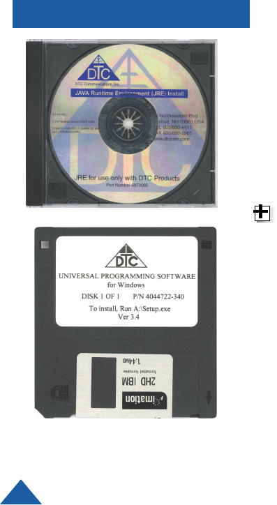
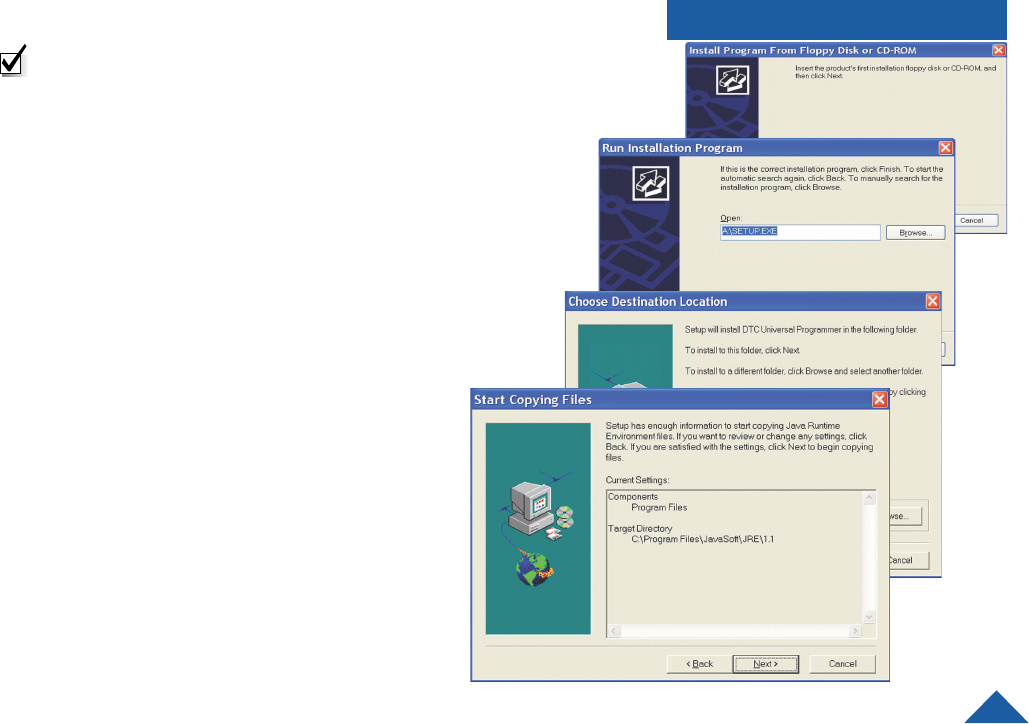
Installing DTC Universal Programming Software on your PC
NOTE: Uninstall any previous versions by going to Add/Remove Programs,
clicking on DTC Universal Programming, and clicking on uninstall.
1Click on Start, click on run.
2Click on the Browse button.
3Click on or find your CD drive.
4Install the JAVA Runtime Environment Application first (CD provided).
5Follow the install wizard screens.
6Install the Universal Programming software next (floppy provided).
7Click on Start, click on run.
8Click on the Browse Button.
9Click on your floppy drive.
10 Double click on the setup.
11 Follow the install wizard screens.
Your programming software is installed.
DTC COMMUNICATIONS, INC.
14
PROGRAMMING
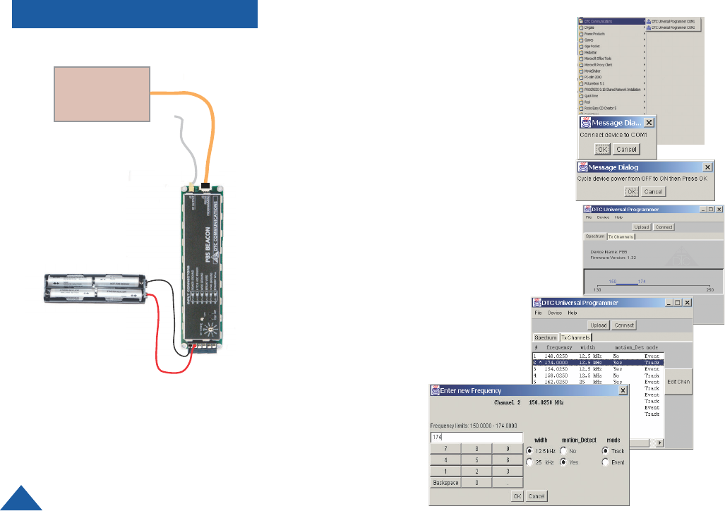
1Connect the antenna to the PB-5.
2Install the programming cable into the RS232
connector on the PB-5.
3Plug the serial cable of the programming cable
into the COM1 or COM2 port of your computer.
4Select Start, programs, DTC communications on
your computer.
5The system allows you to select device COM1 or
COM2, depending on which serial port you are
connected to.
The cycle power screen displays.
6Connect the battery pack to the PB-5 and click
OK.
A message screen displays PB-5 downloading.
7Click on the TX Tab of the screen.
8Click on the channel you need to change and click
on the Edit Channel button.
9Enter the new settings in the “Enter new
Frequency screen. You can also make
changes to the width, motion detect, and
the mode.
10 Click on the OK button.
Serial Port of
computer: COM1
or COM2
Antenna
POWER
DTC COMMUNICATIONS, INC. 15
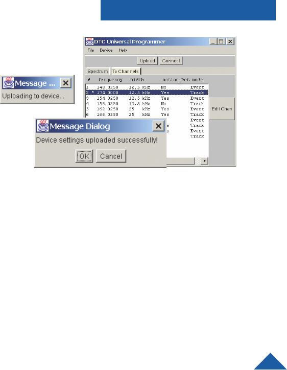
5
The programming software returns to the TX screen with your new
settings displayed, and an asterick (*) beside
the channel that has changed.
11 Click on the upload button.
A message screen displays the new settings
being uploaded to device.
A message screen displays that your settings
have been successfully uploaded.
Your new settings have been installed.
PROGRAMMING

486 Amherst Street • Nashua, New Hampshire 03063 • 603-880- 4411 www.dtccom.com