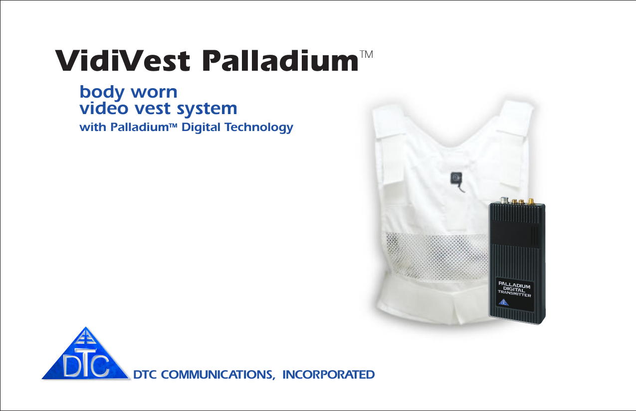
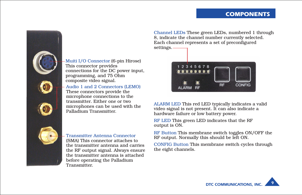
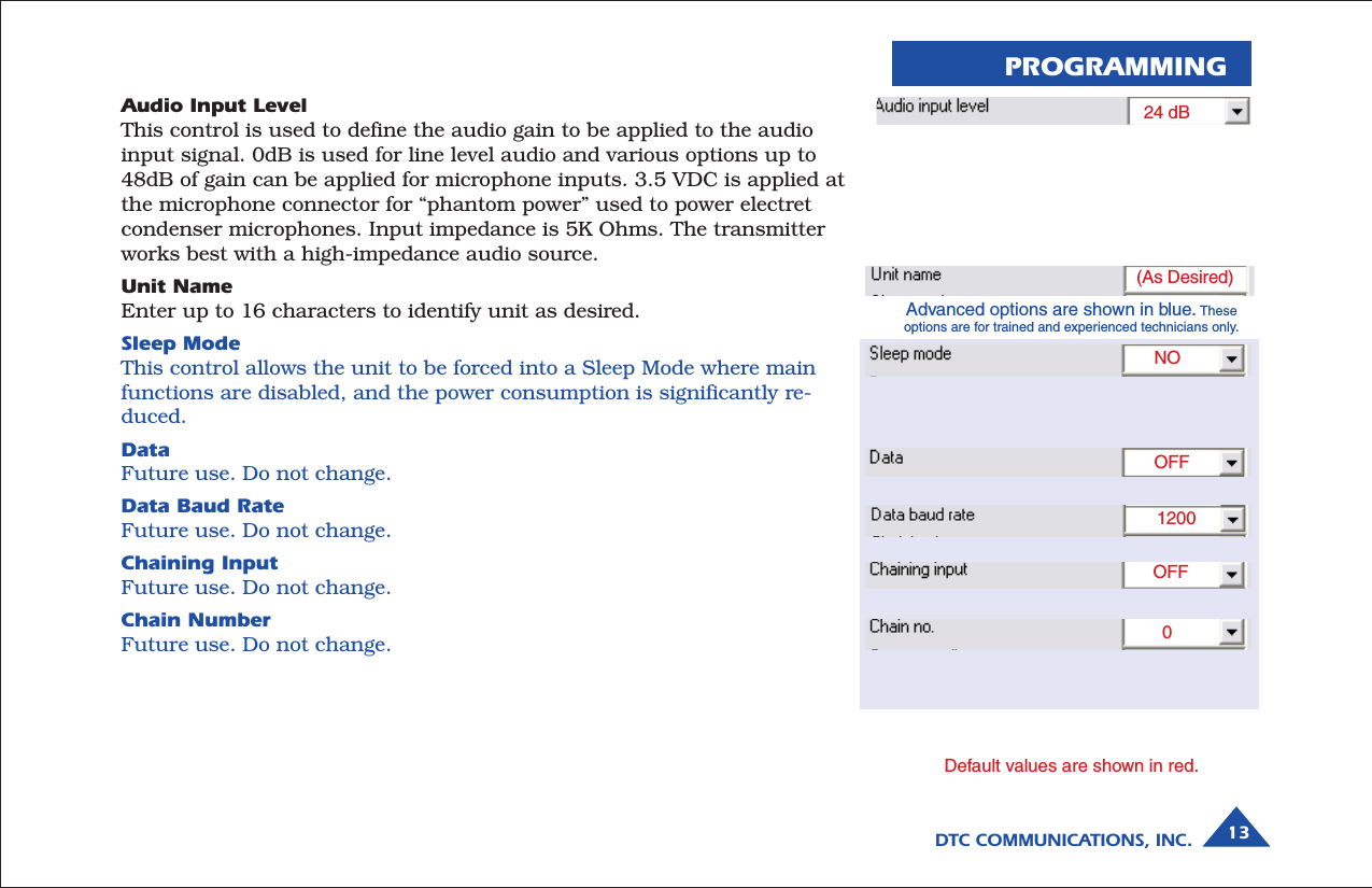
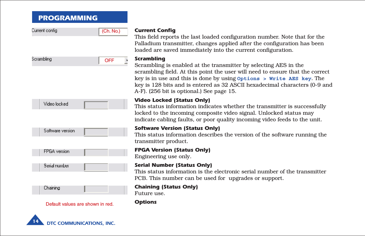
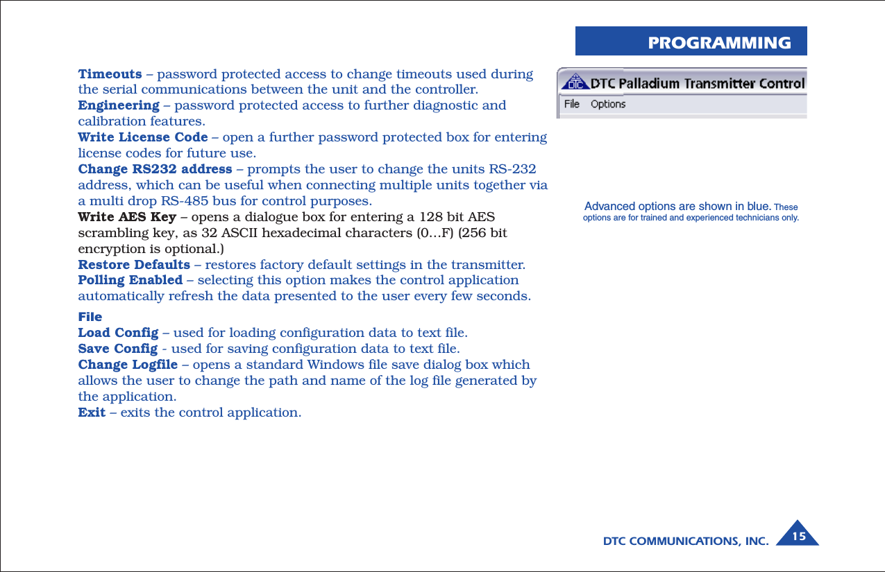
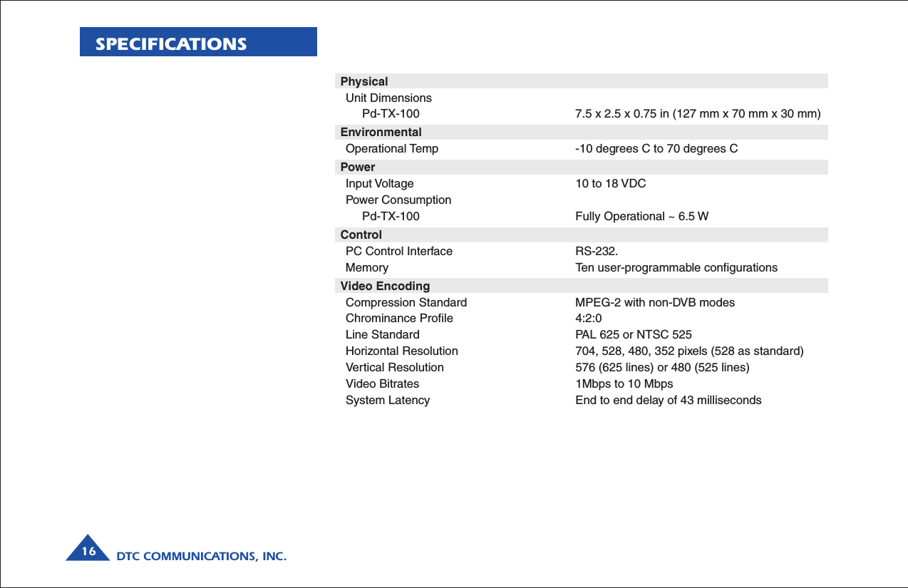
DTC Communications PDTX100SBW Digital Video Transmitter User Manual vidivest palladium9h

DTC Communications Inc. Digital Video Transmitter vidivest palladium9h

Manual

body wornvideo vest systemwith PalladiumTM Digital TechnologyDTC COMMUNICATIONS,  INCORPORATEDVidiVest PalladiumTM
DTC COMMUNICATIONS, INC.2warrantyDTC warrants its manufactured componentsagainst defects in material and workmanshipfor a period of two (2) years, commencing onthe date of original purchase.Products manufactured by others that areapproved for use with DTC equipment arewarranted for the manufacturer’s warrantyperiod, commencing from the date of shipmentfrom DTC.PN OP1920405 REV 1copyright noticeCopyright © 2005, 2006DTC Communications, Inc. All rightsreserved. No part of this document may bereproduced, transmitted, transcribed, storedin a retrieval system or translated into anylanguage or computer language, in any formor by any means, including but not limited toelectronic, magnetic, mechanical, optical,chemical, manual or otherwise, without theprior written permission of DTCCommunications, Inc.disclaimerThe information in the document is subject tochange without notice. DTC makes norepresentations or warranties with respect tothe contents hereof, and specifically disclaimsany implied warranties of merchantability orfitness for a particular purpose. DTC reservesthe right to revise this publication and tomake changes from time to time in thecontent hereof without obligation of DTC tonotify any person of such revision or changes.trademarksTrademarks of DTC Communications, Inc.include:• DTCTM• PalladiumTM• ArmorNetTM• SplitPIXTM• MiniPIXTM• DynaViewTMOther product names used in this manual arethe properties of their respective owners.how to contact DTCFor operator and troubleshooting information,customers are encouraged to refer to thedetails in this manual. For additionalclarification or instruction, or to order parts,contact DTC.Customer Service is available Monday throughFriday between the hours of 9:00 AM and5:00 PM EST at:Tel: 603-880-4411Fax: 603-880-6965Website: www.dtccom.comEmail: info@dtccom.com486 Amherst StreetNashua, New Hampshire 03063
DTC COMMUNICATIONS, INC. 3manual conventionsQuick Start ............................................................................ 4-5Overview ............................................................................... 6Components .......................................................................... 7- 9Programming ...................................................................... 10-15Specifications ..................................................................... 16-17Warranty ............................................................................. 18Contact DTC ............................................................................ 19TABLE OF CONTENTSNOTE: Describes special issues you shouldbe aware of while using a particular function.WARNING: Calls out situations in whichequipment could be damaged or a processcould be incorrectly implemented, but inwhich operator safety is not a factor.TIP: Describes application hints.RF EXPOSURE STATEMENTThe Vidivest Palladium has been tested to meetOccupational/Controlled exposure limits for BodywornDevices per FCC rules under Chapter 47, Part 2,Section 1093, paragraphs (b), (c), (d)(1), (d)(3) - LaboratoryTechnique, and (d)(4), by a certified testing laboratory.Information is available upon request.NOTE: This device is for occupational useonly. Occupational users are those personswho are exposed as a consequence of theiremployment, provided these persons are fullyaware of and exercise control over theirexposure.
DTC COMMUNICATIONS, INC.4QUICK START VidiVest PalladiumThe vest is shipped with all components installed and ready foruse. Be careful with the button camera when working on the rearpockets where most of the components are located. Setup the veston a clean, soft cloth on a tabletop for best results.1. Inspect the bottom rear pocket section of the vest. Make sureall connectors are secure as shown in the illustration (left).Connectors are keyed and color-coded.WARNING: Do not apply power to the transmitter unless anantenna or non-radiating load is connected to the AntennaSMA connector.Connections• Camera to Transmitter: 3-Pin to 3-Pin• Audio (if used): Two Lemo connectors (Push/Pull locking)• Power (Battery pack to TX): 2-Pin to 2-Pin• Antenna: SMA Male to TX SMA Connector2. Remove the battery holder by carefully releasing the locking connector.Each section of the battery holder has a cover, which must be removedwith a Phillips screwdriver to allow the batteries to be inserted orchanged.3. Install 9 NEW Lithium AA size batteries, observing proper polarity andreplace the screws for each section.4. The transmitter has been factory programmed to eight preset channels.Make sure the channel frequency selected matches the receiver’sfrequency. Slide the control panel door open (to the right). If you needto change the operating channel, press the CONFIG button to cyclethrough the 8 available channels indicated by the channel numberLEDs. Refer to the Programming section on page 10 for moreinformation on channel settings. When you change the channelconfiguration, the RF transmission is automatically switched OFF toprevent accidental interference.AUDIO  INPUT(S)BUTTON CAMERAFRONT PATCHANTENNAREAR PATCH ANTENNA9 AA  BATTERY  PACKSPLITTERVidiVest Palladium Wiring Diagram
DTC COMMUNICATIONS, INC. 5When you have selected the channel you need, push the RF button tostart transmitting again. The RF LED will turn ON. The transmitterRF should always be set to ON. The vest is deactivated bydisconnecting power.NOTE: The RF switch should remain ON during normal use. The RFautomatically shuts off during programming to prevent accidentaltransmissions on unintended frequencies. DO NOT HOLD THE RFBUTTON DOWN FOR MORE THAN ONE SECOND, or the unit will gointo sleep mode. In sleep mode, the unit is non-functional. Ifnecessary, recover from sleep mode by pressing and holding the RFbutton for more than two seconds.5. When power is applied, the transmitter will power-up to its last RFON/OFF state. Ensure that the green RF LED turns ON indicating theunit is transmitting.  If needed, push the RF button to begintransmitting.The channel number LED also turns ON, representing the most recentchannel setting from the last time the transmitter was used.6. Put the vest on (refer to photos page 6). Tighten the Velcro side straps sothat the system components are held closely to the body. The rear flapof the vest should be hanging loose.7. Orient the camera on the Velcro for a proper (right side up) picture.8. Put the shirt on over the vest. Button the camera through theappropriate buttonhole in the shirt. (See photos right.)9. Test the system. Verify the camera is properly positioned by looking atthe receiver’s monitor.  Walk quickly for a few steps, returning to themonitor.  Make sure the camera’s field of view has not changed.Reposition if necessary. Double-check the camera picture and anglebefore the mission.Your Transmitter is now operational. Confirm its signal with yourPalladium Receiver.NOTE: The red ALARM LED typically indicates no video input.It could also indicate a hardware failure or low battery power.Button CameraThe camera position can be adjusted todesired button hole.Casual ShirtQUICK START
DTC COMMUNICATIONS, INC.6OVERVIEWThe Palladium VidiVest Vest is a covert, body worn, 100 mW COFDMmicrowave video transmission garment system. Palladium digitaltechnology and our advanced antenna system combine to provide highsignal quality and very effective mobility. The vest conceals allcomponents and provides sheilding from transmitter heat. Power issupplied by a concealed 9 AA battery pack.The lightweight vest is designed to fit many body sizes and is ventilated forcomfort. It is designed to hold all system components as an undergarmentfor use with a casual shirt. The design holds all components close to thebody, allowing a loosely fitting shirt to be buttoned over it withoutprotrusions or wires showing. A hard-wired ON/OFF switch is available asan option. An optional wireless keyfob ON/OFF switch is also available.The high-resolution color CCD camera is disguised as a shirt button.The Palladium transmitter offers integral AES encryption.  Two audioinputs are provided.Deployment is quick and easy. All connectors are color-coded and locking.A special two-patch antenna harness, built into the vest, provides an omni-directional transmission pattern.  The entire vest system is powered from asingle battery pack, which holds 9 AA size Lithium batteries. A set ofNON-rechargeable Lithium cells have been provided in the kit. Battery lifewith one set of fresh Lithium cells is more than 3 hours.Note:  Only Lithium Ion AA batteries are recommended.The VidiVest Fits Snugly On The BodyUsing Velcro Fasteners.One size fits all.
DTC COMMUNICATIONS, INC. 7System Components•Vest – White with vents.Machine wash on gentle cyclewith detergent. Hang dry.• Transmitter – 100 mW, witheight programmable channels• Button Camera – Color, 5VDC• Antenna – Two-Patch systemwith Splitter• Two Audio Inputs• Battery Pack for 9AA batteries• Batteries – (Lithium aresupplied. The battery pack isshipped with batteriesinstalled)• Six buttons that match thebutton camera appearance• Operator Manual• Programming Software CDCOMPONENTSComponent PlacementVidiVest Palladium ComponentsFront BackOptionalMicrophone Patch Antenna Patch AntennaSplitterButtonCameraPalladiumTransmitter9 AABattery PackOptionalMicrophone
DTC COMMUNICATIONS, INC.8COMPONENTSTypical Palladium Operating TemperaturesA wide range of variables can affect the temperature of electronic devicesincluding ambient temperature, air flow, heat sink and mountingconsiderations.  In a typical test performed at room temperature, thePalladium 100 has been observed to have a baseplate operatingtemperature of 37oC (99oF). In other words, it can get warm. The VidiVestPalladium has a special heat shield between the transmitter chassis andthe user to provide comfort in entended missions or in warmenvironments. Be sure this is properly installed before each mission.Using your Palladium TransmitterFollow the instructions given in the Quick Start section on pages 4-5.When power is first applied to the Palladium, the unit reverts to the lastused channel and RF (ON/OFF) state. One of the green channel LEDs willturn ON indicating the active channel. If the video source (Camera) is notconnected, the ALARM LED will be ON.NOTE: Since the Palladium transmitter always returns to the lastconfiguration on power-up, the unit should always be deployed withthe RF switch ON. Therefore, once deployed, control of the unit mustbe restricted to applying and removing power. See the Quick Start(pages 4-5).Changing your Transmitter ConfigurationThe Palladium Transmitter can store up to 8 different configurations,which can be selected on the front panel. Each of these configurations canbe programmed into the Transmitter with the supplied DTC ProgrammingSoftware and a Windows PC. Refer to the Programming section on page 10for more information.To cycle through your preconfigured channels press the CONFIG buttononce to advance to the next setting. By default, the Palladium will turnOFF the transmitted signal while you are changing channels. This is toprevent accidental interference. Push the RF button after channel selectionto resume RF transmission of your video image.
DTC COMMUNICATIONS, INC. 9COMPONENTSAudio 1 and 2 Connectors (LEMO)These connectors provide themicrophone connections to thetransmitter. Either one or twomicrophones can be used with thePalladium Transmitter.Transmitter Antenna Connector(SMA) This connector attaches tothe transmitter antenna and carriesthe RF output signal. Always ensurethe transmitter antenna is attachedbefore operating the PalladiumTransmitter.Muiti I/O Connector (6-pin Hirose)This connector providesconnections for the DC power input,programming, and 75 Ohmcomposite video signal.ALARM LED This red LED typically indicates a validvideo signal is not present. It can also indicate ahardware failure or low battery power.RF LED This green LED indicates that the RFoutput is ON.RF Button This membrane switch toggles ON/OFF theRF output. Normally this should be left ON.CONFIG Button This membrane switch cycles throughthe eight channels.Channel LEDs These green LEDs, numbered 1 through8, indicate the channel number currently selected.Each channel represents a set of preconfiguredsettings.
DTC COMMUNICATIONS, INC.10PROGRAMMINGSystem PC Controller Application SoftwareAdvanced control of the system is available by using PC controlapplications. Typically users may want to customize the defaultconfigurations to control settings such as frequency, scrambling keys,modulation parameters, and video resolution.The transmitter is controlled by the application DTC_tx_ctrl.exeavailable on the CD delivered with the product.A PC is required with an open RS232 Serial COM port to configure atransmitter.Installation of the control program is as simple as copying it from the CDto a suitable location on the PC. No install shield routine is launched.Note that the application generates its own log and initializationfiles, so it is best to create a dedicated directory for theapplication, perhaps with a shortcut to the applicationfrom the desktop of the PC.AUDIO  INPUT(S)FRONT PATCHANTENNAREAR PATCH ANTENNASPLITTERPROGRAMMINGCABLETo PC Serial RS-232 PORT9 AA  BATTERY  PACKGetting Started• Use the supplied programmingcable to connect the chosen COMport of the PC to transmitter to beconfigured. Connect DC power.• Launch the application by doubleclicking or using the Start >Run... command.• Connection with a transmittershould be automatic, but the usercan force selection of the correctCOM port using the drop downport menu, followed by theConnect button.
DTC COMMUNICATIONS, INC. 11PROGRAMMINGTransmitter Control ApplicationOutput Frequency (MHz)The transmit frequency can be changed by entering the new desiredfrequency in this field. Values outside the range supported by a particulartransmitter type will be rounded to the highest or lowest supportedfrequency as appropriate. The resolution of the transmit frequency isresolved to the closest achievable within the supported step sizes of 1MHz,1.6667 MHz and 2.5 MHz.Modulation Output (same as RF button functionality)This control is used to turn on and off the RF output. After a configurationchange, the output always reverts to OFF. It must be ON for operation.Modulation FECThe default FEC is 2/3, however improved range operation can be achievedby selecting FEC 1/3. FEC 1/3 will improve signal range by 3dB. HoweverFEC 1/3 reduces link capacity to 1.2Mb/s.Modulation Guard IntervalThe Guard Interval is fixed at 1/16 in current firmware releases.Modulation BandwidthFor the Palladium transmitter products, the modulation bandwidth is fixedat 2.5MHz in current firmware release.COFDM ModeThe COFDM mode can be changed between QPSK and 16QAM. QPSK isthe default mode and will give the strongest most rugged RF linkperformance. Selecting 16QAM reduces the link performance by 5dB butimproves the link data throughput. Default values are shown in red.OFF2/31/162.5 MHzQPSK(your frequency)Advanced options are shown in blue. Theseoptions are for trained and experienced technicians only.
DTC COMMUNICATIONS, INC.12Output AttenuationThis control can be used to make minor adjustments to the output powerlevel, but in normal operation should not be changed from factory settings.(0 attenuation = full output power.)Video InputThis control is used to select the composite video input standard. Optionsare PAL, and NTSC both with and without 7.5 IRE pedestal.Video Bitrate (status only)The video bit rate is automatically maximized in each configuration whenChaining Input is turned off. This control can be used to set the videobitrate within the constraints of capacity available in the channel, but onlywhen Chaining Input is set to ON. Chaining CANNOT be enabled onnormal transmitters, and as such video bit rate control is automatic.Horizontal resolutionThe video coding resolution can be selected from 704, 528, 480 and 352pixels. For optimum performance, choose a resolution one step better thanyour camera’s resolution.Audio EncoderThe Audio can be turned ON and OFF with this control. Audio is OFF bydefault, but there are several audio modes that vary from very high qualityto speech grade that can be selected with this control. One or two channelaudio is supported. For optimum link performance, select the lowest audioquality necessary to support the mission.PROGRAMMING0NTSC1.1528OFFDefault values are shown in red.Advanced options are shown in blue. Theseoptions are for trained and experienced technicians only.
DTC COMMUNICATIONS, INC. 13Audio Input LevelThis control is used to define the audio gain to be applied to the audioinput signal. 0dB is used for line level audio and various options up to48dB of gain can be applied for microphone inputs. 3.5 VDC is applied atthe microphone connector for “phantom power” used to power electretcondenser microphones. Input impedance is 5K Ohms. The transmitterworks best with a high-impedance audio source.Unit NameEnter up to 16 characters to identify unit as desired.Sleep ModeThis control allows the unit to be forced into a Sleep Mode where mainfunctions are disabled, and the power consumption is significantly re-duced.DataFuture use. Do not change.Data Baud RateFuture use. Do not change.Chaining InputFuture use. Do not change.Chain NumberFuture use. Do not change.PROGRAMMING24 dB(As Desired)NOOFF1200OFF0Default values are shown in red.Advanced options are shown in blue. Theseoptions are for trained and experienced technicians only.
DTC COMMUNICATIONS, INC.14Current ConfigThis field reports the last loaded configuration number. Note that for thePalladium transmitter, changes applied after the configuration has beenloaded are saved immediately into the current configuration.ScramblingScrambling is enabled at the transmitter by selecting AES in thescrambling field. At this point the user will need to ensure that the correctkey is in use and this is done by using Options > Write AES key. Thekey is 128 bits and is entered as 32 ASCII hexadecimal characters (0-9 andA-F). (256 bit is optional.) See page 15.Video Locked (Status Only)This status information indicates whether the transmitter is successfullylocked to the incoming composite video signal. Unlocked status mayindicate cabling faults, or poor quality incoming video feeds to the unit.Software Version (Status Only)This status information describes the version of the software running thetransmitter product.FPGA Version (Status Only)Engineering use only.Serial Number (Status Only)This status information is the electronic serial number of the transmitterPCB. This number can be used for  upgrades or support.Chaining (Status Only)Future use.OptionsPROGRAMMING(Ch. No.)OFFDefault values are shown in red.
DTC COMMUNICATIONS, INC. 15Timeouts – password protected access to change timeouts used duringthe serial communications between the unit and the controller.Engineering – password protected access to further diagnostic andcalibration features.Write License Code – open a further password protected box for enteringlicense codes for future use.Change RS232 address – prompts the user to change the units RS-232address, which can be useful when connecting multiple units together viaa multi drop RS-485 bus for control purposes.Write AES Key – opens a dialogue box for entering a 128 bit AESscrambling key, as 32 ASCII hexadecimal characters (0…F) (256 bitencryption is optional.)Restore Defaults – restores factory default settings in the transmitter.Polling Enabled – selecting this option makes the control applicationautomatically refresh the data presented to the user every few seconds.FileLoad Config – used for loading configuration data to text file.Save Config - used for saving configuration data to text file.Change Logfile – opens a standard Windows file save dialog box whichallows the user to change the path and name of the log file generated bythe application.Exit – exits the control application.PROGRAMMINGAdvanced options are shown in blue. Theseoptions are for trained and experienced technicians only.
DTC COMMUNICATIONS, INC.16PhysicalUnit Dimensions     Pd-TX-100 7.5 x 2.5 x 0.75 in (127 mm x 70 mm x 30 mm)EnvironmentalOperational Temp -10 degrees C to 70 degrees CPowerInput Voltage 10 to 18 VDCPower Consumption     Pd-TX-100 Fully Operational ~ 6.5 WControlPC Control Interface RS-232.Memory Ten user-programmable configurationsVideo EncodingCompression Standard MPEG-2 with non-DVB modesChrominance Profile 4:2:0Line Standard PAL 625 or NTSC 525Horizontal Resolution 704, 528, 480, 352 pixels (528 as standard)Vertical Resolution 576 (625 lines) or 480 (525 lines)Video Bitrates 1Mbps to 10 MbpsSystem Latency End to end delay of 43 millisecondsSPECIFICATIONS
DTC COMMUNICATIONS, INC. 17SPECIFICATIONSAudio EncodingInput Stereo or Dual Mono pairBitrates 28 kbps to 72 kbps depending on configurationSampling Frequency 32 kHz, 16 kHz or 8kHzTHD < 0.1% maxResponse 20Hz to 13KHz, +/- 0.25dB depends on AudioEncoder settingCrosstalk > 55 dB minS/N 60 dB RMSComposite Video InputStandards NTSC (with and without pedestal) or PALSpecification Rec. ITU-R BT.470-4Connector HiroseComposite PAL and NTSC decoding Eight-bit comb filtering composite decoderAnalog AudioAnalog Audio Input +10 dBuNominal Level +4 dBuScramblingScrambling type Fixed key scrambling systemAlgorithms offered include AES.COFDM RF outputOutput Frequency Band DependentOccupied Bandwidth 2.44 MHzPower 100 mWConnector SMACOFDM Standard Proprietary, 2.5 MHz channel spacing, OFDMbandwidth of 2.44 MHz with 400 carriers.
             TWO YEAR WARRANTYDTC Communications, Inc. (DTC) warrants its RF transmitting and receiving products to be free fromdefects in workmanship or material for a period of two (2) years from the date of shipment unlessotherwise stated.The liability of DTC, Inc. under this warranty is limited to replacing, repairing, or issuing credit, atoption, for any products, which are returned by the purchaser during such warranty period, provided:DTC is notified and a Repair Authorization Number is issued by DTC Customer Service within 30 daysafter discovery of such defects by Customer.The defective units are returned to DTC with transportation charged Prepaid by the Customer.Product damaged in shipment must be reported to and claim forms filed with the Carrier by theCustomer.  In shipments to the factory, notice and claim procedures will be initiated by DTC.DTC’s examination of such products shall disclose to its satisfaction that such defects exist and havenot been caused by misuse, misapplication, neglect, improper installation, improper storage, alteration,physical damage or accidents.The warranty shall not apply to material or accessories ordinarily susceptible to field damage or of adisposable nature.  Examples include batteries, antennas, microphones, headsets, cases, accessorybags, etc. The warranty shall not apply to Engineering Prototypes or Customer requested modificationsto electronic circuits.This warranty does not apply to and DTC does not independently warrant items or systems sold by DTCwhich are produced by other manufacturers.  With respect to such items, the Customer shall look to thewarranty of the original manufacturer and DTC disclaims all warranty, expressed or implied.Nothing in this warranty, or any statement, brochure, bulletin, or advertisement is to be interpreted asestablishing the suitability of any product for particular application or use.  Applications of the productand the determination of suitability for any application, is the sole responsibility of the Customer.
CONTACT USDirectorState & Local Agencies & International SalesMichael  Demos(Nashua Main Office Numbers)direct voice (603) 546-2120cell (603) 320-3255mdemos@dtccom.comSales RepresentativesNashua Main Office Numbersvoice (603) 880-4411toll free (800) 233-8639fax (603) 880-6965Director of Federal SalesJohn Morgan(Nashua Main Office Numbers)direct voice (603) 546-2122cell (603) 320-3257jmorgan@dtccom.comInside SalesChristine Guzman(Nashua Main Office Numbers)direct voice (603) 546-2217cguzman@dtccom.comME, NH, VTOEM Sales ManagerRalph Descheneaux(Nashua Main Office Numbers)direct voice (603) 546-2119cell (603) 738-3627rdeschen@dtccom.comREGIONAL SALES MANAGERSHoward Richtoll free (888) 819-8570voice (860) 626-8570fax (860) 626-8571NY, MA, CT, RI, PA, NJ, MD, DE,WV, DChrich@dtccom.comGreg Langleyvoice (702) 236-0021fax (702) 293-6448WA, OR, ID, MT, ND, WY, SDglang46@aol.comGary Nicholstoll free (866) 794-2823voice (765) 473-8917fax (765) 473-8920MN, WI, MI, IA, MO, IL,IN, OH, KY, NEgnichols@dtccom.comFrank Priolitoll free (800) 246-2610voice (727) 392-4761fax (727) 320-0509FL, GA, AL, MS, TN, NC,SC, VAfprioli@dtccom.comJoe Parkinsontoll free (800) 952-4914voice (909) 598-5110fax (909) 598-3120CA, AZ, NV, UT, HI, AKjparkinson@dtccom.comEd Bryantvoice (903) 725-7229fax (903) 725-7863TX, OK, AR,LA, NM, KS, COebryant@dtccom.comCONTACT USFederal Sales ManagerWalter Patenaude(Nashua Main Office Numbers)direct voice (603) 546-2161cell (413) 454-3651wpatenaude@dtccom.comInternational Sales ManagerDana Crawford(Nashua Main Office Numbers)direct voice (603) 546-2110cell (508) 320-7225dcrawford@dtccom.com
486 Amherst Street • Nashua, New Hampshire 03063 • 603-880-4411www.dtccom.com

Navigation menu