DTC Communications PDTX5000 COFDM Transmitter User Manual 3
DTC Communications Inc. COFDM Transmitter 3
Manual
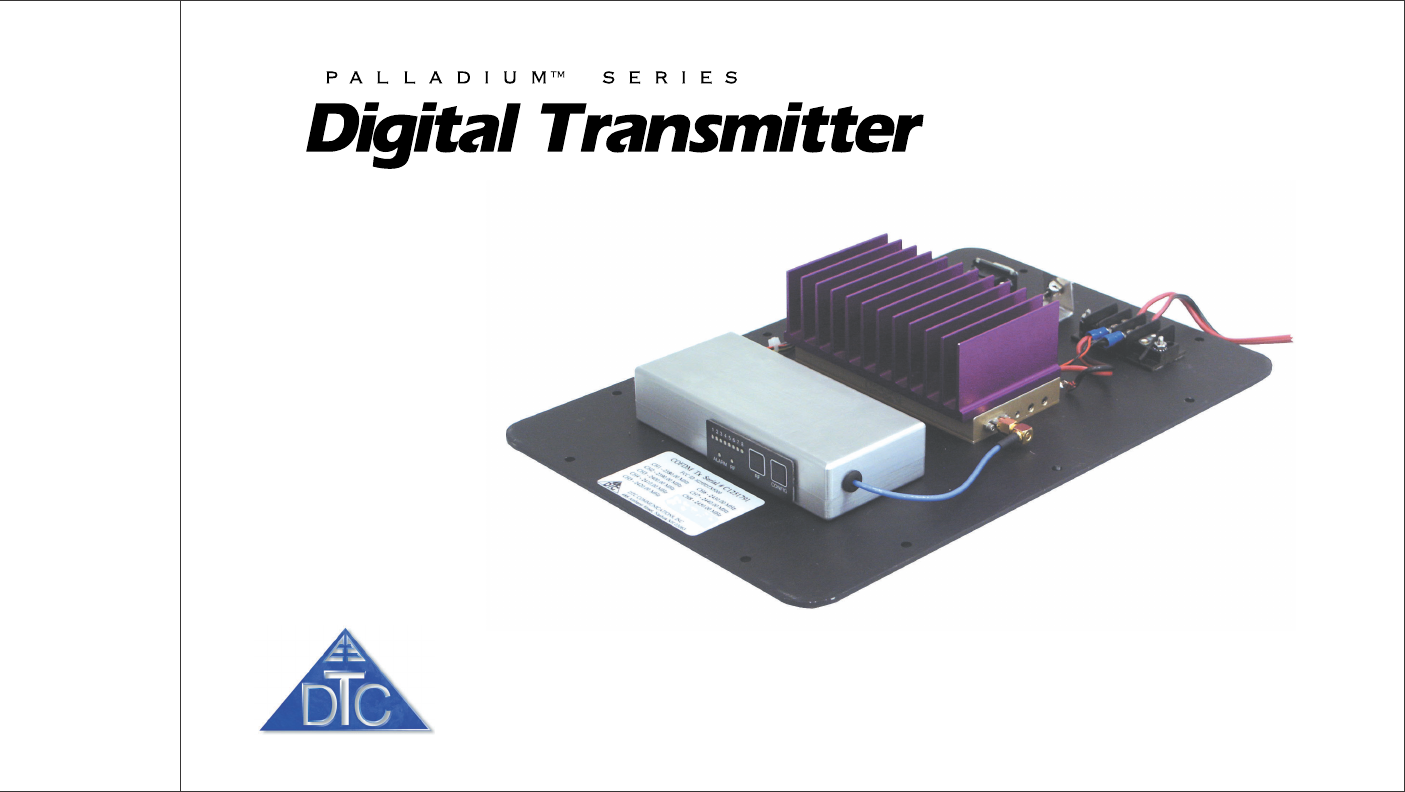
COFDM Transmitter Module
Model Pd-TX-1000 1 Watt Output
DTC COMMUNICATIONS, INCORPORATED

DTC COMMUNICATIONS, INC.
2
warranty
DTC warrants its manufactured components
against defects in material and workmanship
for a period of two (2) years, commencing on
the date of original purchase.
Products manufactured by others that are
approved for use with DTC equipment are
warranted for the manufacturer’s warranty
period, commencing from the date of shipment
from DTC.
FCC information
The following information is provided as a
service to our law enforcement customers who
require a Part 90 station license for video
surveillance operations using the 2450 to
2483.5 MHz band.
You will need to provide two documents:
• Form 600 (the application form)
• Form 159 (the filing fee form)
Forms can be obtained from the FCC on their
website at:
www.fcc.gov
You can also contact the FCC using their FAX
back service at: (888) 418-3676
Additional instructions are available by
telephone at: (888) 225-5322
The filing fee form is returned to:
Federal Communications Commission
1270 Fairfield Road
Gettysburg, PA 17325-7245
PN OP1920304 REV 1
copyright notice
Copyright © 2005
DTC Communications, Inc. All rights
reserved. No part of this document may be
reproduced, transmitted, transcribed, stored
in a retrieval system or translated into any
language or computer language, in any form
or by any means, including but not limited to
electronic, magnetic, mechanical, optical,
chemical, manual or otherwise, without the
prior written permission of DTC
Communications, Inc.
disclaimer
The information in the document is subject to
change without notice. DTC makes no
representations or warranties with respect to
the contents hereof, and specifically disclaims
any implied warranties of merchantability or
fitness for a particular purpose. DTC reserves
the right to revise this publication and to
make changes from time to time in the
content hereof without obligation of DTC to
notify any person of such revision or changes.
trademarks
Trademarks of DTC Communications, Inc.
include:
• DTC
• MiniPIX®
• DynaPIX®
Other product names used in this manual are
the properties of their respective owners.
how to contact DTC
For operator and troubleshooting information,
customers are encouraged to refer to the
details in this manual. For additional
clarification or instruction, or to order parts,
contact DTC.
Customer Service is available Monday through
Friday between the hours of 9:00 AM and
5:00 PM EST at:
Tel: 603-880-4411
Fax: 603-880-6965
Website: www.dtccom.com
Email: info@dtccom.com
486 Amherst Street
Nashua, New Hampshire 03063

DTC COMMUNICATIONS, INC. 3
NOTE: Describes special issues you should
be aware of while using a particular function.
WARNING: Calls out situations in which
equipment could be damaged or a process
could be incorrectly implemented, but in
which operator safety is not a factor.
TIP: Describes application hints.
manual conventions Quick Start ............................................................................ 4-5
Complete These Steps ................................................................ 4
Thermal Issues ........................................................................... 4
Introduction ............................................................................... 6
Operation ............................................................................... 7
Using your Palladium Transmitter ................................................ 7
Changing your Transmitter Configuration .................................... 7
Components ........................................................................... 8-9
Programming ...................................................................... 10-15
System PC Controller Application Software .............................. 10
Getting Started .......................................................................... 10
Transmitter Control Application ................................................. 11
Specifications ..................................................................... 16-17
Warranty ............................................................................. 18
Contact Us ............................................................................. 19
TABLE OF CONTENTS
DTC COMMUNICATIONS, INC.
4
1
2
3
QUICK START
Palladium Transmitter
1Connect the transmitter antenna to the SMA connector on the
Palladium unit (see photo left).
2Attach a 12 VDC power source (such as a battery pack or AC power
adapter) to the power block as shown below. The input voltage range is
from 10 to 18 VDC.
NOTE: Device is polarity sensitive. Connect DC power only as shown
below; black to black (-), red to red (+).
3Attach your camera video input (75 ohm composite video source in PAL
or NTSC) to the video RCA connector (see photo below).
4Apply the necessary power to your camera and turn ON.
Complete these steps:
Programming
Connector
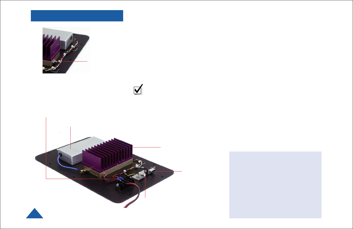
Thermal Issues
Palladium TX-1000
Modules feature a heat sink
for proper heat dissipation.
For optimal performance, do
not block air flow over the
fins of this heat sink.
Heat Sink
DTC COMMUNICATIONS, INC. 5
56
QUICK START
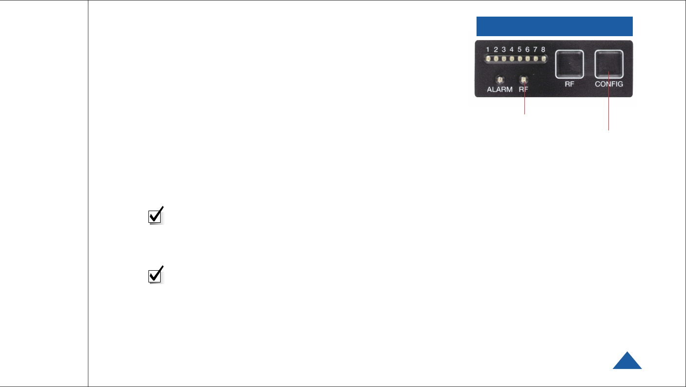
5When power is applied, the green RF LED turns ON. The channel
number LED also turns ON, representing the most recent channel
setting from the last time the transmitter was used. Push the RF button
to transmit.
6 If you need to change the operating channel, press the CONFIG button
to cycle through the 8 available channels indicated by the channel
number LEDs. Refer to the Programming section on page 10 for more
information on channel settings. When you change the channel
configuration, the RF transmission is automatically switched OFF to
prevent accidental interference. When you have selected the channel
you need, push the RF button for one second to start transmitting
again. The RF LED will turn ON.
NOTE: A red ALARM LED indicates that no video is connected.
Your Transmitter is now operational. Confirm its signal with your
Palladium Receiver.
Palladium TX-1000 Transmitter Controls
NOTE: Eight Channel LEDs are located on the control panel.
If all 8 green LEDs are flashing, this indicates that your battery
source is low.

DTC COMMUNICATIONS, INC.
6
INTRODUCTION
The Palladium Series of digital video transmitters provide exceptional video
quality in high multipath environments. They are ideal for use inside
buildings, in urban areas, and in other applications where multipath
would normally cause video tearing or breakup.
All Palladium Series transmitters are designed for spectrum-efficient 2.5
MHz channel spacing. Approximately 400 carriers are used to transmit
video and two channels of voice and data. Palladium transmitters may be
located on adjacent channels without a guard band. AES 128-bit
encryption ensures users of secure communications.
The Palladium 1000 is a small, modular transmitter with a 1W RF power
output. It’s ideal for OEM concealments and short to mid-range robotic
and UAV applications. The package is only 13” x 9” x 2.5”. Power consump-
tion is 6 Watts. All connections are conveniently located. This device can be
powered with disposable batteries. The Palladium 1000 incorporates a
power amplifier bringing total power output to 1W.
Palladium TX-1000
1 Watt Digital Transmitter
NOTE: Use only Lithium batteries with this device.

DTC COMMUNICATIONS, INC. 7
OPERATION
Using your Palladium Transmitter
Follow the instructions given in the Quick Start section on pages 4-5.
When power is first applied to the Palladium, the unit reverts to the last
used channel and RF is turned ON. One of the green channel LEDs will
turn ON indicating the active channel. The Alarm LED may be ON, which
indicates that there is no active video input.
Changing your Transmitter Configuration
The Palladium Transmitter can store up to 8 different configurations,
which can be selected on the front panel. Each of these configurations can
be programmed into the Transmitter with the supplied DTC Programming
Software and a Windows PC. Refer to the Programming section on page 10
for more information.
To cycle through your preconfigured channels press the CONFIG button
once to advance to the next setting. By default, the Palladium will turn
OFF the transmitted signal while you are changing channels. This is to
prevent accidental interference. Push the RF button after channel selection
to resume RF transmission of your video image.
To place your Palladium Transmitter in (low current consumption) standby
mode, hold the RF button for one second. The RF LED turns OFF
indicating the TX is now in standby mode. Push RF again to resume
transmitting.
Palladium TX-1000
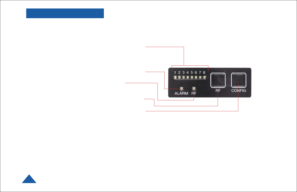
Transmitter Control Panel
DTC COMMUNICATIONS, INC.
8
COMPONENTS
ALARM LED This red LED indicates a valid video signal
is not present.
RF LED This green LED indicates that the RF
output is ON.
RF Button This membrane switch toggles ON/OFF the
RF output.
CONFIG Button This membrane switch cycles through
the eight channels.
Channel LEDs These green LEDs, numbered 1 through
8, indicate the channel number currently selected.
Each channel represents a set of preconfigured
settings.
Transmitter Control Panel
DTC COMMUNICATIONS, INC. 9
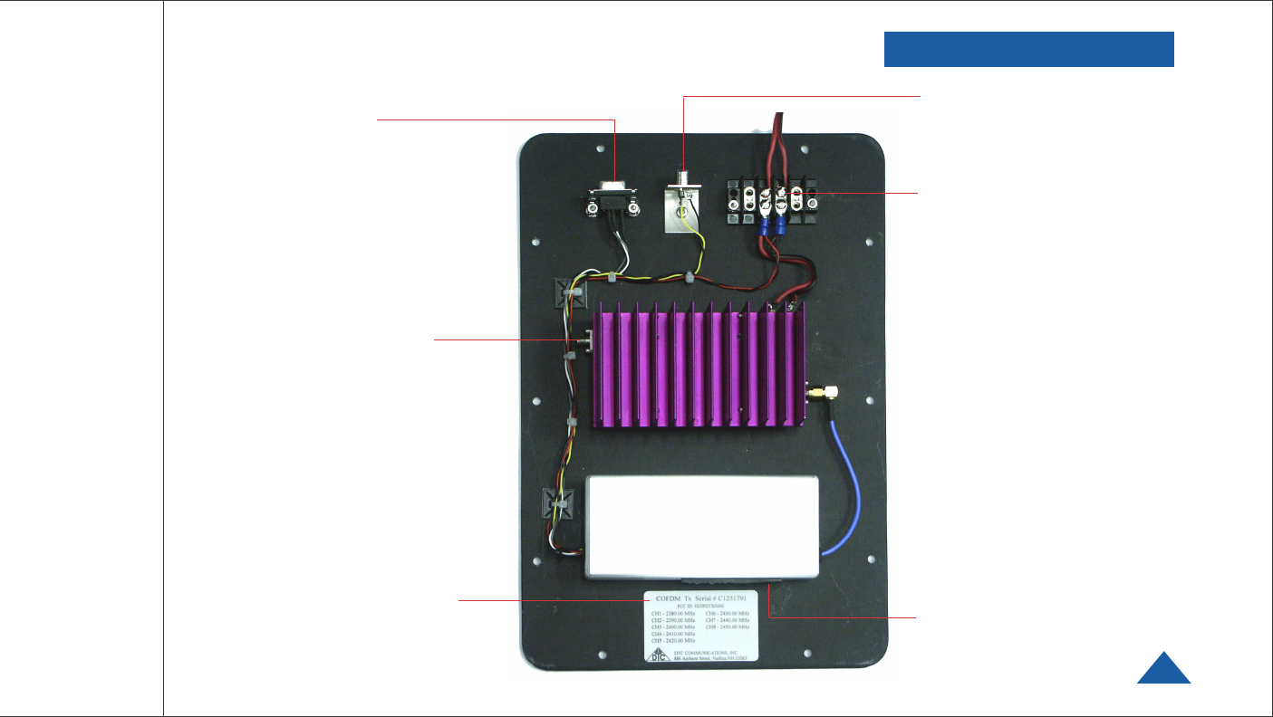
COMPONENTS
FCC ID Label This label
identifies the frequencies
programmed into the
Palladium Transmitter.
Transmitter Antenna
Connector (SMA) This
connector attaches to the
transmitter antenna and
carries the RF output
signal. Always ensure the
transmitter antenna is
attached before operating
the Palladium Transmitter.
Programming
Connector
(DB-9) See Page 10.
DC Power Input
10-18 VDC
Video Input Connector
75 Ohm Composite Video
Signal
Control Panel
See Page 8.

DTC COMMUNICATIONS, INC.
10
PROGRAMMING
System PC Controller Application Software
Advanced control of the system is available by using PC control applica-
tions. Typically users may want to customize the default configurations to
control settings such as frequency, scrambling keys, modulation
parameters, and video resolution.
The transmitter is controlled by the application DTC_tx_ctrl.exe avail-
able on the CD delivered with the product.
A PC is required with two RS232 Serial COM ports to control both a
transmitter and receiver simultaneously. Where changes are to be made to
either a transmitter, or a receiver, at different times, a PC with a single
RS232 Serial COM part can be used.
Installation of the two control programs is as simple as copying them from
the CD to a suitable location on the PC. No install shield routine is
launched. Note that the controllers generate their own log and
initialization files, so it is best to create a dedicated directory for these
applications, perhaps with links to the applications from the desktop of
the PC.
Getting Started
•Use the supplied cables to connect the chosen COM port(s) of the PC to
unit(s) to be configured.
•Launch each application in turn by double clicking or using the run
command.
•Connection with a transmitter should be automatic, but the user can
force selection of the correct COM port using the drop down, followed by
the Connect button.
•Errors may appear during the connection process if the PC is unable to
automatically ascertain which unit is connected to which COM port.

DTC COMMUNICATIONS, INC. 11
PROGRAMMING
Transmitter Control Application
Output Frequency (MHz)
The transmit frequency can be changed by entering the new desired
frequency in this field. Values outside the range supported by a particular
transmitter type will be rounded to the highest or lowest supported
frequency as appropriate. The resolution of the transmit frequency is
complex and resolved to the closest achievable within the constants of the
supported step sizes of 1MHz, 1.6667 MHz and 2.5 MHz.
Modulation Output
This control is used to turn on and off the RF output. After a configuration
change, the output always reverts to OFF. It must be ON for operation.
Modulation FEC
The default FEC is 2/3, however improved range operation can be achieved
by selecting FEC 1/3. FEC 1/3 will improve signal range by 3dB. However
FEC 1/3 reduces link capacity to 1.2Mb/s therefore reducing picture
quality.
FEC Link Bitrate Sensitivity 2/3 2.4Mb/s: -99dBm,
1/3 1.2Mb/s: -102dBm
Modulation Guard Interval
The Guard Interval is fixed at 1/16 in current software releases.
Modulation Bandwidth
For the Palladium transmitter products, the modulation bandwidth is fixed
at 2.5MHz.
COFDM Mode
The COFDM mode can be changed between QPSK and 16QAM. QPSK is
the default mode and will give the strongest most rugged RF link
performance. Selecting 16QAM reduces the link performance by 5dB but
improves the link data throughput, giving significantly better video quality.
DTC COMMUNICATIONS, INC.
12
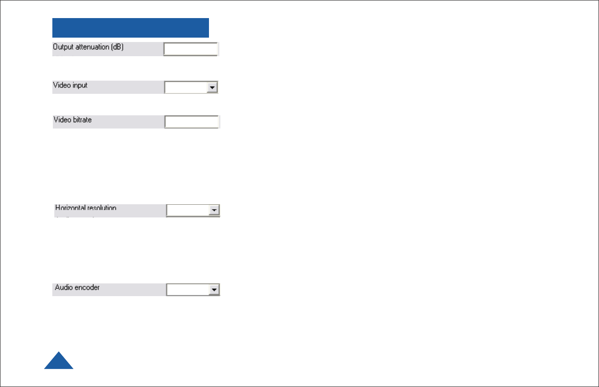
Output Attenuation
This control can be used to make minor adjustments to the output power
level, but in normal operation should not be changed from factory settings.
Video Input
This control is used to select the composite video input standard. Options
are PAL, and NTSC both with and without 7.5 IRE pedestal.
Video Bitrate
This control can be used to set the video bitrate within the constraints of
capacity available in the channel, but only when Chaining Input is set to
ON.
Chaining CANNOT be enabled on normal transmitters, and as such video
bit rate control is automatic.
The video bit rate is automatically maximized in each configuration when
Chaining Input is turned off.
Horizontal resolution
The video coding resolution can be selected from 704, 528, 480 and 352
pixels. Changing the horizontal resolution to lower values will make the
coded picture softer.
Care should be taken to match the horizontal resolution to the resolution
of the camera connected to the transmitter; this will give best image
results.
Audio Encoder
The Audio can be turned on and off with this control. Audio is OFF by
default, but there are several audio modes that vary from very high quality
to speech grade that can be selected with this control. Enabling audio will
degrade the video quality, because some of the available data capacity is
diverted away from video to audio. Selecting high fidelity audio modes will
degrade the video quality more than lower fidelity audio modes.
PROGRAMMING

DTC COMMUNICATIONS, INC. 13
Audio Input Level
This control is used to define the audio gain to be applied to the audio
input signal. 0dB is used for line level audio and various options up to
48dB of gain can be applied for microphone inputs.
Unit Name
Can be user defined. Type in name.
Sleep Mode
This control allows the unit to be forced into a Sleep Mode where
main functions are disabled, and the power consumption is significantly
reduced.
Data
Future use.
Data Baud Rate
Future use.
Chaining Input
Future use.
Chain Number
Future use.
PROGRAMMING

DTC COMMUNICATIONS, INC.
14
Current Config
This field reports the last loaded configuration number. Note that for the
Palladium transmitter, changes applied after the configuration has been
loaded are saved immediately into the current configuration.
Scrambling
Scrambling must be enabled at the transmitter by selecting AES in the
scrambling field. At this point the user will need to ensure that the correct
key is in use and this is done by using Options/Write AES key. The key is
128 bits and is entered as 32 ASCII hexadecimal characters (0-9 and A-F).
Video Locked (Status Only)
This status information indicates whether the transmitter is successfully
locked to the incoming composite video signal. Unlocked status may
indicate cabling faults, or poor quality incoming video feeds to the unit.
Software Version (Status Only)
This status information describes the version of the software running the
transmitter product.
FPGA Version (Status Only)
Engineering use only.
Serial Number (Status Only)
This status information is the electronic serial number of the transmitter
PCB. This number can be used for upgrades or support.
Chaining (Status Only)
Future use.
PROGRAMMING

DTC COMMUNICATIONS, INC. 15
Options
Timeouts – password protected access to change timeouts used during
the serial communications between the unit and the controller.
Engineering – password protected access to further diagnostic and
calibration features.
Write License Code – open a further password protected box for entering
license codes for future use.
Change RS232 address – prompts the user to change the units RS-232
address, which can be useful when connecting multiple units together via
a multi drop RS-485 bus for control purposes.
Write AES Key – opens a dialogue box for entering a 128bit AES
scrambling key, as 32 ASCII hexadecimal characters (0…F)
Restore Defaults – restores factory default settings in the transmitter.
Polling Enabled – selecting this option makes the control application
automatically refresh the data presented to the user every few seconds.
File
Load Config – used for loading configuration data to text file.
Save Config - used for saving configuration data to text file.
Change Logfile – opens a standard Windows file save dialog box which
allows the user to change the path and name of the log file generated by
the application.
Exit – exits the control application.
PROGRAMMING

DTC COMMUNICATIONS, INC.
16
Physical
Unit Dimensions
Pd-TX-1000 14 x 9 x 3.5 in (356 mm x 229 mm x 89 mm)
Environmental
Operational Temp with Heatsink -10 degrees C to 70 degrees C
Ambient Temp with Heatsink -10 degrees C to 40 degrees C
Power
Input Voltage 10 to 18 VDC
Power Consumption
Pd-TX-1000 Fully Operational ~ 2 W, Sleep Mode < 0.5 W
Control
PC Control Interface RS-232.
Memory Ten user-programmable configurations
Video Encoding
Compression Standard MPEG-2 with non-DVB modes
Chrominance Profile 4:2:0
Line Standard PAL 625 or NTSC 525
Horizontal Resolution 704, 528, 480, 352 pixels (528 as standard)
Vertical Resolution 576 (625 lines) or 480 (525 lines)
Video Bitrates 1Mbps to 10 Mbps
System Latency End to end delay of 43 milliseconds
SPECIFICATIONS

DTC COMMUNICATIONS, INC. 17
SPECIFICATIONS
Audio Encoding
Input 1 Stereo or Dual Mono pair
Bitrates 7 28 kbps to 72 kbps depending on configuration
Sampling Frequency 32 kHz, 16 kHz or 8kHz
THD < 0.1% max
Response 20Hz to 6KHz, +/- 0.25dB
Crosstalk > 55 dB min
S/N 60 dB RMS
Composite Video Input
Standards NTSC (with and without pedestal) or PAL
Specification Rec. ITU-R BT.470-4
Connector Hirose
Composite PAL and NTSC decoding Eight-bit comb filtering composite decoder
Analog Audio
Analog Audio Input +10 dBu
Nominal Level +4 dBu
Data
Baud Rate Up to 115 kbaud
Connector LEMO
Scrambling
Scrambling type Fixed key scrambling system
Algorithms offered include AES.
COFDM RF output
Output Frequency Band Dependent
Occupied Bandwidth 2.5 MHz
Power 100 mW or 250 mW
Connector SMA
COFDM Standard Proprietary, 2.5 MHz channel spacing, OFDM
bandwidth of 2.44 MHz with 400 carriers.

DTC COMMUNICATIONS, INC.
18
TWO YEAR WARRANTY
DTC Communications, Inc. (DTC) warrants its RF transmitting and receiving products to be free from
defects in workmanship or material for a period of two (2) years from the date of shipment unless
otherwise stated.
The liability of DTC, Inc. under this warranty is limited to replacing, repairing, or issuing credit, at
option, for any products, which are returned by the purchaser during such warranty period, provided:
DTC is notified and a Repair Authorization Number is issued by DTC Customer Service within 30 days
after discovery of such defects by Customer.
The defective units are returned to DTC with transportation charged Prepaid by the Customer.
Product damaged in shipment must be reported to and claim forms filed with the Carrier by the
Customer. In shipments to the factory, notice and claim procedures will be initiated by DTC.
DTC’s examination of such products shall disclose to its satisfaction that such defects exist and have
not been caused by misuse, misapplication, neglect, improper installation, improper storage, alteration,
physical damage or accidents.
The warranty shall not apply to microphones, batteries, antennas, crystals or material ordinarily
susceptible to field damage or any accessories of a disposable nature. The warranty shall not apply to
Engineering Prototypes or Customer requested modifications to electronic circuits.
This warranty does not apply to and DTC does not independently warrant items or systems sold by DTC
which are produced by other manufacturers. With respect to such items, the Customer shall look to the
warranty of the original manufacturer and DTC disclaims all warranty, expressed or implied.
Nothing in this warranty, or any statement, brochure, bulletin, or advertisement is to be interpreted as
establishing the suitability of any product for particular application or use. Applications of the product
and the determination of suitability for any application, is the sole responsibility of the Customer.

DTC COMMUNICATIONS, INC. 19
CONTACT US
Director
State & Local Agencies & International Sales
Michael Demos
(Nashua Main Office Numbers)
direct voice (603) 546-2120
cell (603) 320-3255
mdemos@dtccom.com
OEM Sales Manager
Steve Chisholm
(Nashua Main Office Numbers)
direct voice (603) 546-2124
schisholm@dtccom.com
State/Local Inside Sales
Karen Korza
(Nashua Main Office Numbers)
direct voice (603) 546-2169
kkorza@dtccom.com
Sales Representatives
Nashua Main Office Numbers
voice (603) 880-4411
toll free (800) 233-8639
fax (603) 880-6965
Director of Federal Sales
John Morgan
(Nashua Main Office Numbers)
direct voice (603) 546-2122
cell (603) 320-3257
jmorgan@dtccom.com
Federal Sales Manager
Marianne Caiazza
(Nashua Main Office Numbers)
direct voice (603) 546-2121
cell (603) 320-3256
mcaiazza@dtccom.com
Federal Sales Manager
Walter Patenaude
(Nashua Main Office Numbers)
direct voice (603) 546-2161
cell (413) 454-3651
wpatenaude@dtccom.com
Federal/International/OEM Inside Sales
Christine Guzman
(Nashua Main Office Numbers)
direct voice (603) 546-2217
cguzman@dtccom.com
Surveillance Platforms
IST
toll free (888) 478-6599
voice (954) 755-0724
cell (954) 755-0817
teamist@aol.com
Canada
Dyplex Communications Ltd.
Gary Sayer
voice (416) 675-2002
fax (416) 675-1822
info@dyplex.com
REGIONAL SALES MANAGERS
Howard Rich
toll free (888) 819-8570
voice (860) 626-8570
fax (860) 626-8571
NY, MA, CT, RI, PA, NJ, MD, DE,
WV, DC
hrich@dtccom.com
Floyd Flowers
voice (208) 667-5197
fax (208) 676-8107
WA, OR, ID, MT, ND, WY, UT, SD
Gary Nichols
toll free (866) 794-2823
voice (765) 473-8917
fax (765) 473-8920
MN, WI, MI, IA, MO, IL,
IN, OH, KY, NE
gnichols@dtccom.com
Frank Prioli
toll free (800) 246-2610
voice (727) 392-4761
fax (727) 320-0509
FL, GA, AL, MS, TN, NC,
SC, VA
fprioli@dtccom.com
Joe Parkinson
toll free (800) 952-4914
voice (909) 598-5110
fax (909) 598-3120
CA, AZ, NV, HI, AK
jparkinson@dtccom.com
Ed Bryant
voice (903) 725-7229
fax (903) 725-7863
ME, NH, VT,TX, OK, AR,
LA, NM, KS, CO
ebryant@dtccom.com

486 Amherst Street • Nashua, New Hampshire 03063 • 603-880-4411
www.dtccom.com