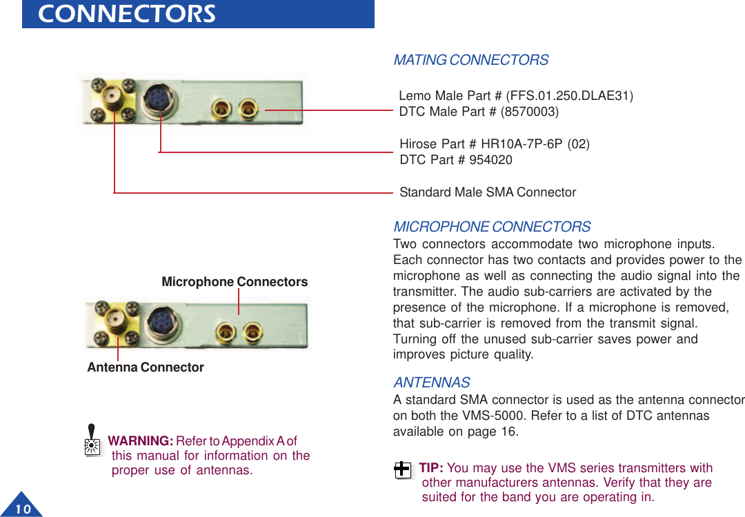
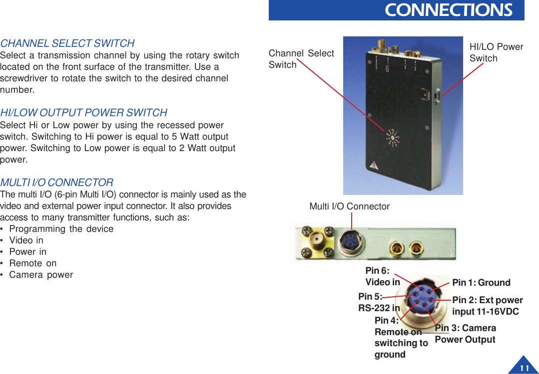
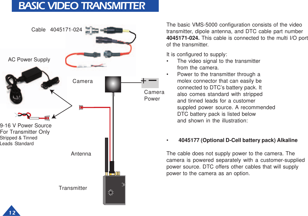
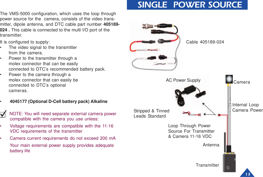
DTC Communications VMS5000 VMS-5000 Video Transmitter User Manual 2 Watt

DTC Communications Inc. VMS-5000 Video Transmitter 2 Watt

Revised Manual

DTC COMMUNICATIONS INCORPORATEDSwitch SelectableSwitch SelectableSwitch SelectableSwitch SelectableSwitch Selectable5W - 2W5W - 2W5W - 2W5W - 2W5W - 2WVVVVVideo Tideo Tideo Tideo Tideo TransmitterransmitterransmitterransmitterransmitterSwitch SelectableSwitch SelectableSwitch SelectableSwitch SelectableSwitch Selectable5W - 2W5W - 2W5W - 2W5W - 2W5W - 2WVVVVVideo Tideo Tideo Tideo Tideo TransmitterransmitterransmitterransmitterransmitterVMS-5000 Frequency 2450-2500 MHz
How to contact DTCFor operator and troubleshootinginformation, customers are encouraged to refer tothe details in this manual. For additionalclarification or instruction, or to order parts,contact DTC.Customer Service is available Monday throughFriday between the hours of 9:00 AM and5:00 PM EST at:Tel: 603-880-4411Fax: 603-880-6965Website: www.dtccom.comEmail: info@dtccom.com486 Amherst StreetNashua, New Hampshire 03063USACopyright NoticeCopyright © 2003DTC Communications, Inc. All rightsreserved. No part of this document may bereproduced, transmitted, transcribed, stored in a re-trieval system or translated into anylanguage or computer language, in any form or byany means, including but not limited to electronic,magnetic, mechanical, optical, chemical, manual orotherwise, without the prior written permission ofDTC Communications, Inc.DisclaimerThe information in the document is subject to changewithout notice. DTC makes no representations orwarranties with respect to the contents hereof, andspecifically disclaims any implied warranties of mer-chantability or fitness for a particular purpose. DTCreserves the right to revise this publication and tomake changes from time to time in the content hereofwithout obligation of DTC to notify any person of suchrevision or changes.TrademarksTrademarks of DTC Communications, Inc. include:• DTC• MiniPIX®• DynaPIX®Other product names used in this manual are theproperties of their respective owners.WarrantyDTC warrants its manufactured components againstdefects in material and workmanship for a period oftwo (2) years, commencing on the date of originalpurchase.Products manufactured by others that are approvedfor use with DTC equipment are warranted for themanufacturer’s warranty period, commencing fromthe date of shipment from DTC.FCC informationForms can be obtained from the FCC on their web-site at:www.fcc.govYou can also contact the FCC using their FAX backservice at: (888) 418-3676Additional instructions are available by telephone at:(888) 225-5322The filing fee form is returned to:Federal Communications Commission1270 Fairfield RoadGettysburg, PA 17325-72452           OP1920187 Rev A
3  TABLE OF CONTENTSKit Contents ......................................................................... 4Quick Start ............................................................................ 5Encryption ............................................................................ 6Heat Considerations ........................................................... 7Mounting Options ................................................................ 8Reinstalling Heatsink .......................................................... 9Connectors ........................................................................ 10Connections ...................................................................... 11Basic Video Transmitter .................................................... 12Single Power Source......................................................... 13Components ................................................................ 14-16Programming ............................................................... 17-20Specifications ............................................................... 21-23Features ............................................................................ 24Warranty ............................................................................. 25Appendix A. Antenna Safety................................................ 26Manual ConventionsNOTE Describes special issues you should be aware ofwhile using a particular function.WARNING Calls out situations in which equipment couldbe damaged or a process could be incorrectly imple-mented, but in which operator safety is not a factor.TIP Describes application hints.RF EXPOSURE STATEMENTThis product is NOT recommended for use in body-wornapplications.  Refer to Appendix A in this manual for instruc-tion in the proper use of antennas with this device. When inuse a seperation distance of at least 20 cm must bemaintained between the supplied antenna and the body ofthe user or nearby persons. At this distance the field densitywill be 1.61 mW/cm2, well below the maximum permissableexposure level of 5. mW/cm2.Note: This device is for occupational use only. Occupa-tional users are those persons who are exposed as aconsequence of their employment, provided thesepersons are fully aware of and exercise control overtheir exposure. See Appendix A. Antenna Safety.FCC ID# H25VMS5000
4TYPICAL KITNOTE: The dipole antenna included is not recom-mended for normal use! This antenna enables you toquickly set up your transmitter and ensure properoperation.  DTC highly recommends the use ofcircularly polarized antennas for the best rejection ofmulti-path.NOTE: DTC has provided you with a “Y” cable (powerand video) terminated with an RCA connector and aBNC adapter for your convenience.2W-5W Video Transmitterwith HeatsinkAdapterRCA(F) to RCA(F)ProgrammingCable withPower AdapterAC 100-240VPower Adapterwith Molex ConnectorMulti I/O Cablefor TransmitterPower, CameraPower and VideoCable forCamera Power2.1mm to MolexScrewdriverAntenna(ANT-VIX)Included with your 5 Watt -2 Watt Transmitter:• VMS-5000 Video Transmitter packaged in case with   heatsink attached• Accessories kit containing:• DTC programming software package• DTC programming cable• Camera Cable• Dipole antenna with right angle SMA connector• Video and Power In “Y” cable• Four captive mounting screws• Transmitter mounting bracket (optional)
5QUICK START1Make sure that  the external power source to the      transmitter is OFF.2Using a screwdriver, turn the channel selector to thecorrect channel number.3Connect an antenna to the ANTENNA connector on themodule.4Select Hi or Lo Power using the recessed switch.5Connect the microphone or microphones to the MIC-1and MIC-2 connectors on the module.6Connect a video source and external power (11 -16 VDC)to the Video/Multi-I/O connector.7   If you are using an (optional) Encryption model, choose     Encrypted (SCR) or Clear (CLR) as desired8Apply power to the transmitter.Warning: Do not apply power to the transmitter until anantenna has been connected in step 3.235467
6ScrewsScrewsTransmitterHeatsinkEncryptionSide ViewHeatsink,Transmitter,and EncryptionENCRYPTION OPTIONCLR SCR .33SCRAMBLER1.184Top View As an option, the transmitter can be equipped with anencryption module with a two position switch. In the CLR(clear) mode, clear analog microwave video is transmitted. Inthe SCR (scrambled) mode, the video will be scrambledand capable of being decoded by a compatible receiver only.Note: The scrambled transmission mode is recom-mended. Casual scanners will not be able to decode thesignal and see what is being transmitted.SCR position = ON, CLR position is OFF
7HEAT CONSIDERATIONSNOTE: NEVER remove the heatsink.NOTE: HOT SURFACE MAY CAUSE BURNS. Ensurethat transmitter is properly ventilated and allow to coolbefore touching.Heat is an enemy of electronic components so it is impera-tive that the transmitter is not allowed to exceed 80 degreesC. With the heatsink removed, the temperature would rise to125 degrees C or more, which would be destructive to theinternal components. At 125 degrees C, the unit would alsodeliver a serious burn if touched.Much of the heat is given off by the final output transistor,which is the most critical component when it comes to heatconsiderations. The heatsink is shipped mounted to thetransmitter with four 6-32 screws, and has two additional 4-40 screws attached from the fin side of the heatsink to thetransmitter around the final output transistor. These screwsare critical for thermal conduction from the transmitter to theheatsink. Removing these screws is not recommended.If you plan to mount the transmitter, be sure to orient theheatsink fins vertically for effective heat dissipation. Use oneof the recommended mounting procedures presented onthe next page.NEVER: Fins Horizontal Fins DownGOOD: Fins UpBEST: Fins Vertical        Fins Vertical                     Fins Vertical     Away From Wall        Away From Wall               Against WallWall
8MOUNTING OPTIONSNOTE: ALWAYS mount the transmitter with the heatsinkfins oriented vertically for proper heat dissipation.NOTE: Leave room for the antenna and/or connectorswhen selecting a mounting surface. The suppliedantenna requires more than 5-inches of space.Option OneThe transmitter and heat sink can be mounted (with coolingfins vertical) against a heat-conductive metal surface. Thetransmitter ships with four additional 6-32 pan head Phillipsmounting screws.• Remove the four 6-32 Phillips screws from the front of the   transmitter.• Install the four long 6-32 Phillips screws supplied. The   screws become captive.• Pass the screws through the mounting surface and install   nuts to secure the assembly.Option TwoAn optional wall-mount bracket is available from DTCCommunications, which will allow simple mounting on avariety of surfaces and enclosures.• Loosen the four 6-32 Phillips screws from the front of the   transmitter.• Install the bracket in the orientation shown. Retighten the   four Phillips screws. Hang bracket on wall using #10   screws.Option 1 Mounting SchemeOption 2 Mounting Scheme1.1252.4201.475
9REINSTALLING HEATSINKThe transmitter is shipped with the heatsink attached.Removing the heatsink is not recommended. If, due to yourparticular situation, you find that you need to reinstall theheatsink, refer to the steps provided here.To re-install the heatsink:1Ensure the chassis and heatsink surfaces are clean. If    needed, use rubbing alcohol to clean, then dry.2   Align the transmitter and heatsink, with the back of thetransmitter mating with the front, flat surface of theheatsink.3Secure the heatsink with four (4) 6-32 x 1” screws    (1-1/2” screws if using encryption model).Install the screws from the transmitter side.4Make sure there is good contact between the transmitterand the heat sink. They should be mounted flush to oneanother.5IMPORTANT Two 4-40 screws must be installed on     the outside (fin side) of the heatsink to tighten the heat-     conductive surfaces nearest the final output power     transistor. These screws are essential for proper heat     dissipation. Do not operate the transmitter with these     screws removed. Screw must not exceed 0.125 depth     into transmitter or it will bottom-out and not provide     proper heat-conduction..0001.8653.340.0001.402.563.3401.865NOTE: Make sure to install all factory-provided hardwareto secure heatsink to transmitter for optimal thermalconduction and heat dissipation. The temperaturemust never exceed 80 Deg. C.NOTE: The transmitter’s baseplate operating tempera-ture is -30° to + 80°C.  The heatsink is always required.Removing the heatsink is not recommended asexcessive heat can destroy the device
10MICROPHONE CONNECTORSTwo connectors accommodate two microphone inputs.Each connector has two contacts and provides power to themicrophone as well as connecting the audio signal into thetransmitter. The audio sub-carriers are activated by thepresence of the microphone. If a microphone is removed,that sub-carrier is removed from the transmit signal.Turning off the unused sub-carrier saves power andimproves picture quality.Microphone ConnectorsCONNECTORSLemo Male Part # (FFS.01.250.DLAE31)DTC Male Part # (8570003)Hirose Part # HR10A-7P-6P (02)DTC Part # 954020MATING CONNECTORSAntenna ConnectorWARNING: Refer to Appendix A ofthis manual for information on theproper use of antennas.ANTENNASA standard SMA connector is used as the antenna connectoron both the VMS-5000. Refer to a list of DTC antennasavailable on page 16.TIP: You may use the VMS series transmitters withother manufacturers antennas. Verify that they aresuited for the band you are operating in.Standard Male SMA Connector
11CHANNEL SELECT SWITCHSelect a transmission channel by using the rotary switchlocated on the front surface of the transmitter. Use ascrewdriver to rotate the switch to the desired channelnumber.HI/LOW OUTPUT POWER SWITCHSelect Hi or Low power by using the recessed powerswitch. Switching to Hi power is equal to 5 Watt outputpower. Switching to Low power is equal to 2 Watt outputpower.MULTI I/O CONNECTORThe multi I/O (6-pin Multi I/O) connector is mainly used as thevideo and external power input connector. It also providesaccess to many transmitter functions, such as:• Programming the device• Video in• Power in• Remote on• Camera powerCONNECTIONSMulti I/O ConnectorChannel SelectSwitchHI/LO PowerSwitchPin 3: CameraPower OutputPin 1: GroundPin 2: Ext powerinput 11-16VDCPin 6:Video inPin 5:RS-232 inPin 4:Remote onswitching toground
12BASIC VIDEO TRANSMITTERIt is configured to supply:• The video signal to the transmitterfrom the camera.• Power to the transmitter through amolex connector that can easily beconnected to DTC’s battery pack. Italso comes standard with strippedand tinned leads for a customersuppled power source. A recommendedDTC battery pack is listed belowand shown in the illustration:•4045177 (Optional D-Cell battery pack) AlkalineThe cable does not supply power to the camera. Thecamera is powered separately with a customer-suppliedpower source. DTC offers other cables that will supplypower to the camera as an option.The basic VMS-5000 configuration consists of the videotransmitter, dipole antenna, and DTC cable part number4045171-024. This cable is connected to the multi I/O portof the transmitter.9-16 V Power SourceFor Transmitter OnlyStripped & TinnedLeads StandardAC Power SupplyTransmitterAntennaCameraPowerCameraCable  4045171-024+
13 SINGLE  POWER SOURCEIt is configured to supply:• The video signal to the transmitterfrom the camera.• Power to the transmitter through amolex connector that can be easilyconnected to DTC’s recommended battery pack.• Power to the camera through amolex connector that can easily beconnected to DTC’s optionalcameras.•4045177 (Optional D-Cell battery pack) Alkaline NOTE: You will need separate external camera powercompatible with the camera you use unless:• Voltage requirements are compatible with the 11-16VDC requirements of the transmitter• Camera current requirements do not exceed 200 mAYour main external power supply provides adequatebattery lifeThe VMS-5000 configuration, which uses the loop throughpower source for the  camera, consists of the video trans-mitter, dipole antenna, and DTC cable part number 405189-024 . This cable is connected to the multi I/O port of thetransmitter.Cable 405189-024CameraInternal LoopCamera PowerLoop Through PowerSource For Transmitter& Camera 11-16 VDCStripped & TinnedLeads StandardAC Power SupplyTransmitterAntenna
14COMPONENTSPart Number Description4045189-024 Video In/EXT Power/Cam. Power cable, 24”standard.SpecificationsVideo In: Multi I/O to RCA(M) with BNC adaptor(YELLOW)Ext. Power: 24 AWG  wire with a molex connectorand stripped and tinned leads. (RED)Camera Power: 24 AWG wire with a molex  connectorand stripped and tinned leads. (GRAY)Part Number Description4045171-024 Video In/EXT Power/Cam. Powercable, 24”standard.SpecificationsVideo In: Multi I/O to RCA(M) with BNC adaptor(YELLOW)Ext. Power: 24 AWG  wire with a molex connectorand stripped and tinned leads. (RED)Part Number Description4045174-006 Antenna Cable 6” standard4045174-012 Antenna Cable 12” OptionSpecificationsConnectors SMA to TNC
15COMPONENTSTO OPEN:TO OPEN: PUSH THIS TAB DOWN TO RELEASE THE MOLEX LOCKING MECHANISM, THEN PULL CONNECTORSAPART.TO CLOSE:PUSH CONNECTORS TOGETHER UNTIL THEMOLEX LOCKING MECHANISM CLICKS AND LOCKSPart Number Description7011145-012 Microphone,  12” length7011145-024 Microphone, 24” length7011145-036 Microphone, 36” length7011145-048 Microphone, 48” length7011145-072 Microphone, 6’ length7011145-144 Microphone 12’ length7011145-360 Microphone 30’ lengthPart Number Description400023 12 Volt 2.5 AmpPower Supply100-240 VAC inputPart Number Description4045173 Programming cable (Connects from theMulti I/O connector to the DB9 connector)This cable plugs into COM1 or COM2,serial ports of a PC. It allows for theprogramming of the Video transmitterwith the DTC Programming software.Part Number Description8590138 Terminal, Crimp, Female, micro-fit (3.0) wire size 20-24  AWG plt gold. Molex Part # 43030-00098550104 Receptacle, 2 circuit, micro-fit (3.0)in line. Molex Part # 43645-0200Part Number Description8590139 Terminal, Crimp, Male,Micro-fit (3.0) wire size 20-24AWG plt. gold.Molex Part # 43031-00098550101 Plug, 2 circuit, Micro-fit (3.0)In line. Molex Part # 43640-0200
16COMPONENTSPart Number DescriptionANT-VIS Dipole Antenna 2.4-2.5 GHz withright angle SMA adaptorThe ANT-VIS is a 1/2 wave coaxial dipole portable duckantenna. It can be mounted directly to the video  transmitter, orat a right angle using  the adaptor provided.Part Number DescriptionVMS-5000-ENL The 5Watt - 2Watt Transmitter withEncryptionVMS-5000                          The 5Watt - 2Watt  TransmitterPart Number Description1088307 The 5Watt - 2Watt HeatsinkPart Number Description1088518  Optional Mounting Bracket1087456                              Captive Screw-No Encryption (4)1087457                              Captive Screw-With Encryption (4)
17 PROGRAMMINGIntroductionDTC has built in a lot of flexibility in the programming options you have on theVMS series transmitters.  You can choose to use some, all or none of thisflexibility.When you order a VMS transmitter, DTC will factory program your frequencies atno additional charge to you. You may want to place a sticker over the rotaryswitch on the chassis, so users in the field don’t attempt to change frequencies.This is often the best path for state and local agencies with limited frequenciesavailable to them.DTC will also provide you with free software and a free programming cable,enabling you to change your video frequencies and their associated audio sub-carriers.  This is ideal if you often work with other agencies, or anticipate theequipment being used by a multi-jurisdictional task force. You can program up toten channel settings per unit. In general, this allows you to program most varia-tions you might encounter in the field at the depot level.As a practical matter, your VMS transmitter’s video frequencies and audio sub-carriers will be dictated by the frequency and sub-carriers(s) of your receiver and/or repeater.  In many cases, these devices are crystal controlled or have fewchannel options.TIP: Make sure that you program your transmitter to match the frequenciesand audio sub-carriers on your receiver, and test the components as asystem prior to going into the field!
18PROGRAMMINGInstalling DTC Universal Programming Software on your PCNOTE: Uninstall any previous versions by going to Add/Remove Programs,clicking on DTC Universal Programming, and clicking on uninstall.1Click on Start, click on run.2Click on the Browse button.3Click on or find your CD drive.4Install the JAVA Runtime Environment Application first (CD provided).5Follow the  install wizard screens.6Install the Universal Programming software next (floppy provided).7Click on Start, click on run.8Click on the Browse Button.9Click on your floppy drive.10 Double click on the setup.11 The Mask References dialog box displays. SelectNO for normal installation. Select YES to hide     references to DTC (for covert operations).12 Follow the install wizard screens.Your programming software is installed.
19 PROGRAMMING1Make sure that the power to  the video transmitter is off.2Make sure the transmitter has an antenna installed intothe antenna connector prior to programming.3Install the programming cable into the Multi I/O connec-tor on the transmitter.4Plug the serial cable of the programming cable into theCOM1 or COM2 port of your computer.5Connect the programming cable into a power source.6Select Start, programs, DTC communications on yourcomputer.7The system allows you to select device  COM1 or COM2,depending on which serial port you are connected to.8Follow the instructions on the DTC Universal Program-ming screens to begin the download process.8AC POWER   COM1 or COM2 Serial port of computer234567
209Click on the “Tx Channel” tab in the programmer screen.10 Select a channel and click on the Edit Channel button to change settings.11 Enter your new frequency and settings.12 To change any of the MIC-2 or MIC-1 settings, click on the settings provided,then click OK.13 Click on the Upload button to upload your new settings to the transmitter.Your new settings have been installed.PROGRAMMING912101311
21 SPECIFICATIONSRF SpecificationsGeneral SpecificationsItem SpecificationPower Input Voltage External 11-16 VdcPower Consumption 18 WattsReverse PolarityProtection YESChassis Dimensions 3.9 x 2.7 x 0.512”Encryption Model 3.9 x 2.7 x 0.842”HeatSink 2.88 x 1.825 x 4.375”Available Camera Dependent upon voltagePower supplied to the transmitter.Current limited to 200 mA.Controls 10 channel select rotary switchPanel mounted, recessed slidepower selection switchConnectors 2 pin Lemo: Mic 12 pin Lemo: Mic 2SMA: Antenna6 pin Multi I/O: Video in, Data in,DC input 11-16 Vdc, camerapower, Remote ON/OFF,Multiplexed Data out, GroundProgrammability 10 channels perselected band250 KHz resolution stepsAudio: User programmable from6.0-7.5 MHz, in 10 kHz stepsChassis notes Machined, solid aluminum withrounded edges.Environmental -30EC to +80EC TemperatureFactors 90% Humidity (non-condensing)Item SpecificationOperating Frequency 2450-2500 MHz, 250 KHzresolution stepsPower output 5.0 W max. @ nominalsupply voltage, 25 Deg. C.-3db @ 7VDC ext. -2 dBover temp.Output Impedance 50 OhmsSpurs and Harmonicsoutput -50 dBcLoad Pull Stability 8:1 VSWRFrequency Stability +/- 0.003%, -30 to +50°CModulation Sensitivity 8 MHz/V nom.Modulation SensitivityVariation +/- 5% across the bandPeak Carrier Deviation 4 MHz nom.Number of channels 10 max. (user programmable)Sub-carrier sideband level -28 dBc, +/- 2 dB
22 SPECIFICATIONSAudio Specifications Video SpecificationsItem SpecificationGeneral Mic level input (line level factoryopt.) 50-3000 HzPhased locked AGC on bothinputs. Sub-carrier auto sensing,only active when microphone isattached.Number of sub-carriers 2Sub-carrier frequencies 6.0-7.5 MHz , user programmableSub-carrier ON/OFFControl Subcarriers are activated whenmic is connected.Subcarrier FrequencyStability +/- 0.003%, -30 to +70°CSub-Carrier Deviation 50 kHz peakAudio S/N 45 dB min.Frequency Response BW1.5dB = 50-3000 HzTotal Harmonic Distortion <2%Input Level 8 mVpp@400 Hz for 50 kHz peakdev.Pre-Emphasis 75 µSInput Impedance 10k ΩItem SpecificationVideo FrequencyResponse BW1.5dB = 6 Hz - 5.0 MHzInput Impedance 75 OhmsInput Level 1Vp-p MS/N 60 dB min.Pre-Emphasis Per CCIR 405 525 line curveDifferential Gain 5%
23SPECIFICATIONSBattery Type Part Number Transmitter Only Transmitter @ 5 W& Camera 12 V @180 mA10 D Cell Alkaline 4045177 7 hours 6 hoursPackApproximate VMS-5000 Current vs. External Supply Voltage(Camera NOT included)0.80.91.01.11.21.31.41.51.61.71.811 12 13 14 15 16External Supply Voltage (Vdc)Current Drain (A)
 24FEATURESThe VMS transmitters are small module transmitters designed for off-body applications.  They are part of a family of videotransmitters from DTC that provide 250 mW, 2 Watts and 5 Watts output power.Feature DescriptionProgrammable User programmable video channels, selectable in 250 kHz steps. Twouser programmable audio sub carriers, selectable in 10 kHz stepsfrom 6 MHz to 7.5 MHz.Audio Sub-Carriers Audio sub carriers are OFF unless microphones are connected. Thetransmitter automatically senses when a microphone has beenconnected.The audio sub carriers are phase locked, and will not drift into thevideo signal.Automatic Gain Control is provided on each audio input, amplifyingsoft sounds.Efficient Switching Power Supply They generate far less heat than traditional video transmitters.They operate significantly longer than traditional video transmitters onthe same power source.External Power Loop Through The power applied to the Multi I/O pin is automatically looped throughthe unit, and available on a second pin to power a remote device,such as a camera. If you apply 12 Volts in, you will get 12 Volts out, witha maximum current drain of 200mAEncryption Options The VMS series supports Ovation Micro ViewLock II™encryption,which adds approximately 0.35” to the thickness of the unit.
25Appendix AAntenna SafetyUsing Antennas with the VMS-5000 Video TransmitterUse an antenna suitable for 5-Watt operation, however to ensure safeoperation, it is imperative that proper spacing be maintained between theradiating surface of the antenna and any persons body. All RF category “Mobile”equipment must by law use a separation distance of 20 cm. The antennasupplied should not be placed closer than 20 cm (8in) to the body. To ensurethat proper spacing is maintained, locate the transmitter or arrange physicalbarriers in such a way that people are prevented from approaching too closely.Limit your exposure to the antenna when the unit is in operation.
486 Amherst Street • Nashua, New Hampshire 03063 • 603-880-4411www.dtccom.com

Navigation menu