DTE Automation IS-TR-241 IS-TR-241 User Manual IS TR 241 Ver2 2
DTE Automation GmbH IS-TR-241 IS TR 241 Ver2 2
UserManual.wiki
>
DTE Automation
>
IS TR 241 User Manual
manual
Navigation menu
Upload a User Manual
Namespaces
Wiki Guide
HTML
PDF
Info
Views
User Manual
Discussion / Help
Navigation
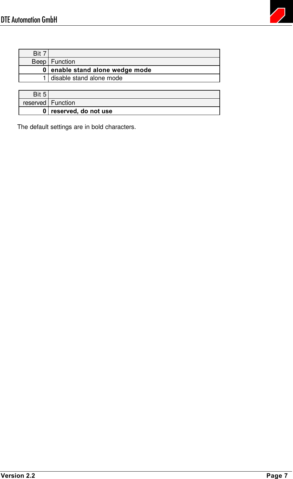
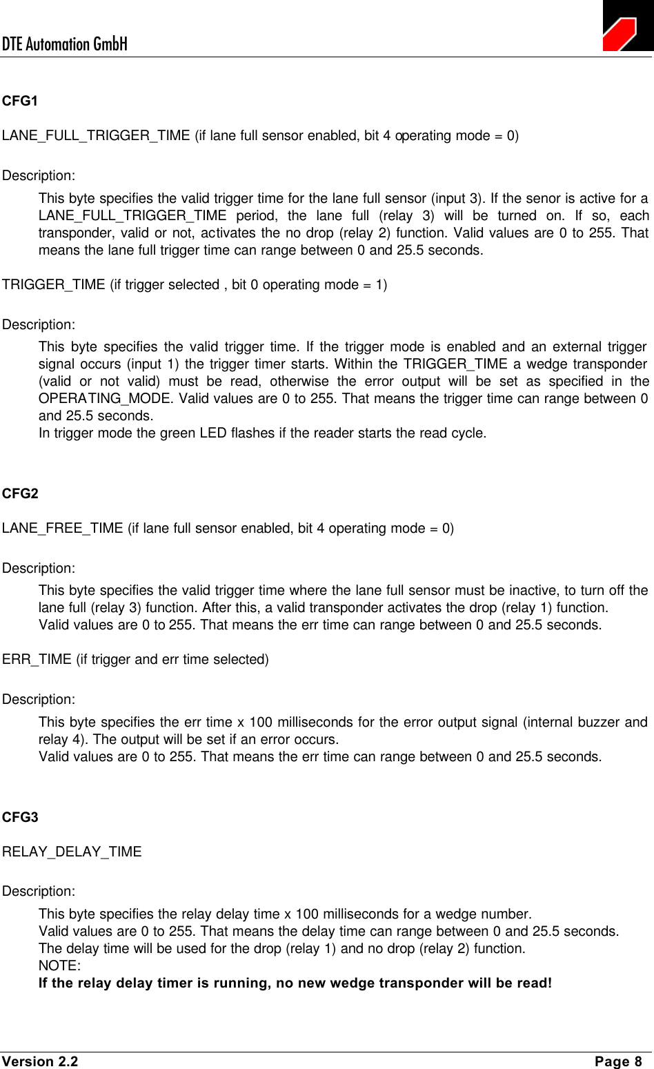
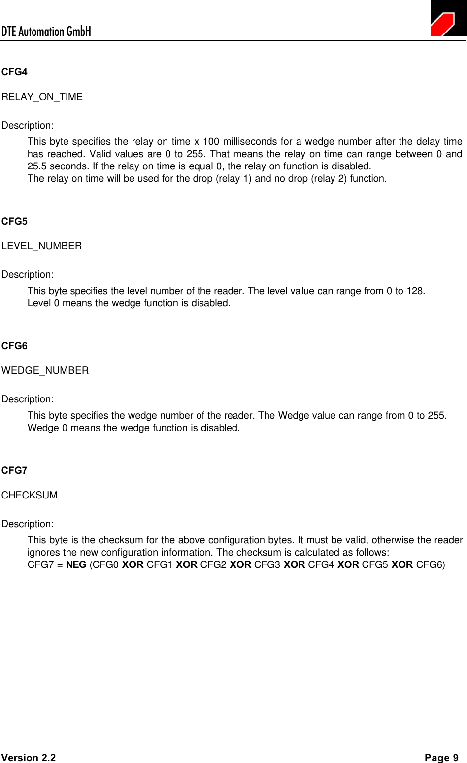
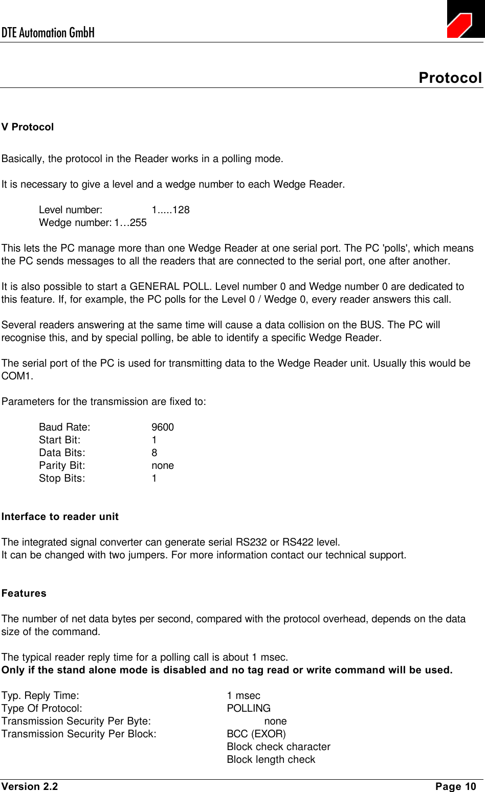
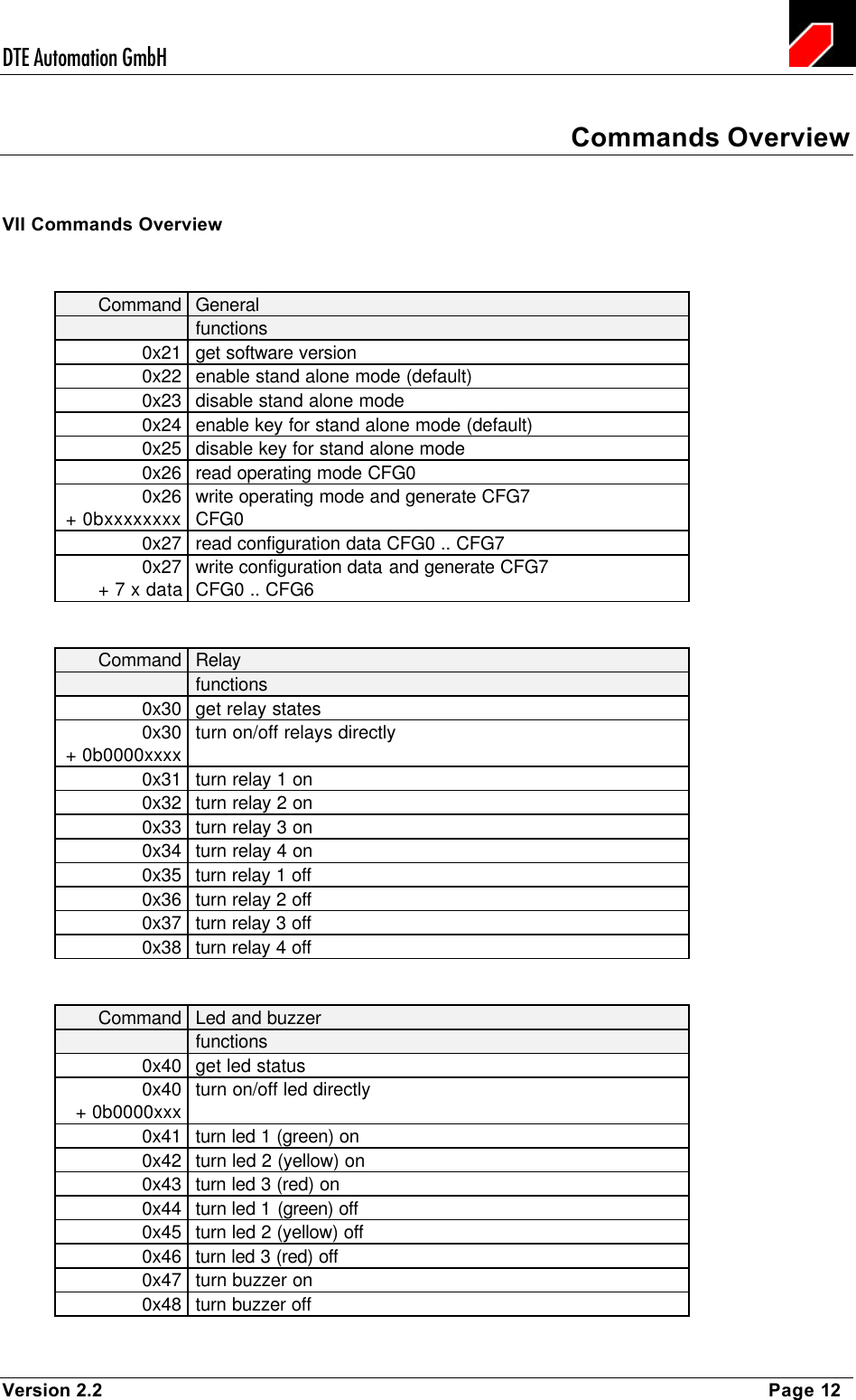
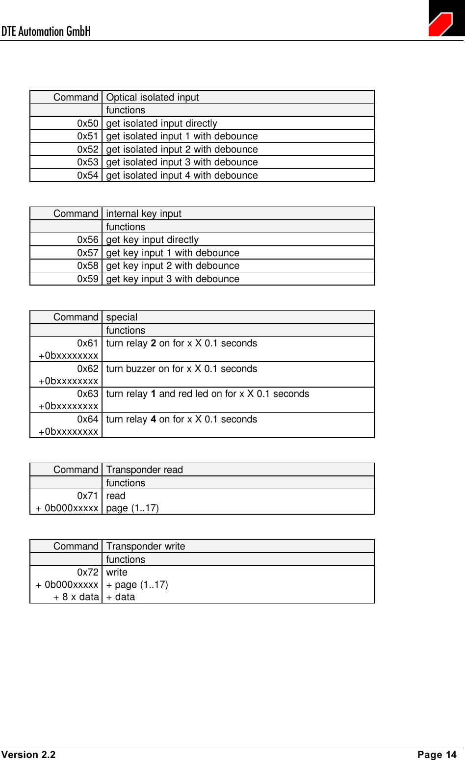
![DTE Automation GmbH Version 2.2 Page 11 Protocol Syntax VI Protocol Syntax The basic principle for communication is that the PC is always the MASTER, the Wedge Reader is always the SLAVE. Every action is initiated by the PC. This is required by the polling mode. There are COMMANDS from the PC to the reader and there are REPLIES from the reader to the PC. COMMANDS and REPLIES consist of HEADER, DATA and END part. The HEADER is always the same for all COMMANDS and REPLIES. The length of the transmitted DATA is coded in the HEADER. If, in the following description, some parameters are not named, the parameter will not be evaluated by the reader. HEADER STX, LEVEL-NUMBER, WEDGE-NUMBER, LENGTH, Type Meaning Length in bytes STX Start of Text, 02 Hex 1 LEVEL-NUMBER Level Number of the reader 1 WEDGE-NUMBER Wedge Number of the reader 1 LENGTH Length of DATA 1 DATA COMMAND,[data,] Type Meaning Length in bytes COMMAND Command 1 [data] Depends on type of command variable END BCC Type Meaning Length in bytes BCC Block check character XOR linking of the characters after STX to BCC-1 1](https://usermanual.wiki/DTE-Automation/IS-TR-241/User-Guide-290119-Page-11.png)