DTECH Labs 001 M3-EXT-PM1 Module User Manual
DTECH Labs Inc. M3-EXT-PM1 Module
UserManual.wiki
>
DTECH Labs
>
001 User Manual
User Manual
Navigation menu
Upload a User Manual
Namespaces
Wiki Guide
HTML
PDF
Info
Views
User Manual
Discussion / Help
Navigation
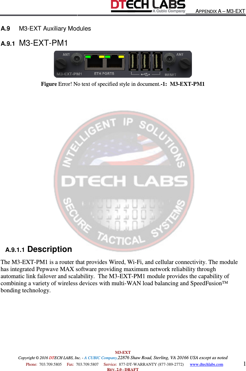
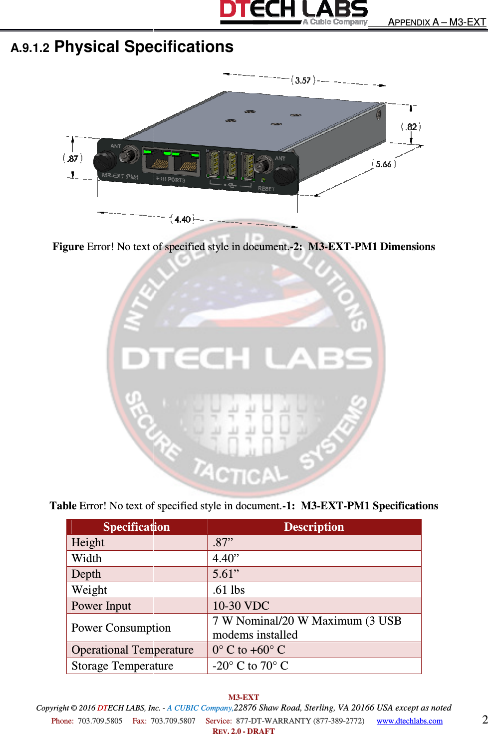
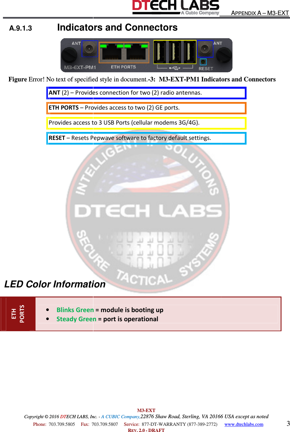
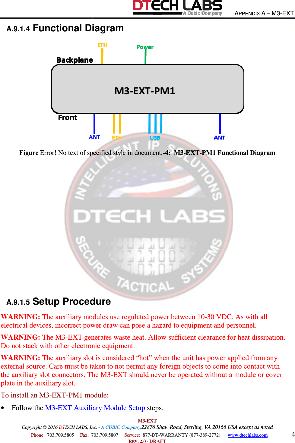
![All Materials Copyright © 2016 (877) DTM3-EXT USER’S GUIDE All Materials Copyright © 2016 DTECH LABS, Inc. - A CUBIC Company, Rev. 2.0 - DRAFT EAR Controlled 21580 Beaumeade Circle Suite 230 Ashburn, Virginia 20147 (703) 709-5805 voice (703) 709-5807 fax (877) DT-WARRANTY [877-389-2772] support@dtechlabs.com www.dtechlabs.com](https://usermanual.wiki/DTECH-Labs/001/User-Guide-2940654-Page-9.png)