DTECH Labs 001 M3-EXT-PM1 Module User Manual
DTECH Labs Inc. M3-EXT-PM1 Module
User Manual
Copyright © 2016 DT
ECH LABS, Inc.
Phone: 703.709.5805 Fax:
703.709.5807
A.9 M3-
EXT Auxiliary Modules
A.9.1 M3-EXT-PM1
Figure
Error! No text of specified style in document.
A.9.1.1 Description
The M3-EXT-
PM1 is a router that provides Wired, Wi
has integrated Pepwave MAX software providing maximum network reliability through
automatic link failover and scalability. The M3
combining a variety of wireless devices with multi
bonding technology.
M3-EXT
ECH LABS, Inc.
- A CUBIC Company,
22876 Shaw Road, Sterling, VA
20166 USA except as noted
703.709.5807
Service: 877-DT-WARRANTY (877-389-
2772)
R
EV
.
2.0
-
DRAFT
EXT Auxiliary Modules
Error! No text of specified style in document.
-1: M3-
EXT
PM1 is a router that provides Wired, Wi
-Fi, and cellular
connectivity. The module
has integrated Pepwave MAX software providing maximum network reliability through
automatic link failover and scalability. The M3
-EXT-
PM1 module provides the capability of
combining a variety of wireless devices with multi
-WAN loa
d balancing and SpeedFusion™
A
PPENDIX
A
–
M3-EXT
20166 USA except as noted
2772)
www.dtechlabs.com
1
EXT
-PM1
connectivity. The module
has integrated Pepwave MAX software providing maximum network reliability through
PM1 module provides the capability of
d balancing and SpeedFusion™
Copyright © 2016 DT
ECH LABS, Inc.
Phone: 703.709.5805 Fax:
703.709.5807
A.9.1.2
Physical Specifications
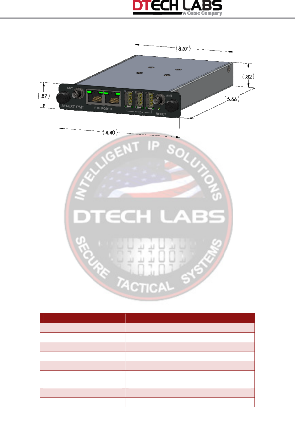
Figure
Error! No text of specified style in document.
Table
Error! No text of specified style in document.
Specification
Height
Width
Depth
Weight
Power Input
Power Consumption
Operational Temperature
Storage Temperature
M3-EXT
ECH LABS, Inc.
- A CUBIC Company,
22876 Shaw Road, Sterling, VA
20166 USA except as noted
703.709.5807
Service: 877-DT-WARRANTY (877-389-
2772)
R
EV
.
2.0
-
DRAFT
Physical Specifications
Error! No text of specified style in document.
-2: M3-EXT-
PM1 Dimensions
Error! No text of specified style in document.
-1: M3-EXT-
PM1 Specifications
Specification
Description
.87”
4.40”
5.61”
.61 lbs
10-30 VDC
Power Consumption
7 W Nominal/20 W Maximum (3 USB
modems installed
Operational Temperature
0° C to +60° C
Storage Temperature
-20° C to 70° C
A
PPENDIX
A
–
M3-EXT
20166 USA except as noted
2772)
www.dtechlabs.com
2
PM1 Dimensions
PM1 Specifications
7 W Nominal/20 W Maximum (3 USB
Copyright © 2016 DT
ECH LABS, Inc.
Phone: 703.709.5805 Fax:
703.709.5807
A.9.1.3
Indicators and Connectors
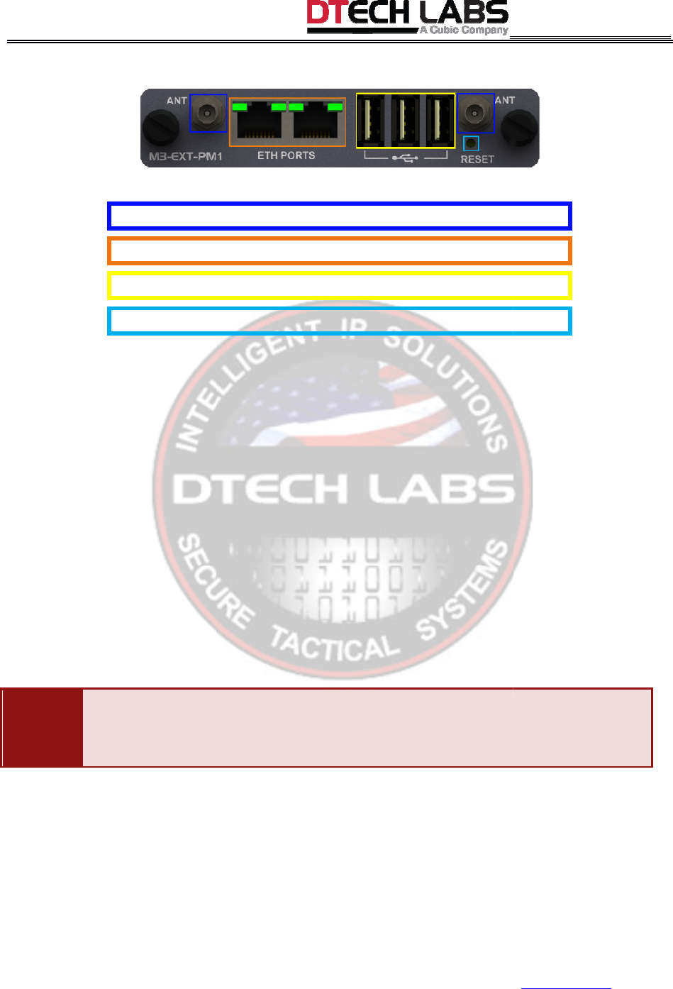
Figure
Error!
No text of specified style in document.
ANT
(2)
–
Provides connection for two (2) radio antennas.
ETH PORTS
–
Provides access to two (2) GE ports.
Provides access to 3 USB Ports (cellular modems 3G/4G).
RESET
–
Resets Pepwave software to factory default settings.
LED Color
Information
ETH
PORTS
•
Blinks Green
•
Steady Green
M3-EXT
ECH LABS, Inc.
- A CUBIC Company,
22876 Shaw Road, Sterling, VA
20166 USA except as noted
703.709.5807
Service: 877-DT-WARRANTY (877-389-
2772)
R
EV
.
2.0
-
DRAFT
Indicators and Connectors
No text of specified style in document.
-3: M3-EXT-
PM1 Indicators and Connectors
Provides connection for two (2) radio antennas.
Provides access to two (2) GE ports.
Provides access to 3 USB Ports (cellular modems 3G/4G).
Resets Pepwave software to factory default settings.
Information
Blinks Green
= module is booting up
Steady Green
= port is operational
A
PPENDIX
A
–
M3-EXT
20166 USA except as noted
2772)
www.dtechlabs.com
3
PM1 Indicators and Connectors
Copyright © 2016 DT
ECH LABS, Inc.
Phone: 703.709.5805 Fax:
703.709.5807
A.9.1.4
Functional Diagram
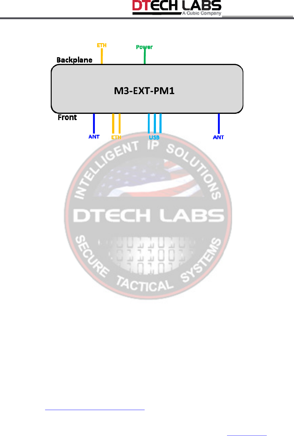
Figure
Error! No text of specified style in document.
A.9.1.5
Setup Procedure
WARNING:
The auxiliary modules use regulated power between 10
electrical devices, incorrect power draw can pose a hazard to equipment and personnel.
WARNING:
The M3-
EXT generates waste heat. Allow sufficient clearance for heat dissipation.
Do not stack with other electronic equipment.
WARNING:
The auxiliary slot is considered “hot” when the unit has power applied from any
external source. Care must be taken to
the auxiliary slot connectors. The M3
plate in the auxiliary slot.
To install an M3-EXT-
PM1 module:
•
Follow the M3-
EXT Auxiliary Module Setup
M3-EXT
ECH LABS, Inc.
- A CUBIC Company,
22876 Shaw Road, Sterling, VA
20166 USA except as noted
703.709.5807
Service: 877-DT-WARRANTY (877-389-
2772)
R
EV
.
2.0
-
DRAFT
Functional Diagram
Error! No text of specified style in document.
-4: M3-EXT-
PM1 Functional Diagram
Setup Procedure
The auxiliary modules use regulated power between 10
-
30 VDC. As with all
electrical devices, incorrect power draw can pose a hazard to equipment and personnel.
EXT generates waste heat. Allow sufficient clearance for heat dissipation.
Do not stack with other electronic equipment.
The auxiliary slot is considered “hot” when the unit has power applied from any
external source. Care must be taken to
not permit any foreign objects to come into contact with
the auxiliary slot connectors. The M3
-
EXT should never be operated without a module or cover
PM1 module:
EXT Auxiliary Module Setup
steps.
A
PPENDIX
A
–
M3-EXT
20166 USA except as noted
2772)
www.dtechlabs.com
4
PM1 Functional Diagram
30 VDC. As with all
electrical devices, incorrect power draw can pose a hazard to equipment and personnel.
EXT generates waste heat. Allow sufficient clearance for heat dissipation.
The auxiliary slot is considered “hot” when the unit has power applied from any
not permit any foreign objects to come into contact with
EXT should never be operated without a module or cover
Copyright © 2016 DT
ECH LABS, Inc.
Phone: 703.709.5805 Fax:
703.709.5807
A.9.1.6 M3-EXT-
PM1 Access
By default, all LAN interfaces have a DHCP server service running, therefore, your client devices
should get an IP address of 192.168.50.X/24 if your NIC is setup for DHCP.
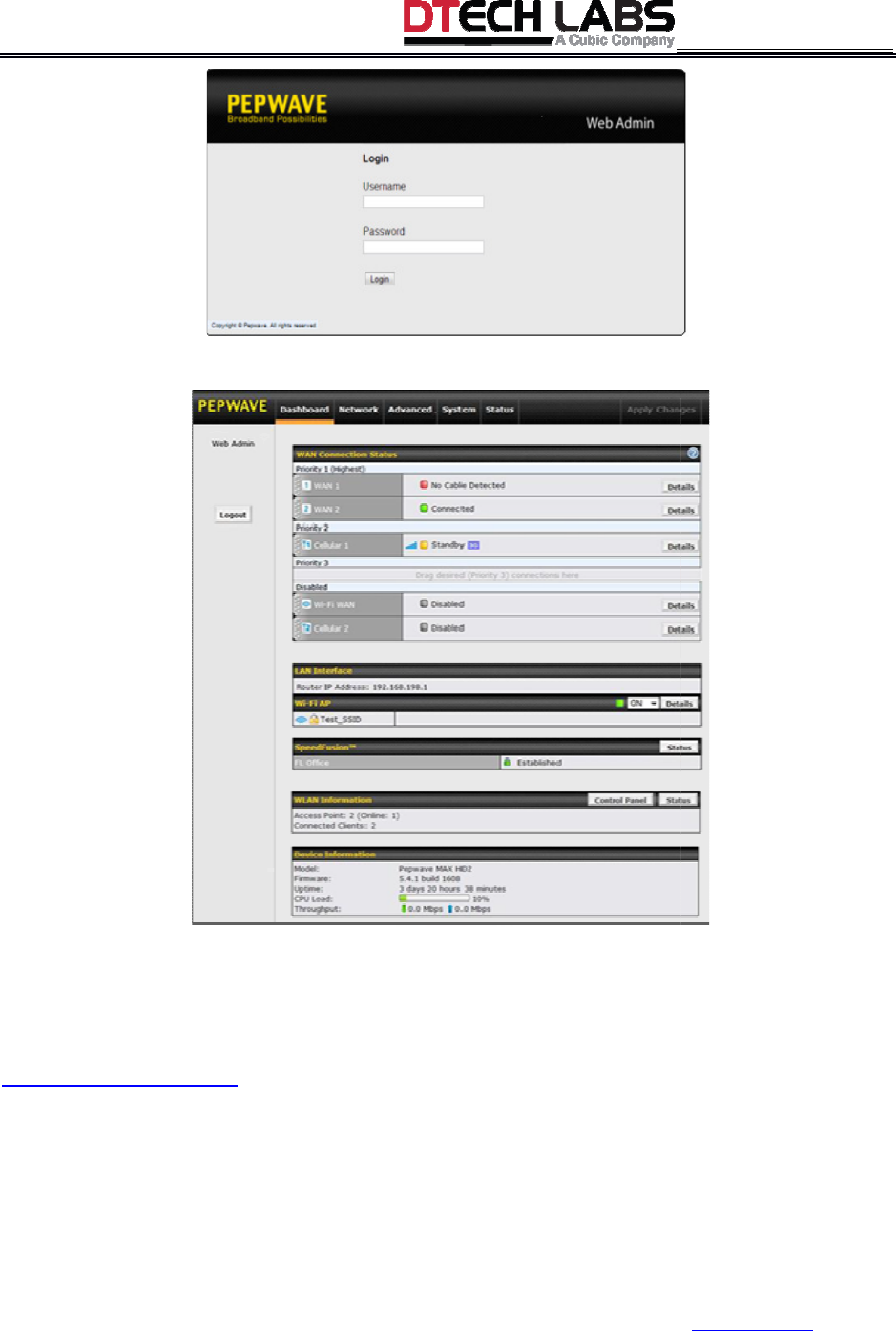
To connect to the
Web Admin interface;
1
Connect your PC to the right front panel ETH port and connect to one of the switch ports on the
M3-
EXT. Assumes that the M3
1.
Start a web browser.
2.
Ensure that your computer can ping 19
the
Manually Set IP Address
3.
Enter http://192.168.50.1
in the address field of the web browser.
Pepwave MAX LAN IP address.
4.
Enter the following to access the Web Admin Interface.
• Username
: admin
• Password
: admin
NOTE:
This is the default Username and Password of Pepwave MAX. The Admin and Read
User Password can be changed at
M3-EXT
ECH LABS, Inc.
- A CUBIC Company,
22876 Shaw Road, Sterling, VA
20166 USA except as noted
703.709.5807
Service: 877-DT-WARRANTY (877-389-
2772)
R
EV
.
2.0
-
DRAFT
PM1 Access
By default, all LAN interfaces have a DHCP server service running, therefore, your client devices
should get an IP address of 192.168.50.X/24 if your NIC is setup for DHCP.
Web Admin interface;
Connect your PC to the right front panel ETH port and connect to one of the switch ports on the
EXT. Assumes that the M3
-
EXT is properly configured to access the M3
Ensure that your computer can ping 19
2.168.50.1.
NOTE:
To change the IP address: follow
Manually Set IP Address
steps.
in the address field of the web browser.
NOTE:
Pepwave MAX LAN IP address.
Enter the following to access the Web Admin Interface.
This is the default Username and Password of Pepwave MAX. The Admin and Read
User Password can be changed at
System>Admin Security
of the Web Admin Interface.
A
PPENDIX
A
–
M3-EXT
20166 USA except as noted
2772)
www.dtechlabs.com
5
By default, all LAN interfaces have a DHCP server service running, therefore, your client devices
should get an IP address of 192.168.50.X/24 if your NIC is setup for DHCP.
Connect your PC to the right front panel ETH port and connect to one of the switch ports on the
EXT is properly configured to access the M3
-EXT-PM1.
To change the IP address: follow
NOTE:
This is the default
This is the default Username and Password of Pepwave MAX. The Admin and Read
-only
of the Web Admin Interface.
Copyright © 2016 DT
ECH LABS, Inc.
Phone: 703.709.5805 Fax:
703.709.5807
After successful login, the
Dashboard
NOTE: By default, the M3-
EXT
all outside (WAN) interfaces. All WAN interfaces are setup for DHCP client, by default.
5.
From the dashboard drag and drop your WAN priority preference.
NOTE:
For additional informa
http://www.pepwave.com
/
IMPORTANT:
By default, the left front panel ETH port is a defined as the WAN1 port within
Pepwave.
The right front panel ETH port is a LAN
the Pepwave GUI.
The backplane ETH p
ort is a LAN port.
M3-EXT
ECH LABS, Inc.
- A CUBIC Company,
22876 Shaw Road, Sterling, VA
20166 USA except as noted
703.709.5807
Service: 877-DT-WARRANTY (877-389-
2772)
R
EV
.
2.0
-
DRAFT
Dashboard
of Web Admin Interface displays.
EXT
-
PM1 is configured to NAT from all inside (LAN) interfaces to
all outside (WAN) interfaces. All WAN interfaces are setup for DHCP client, by default.
From the dashboard drag and drop your WAN priority preference.
For additional informa
tion, refer to the Pepwave MAX User Manual found at
By default, the left front panel ETH port is a defined as the WAN1 port within
The right front panel ETH port is a LAN
port but, can be user configured as the WAN2 port within
ort is a LAN port.
A
PPENDIX
A
–
M3-EXT
20166 USA except as noted
2772)
www.dtechlabs.com
6
PM1 is configured to NAT from all inside (LAN) interfaces to
all outside (WAN) interfaces. All WAN interfaces are setup for DHCP client, by default.
tion, refer to the Pepwave MAX User Manual found at
By default, the left front panel ETH port is a defined as the WAN1 port within
port but, can be user configured as the WAN2 port within

M3-EXT
U
SER
’
S
G
UIDE
All Materials Copyright © 2016 DTECH LABS, Inc. - A CUBIC Company,
Rev. 2.0 - DRAFT
EAR Controlled
Federal Communication Commission Interference Statement
This device complies with Part 15 of the FCC Rules. Operation is subject to the following two
conditions: (1) This device may not cause harmful interference, and (2) this device must
accept any interference received, including interference that may cause undesired operation.
NOTE: This equipment has been tested and found to comply with the limits for a Class A
digital device, pursuant to part 15 of the FCC Rules. These limits are designed to provide
reasonable protection against harmful interference when the equipment is operated in a
commercial environment. This equipment generates, uses, and can radiate radio frequency
energy and, if not installed and used in accordance with the instruction manual, may cause
harmful interference to radio communications. Operation of this equipment in a residential
area is likely to cause harmful interference in which case the user will be required to correct
the interference at his own expense.
FCC Caution: Any changes or modifications not expressly approved by the party responsible
for compliance could void the user's authority to operate this equipment.
This transmitter must not be co-located or operating in conjunction with any other antenna or
transmitter.
Radiation Exposure Statement:
This equipment complies with FCC radiation exposure limits set forth for an uncontrolled
environment.
1. 20cm minimum when the product is operated alone without co-transmitting with a plug-in
3G USB dongle device.
2. 40cm minimum when the product is operated with 1 plug-in 3G USB device which has
maximum of 7W ERP output power.
3. 50cm minimum when the product is operated with 2 plug-in 3G USB device which has
maximum of 7W ERP output power.
4. 60cm minimum when the product is operated with 3 plug-in 3G USB device which has
maximum of 7W ERP output power.
5. For co-transmission scenario which is not covered above, please consult the RF technician
or device supplier.

M3-EXT
U
SER
’
S
G
UIDE
All Materials Copyright © 2016 DTECH LABS, Inc. - A CUBIC Company,
Rev. 2.0 - DRAFT
EAR Controlled
This device is intended only for OEM integrators under the following conditions:
1. The transmitter module may not be co-located with any other transmitter or antenna.
2. Module approval valid only when the module is installed in the tested host or
compatible series of host which have similar RF exposure characteristic with equal or
larger antenna separation distance.
As long as 2 conditions above are met, further transmitter test will not be required. However,
the OEM integrator is still responsible for testing their end-product for any additional
compliance requirements required with this module installed.
End Product Labeling
The product can be kept as far as possible from the user body or set the device to lower
output power if such function is available. The final end product must be labeled in a visible
area with the following: “Contains FCC ID: 2AG56001”. The grantee's FCC ID can be used
only when all FCC compliance requirements are met.
Manual Information To the End User
The OEM integrator has to be aware not to provide information to the end user regarding how
to install or remove this RF module in the user’s manual of the end product which integrates
this module.
The end user manual shall include all required regulatory information/warning as show in this
manual.

All Materials Copyright © 2016
(877) DT
M3-EXT
U
SER
’
S
G
UIDE
All Materials Copyright © 2016
DTECH LABS, Inc. - A CUBIC Company,
Rev. 2.0 - DRAFT
EAR Controlled
21580 Beaumeade Circle
Suite 230
Ashburn, Virginia 20147
(703) 709-5805 voice
(703) 709-5807 fax
(877) DT
-WARRANTY [877-389-2772]
support@dtechlabs.com
www.dtechlabs.com