DUNKIRK Boiler Manual L0611511
User Manual: DUNKIRK DUNKIRK Boiler Manual DUNKIRK Boiler Owner's Manual, DUNKIRK Boiler installation guides
Open the PDF directly: View PDF ![]() .
.
Page Count: 67
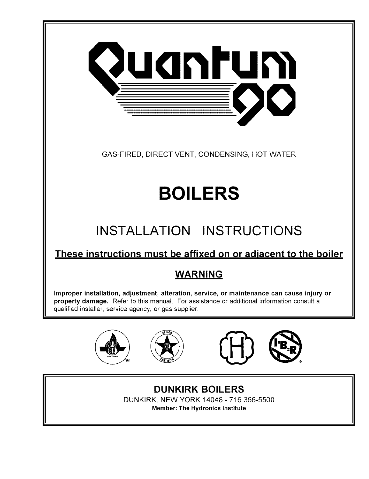
GAS-FIRED, DIRECT VENT, CONDENSING, HOT WATER
BOILERS
INSTALLATION INSTRUCTIONS
These instructions must be affixed on or adjacent to the boiler
WARNING
Improper installation, adjustment, alteration, service, or maintenance can cause injury or
property damage. Refer to this manual. For assistance or additional information consult a
qualified installer, service agency, or gas supplier.
@@
DUNKIRK BOILERS
DUNKIRK, NEW YORK 14048 - 716 366-5500
Member: The Hydronics Institute
TABLE OF CONTENTS INTRODUCTION ............................................................................. 3
BOILER RATINGS AND CAPACITIES .................................................................................. 4
RULES FOR SAFE INSTALLATION AND OPERATION ....................................................... 7
BEFORE INSTALLING THE BOILER .................................................................................... 7
A. codes ............................................................................................................................... 7
B. boiler sizing ...................................................................................................................... 8
C. considerations for boiler location ..................................................................................... 8
D. locating the boiler ............................................................................................................ 8
E. combustion air and vent pipe requirements ..................................................................... 9
F. condensate drain requirements ...................................................................................... 10
G. foundation requirements ................................................................................................ 11
H. removing existing boiler from common venting system ................................................. 11
PLACING THE BOILER ....................................................................................................... 11
NEAR BOILER PIPING ........................................................................................................ 12
A. supply and return lines ................................................................................................... 12
B. pressure relief valve ....................................................................................................... 16
C. expansion tank and make-up water ............................................................................... 16
D. condensate drain piping ................................................................................................ 19
E. filling condensate trap .................................................................................................... 19
F. chilled water piping ........................................................................................................ 20
COMBUSTION AIR AND VENT PIPE .................................................................................. 21
A. connections and terminations ........................................................................................ 21
B. installation ...................................................................................................................... 22
GAS SUPPLY PIPING .......................................................................................................... 25
A. check gas supply ........................................................................................................... 25
B. connecting the gas piping .............................................................................................. 25
C. checking the gas piping ................................................................................................. 26
ELECTRICAL WIRING ......................................................................................................... 27
A. electric power supply ..................................................................................................... 27
B. install your thermostat .................................................................................................... 28
C. field wiring connections ................................................................................................. 29
D. schematic wiring diagram .............................................................................................. 30
E. ladder wiring diagram ..................................................................................................... 31
CONTROLS AND ACCESSORIES ...................................................................................... 32
A. UT 1013-10 integrated boiler control ............................................................................ 32
B. gas control valve ............................................................................................................ 32
C. hot surface igniter .......................................................................................................... 32
D. L4006A high limit aquastat control ................................................................................ 32
E. draft inducer temperature safety switch ......................................................................... 32
F. casting temperature safety switch .................................................................................. 33
G. differential pressure air proving switch .......................................................................... 33
1
H. draft inducer ...................................................................................................................... 33
I. circulator pump .................................................................................................................. 33
J. drain valve ......................................................................................................................... 33
K. relief valve ........................................................................................................................ 34
L. flame rollout safety shutoff ................................................................................................ 34
M. external condensate pump ............................................................................................... 34
START-UP .............................................................................................................................. 34
A. water treatment and freeze protection .............................................................................. 34
B. filling boiler with water and purging air with diaphragm type expansion tanks .................. 35
C. filling boiler with water and purging air with conventional closed type expansion tanks .... 35
D. boiler in placing .................................................................................................................. 36
I. for your safety read before operating
II. operating instructions
III. to turn off gas to appliance
CHECK-OUT PROCEDURES AND ADJUSTMENTS ............................................................ 37
A. verify proper sequence of operation .................................................................................. 37
B. inspect venting and air intake system ................................................................................ 38
C. inspect condensate drain ................................................................................................... 38
D. inspect system piping ......................................................................................................... 38
E. test ignition system safety shutoff ...................................................................................... 38
F. test high limit control and adjust ......................................................................................... 38
G. test other safety controls .................................................................................................... 39
H. set thermostat heat ............................................................................................................ 39
1. measure the gas input rate ................................................................................................ 39
J. set thermostat to desired room temperature ...................................................................... 41
K. review all instructions ........................................................................................................ 41
L. installation and check-out certificate .................................................................................. 41
MAINTENANCE AND CLEANING .......................................................................................... 43
A. beginning of each season .................................................................................................. 43
B. daily during heating season ............................................................................................... 43
C. monthly during heating ...................................................................................................... 44
D. periodically during heating ................................................................................................. 44
E. end of each heating season -annual shut down procedure ............................................... 44
F. annual examination and cleaning of boiler components .................................................... 44
SERVICE HINTS ...................................................................................................................... 47
A flow chart/detailed sequence of operation ......................................................................... 47
B. trouble shooting ................................................................................................................. 50
C. differential air pressure switch check ................................................................................. 58
REPAIR PARTS ....................................................................................................................... 59
A. jacket and base .................................................................................................................. 59
B. condensate drain trap assembly ....................................................................................... 61
C. block and piping assembly ................................................................................................. 62
D. mixer and air pressure switch assembly ............................................................................ 64
E. flue adapter and exhauster assembly ................................................................................ 66
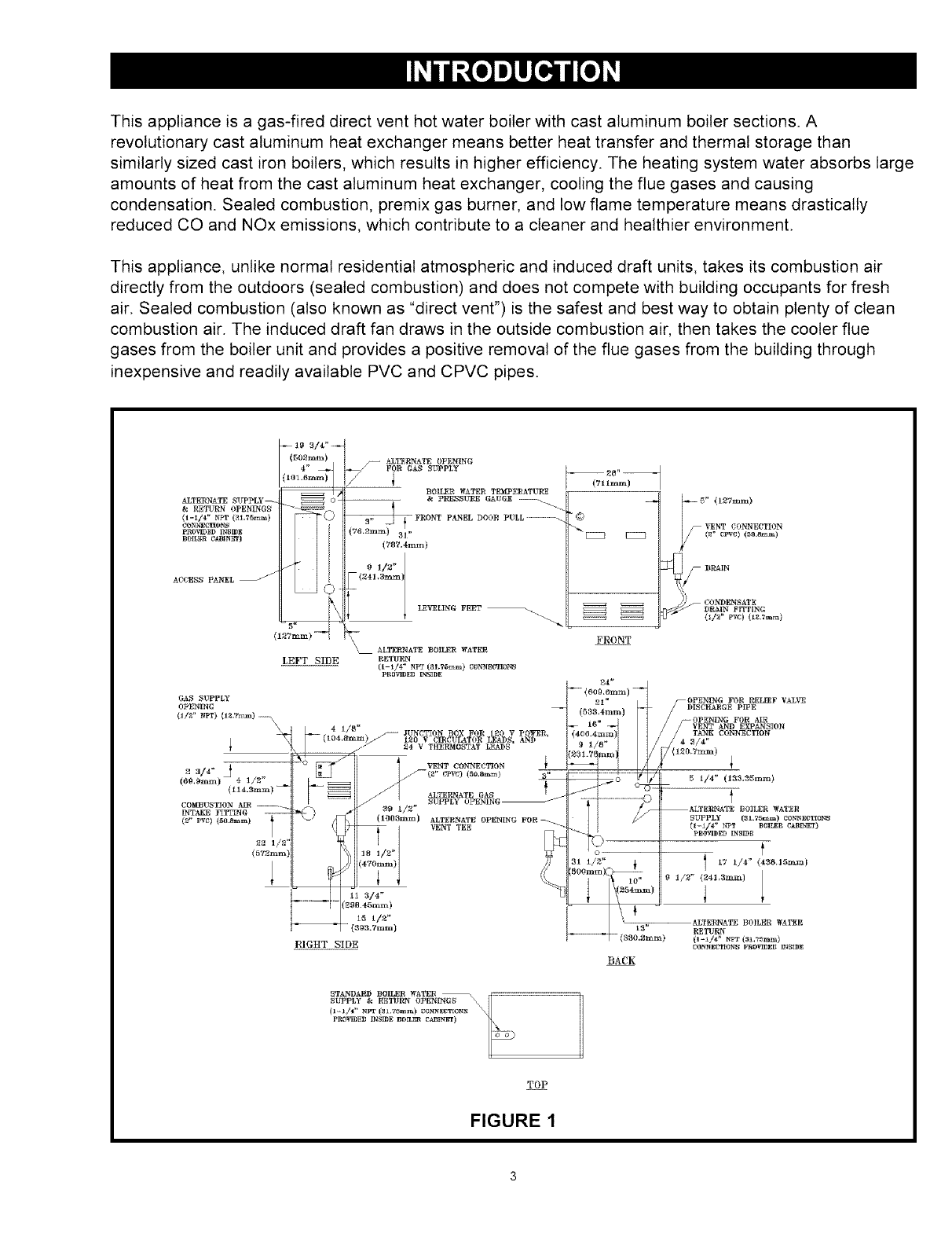
This appliance is a gas-fired direct vent hot water boiler with cast aluminum boiler sections. A
revolutionary cast aluminum heat exchanger means better heat transfer and thermal storage than
similarly sized cast iron boilers, which results in higher efficiency. The heating system water absorbs large
amounts of heat from the cast aluminum heat exchanger, cooling the flue gases and causing
condensation. Sealed combustion, premix gas burner, and low flame temperature means drastically
reduced CO and NOx emissions, which contribute to a cleaner and healthier environment.
This appliance, unlike normal residential atmospheric and induced draft units, takes its combustion air
directly from the outdoors (sealed combustion) and does not compete with building occupants for fresh
air. Sealed combustion (also known as "direct vent") is the safest and best way to obtain plenty of clean
combustion air. The induced draft fan draws in the outside combustion air, then takes the cooler flue
gases from the boiler unit and provides a positive removal of the flue gases from the building through
inexpensive and readily available PVC and CPVC pipes.
-- 19 3/_:-_
(5021nrn} /_ ALTEI_NATE OPENING
4" _ FOR GAS SUPPLY
.oSL V1
ALTERNATE SUPPLY _ 0 --- & PRESS1TI_E GAUCcE ------------
RETURN 0PENINGN _
(1-_./l" NPT (31.75_) t*RONT PANEL DOOR PULL ............... --
pROVIDBD IN_ION I I I (76,Stun:t) ....
I I I o i/s"
ACCESS PANfL _ I [ I •(Z4LSmm
(l_Tmm) -I I\
\__ ALTEERATE BOILER WATER
LEFT SIDE RETb_N
(f-l/4 _ NPT (fll.7_mm) _IONNE_IDNS
pR0_ED _tS]DE
TOP
FIGURE 1
-- 28" --
(711ram)
_©
FRONT
_5" (127ram)
VENT CONNECTION
/(g" cpvc) (_o.a=_)
i) J CONDENSATE
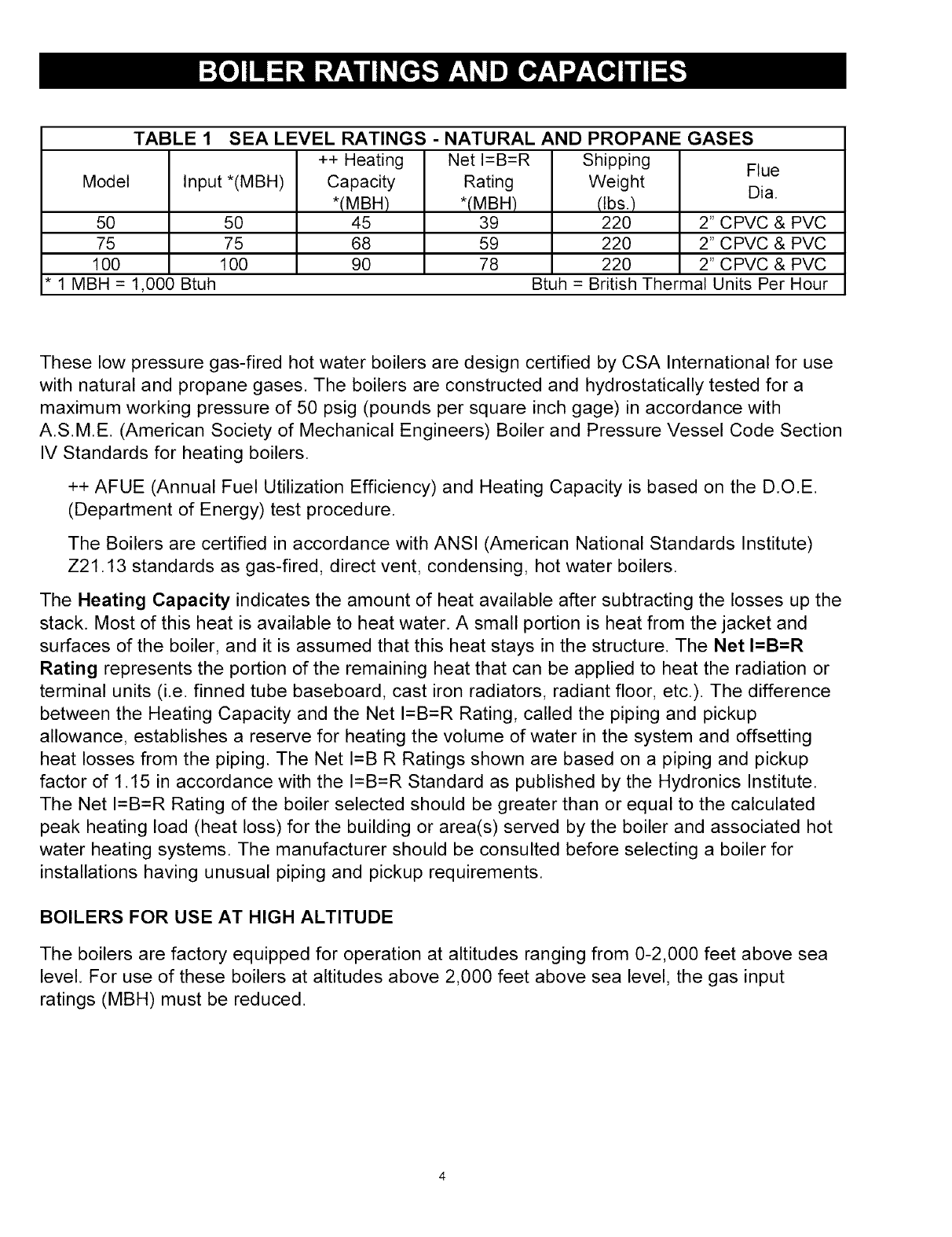
TABLE 1 SEA LEVEL RATINGS -NATURAL AND PROPANE GASES
Model
5O
75
100
Input *(MBH)
50
75
100
++ Heating
Capacity
*(MBH)
45
68
90
Net I=B=R
Rating
*(MBH)
39
59
78
Shipping
Weight
(tbs.)
220
220
220
Flue
Dia.
2" C PVC & PVC
2" C PVC & PVC
2" C PVC & PVC
* 1 MBH =1,000 Btuh Btuh =British Thermal Units Per Hour
These low pressure gas-fired hot water boilers are design certified by CSA International for use
with natural and propane gases. The boilers are constructed and hydrostatically tested for a
maximum working pressure of 50 psig (pounds per square inch gage) in accordance with
AS.ME (American Society of Mechanical Engineers) Boiler and Pressure Vessel Code Section
IV Standards for heating boilers.
++ AFUE (Annual Fuel Utilization Efficiency) and Heating Capacity is based on the D.O.E.
(Department of Energy) test procedure.
The Boilers are certified in accordance with ANSI (American National Standards Institute)
Z21.13 standards as gas-fired, direct vent, condensing, hot water boilers.
The Heating Capacity indicates the amount of heat available after subtracting the losses up the
stack. Most of this heat is available to heat water. A small portion is heat from the jacket and
surfaces of the boiler, and it is assumed that this heat stays in the structure. The Net I=B=R
Rating represents the portion of the remaining heat that can be applied to heat the radiation or
terminal units (i.e. finned tube baseboard, cast iron radiators, radiant floor, etc.). The difference
between the Heating Capacity and the Net I=B=R Rating, called the piping and pickup
allowance, establishes a reserve for heating the volume of water in the system and offsetting
heat losses from the piping. The Net I=B R Ratings shown are based on a piping and pickup
factor of 1.15 in accordance with the I=B=R Standard as published by the Hydronics Institute.
The Net I=B=R Rating of the boiler selected should be greater than or equal to the calculated
peak heating load (heat loss) for the building or area(s) served by the boiler and associated hot
water heating systems. The manufacturer should be consulted before selecting a boiler for
installations having unusual piping and pickup requirements.
BOILERS FOR USE AT HIGH ALTITUDE
The boilers are factory equipped for operation at altitudes ranging from 0-2,000 feet above sea
level. For use of these boilers at altitudes above 2,000 feet above sea level, the gas input
ratings (MBH) must be reduced.
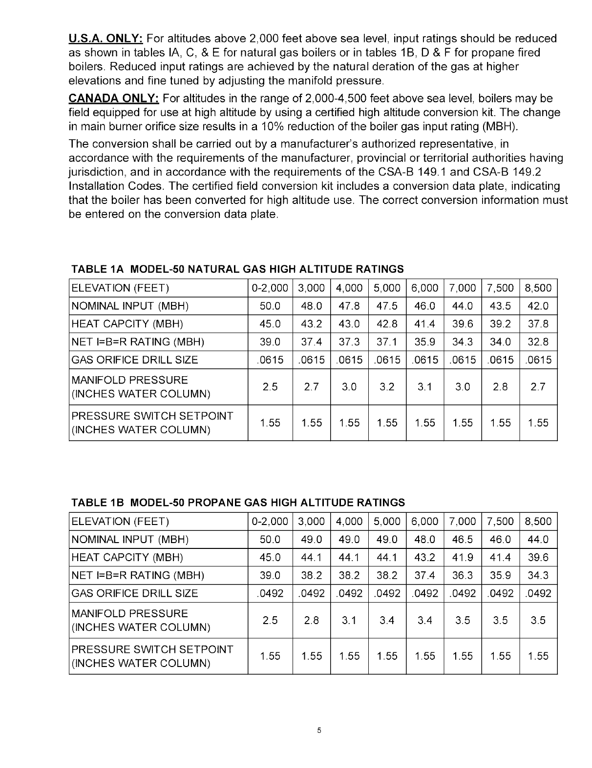
U.S.A. ONLY: For altitudes above 2,000 feet above sea level, input ratings should be reduced
as shown in tables IA, C, & E for natural gas boilers or in tables 1B, D & F for propane fired
boilers. Reduced input ratings are achieved by the natural deration of the gas at higher
elevations and fine tuned by adjusting the manifold pressure.
CANADA ONLY: For altitudes in the range of 2,000-4,500 feet above sea level, boilers may be
field equipped for use at high altitude by using a certified high altitude conversion kit. The change
in main burner orifice size results in a 10% reduction of the boiler gas input rating (MBH).
The conversion shall be carried out by a manufacturer's authorized representative, in
accordance with the requirements of the manufacturer, provincial or territorial authorities having
jurisdiction, and in accordance with the requirements of the CSA-B 149.1 and CSA-B 149.2
Installation Codes. The certified field conversion kit includes a conversion data plate, indicating
that the boiler has been converted for high altitude use. The correct conversion information must
be entered on the conversion data plate.
TABLE 1A MODEL-50 NATURAL GAS HIGH ALTITUDE RATINGS
ELEVATION (FEET) 0-2,000 3,000 4,000 5,000 6,000 7,000 7,500 8,500
NOMINAL INPUT (MBH) 50.0 48.0 47.8 47.5 46.0 44.0 43.5 42.0
HEAT CAPCITY (MBH) 450 43.2 43.0 42.8 41.4 39.6 39.2 37.8
NET I=B=R RATING (MBH) 39.0 37.4 37.3 37.1 35.9 34.3 34.0 32.8
GAS ORIFICE DRILL SIZE .0615 .0615 .0615 .0615 .0615 .0615 .0615 .0615
MANIFOLD PRESSURE 2.5 2.7 3.0 3.2 3.1 3.0 2.8 2.7
(INCHES WATER COLUMN)
PRESSURE SWITCH SETPOINT 1.55 1.55 1.55 1.55 1.55 1.55 1.55 1.55
(INCHES WATER COLUMN)
TABLE 1B MODEL-50 PROPANE GAS HIGH ALTITUDE RATINGS
ELEVATION (FEET) 0-2,000 3,000 4,000 5,000 6,000 7,000 7,500 8,500
NOMINAL INPUT (MBH) 50.0 49.0 49.0 49.0 48.0 46.5 46.0 44.0
HEAT CAPCITY (MBH) 450 44.1 44.1 44.1 43.2 41.9 41.4 39.6
NET I=B=R RATING (MBH) 39.0 38.2 38.2 38.2 37.4 36.3 35.9 34.3
GAS ORIFICE DRILL SIZE .0492 .0492 .0492 .0492 .0492 .0492 .0492 .0492
MANIFOLD PRESSURE 2.5 2.8 3.1 3.4 3.4 3.5 3.5 3.5
(INCHES WATER COLUMN)
PRESSURE SWITCH SETPOINT 1.55 1.55 1.55 1.55 1.55 1.55 1.55 1.55
(INCHES WATER COLUMN)
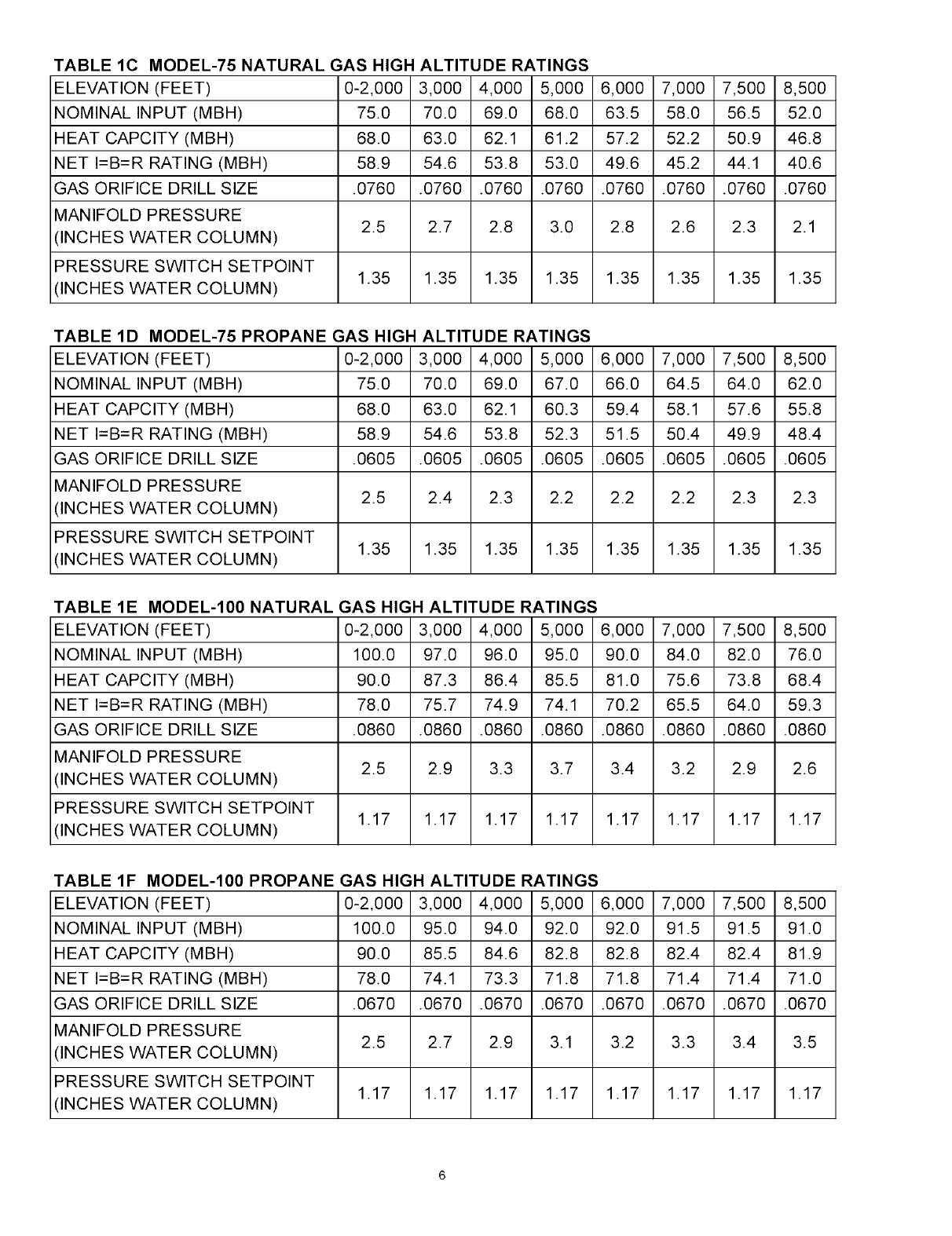
TABLE lC MODEL-75 NATURAL GAS HIGH ALTITUDE RATINGS
ELEVATION (FEET) 0-2,000 3,000 4,000 5,000 6,000 7,000 7,500 8,500
NOMINAL INPUT (MBH) 75.0 70.0 69.0 68.0 63.5 58.0 56.5 52.0
HEAT CAPClTY (MBH) 68.0 63.0 62.1 61.2 57.2 52.2 50.9 46.8
NET I=B=R RATING (MBH) 58.9 54.6 53.8 53.0 49.6 45.2 44.1 40.6
GAS ORIFICE DRILL SIZE .0760 .0760 .0760 .0760 .0760 .0760 .0760 .0760
MANIFOLD PRESSURE 2.5 2.7 2.8 3.0 2.8 2.6 2.3 2.1
(INCHES WATER COLUMN)
PRESSURE SWITCH SETPOINT 1.35 1.35 1.35 1.35 1.35 1.35 1.35 1.35
(INCHES WATER COLUMN)
TABLE 1D MODEL-75 PROPANE GAS HIGH ALTITUDE RATINGS
ELEVATION (FEET) 0-2,000 3,000 4,000 5,000 6,000 7,000 7,500 8,500
NOMINAL INPUT (MBH) 75.0 70.0 69.0 67.0 66.0 64.5 64.0 62.0
HEAT CAPClTY (MBH) 68.0 63.0 62.1 60.3 59.4 58.1 57.6 55.8
NET I=B=R RATING (MBH) 58.9 54.6 53.8 52.3 51.5 50.4 49.9 48.4
GAS ORIFICE DRILL SIZE .0605 .0605 .0605 .0605 .0605 .0605 .0605 .0605
MANIFOLD PRESSURE 2.5 2.4 2.3 2.2 2.2 2.2 2.3 2.3
(INCHES WATER COLUMN)
PRESSURE SWITCH SETPOINT 1.35 1.35 1.35 1.35 1.35 1.35 1.35 1.35
(INCHES WATER COLUMN)
TABLE 1E MODEL-100 NATURAL GAS HIGH ALTITUDE RATINGS
ELEVATION (FEET) 0-2,000 3,000 4,000 5,000 6,000 7,000 7,500 8,500
NOMINAL INPUT (MBH) 100.0 97.0 96.0 95.0 90.0 84.0 82.0 76.0
HEAT CAPClTY (MBH) 90.0 87.3 86.4 85.5 81.0 75.6 73.8 68.4
NET I=B=R RATING (MBH) 78.0 75.7 74.9 74.1 70.2 65.5 64.0 59.3
GAS ORIFICE DRILL SIZE .0860 .0860 .0860 .0860 .0860 .0860 .0860 .0860
MANIFOLD PRESSURE 2.5 2.9 3.3 3.7 3.4 3.2 2.9 2.6
(INCHES WATER COLUMN)
PRESSURE SWITCH SETPOINT 1.17 1.17 1.17 1.17 1.17 1.17 1.17 1.17
(INCHES WATER COLUMN)
TABLE 1F MODEL-100 PROPANE GAS HIGH ALTITUDE RATINGS
ELEVATION (FEET) 0-2,000 3,000 4,000 5,000 6,000 7,000 7,500 8,500
NOMINAL INPUT (MBH) 100.0 95.0 94.0 92.0 92.0 91.5 91.5 91.0
HEAT CAPClTY (MBH) 90.0 85.5 84.6 82.8 82.8 82.4 82.4 81.9
NET I=B=R RATING (MBH) 78.0 74.1 73.3 71.8 71.8 71.4 71.4 71.0
GAS ORIFICE DRILL SIZE .0670 .0670 .0670 .0670 .0670 .0670 .0670 .0670
MANIFOLD PRESSURE 2.5 2.7 2.9 3.1 3.2 3.3 3.4 3.5
(INCHES WATER COLUMN)
PRESSURE SWITCH SETPOINT 1.17 1.17 1.17 1.17 1.17 1.17 1.17 1.17
(INCHES WATER COLUMN)
I. Read the entire installation manual before beginning the installation. Failure to follow these
rules for safe installation and operation and these instructions could cause a malfunction of
the boiler and result in death, serious bodily injury, and/or property damage.
2. Check all applicable state and local building codes and utility company requirements
before installation. The installation must conform with these requirements in their
entirety. In the absence of these codes, use NFPA Installation Codes and good
industry practice.
3. Before servicing the boiler - allow the boiler to cool. Always shut off any electricity and
gas supply connected to the boiler prior to servicing.
4. Inspect gas line for leaks.
5. Be certain gas input rate is correct. Over firing may result in early failure of the boiler
sections. This may cause dangerous operation. Under firing may result in too much air
for the pre-mix burner causing poor or loss of combustion.
6. Never vent the products of combustion from this boiler to an enclosed space. Always
vent to the outdoors. Never vent to another room or to inside a building.
7. Be sure there is adequate outdoor air supply to boiler.for complete combustion.
8. Follow a regular service and maintenance schedule for efficient and safe operation. 9.
Keep boiler area clean of debris and free of combustible and flammable materials.
10. Proper through the wall or through the roof combustion venting shall be in accordance with the
materials and methods described in this manual. Installation must comply with local codes.
11. This boiler and related hot water heating systems are not do it yourself items. They
must be installed and serviced by qualified professionals.
WARNING
This boiler has been equipped for residential installations. If used for commercial applications, any
additional code requirements must be adhered to for installation. This may require additional
controls including but not limited to a low water cut off, a manual reset high temperature limit, and
wiring and/or piping modifications. The manufacturer is not responsible for any field installation
changes made to a boiler installation which are not described or acknowledged in this manual.
Complete all of the following prior to installing the boiler.
A= CODES
This boiler product is a gas-fired, direct vent, condensing boiler and must be installed in
accordance with all applicable federal, state and local building codes including, but not
limited to the following:
United States -Installation shall conform with National Fuel Gas Code (NFPA-54/ANSl
Z223. l-latest edition)
Canada - Installation shall be in accordance with CSA B 149.1 and .2. installation
codes.
Where required by the authority havingjurisdiction, the installation must conform to the
American Society of Mechanical Engineers Safety Code for Controls and Safety Devices
for Automatically Fired Boilers, No.CSD-1.
The installationmust conformto the requirementsof the authorityhavingjurisdictionor, inthe
absenceof such requirements,to the NationalFuelGas Code,ANSI Z223.1 - latest revision.
Installers - Follow local regulations with respect to installation of CO (Carbon
Monoxide) Detectors. Follow maintenance recommendations in this manual.
Techniciens -Veuillez vous conformer a la reglementation en vigueur concernant 1'
installations des detecteurs d'oxyde de carbone. Suivre les consignes
d'entretien figurant dans le manuel d'instruction ci-joint.
B. BOILER SIZING
Check to be sure you have selected the boiler with the proper capacity before starting
the installation. The I=B R Rating of the boiler selected should be greater than or equal
to the calculated peak heating load (heat loss) for the building or area(s) served by the
boiler and associated hot water heating systems. See the table "BOILER RATINGS
AND CAPACITIES".
• Heat loss calculations should be based on approved industry methods.
C. CONSIDERATIONS FOR BOILER LOCATION
Before selecting a location for the boiler, the following should be considered. Each boiler
considered.
• Supplied with the correct type of gas (natural gas or propane).
• Connected to a suitable combustion air intake piping system to supply the correct
amounts of fresh (outdoor) air for combustion. (maximum length 80' for the Model-100
boiler, and maximum length 100' for the Model-75 and Model-50 boilers).
• Connected to a suitable venting system to remove the hazardous products of gas
combustion (maximum length 80' for the Model-100 boiler, and maximum length 100' for
the Model-75 and Model-50 boilers).
• Connected to a suitable hot water heating system
• Supplied with a suitable electrical supply for all boiler motors and controls.
• Connected to a properly located thermostat or operating control. (not included with
boiler)
• Placed on level surface (must NOT be installed on carpeting)
• Condensate drain line must be pitched down to floor drain or external condensate
pump with reservoir at ¼" per foot (wood frame or blocks may be used to raise boiler).
D. LOCATING THE BOILER
TABLE 2 BOILER CLEARANCES
COMBUSTIBLE ACCESSIBILITY/
UNIT SERVICING
CONSTRUCTION CLEANING
TOP 1" 8" 8"
LEFT SIDE 1" 1" 1"
RIGHT SIDE 8"
BASE 1"
FRONT 0" 24" 24"
BACK 1"
INTAKE/VENT PI PI NG 0"
NEAR BOI LER HOT WATER 1"
WATER PIPING
1. Select a location which is level, central to the piping systems served and as close to the
vent and air intake terminals as possible.
2. Accessibility clearances, if more stringent (i.e. larger clearances) than required fire protection
clearances, must be used for the boiler installation. Accessibility clearances may be achieved
with the use of removable walls or partitions.
3. The boiler is approved for installation in closets and on combustible floors. This boiler
shall NOT be installed on carpeting.
4. The clearances shown in Table 2 indicate required clearances per IAS listing. A minimum
1" clearance must be maintained between combustible construction and each of the left,
top and back surfaces of the boiler. A minimum 8" clearance is required on the right side,
to allow room for the inlet air pipe. An 18" clearance must be maintained at a side where
passage is required to access another side for cleaning or servicing, inspection or
replacement of any parts that normally may require such attention. Allow at least 24" at
the front and left side and 8" at the top for servicing. No clearances are required to
venting or combustion air intake piping.
5. Equipment shall be installed in a location which facilitates the operation of venting and
combustion air intake piping systems as described in this manual.
6. Advise owner of boiler to keep venting and combustion air intake passages free of obstructions.
both the venting and combustion air intake piping systems connected to the outdoors must
permit flow through the piping systems without restrictions for the boiler to operate.
7. The boiler shall be installed such that the automatic gas ignition system components are
protected from water (dripping, spraying, rain, etc.) during operation and service
(circulator replacement, control replacement, etc.).
E. COMBUSTION AIR AND VENT PIPE REQUIREMENTS
This boiler requires a dedicated direct vent system. In a direct vent system, all air for
combustionis taken directly from outside atmosphere, and all flue products are discharged to
outside atmosphere.
Combustion air and vent pipe connections must terminate together in the same atmospheric
pressure zone, either through the roof or sidewall (roof termination preferred). See Fig.9 & 10
for required clearances.
CAUTION
KEEP BOILER AREA CLEAN OF DEBRIS AND FREE OF FLAMABLE AND COMBUSTIBLE
MATERIALS, VAPORS AND LIQUIDS
WARNING
When vent pipe is exposed to temperatures below freezing, such as when it passes through an
unheated space or when a chimney is used as a raceway, vent pipe must be insulated with 1/2"
Armafiex or equivalent. In extreme cold climate areas, use 3/4" Armafiex or equivalent.
Combustion air must be clean outdoor air. Combustion air must not be taken from inside struc-
ture because that air frequently is contaminated by halogens, which include fluorides, chlorides,
phosphates, bromides and iodides. These elements are found in aerosols, detergents, bleaches,
cleaning solvents, salts, air fresheners, paints, adhesives and other household products.
Locate combustion air inlet as far away as possible from swimming pool and swimming pool
pump house.
All combustion air and vent pipes must be airtight and watertight. Combustion air and vent
piping must also terminate exactly as shown in Fig.9 or 10.
Vent connections serving appliances vented by natural draft shall not be connected into any
portion of mechanical draft systems operating under positive pressure.
Solvent cements are combustible. Keep away from heat, sparks, and open flame. Use only in
well ventilated areas. Avoid breathing in vapor or allowing contact with skin or eyes.
FAILURE TO FOLLOW THE AFOREMENTIONED WARNINGS COULD RESULT IN FIRE,
PROPERTY DAMAGE, PERSONAL INJURY, OR DEATH.
F. CONDENSATE DRAIN REQUIREMENTS
Condensate drain line to be pitched down to floor drain at a minimum of I/4"per foot. An external
condensate pump (not furnished) may be used if floor drain is not available. The condensate
pump must be designed for flue gas condensate application
NOTE:I. Condensate trap is built into the boiler, an external trap is not required and should not
be used.
2. Wood frame or blocks may be used to raise the boiler to maintain drain pitch or to be
above external condensate pump reservoir.
3. There is a 115 volt AC receptacle provided on the service switch junction box which
is located at the boiler right side, to provide power for an external condensate
pump (if needed).
G. FOUNDATION REQUIREMENTS
Boiler must be placed on level surface. Boiler is NOT to be installed on carpeting.
10
NOTE: 1. If boiler is not level condensate drain lines will not function properly. Adjustable
feet are located on the boiler to make up for minor surface irregularities or tilt.
2. Wood frame or blocks may be used to raise boiler to maintain drain pitch or to be
above external condensate pump reservoir.
H. REMOVAL OF EXISTING BOILER FROM COMMON VENT SYSTEM
When an existing boiler is removed from a common venting system, the common venting
system is likely to be too large for proper venting of the appliances remaining connected to it.
At the time of removal of an existing boiler, the following steps shall be followed with each
appliance remaining connected to the common venting system placed in operation, while the
other appliances remaining connected to the common venting system are not in operation.
1. Seal any unused openings in the common venting system.
2. Visually inspect the venting system for proper size and horizontal pitch and determine
there is no blockage, or restrictions, leakage, corrosion and other deficiencies which could
cause an unsafe condition.
3. Insofar as is practical, close all. building doors and windows and all doors between the
space in which the appliances remaining connected to the common venting system are
located and other spaces of the building. Turn on clothes dryer and any appliance not
connected to the common venting system. Turn on any exhaust fans, such as range
hoods and bathroom exhaust, so they will operate at maximum speed. Do not operate a
summer exhaust fan. Close fire dampers.
4. Place in operation the appliance being inspected. Follow the lighting instructions. Adjust
thermostat so appliances will operate continuously.
5. Test for spillage at the draft hood relief opening after 5 minutes of main burner operation.
Use the flame of a match or candle, or the smoke from a cigarette, cigar or pipe.
6. After it has been determined that each appliance remaining connected to the common venting
system properly vents when tested as outlined above, return doors, windows, exhaust fans
and any other gas-burning appliance to their previous condition of use.
7. Any improper operation of the common venting system should be corrected so the
installation conforms with the National Fuel Code, NFPA-54/ANSI -Z223. l-latest revision,
or section 5 of CSA-B 149 for Canadian standards. When resizing any portion of the
common venting system, the common venting system should be resized to approach the
minimum size as determined using the appropriate tables in part 11 in the National Fuel
Gas Code, NFPA-54/ANSI- Z223.1-1atest revision, or section 5 of CSA-B 149 for
Canadian standards.
The boiler should be placed to provide the most direct connections to the combustion air, vent
and system piping as possible.
Place crated boiler as close to selected location as possible and uncrate boiler. The uncrated
boiler may be moved into position with an appliance dolly or 2-wheel hand truck. The dolly or hand
truck should be inserted under the left hand side of the boiler. It is possible to slide the boiler for a
short distance on a smooth floor or surface.
NOTE: Refer to manual section "LOCATING THE BOILER" for required clearances for servic
ing and maintenance.
CAUTION
Copper supply and return piping, must NOT be installed directly into aluminum boiler section
casings due to galvanic corrosion between dissimilar metals. Iron or steel bushings or pipe
nipples should be used between copper system piping and boiler to make final connection to
boiler. Also, the use of dielectric unions is acceptable. The packaged boiler is furnished with iron
piping in the front boiler section for the supply and return connections.
When the installation of the boiler is for a new heating system, first install all of the radiation
units (panels, radiators, baseboard, or tubing) and the supply and return mains. After all heating
system piping and components have been installed, make final connection of the system piping
to the boiler. A hot water boiler installed above radiation level must be equipped with a low water
cut off device. A periodic inspection is necessary us is flushing of float type devices, per low
water cut off manufacturers specific instructions.
A. SUPPLY AND RETURN LINES
The packaged boiler unit is set up to receive 1 1/4" NPT supply and return piping from top
access. The boiler unit can also be piped from the left side by turning the supply elbow, and
from the rear of the unit by removing plugs in the rear boiler section.
NOTE: The circulator pump and isolation valves are furnished within a carton inside the boiler
cabinet and can be installed at the installer preferred location.
12
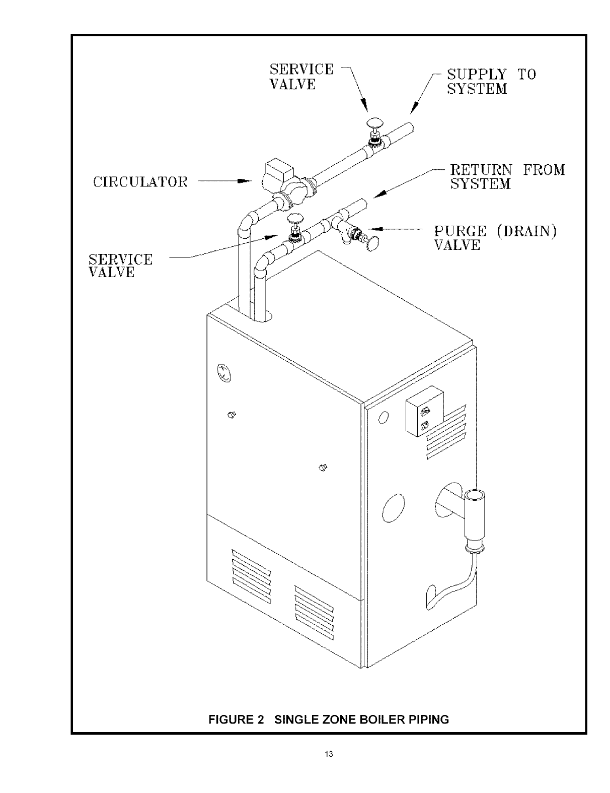
SERVICE \
VALVE '_
SUPPLY TO
SYSTEM
CIRCULATOR _/_ RETURN FROM
SYSTEM
SERVICE
VALVE
PURGE (DRAIN)
VALVE
FIGURE 2SINGLE ZONE BOILER PIPING
13
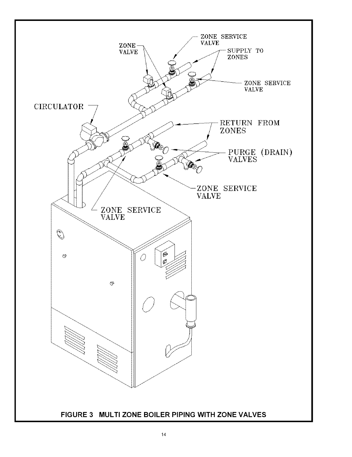
ZONE
VALVE
//-- VALvEZONESERVICE
/
SUPPLY
ZONES
TO
ZONE SERVICE
VALVE
CIRCULATOR
RETURN FROM
ZONES
PURGE (DRAIN)
VALVE S
//
_-/ZONE
VALVE
SERVICE
¢P
FIGURE 3 MULTI ZONE BOILER PIPING WITH ZONE VALVES
14
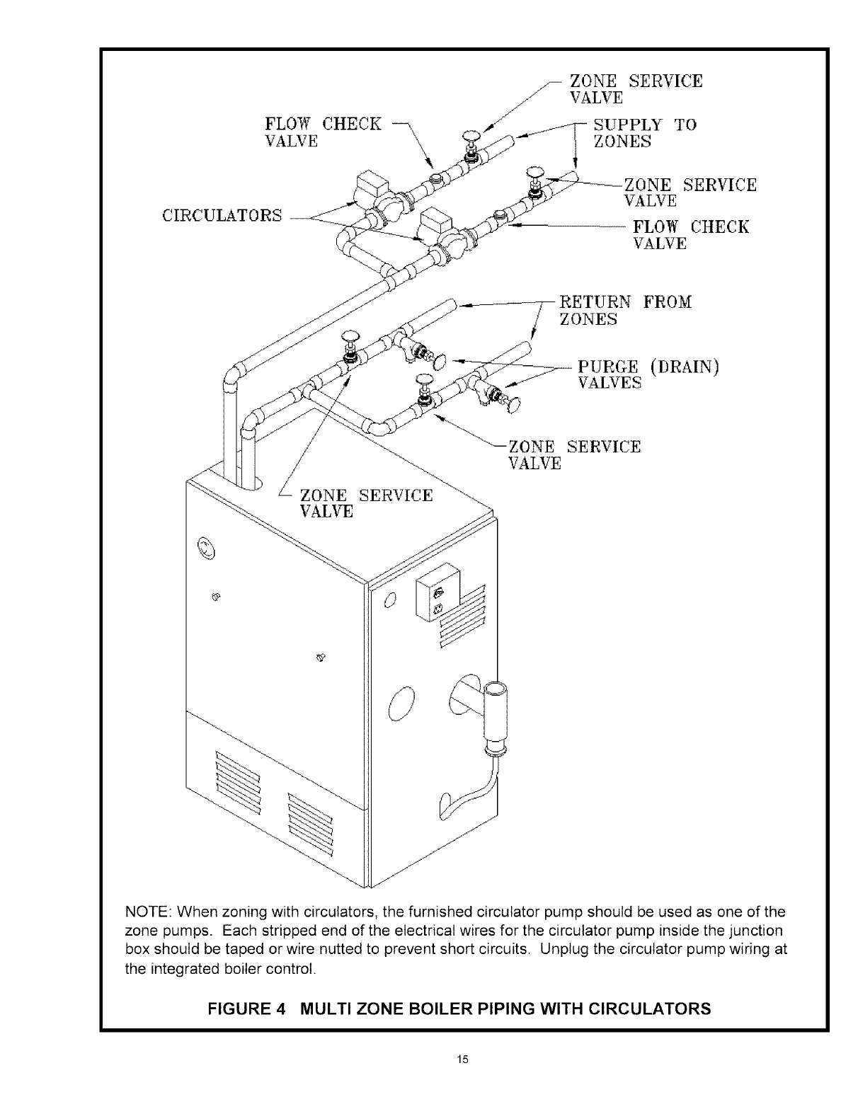
CIRCULATORS
ZONE SERVICE
////- VALVE
SUPPLY TO
-_7 ZONES
ZONE SERVICE
VALVE
FLOW CHECK
VALVE
FROM
ZONES
PURGE (DRAIN)
VALVES
ZONE
VALVE
SERVICE
_9
j"
j_
J
jJ
J
jJ
NOTE: When zoning with circulators, the furnished circulator pump should be used as one of the
zone pumps. Each stripped end of the electrical wires for the circulator pump inside the junction
box should be taped or wire nutted to prevent short circuits. Unplug the circulator pump wiring at
the integrated boiler control.
FIGURE 4 MULTI ZONE BOILER PIPING WITH CIRCULATORS
15
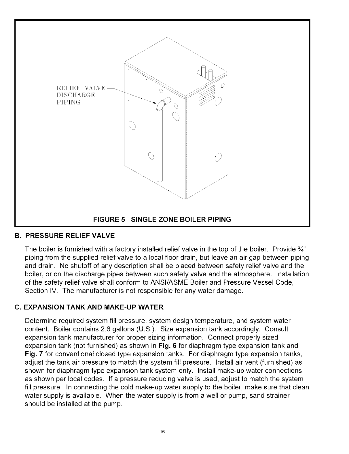
RELIEF VALVE _._
DISCHARGE
PIPING
'\. )
"\\
\\
FIGURE 5SINGLE ZONE BOILER PIPING
B. PRESSURE RELIEF VALVE
The boiler is furnished with a factory installed relief valve in the top of the boiler. Provide ¾"
piping from the supplied relief valve to a local floor drain, but leave an air gap between piping
and drain. No shutoff of any description shall be placed between safety relief valve and the
boiler, or on the discharge pipes between such safety valve and the atmosphere. Installation
of the safety relief valve shall conform to ANSl/ASME Boiler and Pressure Vessel Code,
Section IV. The manufacturer is not responsible for any water damage.
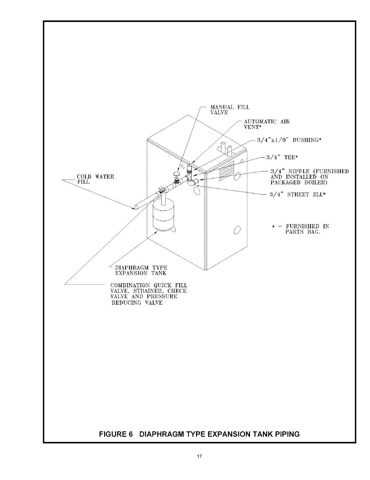
C. EXPANSION TANK AND MAKE-UP WATER
Determine required system fill pressure, system design temperature, and system water
content. Boiler contains 2.6 gallons (U.S.). Size expansion tank accordingly. Consult
expansion tank manufacturer for proper sizing information. Connect properly sized
expansion tank (not furnished) as shown in Fig. 6 for diaphragm type expansion tank and
Fig. 7 for conventional closed type expansion tanks. For diaphragm type expansion tanks,
adjust the tank air pressure to match the system fill pressure. Install air vent (furnished) as
shown for diaphragm type expansion tank system only. Install make-up water connections
as shown per local codes. If a pressure reducing valve is used, adjust to match the system
fill pressure. In connecting the cold make-up water supply to the boiler, make sure that clean
water supply is available. When the water supply is from a well or pump, sand strainer
should be installed at the pump.
16
COLD WATER
FILL
/
//
/
//
/
/
_JDIAPHRAGM TYPE
EXPANSION TANK
COMBINATION QUICK FILL
VALVE, STRAINER, CHECK
VALVE AND PRESSURE
REDUCING VALVE
_---- MANUAL FILL
VALVE
//- AUTOMATIC AIR
VENT*
//
3/4" TEE*
3//4 '' NIPPLE (FURNISHED
AND INSTALLED ON
PACKAGED BOILER)
3/4" STREET ELL*
* - FURNISHED IN
PARTS BAG.
FIGURE 6 DIAPHRAGM TYPE EXPANSION TANK PIPING
17
CLOSED TYPE
/_--_-'_ _'f EXPANSION TANK/_ "\\
/
j_
_EXPANSION TANK SERVICE
VALVE (GATE VALVE OR
FULL PORT BALL VALVE)
MANUAL FILL
VALVE
COLD WATER=_
FILL \
L_ CHECK AND PRESSURE
REDUCING VALVE
FIGURE 7 CONVENTIONAL (closed type) EXPANSION TANK PIPING
18
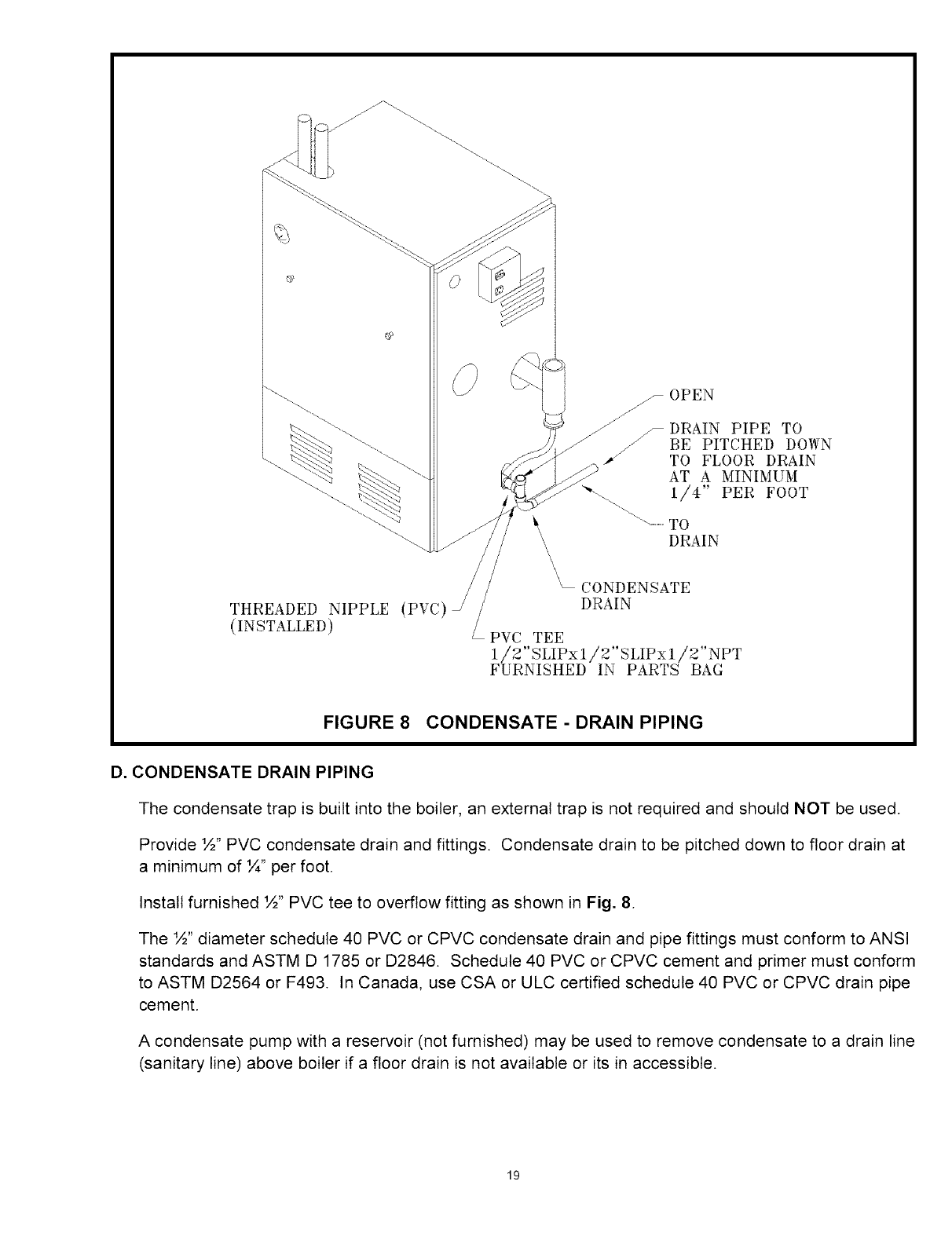
THREADED NIPPLE (PVC)
(INSTALLED)
_ OPEN
DRAIN PIPE TO
BE PITCHED DOWN
TO FLOOR DRAIN
AT A MINIMUM
"'- ..... 1/4" PER FOOT
TO
DRAIN
CONDENSATE
DRAIN
/PVC TEE
1/2"SLIPxI /2"SLIPxl !2"NPT
FURNISHED IN PARTS BAG
FIGURE 8 CONDENSATE - DRAIN PIPING
D. CONDENSATE DRAIN PIPING
The condensate trap is built into the boiler, an external trap is not required and should NOT be used.
Provide ½" PVC condensate drain and fittings. Condensate drain to be pitched down to floor drain at
a minimum of ¼" per foot.
Install furnished ½" PVC tee to overflow fitting as shown in Fig. 8.
The ½" diameter schedule 40 PVC or CPVC condensate drain and pipe fittings must conform to ANSI
standards and ASTM D 1785 or D2846. Schedule 40 PVC or CPVC cement and primer must conform
to ASTM D2564 or F493. In Canada, use CSA or ULC certified schedule 40 PVC or CPVC drain pipe
cement.
A condensate pump with a reservoir (not furnished) may be used to remove condensate to a drain line
(sanitary line) above boiler if a floor drain is not available or its in accessible.
19
E. FILLING CONDENSATE TRAP WITH WATER ON THE INITIAL START UP THE CONDEN
SATE TRAP MUST BE MANUALLY FILLED WITH WATER
The following are the steps required to initially fill the condensate trap for start up, these steps
are only required at the initial start up or if maintenance requires draining of the condensate trap:
1. Disconnect the vent condensate drain line from the bottom of the vent tee on the boiler.
2. Pour about 1 cup of cold tap water into the vent drain line with a proper funnel.
3. Excess water should go through the overflow and out through the condensate drain line.
Verify proper operation of the drain line (or external condensate pump if used).
4. Reinstall the vent drain line.
F. CHILLED WATER PIPING
The boiler, when used in connection with a refrigeration system, must be installed so the
chiller medium is piped in parallel with the boiler with appropriate valves to prevent the chilled
medium from entering the boiler.
The boiler piping system of a hot water boiler connected to heating coils is located in air
handling units where they may be exposed to refrigerated air circulation must be equipped
with flow control valves or other automatic means to prevent gravity circulation of the boiler
water during cooling cycle.
A. CONNECTIONS AND TERMINATION
For boilers connected to gas vents or chimneys, vent installations shall be in accordance with
part 7, Venting of Equipment, of the National Fuel Gas Code, ANSI 2223. l-latest revision,
CAN/CGA-B 149.1 and B 149.2, and applicable provisions of the local building codes.
Provisions for combustion and ventilation air must be in accordance with section 5.3, Air For
Combustion and Ventilation, of the National Fuel Gas Code,ANSI 2223. l-latest revision,
CAN/CGA-B 149.1 and B 149.2, or applicable provisions of the local building code.
These boilers require a dedicated direct vent system. All air for combustion is taken directly
from outdoors through the combustion air intake pipe. All flue products are discharged to the
outdoors through the vent pipe.
.See Fig.9 & 10 for combustion air and vent pipe roof and sidewall termination. (Roof termi
nation is preferred) Combustion air and vent pipes must terminate together in same atmo
spheric pressure zone as shown. Construction through which vent and air intake pipes
may be installed is a maximum 24 inches, minimum I/4" thickness.
.Combustion air and vent pipe fittings must conform to American National Standards Insti
tute (ANSI) standards and American Society for Testing and Materials (ASTM) standards
D1784 (schedule-40 CPVC), D1785 (schedule-40 PVC), D2665 (PVC-DWV), D2241
(SDR-21 and SDR-26 PVC), D2661 (ABS-DWV), or F628 (schedule-40 ABS). Pipe cement
and primer must conform to ASTM standards D2564 (PVC) or D2235 (ABS).
20
.
In Canada construct all combustion air and vent pipes for this unit of CSA or ULC certified
schedule-40 CPVC, schedule-40 PVC, PVC-DVVV or ABS-DVVV pipe and pipe cement.
SDR pipe is NOT approved in Canada.
Combustion air and vent piping connections on boiler are sized for 2" pipe. Any pipe size
change (to 3") must be made outside of the boiler casing in a vertical run of pipe to allow
for proper drainage of vent condensate. Due to potential for flue gas temperatures over
155°F, the first five (5) feet of vent pipe must be CPVC, the remaining vent pipe can be
PVC. If any elbows are employed within the first 5 feet of vent, they must be CPVC too.
Two (2) - 30" pieces of 2" CPVC pipe are furnished with the boiler.
NOTE: The transition from 2" pipe to 3" pipe must be made in a vertical run.
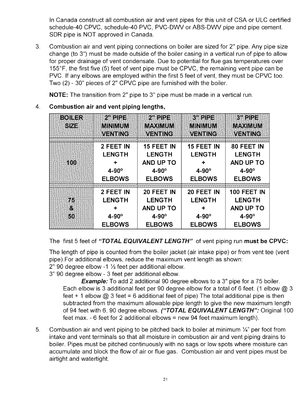
4. Combustion air and vent piping lengths,
2 FEET IN
LENGTH
+
4-90 °
ELBOWS
20 FEET IN
LENGTH
AND UP TO
4-90 °
ELBOWS
20 FEET IN
LENGTH
+
4-90 °
ELBOWS
100 FEET IN
LENGTH
AND UP TO
4-90 °
ELBOWS
.
The first 5 feet of "TOTAL EQUIVALENT LENGTH" of vent piping run must be CPVC:
The length of pipe is counted from the boiler jacket (air intake pipe) or from vent tee (vent
pipe).For additional elbows, reduce the maximum vent length as shown:
2" 90 degree elbow -1 ½ feet per additional elbow.
3" 90 degree elbow - 3 feet per additional elbow.
Example: To add 2 additional 90 degree elbows to a 3" pipe for a 75 boiler.
Each elbow is 3 additional feet per 90 degree elbow for a total of 6 feet. (1 elbow @ 3
feet + 1 elbow @ 3 feet = 6 additional feet of pipe) The total additional pipe is then
subtracted from the maximum allowable pipe length to give the new maximum length
of 94 feet with 6, 90 degree elbows. ("TOTAL EQUIVALENT LENGTH": Original 100
feet max. - 6 feet for 2 additional elbows = new 94 feet maximum length).
Combustion air and vent piping to be pitched back to boiler at minimum ¼" per foot from
intake and vent terminals so that all moisture in combustion air and vent piping drains to
boiler. Pipes must be pitched continuously with no sags or low spots where moisture can
accumulate and block the flow of air or flue gas. Combustion air and vent pipes must be
airtight and watertight.
21
.
.
Consideration for the following should be used when determining an appropriate location
for termination of combustion air and vent piping.
• Comply with all clearances required as stated in paragraph 7.
• Termination should be positioned where vent vapors will not damage plants/shrubs or air
conditioning equipment.
• Termination should be positioned so that it will not be effected by wind eddy, air born
leaves, snow, or recirculated flue gases.
• Termination should be positioned where it will not be subjected to potential damage by
foreign objects, such as stones, balls, etc..
• Termination should be positioned where vent vapors are not objectionable.
• Put vent on a wall away from the prevailing winter wind. Locate or guard the vent to
prevent accidental contact with people or pets.
• Terminate the vent above normal snowline. Avoid locations where snow may drift and
block the vent. Ice or snow may cause the boiler to shut down if the vent becomes
obstructed.
• Under certain conditions, flue gas will condense, forming moisture, and may be corrosive.
In such cases, steps should be taken to prevent building materials at the vent from being
damaged by exhaust of flue gas.
The venting system shall terminate at least 3 feet above any forced air inlet (except the
boiler's combustion air inlet) within 10 feet. The venting system shall terminate at least 12
inches from any air opening into any building. The bottom of the vent shall be located at
least 12 inches above grade. Termination of the vent shall be not less than 7 feet above an
adjacent public walkway. The vent terminal shall not be installed closer than 3 feet from the
inside corner of an L shaped structure. Termination of the vent should be kept at least 3
feet away from vegetation. The venting system shall terminate at least 4 feet horizontally
from, and in no case above or below, unless a 4 foot horizontal distance is maintained, from
electric meters, gas meters, regulators, and relief equipment.
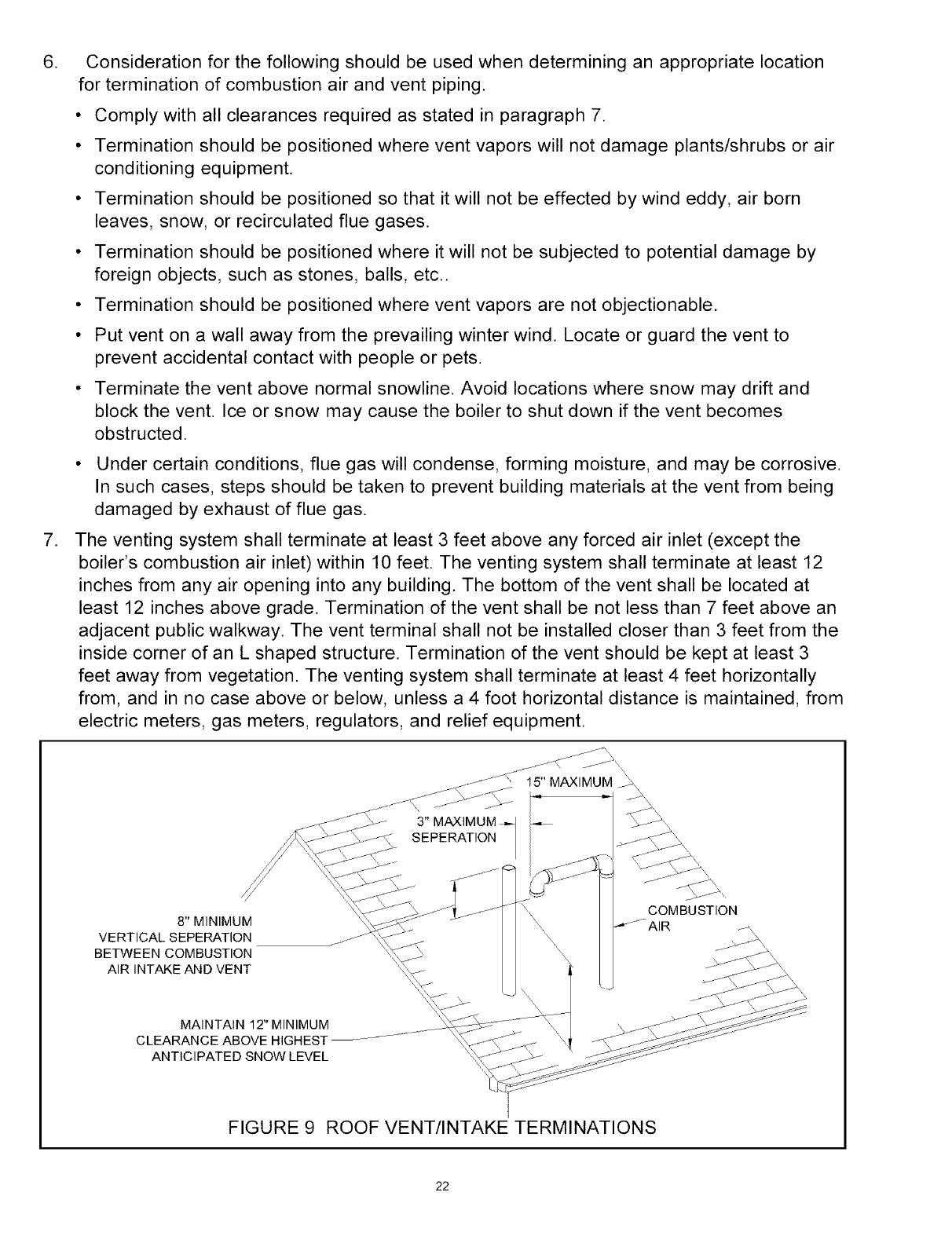
8" MINIMUM
VERTICAL SEPERATION
BETWEEN COMBUSTION
AIR INTAKE AND VENT
MAINTAIN 12" MINIMUM
CLEARANCE ABOVE HIGHEST
ANTICIPATED SNOW LEVEL
COMBUSTION
FIGURE 9 ROOF VENT/INTAKE TERMINATIONS
22
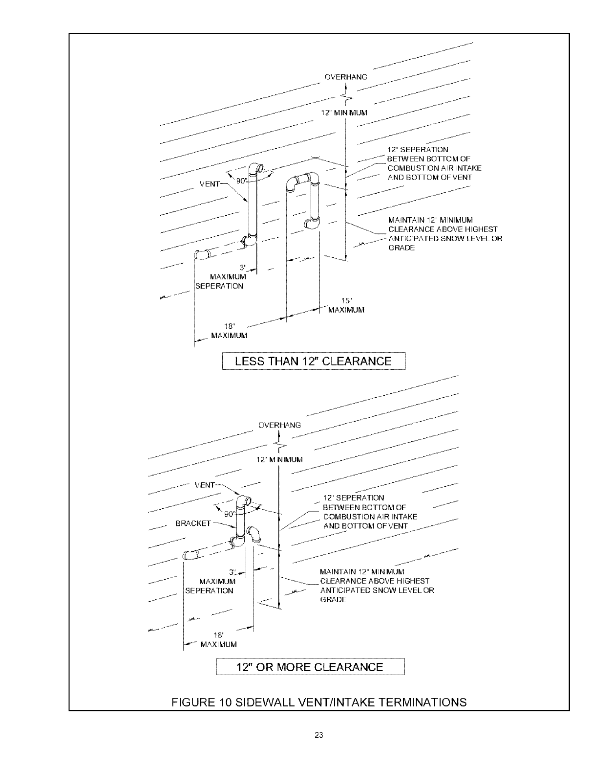
MAXIMUM
SEPERATION
18"
MAXIMUM
15"
.----," J_MAXIMUM
J
MAINTAIN 12" MINIMUM
CLEARANCE ABOVE HIGHEST
. _ ANTICIPATED SNOW LEVEL OR
J'_ GRADE
I LESS THAN 12" CLEARANCE I
12" MINIMUM
__" j_, 12" SEPERATION
_'90o_ J BETWEEN BOTTOM OF /
j- OOMBUST_ONAIRINTAKE_
// 0_AOKET--_I_ ANDBOTTOMO_VE__
/
_-_ MAXIMUIvl
SEPERATION
18"
_ MAXIMUM
J
f/J
MAINTAIN 12" MINIMUM
-'_ CLEARAN CE A BOVE H IGHEST
ANTICIPATED SNOW LEVEL OR
GRADE
I 12" OR MORE CLEARANCE I
FIGURE 10 SIDEWALL VENT/INTAKE TERMINATIONS
23
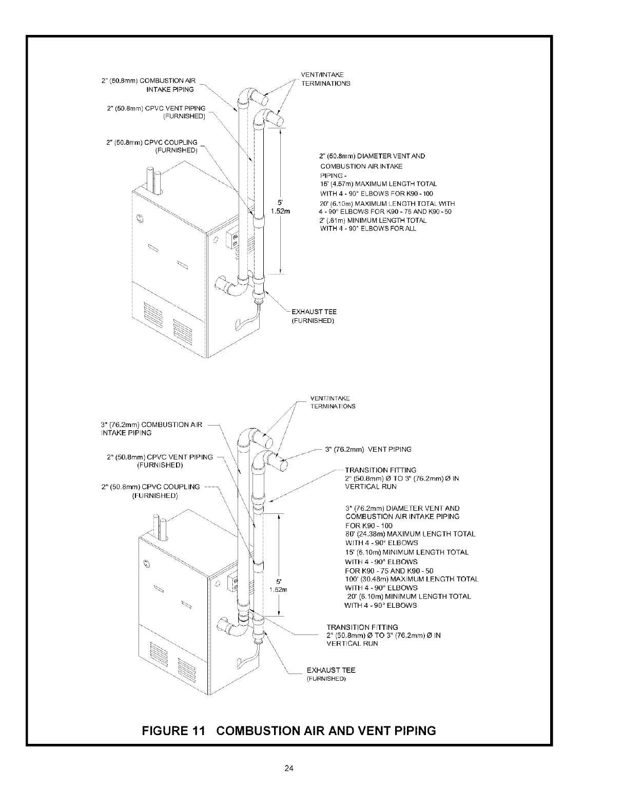
2" (50.8ram) COMBUSTION AIR
INTAKE PIPING "\_
2" (50.8mm) CPVC VENT PIPING
(FURNISHED) --x
\
x
2" (50.8ram) CPVC COUPLING
(FURNISHED) \\
/_/s/\\\\\\
VENT/INTAKE
S _/]7 TERMINATIONS
/
/
/
5'
1.52m
2" (50.8mm) DIAMETER VENTAND
COMBUSTION AIR INTAKE
PIPING -
15' (4.57m) MAXIMUM LENGTH TOTAL
WITH 4 - 900 ELBOWS FOR Kg0-100
20' (6.10m) MAXIMUM LENGTH TOTAL WITH
4 - 90 ° ELBOWS FOR K90 - 75 AND K90 - 50
2' (.61m) MINIMUM LENGTH TOTAL
WITH 4 - 90 ° ELBOWS FORALL
\4 EXHAUST TEE
(FURNISHED)
3" (76.2mm) COMBUSTION AIR _\
INTAKE PIPING _.
\\,
2" (50.8mm) CPVC VENT PIPING _
(FURNISHED)
2" (50.8mm) CPVC COUPLING \
(FURNISHED)
VENT/INTAKE
/_ TERMINATIONS
/?
,/ /
/ /
/
/
/
/_-- 3" (76.2mm) VENT PIPING
_ TRANSITION FITTING
_ 2" (5O.8mm) O TO 3" (76.2mm) O IN
_ VERTICAL RUN
3" (7B.2mm) DIAMETER VENT AND
COMBUSTION AIR INTAKE PIPING
FOR K90 - 100
80' (24,38m) MAXIMUM LENGTH TOTAL
WITH 4 - 90 ° ELBOWS
15' (6.10m) MINIMUM LENGTH TOTAL
WITH 4 -90 ° ELBOWS
FOR K90 - 75 AND K90 - 50
5' lOB' (30.48m) MAXIMUM LENGTH TOTAL
1.52m WITH 4 -90 ° ELBOWS
20' (6.10m) MINIMUM LENGTH TOTAL
WITH 4 - 90 _ ELBOWS
TRANSITION FITTING
2" (50.8ram) !21TO 3" (76.2mm) O IN
VERTICAL RUN
/i
/-
\_ EXHAUST TEE
(FURN SHED)
FIGURE 11 COMBUSTION AIR AND VENT PIPING
24
B. INSTALLATION
1. Attach combustion air intake piping to supplied Fernco 2" coupling on mixer. Attach
vent piping to furnished 2" CPVC vent tee on draft inducer outlet.
NOTE: All pipe joints are to be water tight.
2. Working from the boiler to the outside, cut pipe to required length(s).
3. Deburr inside and outside of pipe.
4. Chamfer outside edge of pipe for better distribution of primer and cement.
5. Clean and dry all surfaces to be joined.
6. Check dry fit of pipe and mark insertion depth on pipe.
NOTE: It is recommended that all pipes be cut, prepared, and pre-assembled before
permanently cementing any joint.
7. After pipes have been cut and pre-assembled, apply cement primer to pipe fitting
socket and end of pipe to insertion mark. Quickly apply approved cement to end of pipe
and fitting socket (over primer). Apply cement in light, uniform coat on the inside of
socket to prevent buildup of excess cement. Apply second coat.
8. While cement is still wet, insert pipe into socket with a'/a turn twist. Be sure pipe is fully
inserted into fitting socket.
9. Wipe excess cement from joint. A continuous bead of cement will be visible around
perimeter of a properly made joint.
10. Handle pipe joint carefully until cement sets.
11. Support combustion air and vent piping a minimum of every 5 feet using pre-formed
metal hanging straps. Do not rigidly support pipes. Allow movement due to expansion
and contraction.
12. Slope combustion air and vent pipes toward boiler a minimum of I/4" per linear foot with
no sags between hangers.
13. Use appropriate methods to seal openings where vent and combustion air pipes pass
through roof or side wall.
A. CHECK GAS SUPPLY
The gas pipe to your boiler must be the correct size for the length of run and for the total
BTU per hour input of all gas utilization equipment connected to it. See Table 3 for the
proper size. Be sure your gas line complies with local codes and gas company
requirements.
The boiler and its individual shutoff valve must be disconnected from the gas supply piping
system during any pressure testing of that system at test pressures in excess of '/z psig (3.5kpa).
The boiler must be isolated from the gas supply piping system by closing its individual
manual shutoff valve during any pressure testing of the gas supply piping system at test
pressures equal to or less than '/z psig (3.50ka).
MAXIMUM GAS SUPPLY PRESSURE
MINIMUM GAS SUPPLY PRESSURE
NATURAL GAS
10" w.c.
7" w.c.
PROPANE GAS
14" w.c.
10" w.c.
25
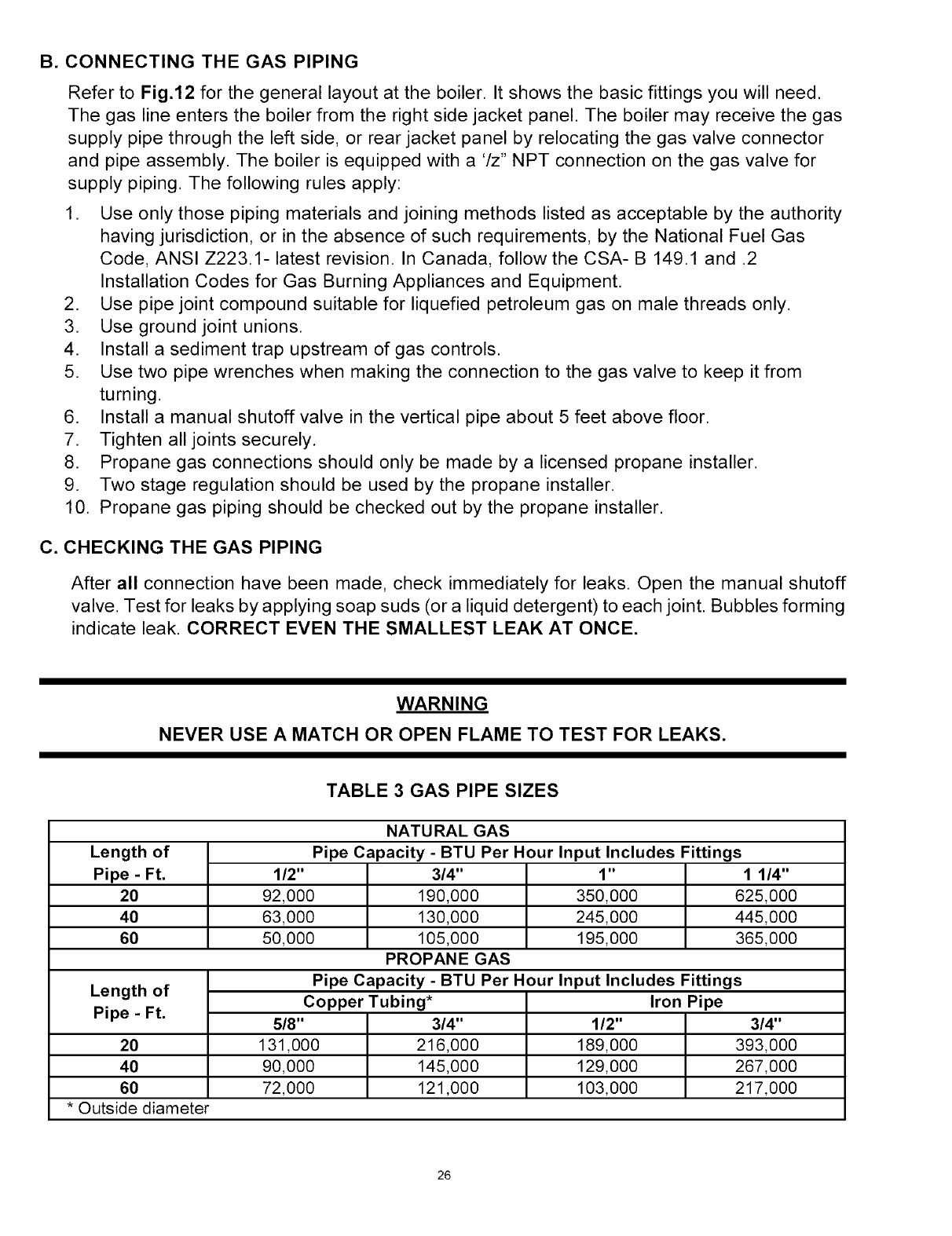
B. CONNECTING THE GAS PIPING
Refer to Fig.12 for the general layout at the boiler. It shows the basic fittings you will need.
The gas line enters the boiler from the right side jacket panel. The boiler may receive the gas
supply pipe through the left side, or rear jacket panel by relocating the gas valve connector
and pipe assembly. The boiler is equipped with a '/z" NPT connection on the gas valve for
supply piping. The following rules apply:
1. Use only those piping materials and joining methods listed as acceptable by the authority
having jurisdiction, or in the absence of such requirements, by the National Fuel Gas
Code, ANSI Z223.1- latest revision. In Canada, follow the CSA- B 149.1 and .2
Installation Codes for Gas Burning Appliances and Equipment.
2. Use pipe joint compound suitable for liquefied petroleum gas on male threads only.
3. Use ground joint unions.
4. Install a sediment trap upstream of gas controls.
5. Use two pipe wrenches when making the connection to the gas valve to keep it from
turning.
6. Install a manual shutoff valve in the vertical pipe about 5 feet above floor.
7. Tighten all joints securely.
8. Propane gas connections should only be made by a licensed propane installer.
9. Two stage regulation should be used by the propane installer.
10. Propane gas piping should be checked out by the propane installer.
C. CHECKING THE GAS PIPING
After all connection have been made, check immediately for leaks. Open the manual shutoff
valve. Test for leaks by applying soap suds (or a liquid detergent) to each joint. Bubbles forming
indicate leak. CORRECT EVEN THE SMALLEST LEAK AT ONCE.
WARNING
NEVER USE A MATCH OR OPEN FLAME TO TEST FOR LEAKS.
TABLE 3 GAS PIPE SIZES
NATURAL GAS
Length of Pipe Capacity- BTU Per Hourlnputlncludes FiRings
Pipe - Ft. 1/2" 3/4" 1" 1 1/4"
20 92,000 190,000 350,000 625,000
40 63,000 130,000 245,000 445,000
60 50,000 105,000 195,000 365,000
PROPANE GAS
Length of Pipe Capacity- BTU Per Hourlnputlncludes Fittings
Copper Tubing* Iron Pipe
Pipe - Ft. 5/8" 3/4" 1/2" 3/4"
20 131,000 216,000 189,000 393,000
40 90,000 145,000 129,000 267,000
60 72,000 121,000 103,000 217,000
*Outside diameter
26

The length of pipe or tubing should be measured from the gas meter or propane second stage regulator.
GAS SUPPLY
" ,/ PIP ING
//z SHIrT-OFF
VALVE
J SEDIMENT
TRAP
GROUND JOINT
UNION
/-
FIGURE 12 GAS PIPING
WARNING
TURN OFF ELECTRICAL POWER AT FUSE BOX BEFORE MAKING ANY LINE
VOLTAGE CONNECTIONS. FOLLOW LOCAL ELECTRICAL CODES.
All electrical work must conform to local codes as well as the National Electrical Code, ANSI/
NFPA70, latest revision. In Canada, electrical wiring shall comply with the Canadian Electrical
Codes, CSAC22.1 and .2
A. ELECTRIC POWER SUPPLY
Prior to making any line voltage connections, service switch at boiler should be in the off
position and the power turned off at the fuse box
Run a separate 120 volt circuit from a sperate over current protection device in the
electrical service entrance panel. This should be a 15 ampere circuit. A service switch has
been pre-wired and located on the exterior boiler jacket. See Fig. 13 for diagram showing
location of service switch junction box and power supply connection points. Connect black
(hot) lead from the power supply
27
to either of the unused brass screws on the service switch. Connect the white (neutral) lead from
the power supply to the white screw on the service switch. Connect the green (ground) lead
from the power supply to the ground (green) screw on the service switch. The receptacle on the
service switch is always powered regardless of whether the switch is on or off, and could be
used as a power supply for an external condensate pump if one is used.
The boiler, when installed, must be electrically grounded in accordance with the requirements of
the authority having jurisdiction or, in the absence of such requirements, with the National Elec-
trical Code, ANSI/NFPA-70, latest revision. In Canada, electrical wiring shall comply with the
Canadian Electrical Codes, CSA-C22.1 and .2.
Run a 14 gauge or heavier copper wire from the boiler to a grounded connection in the service
panel or a properly driven and electrically grounded ground rod.
B. INSTALL YOUR THERMOSTAT
The thermostat location has an important effect on the operation of your boiler system. BE
SURE TO FOLLOW THE INSTRUCTIONS INCLUDED WITH YOUR THERMOSTAT.
Locate the thermostat about five feet above the floor on an inside wall. It may be mounted di-
rectly on the wall or on a vertical mounted outlet box. It should be sensing average room tem-
perature. Avoid the Following:
DEAD SPOTS: COLD SPOTS: HOTSPOTS:
Behind doors
Comers and alcoves
Concealed pipes or ducts
Stairwells - drafts
Unheated rooms on
other side of wall
Concealed pipes Lamps
Fireplace Direct sunlight
TV sets Kitchens
Radios
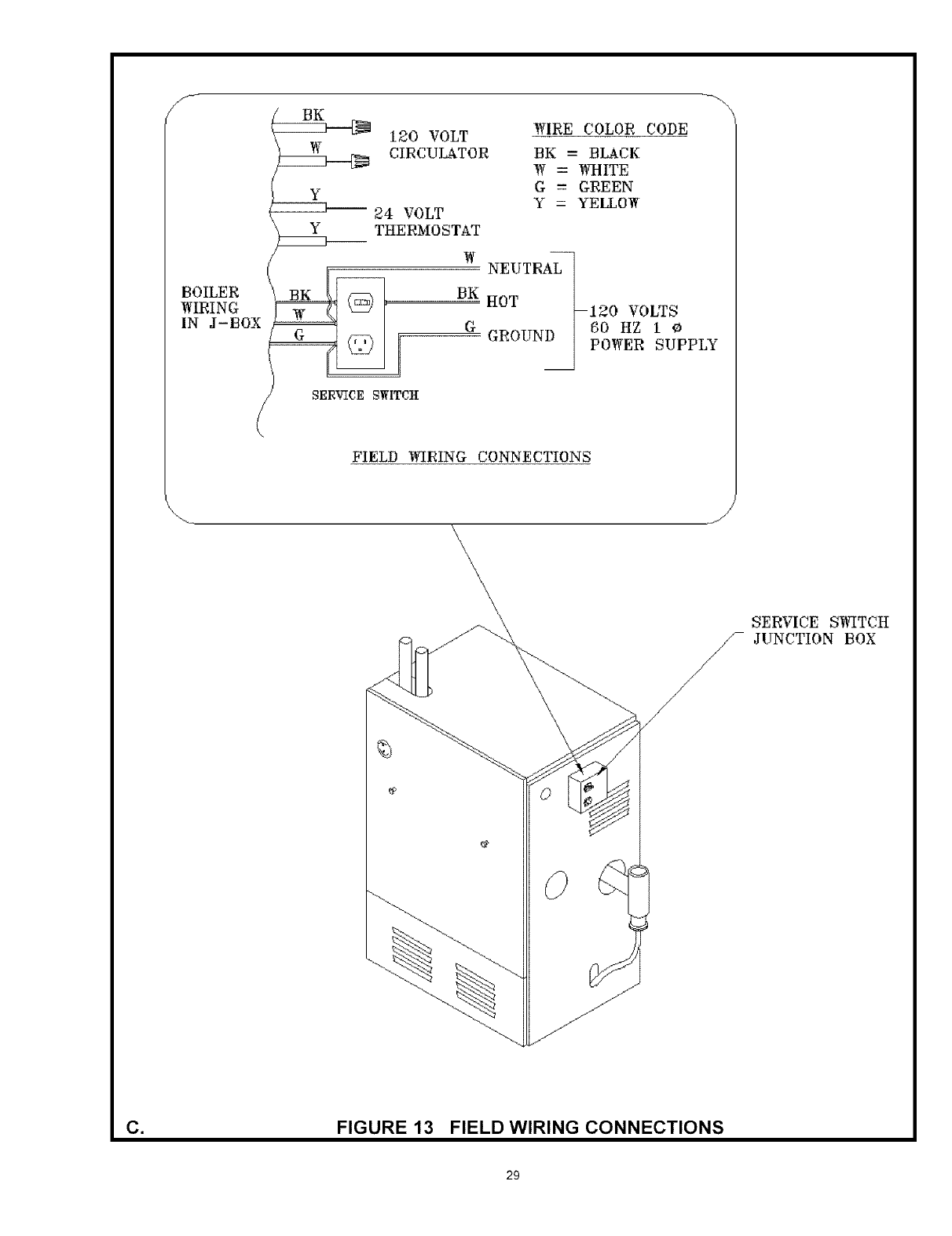
Set heat anticipator at 0.7 amps. Connect 24 volt thermostat leads to the two(2) yellow wires
located in service switch junction box, located on outer jacket of boiler. See Fig. 13 for service
switch junction box and thermostat field wiring connections.
C. Connect Circulator Pump Wiring
See Fig.13 for service switch junction box and circulator pump field wiring connections. A 5 feet
wiring harness with flexible metal conduit is supplied to connect the circulator pump to the ser-
vice switch junction box. If the two 120 volt circulator wire terminals inside the junction box are
not used, please leave the two wire nuts to prevent the short circuit.
CAUTION
LABEL ALL WIRES PRIOR TO DISCONNECTION WHEN SERVICING CONTROLS. WIRING
ERRORS CAN CAUSE IMPROPER AND DANGEROUS OPERATION. VERIFY PROPER
OPERATION AFTER SERVICING.
28
J
BOILER
WIRING
IN J-BOX
120 VOLT
CIRCULATOR
Y
ZzzzD--- 24 VOLT
Y THERMO STAT
W
--i
BK
G
SERVICE SWITCH
WIRE COLOR CODE
BK -- BLACK
W = WHITE
G -- GREEN
Y = YELLOW
NEUTRAL
HOT
GROUND
--120 VOLTS
60 HZ i O
POWER SUPPLY
FIELD WIRING CONNECTIONS
\\\\
\
SERVICE SB_TCH
//_ JUNCTION BOX
/
/
J
jJ
_jJ
C_ FIGURE 13 FIELD WIRING CONNECTIONS
29
z
_2
D"
@
®,
D
If any of the original wire as supplied with this appliance must be replaced, it must be replaced
with type 150°C Thermoplastic wire or its equivalent
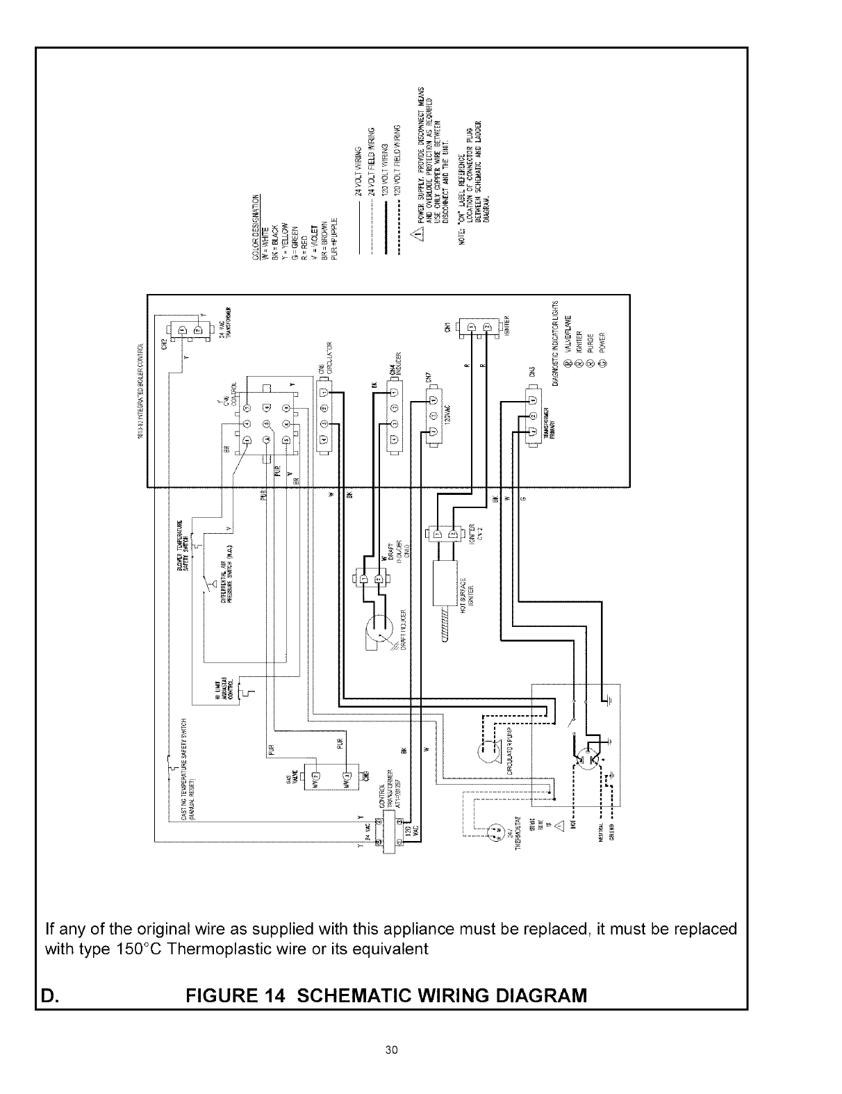
D= FIGURE 14 SCHEMATIC WIRING DIAGRAM
30
P7-1
2K1 P4-I
120 VOLT
POWER SUPPLY
L1
HOT
I
BLK
ON/OFF SWITCH
DRAFT INDUCER
P3-9
P3-7
THERMOSTAT
L2
i
WHT
P7-3
CIRCULATOR MOTOR
ROT SURFACE IGNITER
5K1 P6-1 P12-1 P12-2 PB-2
120 P1-3
P5-3
)>
PI0-2
5K2
H
TRANSFORMER
CASTING TEMPERATURE 2
SAFETY SWITCH
(MANUAL RESET) GAS VALVE
VRB205A
, 4K1 3K1 P3-5 P9-3_ P9-2
r
• P3-1 l
0_c4
@
@ DIFFERENTIAL _jR
@ _ PR EESU RE S_5_lmH
P3-3
A;:LUM,T
QUASTAT
CONTROL 1013-10 CONIROL
_ BLOWER
_" P3-4
<(
P3-2
k_ICROPR OCESSOR
ELECTRONIC
LOGIC _ ]I_ER S
INDICATORLIGHTS 5__
_} POWEN
O PURGE
IGNITER
O M_LVE
O F LA _,'IE
P7-2
../.!_ POWER SUPPLY. PROVIDE
DISCONNECT MEANS AND
OVERLOAD PROTECTION AS
REQUIRED USE ONLY COPPER
WIRE BETWEEN DISCONNECT
AND THE UNIT
NOTE: "P" LABEL REFERENCE
LOCATION OF CONNECTOR PLUG
BETWEEN SCHEMATIC AND
LADDER DIAGRAM
* CAUTION: RECEPTACLE IS LIVE WHEN
BOILER SWITCH IS OFF
--÷_--- REFERENCES PLUG CONNECTION
FIGURE 15 LADDER WIRING DIAGRAM
31

This section provides a brief description of the key controls and accessories found in this boiler.
See the Troubleshooting section of the Service Hints chapter of this installation manual for detailed
sequences of operation and troubleshooting procedures. See the Repair Parts chapter of this manual for
locations of all control components and accessories described.
A. INTEGRATED BOILER CONTROL (IBC)
The Integrated Boiler Control (IBC) is a microprocessor based controller for a high efficiency gas
boiler that monitors all safety controls and which controls the operation of the combustion air blower,
circulator pump, burner, and a combination hot surface igniter/flame sensor. This controller is not
intended for use with a vent damper. This controller is mounted on the control panel inside of the
boiler and contains four (5) diagnostic indicator lights.
B. GAS CONTROL VALVE
The electrically controlled 24 Volt Honeywell Model VR8205 Combination Gas Control Valve is
designed to meet the requirements for use with hot surface ignition systems found in this boiler.
The valve is piped to the gas/air mixer.
C. HOT SURFACE IGNITER
The 120 volt Hot Surface Igniter heats up to 1800 °F to initiate combustion of the gas in the burner.
The igniter is mounted next to the burner through the gas/air mixer. The igniter also serves as a
means for proving the main burner flame by flame rectification. In the event of a lack of flame signal
on three (3) consecutive trials for ignition, the IBC will lockout. The "VALVE" and "FLAME" diagnostic
indicator lamps (lamp "D" and "E" on the IBC, See Fig. 16) wilt blink indicating the failure mode as a
lack of flame signal. The IBC is manually reset from lockout by either removing and reestablishing the
thermostat's call for heat, or by turning the service switch off, then back on.
D. HIGH LIMIT AQUASTAT CONTROL
The High Limit Aquastat Control determines the maximum boiler water temperature and also
provides a means for protecting the boiler and heating system from unsafe operating conditions
which could damage the boiler. The aquastat is mounted in the ½" NPT control well and ¾"x½"
bushing on the top of the front boiler section at the hot water outlet. The aquastat is tied in with the
IBC and is factory set at 180 °F water temperature. The high limit setpoint is field adjustable and may
be set anywhere between 100 °F and 200 °F. The field setpoint adjustment for each installation
depends on heating system requirements. The aquastat automatically resets when the boiler water
temperature decreases (5-30 °F adjustable differential). The differential can be adjusted with the
(white) Differential Adjustment Wheel on the aquastat and gives the flexibility for boiler operation. The
larger the differential, the longer the run cycle of the boiler.
NOTE: The maximum setpoint of the Aquastat must not exceed 200 °F.
E. DRAFT INDUCER TEMPERATURE SAFETY SWITCH
The Draft Inducer Temperature Safety Switch is a disc thermostat (180 °F setpoint) located on the
induced draft fan outlet port. The switch protects the inducer and vent pipe from a potential high
temperature condition for the discharging flue gases. This condition would typically be a result of
higher aquastat setting or over firing. The temperature safety switch automatically resets when the
32
higher aquastat setting or over firing. The temperature safety switch automatically resets
when the vent temperature decreases. (15 °F switch differential).
F. CASTING TEMPERATURE SAFETY SWITCH
In the event of lack of or loss of water in the boiler, the Casting Temperature Safety Switch
(300 °F setpoint) installed on the top of the aluminum boiler section shuts off the boiler by
shutting off power to the Integrated Boiler Control (IBC) and causes the Power Indicator Light
to go out. This fault requires manual reset of the casting temperature safety switch to restart
the boiler. Verify that the boiler is properly filled with water before resetting this switch.
WARNING-Never run cold water into a hot empty boiler.
G. DIFFERENTIAL PRESSURE AIR PROVING SWITCH
The diaphragm type differential pressure switch is connected by vinyl tubing to the pressure
signal hose adapters. The pressure switch monitors air flow by sensing the diffential
pressure measured in inches of water(" w.c.). The factory settings on these switches are
1.00 "w.c. for Model-100, 1.35 "w.c. for Model-75 and 1.55 "w.c. for Model-50. The contacts
are normally open, and close when the draft inducer is running and causing the diffential
pressure at the switch to exceed the setting. The closed switch proves there is adequate air
flow for combustion. The pressure switch shuts off the main burner if the differential pressure
is inadequate due to a blocked vent pipe or a blocked air intake or blocked boiler sections or
blocked draft inducer. After five (5) minutes of lack of the adequate differential pressure, the
IBC will lockout. The "PURGE" indicator light will blink, indicating a failure to prove adequate
combustion air flow or flue gas flow. The IBC is manually reset from lockout as described in
the Sequence of Operation section of this chapter.
H. DRAFT INDUCER
The draft inducer (blower) provides a means for pulling combustion air into and through the
mixer, the burner, the flue ways of the cast aluminum boiler sections and the flue adapter
before being discharged through the vent piping to the outdoors. See applicable sections for
proper sizing and installation of combustion air and vent piping in this manual.
CIRCULATOR PUMP
Every forced hot water system requires at least one circulating pump. The circulating pump
imparts the necessary energy to move the water through the closed loop supply and return
piping systems, terminal heating equipment (i.e. finned tube radiators, etc.) and back
through the boiler for reheating. To provide the required hot water flow rates, the circulator
pump must be properly sized to overcome frictional losses (usually measured in feet of
water, also referred to as "pump head loss") of the supply and return piping systems and
boiler. The circulator pump is furnished in a carton within the boiler cabinet for a single zone
or zone valve controlled heating system and should be correctly located on the downstream
(i.e., pumping away) side of the expansion tank. For a pump controlled system (where there
is a circulator for each zone) the circulator provided with the boiler can work for one zone.
For more details on piping and circulators, see Near Boiler Piping section of this manual.
J. DRAIN VALVE
The manual drain valve provides a means of draining the water in the heating system, including
the boiler and hot water supply and return piping systems installed above the drain valve. This
drain valve is installed in the 3/4" tapping at the bottom of the front boiler section. Any piping
installedbelow the elevation of this drain valve will require additional drain valves to be installed
at low points in the piping systems in order to drain the entire system.
33
K. A.S.M.E. RATED PRESSURE RELIEF VALVE
Each boiler must have a properly sized and installed American Society of Mechanical Engi-
neers rated pressure relief valve. Water expands as it is heated by the burner/boiler sections.
If there is no place for the water to expand its volume, (i.e. a properly sized and properly
functioning expansion tank) pressure on the inside of the boiler and heating system will
increase. The furnished relief valve will automatically open at 30 psig pressure to relieve the
strain on the boiler and heating system from the increasing pressure. The pressure relief
valve discharge must be piped with piping same size as the valve discharge opening to an
open drain, tub or sink, or other suitable drainage point not subject to freezing, in accordance
with A.S.M.E. specifications. Failure to provide the pressure relief valve with piping as herein
described may cause water damage and/or serious bodily injury. The boiler manufacturer is
not responsible for any water damage or personal injury.
L. FLAME ROLLOUT SAFETY SHUTOFF
As required, this boiler is equipped with a manual reset flame rollout safety shutoff means,
which shuts off main burner gas in the event that the flow of combustion products through
the flueways is reduced. In the event of blocked flueways, enough air will not be available to
support combustion, and the $9301 Integrated Boiler Control (IBC) will lockout due to loss of
adequate air flow (after 3 trials for ignition). The "PURGE" diagnostic indicator lamp (lamp "B"
on the IBC, see Fig.16) will blink indicating the failure mode as a lack of adequate air flow.
The IBC is manually reset from lockout by either removing and reestablishing the
thermostat's call for heat, or by turning the service switch off, then back on. If the boiler
cannot be restored to normal operating condition by resetting the control, contact a qualified
service agency to check heat exchanger flueways for blockage.
M. (OPTIONAL) EXTERNAL CONDENSATE PUMP
For installations where there is no floor drain or other appropriate drainage receptacle avail-
able to receive condensate from the boiler, an external float activated condensate pump with
integral sump is required. This unit can be installed to pump the condensate to a remote tie
in point to a sanitary sewer system. For this application, the boiler must be installed so that
proper pitch of piping to the external condensate reservoir (sump) can be accomplished. Use
wood frame or blocks to raise boiler as required for proper installation.
A. WATER TREATMENT AND FREEZE PROTECTION
.When filling the boiler and heating system, water treatment is generally not required or
desired. For localities where the water is unusually hard (above 7 grains hardness) or for
low pH water conditions (below 7.0), consult a local water treatment specialist.
a. This boiler is designed for use in a closed hydronic heating system ONLY!
b. Excessive feeding of fresh make-up water to the boiler may lead to premature failure
of the boiler sections.
.Use clean fresh tap water for initial fill and make-up of boiler.
a. A sand filter must be used if fill and make-up water from a well is to be used.
b. Consideration should be given to cleaning the heating system, particularly in
retrofit situations, where a new boiler is being installed in an older piping system.
34
c. In older system, obviously discolored, murky, or dirty water, or a pH reading below 7, are
indications that the system should be cleaned.
d. A pH reading between 7 and 8 is preferred.
3. Antifreeze if needed, must be of a type specifically designed for use in closed hydronic heating
systems and with aluminum.
a. Choice and use of antifreeze must be in accordance with local plumbing codes.
b Only INTERCOOL NFP-50 is approved for use.
• Use of any antifreeze other than INTERCOOL NFP-50 will void warranty.
• Antifreeze must be maintained per manufacturers specifications, failure to do so will
result in the warranty being voided.
c. Do not use automotive antifreeze as the type of corrosion inhibitors used will coat the boiler's
heat transfer surfaces and greatly reduce capacity and efficiency.
d. Consult antifreeze manufacturer's literature for compatibility of antifreeze with
aluminum boiler. For approved manufactured antifreeze (INTERCOOL NFP-50 Coolant)
please contact Interstate Chemical Co. New York Customer Service at 1-800-422-2436.
Some brands have corrosion inhibitors that break down more rapidly or become ineffective at
higher operating temperatures when used with aluminum. Follow the antifreeze manufacturers
instructions on determining the proper ratio of antifreeze to water for the expected low
temperature conditions, and for maintaining the quality of the antifreeze solutions from year to
year.
e. Use of antifreeze in any boiler will reduce capacity by as much as 10 to 20%, due to differing
heat transfer and pumping characteristics. This must be taken into consideration when sizing
the heating system, pump(s), and expansion tank. Consult antifreeze manufacturer's literature
for specific information on reduced capacity.
f. Water content of the boiler is 2.6 gallons. (10 liters)
B. FILLING BOILER WITH WATER AND PURGING ARE FOR SYSTEMS WITH DIAPHRAGM
TYPE EXPANSION TANKS.
Refer to appropriate "Near Boiler Piping" diagrams.
1. Close all zone service valves on the supply and return piping. Open the feed valve and fill boiler
with water. Make sure air vent is open. Hold relief valve open until water runs air free for five
seconds to rapidly bleed air from boiler, then let the relief valve snap shut.
2. Open the zone service valve on the SUDDIv pipe for the first zone. Open the purge valve on the
first zone. Feed water wilt fill the zone, pushing air out the purge valve. Close the purge valve
when the water runs air free. Close the zone service valve.
3. Repeat step 2 for all remaining zones.
4. Open all service valves. Any air remaining trapped in the return lines between the service valves
and the boiler will be pushed towards the air vent when the boiler is placed in operation.
5. Inspect piping system. Repair any leaks immediately.
C. FILLING BOILER WITH WATER AND PURGING AIR FOR SYSTEMS WITH
CONVENTIONAL CLOSED TYPE EXPANSION TANKS
Refer to appropriate "Near Boiler Piping" diagrams.
1. Close all zone service valves on the supply and return piping and close the expansion tank service
valve. Drain expansion tank. Open the feed valve and fill boiler with water. Hold relief valve open
until water runs air free for five seconds to rapidly bleed air from boiler, then let the relief valve
snap shut.
2. Open the zone service valve on the SUDDIv pipe for the first zone. Open the purge valve on the
first zone. Feed water will fill the zone, pushing air out the purge valve. Close the purge valve
when the water runs air free. Close the zone service valve.
3. Repeat step 2 for all remaining zones.
35
4. Open the expansion tank service valve and the tank vent. Fill the tank to the proper level
and close the tank vent. Remove the handle from the expansion tank service valve so
the homeowner doesn't accidentally close it.
5. Open all service valves. Any air remaining trapped in the return lines between the
service valves and the boiler will be pushed towards the expansion tank when the boiler
is placed in operation.
6. Inspect piping system. Repair any leaks immediately.
NOTE: DO NOT use stop leak compounds. Leaks in threaded connections in the
aluminumboiler sections must be repaired immediately. Aluminum threads will not
seal themselves.
D. PLACING BOILER IN OPERATION
FOR YOUR SAFETY READ BEFORE OPERATING
I
WARNING: If you do not follow these instructions exactly, a fire or explosion I
may result causing property damage, personal injury or loss of life I
This appliance is equipped with an ignition device which
automaticaJly lights the pilot Do not try to light the pilot
by hand
BEFORE OPERATING smefl a]l around the appliance
area for gas Be sure to smell next to the floor because
some gas is heavier than air and will setfle on the floor
WHAT TO DO IF YOU SMELL GAS
Do not try to ]ight any appliance
Do not touch any electrical switch: do not use any phone
in your building
Immediately call your gas supplier from a neighbor's
phone Follow the gas supplier's instructions
If you cannot reach your gas supplier, call the fire
department
Use only your hand to move the system control switch
Never use tools If the switch wifl not move by hand,
don't try to repair it, call a qualified service technician
Force or attempted repair may result in a fire or
explosion
Do not use this appliance if any part has been under
water Immediately call a qualified service technician
to inspect the appliance and to replace any part of the
control system and any gas control which has been
under water
1STOP! Read the safety information above on this label
2 Set thermostat to lowest setting
3 Turn off all electric power to the appliance
4 This appliance is equipped with an ignition device which
automatically lights the burner DONOT try to light the
burner by hand
OPERATING INSTRUCTIONS
5 Remove the front jacket panel
6 Turn the gas control knob clockwise _ to "OFF"
7 Wait five (5) minutes to clear out any gas Then smell for
gas, including near the floor If you smell gas, STOP!
Follow "B" in the safety information above on this label If
you don't smell gas go on to next step
8 Turn the gas control knob counter clockwise _ to
"ON"
9 Replace front jacket panel
10 Turn on all electrical power to the appliance
11 Set the thermostat to desired setting
12 If the appliance wifl not operate foNowthe instructions "To
Turn Off Gas To Appliance" and call your service technician
or gas supplier
TO TURN OFF GAS TO APPLIANCE
1 Set the thermostat to lowest setting
2 Turn off all electric power to the appliance if service is to
be preformed
3 Remove the front jacket panel
4 Turn gas control knob clockwise __ to "OFF"
5 Replace the front jacket panel
Safe lighting and other performance criteria were met with the gas manifold and control assembly
provided on the boiler when the boiler underwent tests specified in ANSI Z21.13-latest revision.
36
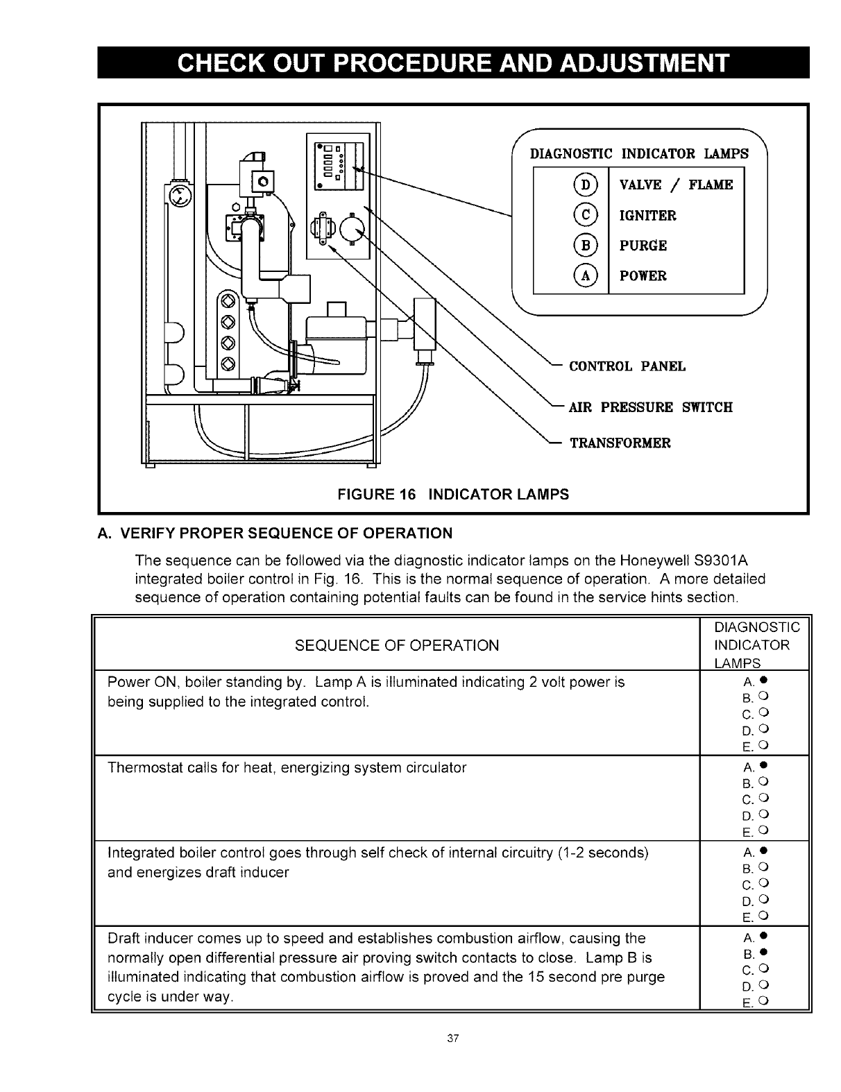
DIAGNOSTIC INDICATOR LAMPS
®
©
®
®
VALVE /FLAME
IGN_ER
PURGE
POWER
CONTROL PANEL
MR PRESSURE SWITCH
TRANSFORMER
FIGURE 16 INDICATOR LAMPS
A. VERIFY PROPER SEQUENCE OF OPERATION
The sequence can be followed via the diagnostic indicator lamps on the Honeywell $9301A
integrated boiler control in Fig. 16. This is the normal sequence of operation. A more detailed
sequence of operation containing potential faults can be found in the service hints section.
DIAGNOSTIC
SEQUENCE OF OPERATION INDICATOR
LAMPS
Power ON, boiler standing by. Lamp A is illuminated indicating 2 volt power is A. •
being supplied to the integrated control. B. O
C.O
DO
E O
Thermostat calls for heat, energizing system circulator A. •
B O
C.O
DO
E O
Integrated boiler control goes through self check of internal circuitry (1-2 seconds) A. •
and energizes draft inducer B. O
C.O
DO
E O
Draft inducer comes up to speed and establishes combustion airflow, causing the A. •
normally open differential pressure air proving switch contacts to close. Lamp B is B. •
illuminated indicating that combustion airflow is proved and the 15 second pre purge C. o
DO
cycle is under way. E. O
37
After pre purge, Lamp B goes out and Lamp C illuminates, indicating the hot surface
igniter is powered for the 20 second igniter warm-up period. The bright yellow orange
glow of the hot surface igniter can be observed through the observation port in the
front boiler section just above the igniter.
After igniter warm-up, the gas valve is energized, and opens on the normal firing rate
regulator (2.5" w.c.) for a 6 second trial for ignition. Lamp D illuminates. The blue orange
glow of the burner can be seen through the observation port.
Two seconds later, Lamp C goes out as power is turned off to the hot surface igniter.
During the last two seconds of the 6 seconds trial for ignition, main burner flames is
proven by flame rectification through the hot During surface igniter, providing flame
rectification to the integrated boiler control and fully illuminating Lamp E.. The gas valve
remains energized, and the boiler runs.
Thermostat ends call for heat, de-energizing gas valve and system circulator. Burner
stops firing, and Lamp D goes out. Draft inducers remains powered. Lamp B illuminates,
indicating draft inducer is running for 30 second postpurge.
After 30 seconds, draft inducer is de-energized Lamp B goes out. Boiler stands by for
next call for heat.
A.O
B.O
C.O
D.O
E.O
A.O
B.O
C.O
D.O
E.®
A.O
B.O
C.O
D.O
E.O
A.O
B.O
C.O
D.O
EO
A.O
B.O
C.O
D.O
E.O
NOTE: First couple of cold starts may be rough due to gas line not being completely purged
of air, causing low firing rate and high excess air levels..
B. INSPECT VENTING AND AIR INTAKE SYSTEM
Operate the boiler and verify that all vent/air intake connections are gastight and watertight.
Repair any leaks immediately.
C. INSPECT CONDENSATE DRAIN
Verify that all connections are watertight, and that condensate flows freely. Repair any leaks
immediately.
D. INSPECT SYSTEM PIPING
Verify that all connections are watertight. Repair any leaks immediately.
E. TEST IGNITION SYSTEM SAFETY SHUTOFF DEVICE
1. Turn off manual gas valve
2. Set thermostat to call for heat
3. Boiler begins normal sequence of operation
4. After approximately 40 seconds (pre purge and igniter warm-up period), lamp D illumi
nates, indicating gas valve is powered
5. After 6 seconds, gas valve closes, lamp D goes out as integrated boiler control senses
that flame is not present
6. To restart system, follow operating instructions under "START-UP PLACE IN OPERATION"
38
F. TEST HIGH LIMIT CONTROL AND ADJUST
While burner is operating, move indicator on high limit control below actual boiler water
temperature. Burner should go off while circulator continues to operate. Raise limit setting
above boiler water temperature and burner should reignite after pre purge and igniter warm-
up period. Set the high limit control to the design temperature requirements of the system.
Maximum high limit setting is 200°F. Minimum high limit setting is 100°F.
G. TEST OTHER SAFETY CONTROLS
If the boiler is equipped with a low water cut off, a manual reset high limit, or additional safety
controls, test for operation as outlined by the control manufacturer. Burner should be operat-
ing and should go off when controls are tested. When safety controls are restored, burner
should reignite.
H. SET THERMOSTAT HEAT ANTICIPATOR (IF USED) AND VERIFY THERMOSTAT OPERATION
For a single thermostat connected to the yellow thermostat lead wires in the furnished field
wiring junction box, the heat anticipator should be set at 0.7 amps. For other wiring configura-
tions, refer to the instructions provided by the thermostat manufacturer regarding adjustment
of heat anticipator. Cycle boiler with thermostat. Raise the thermostat to the highest setting
and verify boiler goes through normal start up cycle. Lower thermostat to lowest setting and
verify boiler goes off.
MEASURE THE NATURAL GAS INPUT RATE
Correct input rate is essential for proper and efficient operation of the burner and boiler.
1. Determine elevation at installation site.
2. See page 4 and 5 of this manual to determine the correct input rate for the local elevation.
3. Obtain the yearly average heating value of the local gas supply from the gas utility. At sea
level elevation, it should be approximately 1000 Btu's per standard cubic foot.
4. Operate boiler for 5 minutes.
5. Turn off all other gas appliances, extinguishing standing pilots where applicable.
6. At gas meter, measure time in seconds required to use one cubic foot of gas.
7. Calculate input rate according to the following formula:
3600xheatinq value from step 3
B tuh input rate =time from step 6
.Measured input rate should be within +/-2% of the input rating from step 2. If within 2%, go
to step 9. If not, adjustment is required, proceed as follows:
a. Turn boiler off
b. Set up U-tube manometer or differential pressure gauge for measuring manifold pres
sure, see FIG. 17.
c. Manometer or gauge must be able to read at least 0.0 to 3.0 inches water column of
pressure, and resolve to at least 0.1 inches water column.
d. Turn boiler on.
e. Manifold pressure has been nominally set at 2.5 inches w.c. Manifold pressure and input
rate must always be measured with pressure regulator cover screw installed..Cover screw
must be removed for adjustment. Manifold pressure reading will change (increase) when
cover screw is removed.
39
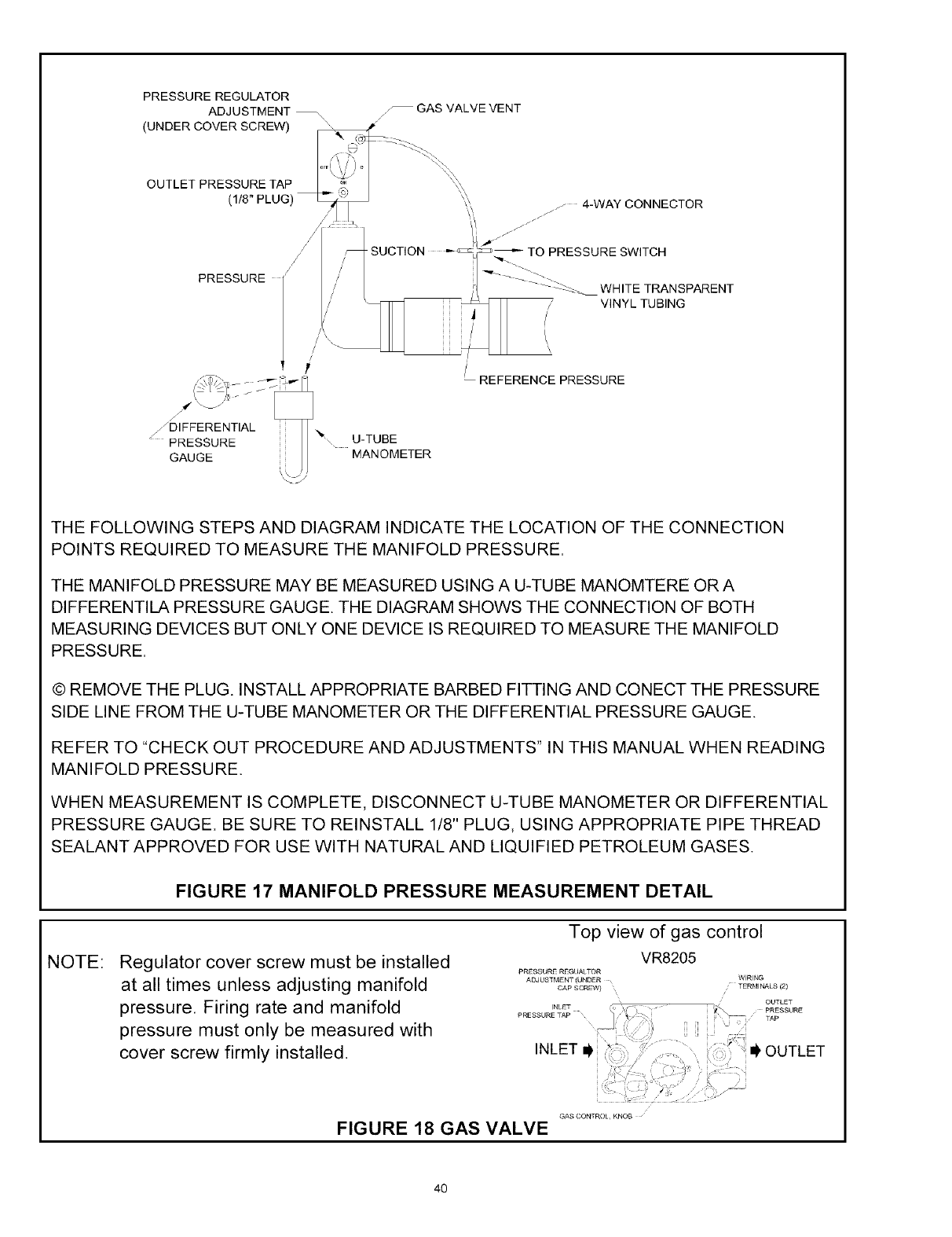
PRESSURE REGULATOR
ADJUSTMENT_
(UNDER COVER SCREW) ",
_--GAS VALVE VENT
j/
OUTLET PRESSURE TAP
(1/8" PLUG)
PRESSURE
...._DIFFERENTIAL
: PRESSURE
GAUGE
%' U-TUBE
MANOMETER
_ 4-WAY CONNECTOR
J
WHITE TRANSPARENT
VINYL TUBING
\
/REFERENCE PRESSURE
THE FOLLOWING STEPS AND DIAGRAM INDICATE THE LOCATION OF THE CONNECTION
POINTS REQUIRED TO MEASURE THE MANIFOLD PRESSURE•
THE MANIFOLD PRESSURE MAY BE MEASURED USING A U-TUBE MANOMTERE OR A
DIFFERENTILA PRESSURE GAUGE. THE DIAGRAM SHOWS THE CONNECTION OF BOTH
MEASURING DEVICES BUT ONLY ONE DEVICE IS REQUIRED TO MEASURE THE MANIFOLD
PRESSURE•
© REMOVE THE PLUG• INSTALL APPROPRIATE BARBED FITTING AND CONECT THE PRESSURE
SIDE LINE FROM THE U-TUBE MANOMETER OR THE DIFFERENTIAL PRESSURE GAUGE.
REFER TO "CHECK OUT PROCEDURE AND ADJUSTMENTS" IN THIS MANUAL WHEN READING
MANIFOLD PRESSURE.
WHEN MEASUREMENT IS COMPLETE, DISCONNECT U-TUBE MANOMETER OR DIFFERENTIAL
PRESSURE GAUGE. BE SURE TO REINSTALL 1/8" PLUG, USING APPROPRIATE PIPE THREAD
SEALANT APPROVED FOR USE WITH NATURAL AND LIQUIFIED PETROLEUM GASES.
NOTE:
FIGURE 17 MANIFOLD PRESSURE MEASUREMENT DETAIL
Regulator cover screw must be installed
at all times unless adjusting manifold
pressure. Firing rate and manifold
pressure must only be measured with
cover screw firmly installed.
Top view of gas control
VR8205
PRESSURE REGUAITOR
ADJUSTMENTIUNDER
CAPSCREW)
INLET
PRESSURETAP
INLET i_
WIRING
TERMINALS (2)
OUTLET
PRESSURE
TAP
: _ OUTLET
?
GAS CONTROl KNOB
FIGURE 18 GAS VALVE
40
I. Remove regulator cover screw on top of gas valve, and insert an appropriate screw-
driver into adjustment screw.
II. Turn adjustment screw clockwise to increase input rate, or counter clockwise to de-
crease input rate.
III. Replace cover screw, or cover hole temporarily with your finger to check new mani-
fold pressure setting. Do not set manifold pressure lower than 2.0 inches w.c. or
higher than 3.0 inches w.c. when adjusting input rate.
IV. Measure new input rate (cover screw must be installed). Repeat steps I.-IV until the
input rate is within +/-2% of the nameplate input rating.
V. If the actual input rate can not be set to within 2% of the correct input rating by adjust-
ing manifold pressure, a change in gas orifice size is required. Consult the boiler
manufacturer for information on correct orifice sizing. The specific gravity (G) and the
higher heating value (HHV) of the local natural gas must be obtained from the local
gas utility in order to determine the proper orifice size.
f. After adjusting input rate, turn boiler off, remove manometer or pressure gauge, reinstall
1/8" plug on gas valve. Turn boiler on.
9.Restore all gas appliances that may have been shut off (while measuring boiler input
rate) to normal operating conditions.
J. SET THERMOSTAT TO DESIRED ROOM TEMPERATURE
Observe several operating cycles to verify proper operation.
K REVIEW ALL INSTRUCTIONS
Review all instructions shipped with this boiler with owner or maintenance person. Instructions
must be affixed on or adjacent to the boiler.
L. COMPLETE AND SIGN THE INSTALLATION AND CHECK-OUT CERTIFICATE ON THE
FOLLOWING PAGE.
41
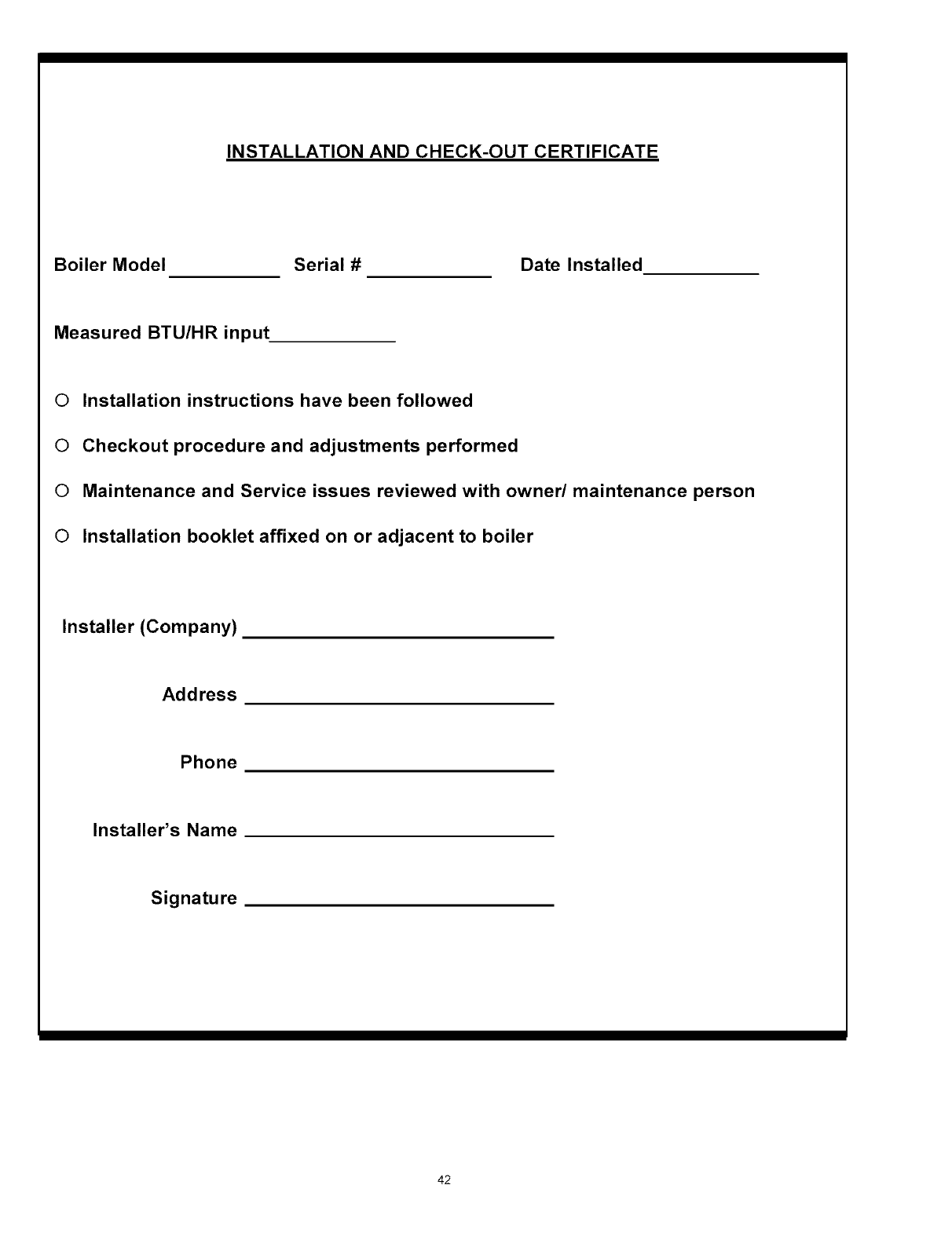
INSTALLATION AND CHECK-OUT CERTIFICATE
Boiler Model Serial # Date Installed
Measured BTU/HR input
©Installation instructions have been followed
©Checkout procedure and adjustments performed
©Maintenance and Service issues reviewed with owner/maintenance person
©Installation booklet affixed on or adjacent to boiler
Installer (Company)
Address
Phone
Installer's Name
Signature
42
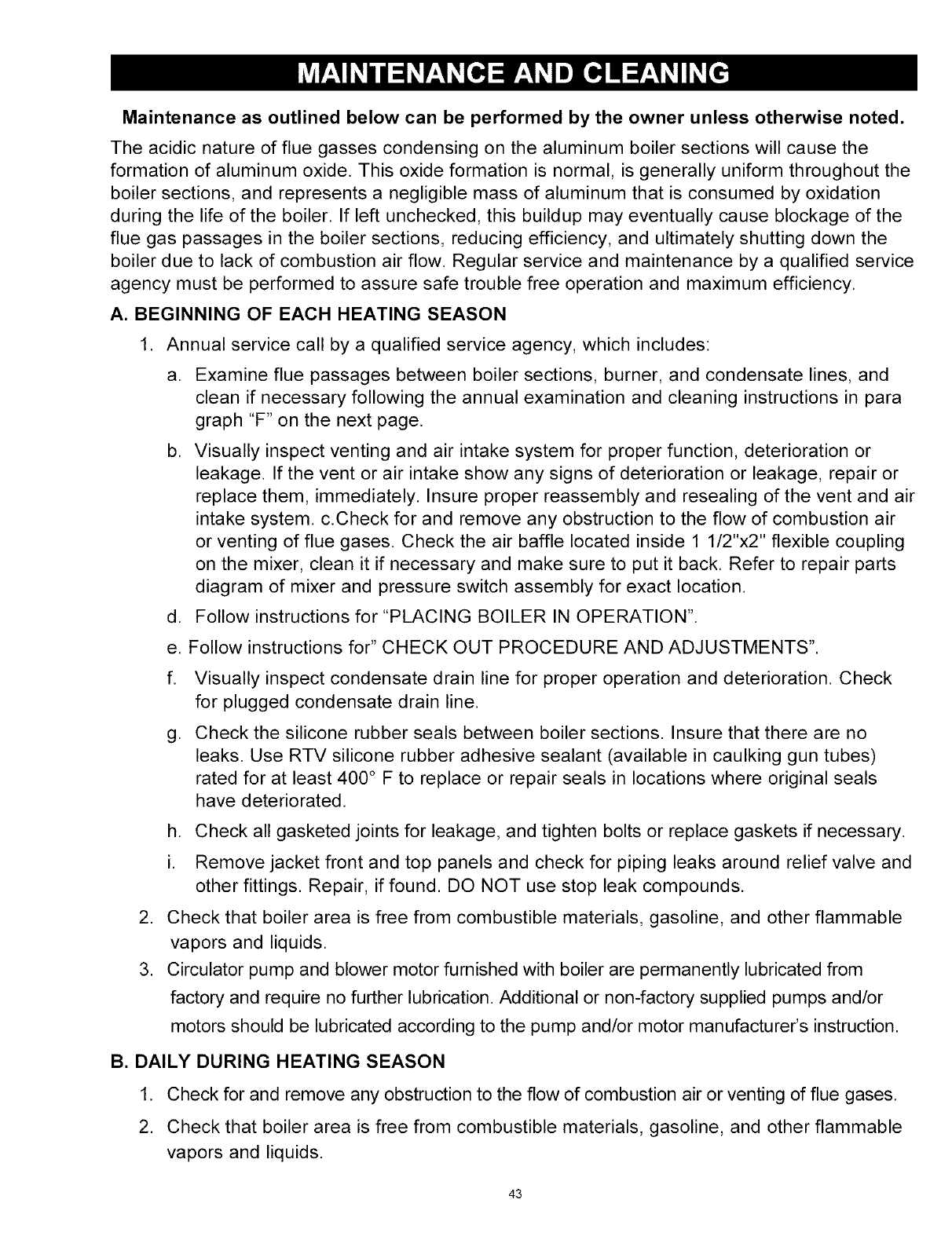
Maintenance as outlined below can be performed by the owner unless otherwise noted.
The acidic nature of flue gasses condensing on the aluminum boiler sections will cause the
formation of aluminum oxide. This oxide formation is normal, is generally uniform throughout the
boiler sections, and represents a negligible mass of aluminum that is consumed by oxidation
during the life of the boiler. If left unchecked, this buildup may eventually cause blockage of the
flue gas passages in the boiler sections, reducing efficiency, and ultimately shutting down the
boiler due to lack of combustion air flow. Regular service and maintenance by a qualified service
agency must be performed to assure safe trouble free operation and maximum efficiency.
A. BEGINNING OF EACH HEATING SEASON
,Annual service call by a qualified service agency, which includes:
a. Examine flue passages between boiler sections, burner, and condensate lines, and
clean if necessary following the annual examination and cleaning instructions in para
graph "F" on the next page.
b. Visually inspect venting and air intake system for proper function, deterioration or
leakage. If the vent or air intake show any signs of deterioration or leakage, repair or
replace them, immediately. Insure proper reassembly and resealing of the vent and air
intake system, c.Check for and remove any obstruction to the flow of combustion air
or venting of flue gases. Check the air baffle located inside 1 1/2"x2" flexible coupling
on the mixer, clean it if necessary and make sure to put it back. Refer to repair parts
diagram of mixer and pressure switch assembly for exact location.
d. Follow instructions for "PLACING BOILER IN OPERATION".
e. Follow instructions for" CHECK OUT PROCEDURE AND ADJUSTMENTS".
f. Visually inspect condensate drain line for proper operation and deterioration. Check
for plugged condensate drain line.
g. Check the silicone rubber seals between boiler sections. Insure that there are no
leaks. Use RTV silicone rubber adhesive sealant (available in caulking gun tubes)
rated for at least 400 ° F to replace or repair seals in locations where original seals
have deteriorated.
h. Check all gasketed joints for leakage, and tighten bolts or replace gaskets if necessary.
i. Remove jacket front and top panels and check for piping leaks around relief valve and
other fittings. Repair, if found. DO NOT use stop leak compounds.
2. Check that boiler area is free from combustible materials, gasoline, and other flammable
vapors and liquids.
3. Circulator pump and blower motor furnished with boiler are permanently lubricated from
factory and require no further lubrication. Additional or non-factory supplied pumps and/or
motors should be lubricated according to the pump and/or motor manufacturer's instruction.
B. DAILY DURING HEATING SEASON
1. Check for and remove any obstruction to the flow of combustion air or venting of flue gases.
2. Check that boiler area is free from combustible materials, gasoline, and other flammable
vapors and liquids.
43
C. MONTHLY DURING HEATING SEASON
1. Remove jacket front and top panels and check for piping leaks around relief valve and
other fittings. If found, contact a qualified service agency to repair. DO NOT use stop leak
compounds.
2. Test relief valve. Refer to valve manufacturers instructions packaged with relief valve.
3. Visually inspect venting and air intake system for proper function, deterioration, or
leakage. If the vent or air intake show any signs of deterioration or leakage, contact a
qualified service agency to repair or replace them immediately and to insure proper
reassembly and resealing of the vent and air intake system.
4. Visually inspect the clear vinyl condensate lines and the PVC condensate drain pipe for
proper operation, leakage, and deterioration. If the condensate lines or drain pipe show
any signs of blockage, leakage, or deterioration contact a qualified service agency to
clean, repair, or replace them immediately.
5. Check the air baffle located inside 1 1/2"x 2" flexible coupling, clean it if necessary and
make sure to put it back. Refer to repair parts diagram, mixer and pressure switch
assembly.
D. PERIODICALLY DURING HEATING SEASON
1. Where low water cut offs are used, a periodic inspection of the low water cut off is
necessary, including flushing of float type devices. Refer to low water cut off
manufacturer's specific instructions.
E. END OF EACH HEATING SEASON - ANNUAL SHUTDOWN PROCEDUR
1. Follow instructions "TO TURN OFF GAS TO APPLIANCE".
2. If heating system is to remain out of service during freezing weather, and does not contain
antifreeze, drain system completely. If boiler will be exposed to freezing temperatures,
drain condensate lines. Otherwise, do not drain system or boiler.
F. ANNUAL EXAMINATION AND CLEANING OF BOILER COMPONENTS
The following service procedures must be performed only by a qualified service
agency. Boiler owner should not attempt these procedures.
1. Before Servicing, turn off electrical power to boiler at service switch. Close manual gas
valve to turn off gas supply to boiler.
2. Cleaning Flue passages between boiler sections.
&Any buildup of sediment or aluminum oxide (white powdery or flaky substance) in the
flue passages must be cleaned as follows:
b.Remove jacket front and top panels. Disconnect condensate drain line from the barbed
fitting on the bottom of the boiler. Keep the open end of the drain line above the water
level in the condensate trap to prevent the trap from draining. Disconnect pressure switch
hose from barbed fitting on gas valve. Disconnect 11/=x 2" flexible coupling from air inlet.
Disconnect air by-pass (½" transparent vinyl tube) from the bottom of the mixer.
44
,
c,
d,
e,
f.
g.
Remove air baffle from 1%z" x2" flexible coupling and clean air baffle if necessary.
Refer to repair parts diagram, mixer and pressure switch assembly.
Confirm that manual gas valve is closed and disconnect gas line to gas valve at union.
Disconnect wires to gas valve, and igniter.
Loosen but do not remove five (5) nuts attaching mixer assembly to boiler. Remove
two (2) igniter screws and very carefully remove the igniter. Use care when removing
the igniter, it is very brittle!!
Remove five (5) nuts and remove mixer assembly. Remove burner and mixer gasket.
Aluminum oxide deposits are water soluble and may be rinsed away with spraying or
running water. Before rinsing, connect a '/z" I.D. hose to the barbed fitting on the
bottom of the boiler and run the hose to a bucket or drain.
h. After rinsing, remove any remaining loosened sediment using a shop vacuum with a
snorkel attachment.
J,
k.
Inspect burner for any foreign matter in the flame ports or inside the burner. Any for-
eign matter should be removed by blowing with compressed air or vacuuming.
Inspect interior of mixer for any signs of sediment or aluminum oxide and clean if necessary.
Reinstall burner and mixer gasket and position mixer assembly over studs. Install five
(5) nuts but do not tighten. Reinstall igniter and igniter gasket and fasten with two (2)
screws. Use care when installing the igniter. It is very brittle!! Tighten five (5) nuts
holding mixer assembly.
Connect:
• gas line to gas valve
• condensate drain line to boiler
• pressure switch hose to gas valve
• air by-pass to mixer
• 1 1/2" x2" flexible coupling to air inlet and make sure to put air baffle back to
correct position
•igniter wires
• gas valve wires
Visually inspect condensate lines leading from the boiler sections and the vent tee to the
condensate trap. Refer to repair parts diagrams. Any foreign material or debris that is
visible in the condensate lines needs to be cleaned out as follows:.
a. Raise condensate trap and drain condensate lines completely.
b. Once the condensate trap is emptied of water, disconnect condensate lines from the
fittings on the boiler, the vent tee, and the condensate outlet.
c. Remove the condensate trap and run cold water through the condensate lines to
thoroughly flush out any sediment or debris in the lines.
45
d. Reinstall and connect the condensate trap, using the hose clamps to secure the various
condensate lines to their fittings.
e. Follow the instructions under "NEAR BOILER PIPING" for"filling condensate trap with
water"
4. Inspection of the flue connector requires the following steps (Refer to the repair parts diagram.)
a. Loosen the clamp on the draft inducer end of the 2" flexible coupling that connects the
vent tee to the draft inducer. Disconnect (unplug) wiring harness from draft inducer motor
and draft inducer temperature safety switch. Remove four (4) bolts that attach draft in
ducer to flue connector.
b. Remove draft inducer and gasket from top of flue connector.
C. Inspect interior of flue connector. Any buildup of sediment or aluminum oxide on the
inside surface must be cleaned. Position the draft inducer gasket and the draft inducer
and fasten with four (4) screws. Be sure to connect ground wire from draft inducer motor
to one of the four mounting screws.
d. Connect wiring harness leads to the draft inducer motor and the draft inducer tempera
ture safety switch.
e. Connect the 2" flexible coupling to the draft inducer outlet.
46
P O_ll ER ON
STA ND BY
4,
THERMOSTAT
CALLS FOR HEAT
CIRCULATOR
ENERGIEES THRU
2K1 CONTACTS
4,
ISC SELFCHECK OF
INTERNAL CIRCUITRY'
1-2 SEC
J CHECKS
E/_ N O. AIR
",, PRESSURE
'_ SWITCH
CONTACTS
PEN
DRAFTINDUBER
ENERGEES THRU
IKI CONTACTS
// IBC \
WAITS FOR
UP TO 5 MINUTES
\
f \
"\. /
"--.. /
OPEN
CONTROL LOCKOUT PURGE LIGHT
BLI;1KS, RESET REQUIRED CIRCULATOR
REMAINS ENERGEED AS LONG AS
TH ER M OSTAT C ONTIN URES TO CA LL FOR
HEAT
PURGE LIGHT ISO;1, AIRFLOW PROVED.
DRAFT INDUCER RUNS FOR I5 SEC PREPURGE
_V
!F2""-,
// POSITIVE ",
PROOF OF ",,
IF MAIN BURNER DOESNOTPROVE
FLAME IN 3 TRIALS, CONTROL
LOCKOUT VALVEIFLAME LIGHT RLINKS ,
RESET IS REQUIRED THIS PROBLEMISA
RESULT OF NOT ESTABLISHINGFLAME SIG1"_AL
CONTROL WILL A F]'EMPT 2
A DDITTIONAL IGNITION SEQUENSES
STA RTING WITH PREPURGE
BED
DURING THE LAST 2 BEG OFTHE5SEC IGNITION
TRIAL MAIN BURNER FLAME IS PROVED BY FLAME
RECTIFICATION A FLAME SIGNALTOIBC GASVALVE
REMAINS ENERGIZED BOILER RUNS
2 SEC INTO THE 5 SEC IGNITION TRIAL PC¢_llER
IS-[URNED OFF TOTHE HOT SURFACEIGNITER.
1G;t ITER LIGHT IS OFF.
GAS VALVE OPENS FOR 5SEGTR_LFOR
IGNI]ION. BLUE ORANGE GLOW C_]HE BURNER
CAN BE SEEN THRU OBSERVATION PORT
GAS VALVE ENERGEED 1NR U 3}<,1 AN D 4K 1.
CONTADTS, VALVE LIGHTtS ON.
PURGE LIGHT GOES OUT HQTSURFACEIG_ITER
POWERED THRU 5KI 5K2CONTACTSFOR2O
SEC IGNITER WARMUP BRIGHTYELLOW
ORANGE GLOW OF THE HOT SURFACEIGNITER
CAN BE OBSERVED THRU THE OBSERVATION
PORT IN FRONT OF BOILER SECTION JUST
ABOVE IGNITER, IG;11TOR LIG;1TIS O;1
MAIN \
SURNER PROVE \\YEB_ [ NORMAL
FLAME WITHIN INITIAL /,,;_ OPERATION
TRIAL FOR /
IGNITION /
/
47
DRAFT INDUCER TEMPERATURE SAFETY SWITCH
IF DRAFTINDUCER TEMPERATURE REACHES
TE_,'IPERATURE SAFETY" SWITCH SETPOINT,
SAFETY SWITCH CONTACTS OPEN IMMEDIATELY
CLOSING GAS VALVE (LIGHT GOES OUT)
4,
DRAFT INDUCER RUNS THRU 30 SECOND POST
PURGE AN]) S_,JZTCHES OFF.
4,
CIRCULATOR CALLRUN S W ITH ]HER k'IOSTATONFoRHEAT ]
WHEN TEMPERATURE SAFETY SWITqH
CONTACTS REMAKE BEFORE END OF CALL
FOR HEAT= CONTROL GOES INTO NORMAL
LIGHT+OFF SEQUENCE
LOSS OF FLAME SIGNAL
tF AN ESTABLISHED FLAME SIGNAL IS LOST
WHILE CONTROL EXPECTS]HATTHEBURNER
IS OPERATING CONTROLWILLIMMEDIA]tELY
DE=ENERGIZE GAS_'ZALVE VALVE LIGHTGOESOUT
4,
DRAFT INDUCER RUNS THRU 3C_SECOND POST
PURGE
4,
CONTROL WILL ,ATTEMPT TO RE-UGHT BOILER
3 TIMES IF FLAME IS NOTPROVEN, CONTROL
LOCKOUT - PROBLEM ES]:ABL]SHING A
FLAME SIGNAL, VALVE LIGHT ISBIJI_IqNG, 1
LOSS OF COMBUSTION AIRFLOW
IF COMBUSTtON ,AIRFLOW _SLOSTWHILE BURNER
IS FtRING (DIFFERENTIALAIR PRESSURE
SWITCH CONTACTS OPEN) GASVALVEWILL
BE DE-ENERGIZED VALVE LIGHTGOESDUT.
4,
DRAFT INDUCER RUNS THRU 30 SECOND POST
PURGE
IF CALL FOR HEAT REMAINS IBC ,5/AITS
5 MINUTES FOR AIRFLOW TO BE RE-ESTABLISHED
4,
IF ,AIR FLOW DOES NOTRE+ES]:ABL]SH
CONTROL LOCKOUT - PROBLEM WITH
COMBUSTION AIRFLOW PURGE LIGHTBU_KS 1
CASTING TEMPERATURE SAFETY SWITCH
IF BURN ER OPERATES WHEN BOILER HAS NO
WATER= ALUMINUM BOILER SEC]IONS
HEAT UP RAPIDLY
CASTING TEMPERATURE SAFETY SWITCH
CONTACTS WILL OPEN BR EAKING 24 VOLT POWER TO IBC
POWER INDICATOR LIGHT GOES OUT
REQUIRES MANUAL RESEI'TO RE+CLOSE
CONTAC]S_ POWER LIGHTGOES OUT_
HI LIMIT CONTROL
IF BOILER WATER TEMPERA]URE REACHES
HI Ltk'11T (AQUASTAT) SETPOINT HI LIke]IT
NC CONTACTS OPEN tMMEDLATELY,
CLOSING GASVALVE VALVE LIGHTGOESOUT.
l
DRAFT INDUCER CONTINUES TO RUN FOR 30
SECOND POST PUR GE ,AND SWI]_2-H OFF
CIRCULATOR RUNS ,AS LONG ASTHERMOS]AT
CALLS FOR HEAT
WHEN HI LIMIT CONTACTS REM,AKEBEFORE END
OF GALL FOR HEAT- CONTROL GOES INTO
A NORMAL LIGHT OFFSEQUENCE
CIRCULATOR PUMP
CIRCULATOR WILL BE ENERGIZED .AS LONG ,AS
TH ER MOST,AT CALLS FOR HEAT DURING LOCKOUT
RECOVERY FR O_,_1ANY LOCKOUTREQUIRES RESET
WHICH IS ACCOMPL] SH ED BY REMOVING AND
R EA PPYI NG TH E TH ER M O STAT CALL FOR HEAT
OR POWER TO CONTROL
48
END OF NORMAL SEQUENCE OF OPERATION
THERMOSTAT ENDS CALL FOR HEAT.
GAS VALVE AND CIRCULATOR PUMP
BLOWER RUNS FOR 30 SECOND POST
PURGE, PURGE LIGHT IS ON.
4,
BLOWER IS DE-ENERGIZED
AFTER 30 SECONDS, PURGE LIGHT SHUTS OFF.
BOILER STANDS BY FOR NEXT CALL FOR HEAT.
49
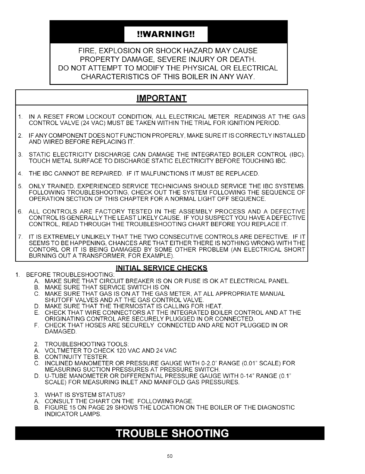
!!WARNING!!
FIRE, EXPLOSION OR SHOCK HAZARD MAY CAUSE
PROPERTY DAMAGE, SEVERE INJURY OR DEATH.
DO NOT ATTEMPT TO MODIFY THE PHYSICAL OR ELECTRICAL
CHARACTERISTICS OF THIS BOILER IN ANY WAY.
IMPORTANT
.
2.
3.
4.
5.
IN A RESET FROM LOCKOUT CONDITION, ALL ELECTRICAL METER READINGS AT THE GAS
CONTROL VALVE (24 VAC) MUST BE TAKEN WITHIN THE TRIAL FOR IGNITION PERIOD.
IFANY COMPONENT DOES NOT FUNCTION PROPERLY, MAKE SURE IT IS CORRECTLY INSTALLED
AND WIRED BEFORE REPLACING IT.
STATIC ELECTRICITY DISCHARGE CAN DAMAGE THE INTEGRATED BOILER CONTROL (IBC).
TOUCH METAL SURFACE TO DISCHARGE STATIC ELECTRICITY BEFORE TOUCHING IBC.
THE IBC CANNOT BE REPAIRED. IF IT MALFUNCTIONS IT MUST BE REPLACED.
ONLY TRAINED, EXPERIENCED SERVICE TECHNICIANS SHOULD SERVICE THE IBC SYSTEMS.
FOLLOWING TROUBLESHOOTING, CHECK OUT THE SYSTEM FOLLOWING THE SEQUENCE OF
OPERATION SECTION OF THIS CHAPTER FOR A NORMAL LIGHT OFF SEQUENCE.
ALL CONTROLS ARE FACTORY TESTED IN THE ASSEMBLY PROCESS AND A DEFECTIVE
CONTROL IS GENERALLY THE LEAST LIKELY CAUSE. IF YOU SUSPECT YOU HAVE A DEFECTIVE
CONTROL, READ THROUGH THE TROUBLESHOOTING CHART BEFORE YOU REPLACE IT.
IT IS EXTREMELY UNLIKELY THAT THE TWO CONSECUTIVE CONTROLS ARE DEFECTIVE. IF IT
SEEMS TO BE HAPPENING, CHANCES ARE THAT EITHER THERE IS NOTHING WRONG WITH THE
CONTORL OR IT IS BEING DAMAGED BY SOME OTHER PROBLEM (AN ELECTRICAL SHORT
BURNING OUT A TRANSFORMER, FOR EXAMPLE).
INITIAL SERVICE CHECKS
BEFORE TROUBLESHOOTING:
A. MAKE SURE THAT CIRCUIT BREAKER IS ON OR FUSE IS OKAT ELECTRICAL PANEL.
B. MAKE SURE THAT SERVICE SWITCH IS ON.
C. MAKE SURE THAT GAS IS ON AT THE GAS METER, AT ALL APPROPRIATE MANUAL
SHUTOFF VALVES AND AT THE GAS CONTROL VALVE.
D. MAKE SURE THAT THE THERMOSTAT IS CALLING FOR HEAT.
E. CHECK THAT WIRE CONNECTORS AT THE INTEGRATED BOILER CONTROL AND AT THE
ORIGINATING CONTROL ARE SECURELY PLUGGED IN OR CONNECTED.
F. CHECK THAT HOSES ARE SECURELY CONNECTED AND ARE NOT PLUGGED IN OR
DAMAGED.
2. TROUBLESHOOTING TOOLS:
A. VOLTMETER TO CHECK 120 VAC AND 24 VAC
B. CONTINUITY TESTER.
C. INCLINED MANOMETER OR PRESSURE GAUGE WITH 0-2.0" RANGE (0.01" SCALE) FOR
MEASURING SUCTION PRESSURES AT PRESSURE SWITCH.
D. U-TUBE MANOMETER OR DIFFERENTIAL PRESSURE GAUGE WITH 0-14" RANGE (0.1"
SCALE) FOR MEASURING INLET AND MANIFOLD GAS PRESSURES.
3. WHAT IS SYSTEM STATUS?
A. CONSULT THE CHART ON THE FOLLOWING PAGE.
B. FIGURE 15 ON PAGE 29 SHOWS THE LOCATION ON THE BOILER OF THE DIAGNOSTIC
INDICATOR LAMPS.
5O
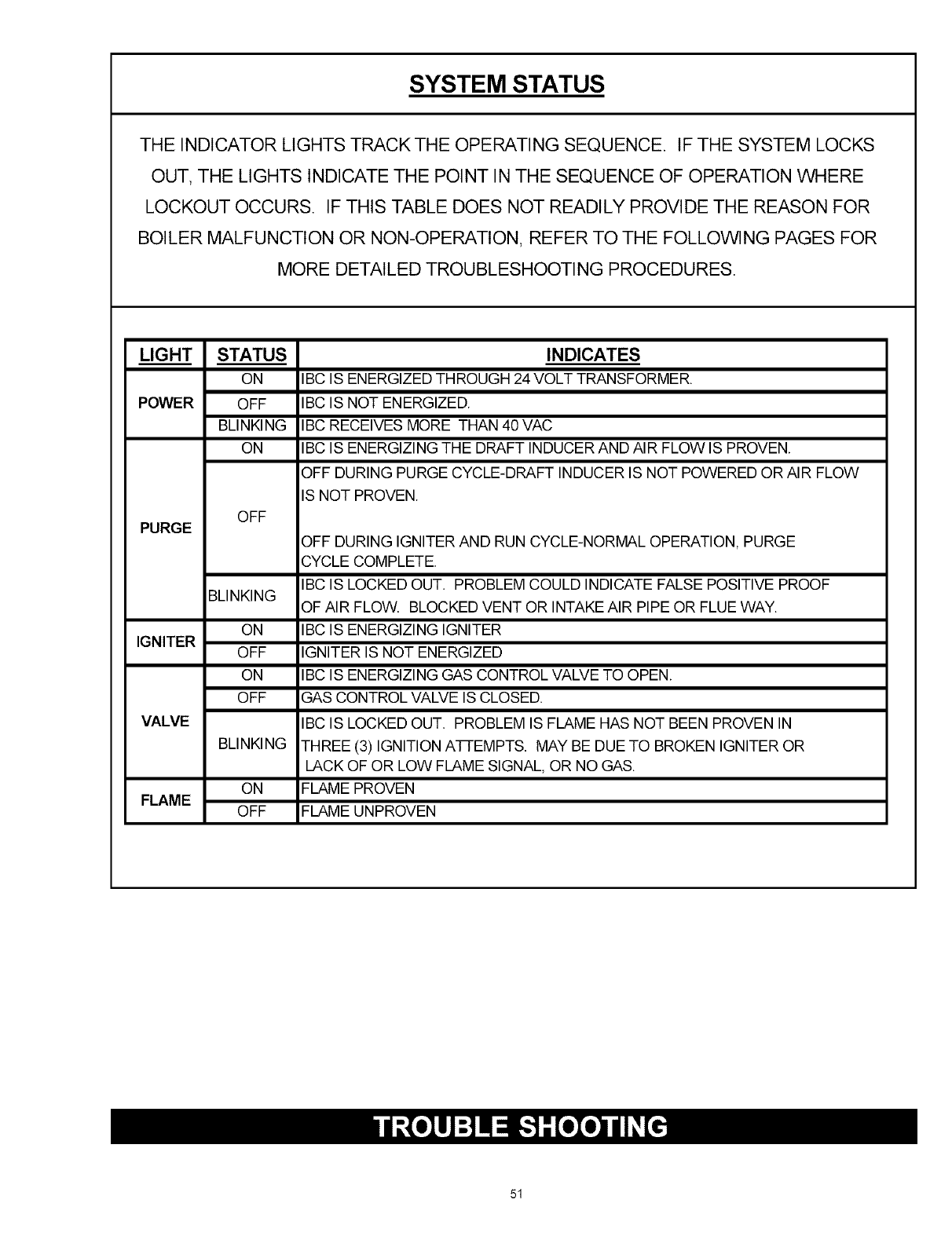
SYSTEM STATUS
THE INDICATOR LIGHTS TRACK THE OPERATING SEQUENCE. IF THE SYSTEM LOCKS
OUT, THE LIGHTS INDICATE THE POINT IN THE SEQUENCE OF OPERATION WHERE
LOCKOUT OCCURS. IF THIS TABLE DOES NOT READILY PROVIDE THE REASON FOR
BOILER MALFUNCTION OR NON-OPERATION, REFER TO THE FOLLOWING PAGES FOR
MORE DETAILED TROUBLESHOOTING PROCEDURES.
LIGHT
POWER
PURGE
IGNITER
VALVE
STATUS
ON
OFF
BLINKING
ON
OFF
BLINKING
ON
OFF
ON
OFF
BLINKING
ON
FLAME OFF
INDICATES
IBC IS ENERGIZED THROUGH 24 VOLT TRANSFORMER.
IBC IS NOT ENERGIZED.
IBC RECEIVES MORE THAN 40 VAC
IBC IS ENERGIZING THE DRAFT INDUCER AND AIR FLOW IS PROVEN.
OFF DURING PURGE CYCLE-DRAFT INDUCER IS NOT POWERED OR AIR FLOW
IS NOT PROVEN.
OFF DURING IGNITER AND RUN CYCLE-NORMAL OPERATION, PURGE
CYCLE COMPLETE.
IBC IS LOCKED OUT. PROBLEM COULD INDICATE FALSE POSITIVE PROOF
OF AIR FLOW. BLOCKED VENT OR INTAKE AIR PIPE OR FLUE WAY.
IBC IS ENERGIZING IGNITER
IGNITER IS NOT ENERGIZED
IBC IS ENERGIZING GAS CONTROL VALVE TO OPEN.
GAS CONTROL VALVE IS CLOSED.
IBC IS LOCKED OUT. PROBLEM IS FLAME HAS NOT BEEN PROVEN IN
THREE (3) IGNITION A-I-TEMPTS. MAY BE DUE TO BROKEN IGNITER OR
LACK OF OR LOW FLAME SIGNAL, OR NO GAS.
FLAME PROVEN
FLAME UNPROVEN
51
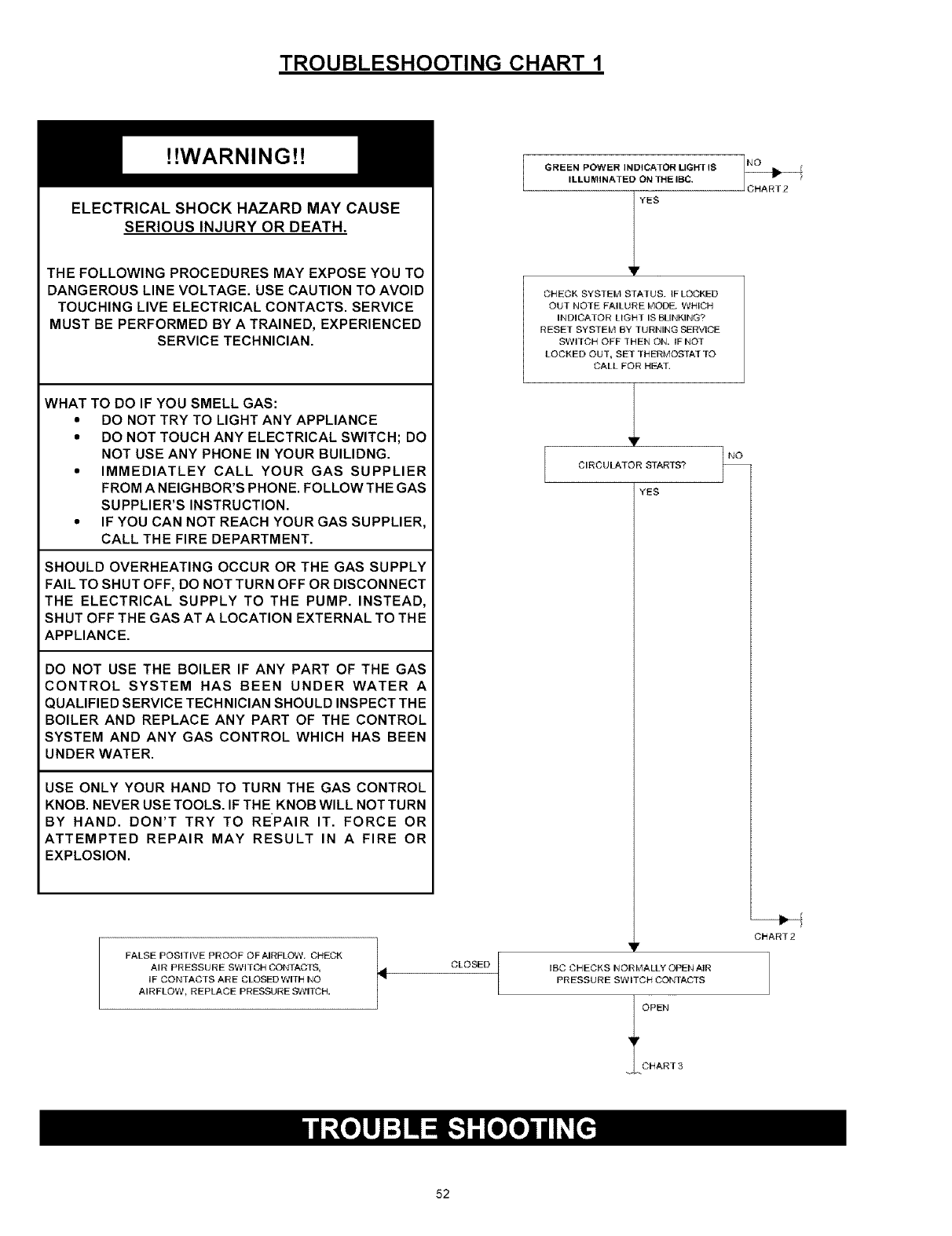
TROUBLESHOOTING CHART 1
!!WARNING!!
ELECTRICAL SHOCK HAZARD MAY CAUSE
SERIOUS INJURY OR DEATH.
THE FOLLOWING PROCEDURES MAY EXPOSE YOU TO
DANGEROUS LINE VOLTAGE. USE CAUTION TO AVOID
TOUCHING LIVE ELECTRICAL CONTACTS. SERVICE
MUST BE PERFORMED BY A TRAINED, EXPERIENCED
SERVICE TECHNICIAN.
WHAT TO DO IF YOU SMELL GAS:
•DO NOT TRY TO LIGHT ANY APPLIANCE
•DO NOT TOUCH ANY ELECTRICAL SWITCH; DO
NOT USE ANY PHONE IN YOUR BUILIDNG.
•IMMEDIATLEY CALL YOUR GAS SUPPLIER
FROM A NEIGHBOR'S PHONE. FOLLOW THE GAS
SUPPLIER'S INSTRUCTION.
"IF YOU CAN NOT REACH YOUR GAS SUPPLIER,
CALL THE FIRE DEPARTMENT.
SHOULD OVERHEATING OCCUR OR THE GAS SUPPLY
FAIL TO SHUT OFF, DO NOT TURN OFF OR DISCONNECT
THE ELECTRICAL SUPPLY TO THE PUMP. INSTEAD,
SHUT OFF THE GAS AT A LOCATION EXTERNAL TO THE
APPLIANCE.
DO NOT USE THE BOILER IF ANY PART OF THE GAS
CONTROL SYSTEM HAS BEEN UNDER WATER A
QUALIFIED SERVICE TECHNICIAN SHOULD INSPECT THE
BOILER AND REPLACE ANY PART OF THE CONTROL
SYSTEM AND ANY GAS CONTROL WHICH HAS BEEN
UNDER WATER.
USE ONLY YOUR HAND TO TURN THE GAS CONTROL
KNOB. NEVER USE TOOLS. IF THE KNOB WILL NOT TURN
BY HAND. DON'T TRY TO REPAIR IT. FORCE OR
ATTEMPTED REPAIR MAY RESULT IN A FIRE OR
EXPLOSION.
FALSE POSITIVE PROOF OFAIRFLOW. CHECK
AIR PRESSURE SWITCH CONTACTS,
IF CONTACTS ARE CLOSED WITH NO
AIRFLOW, REPLACE PRESSURE SWITCH, t CLOSED
GREEN POWER INDICATOR LIGHT IS
ILLUMINATED ON THE IBC,
YES
CHECK SYSTEM STATUS. IF LOCKED
OUT NOTE FAILURE MODE. WHICH
INDICATOR LIGHT IS BLINKING?
RESET SYSTEM BY TURNING SERVICE
SWITCH OFF THEN ON, IF NOT
LOCKED OUT, SET THERMOSTAT TO
CALL FOR HEAT.
NO
CIRCULATOR STARTS?
YES
NO
CHART2
v
IBC CHECKS NORMALLY OPEN AIR
PRESSURE SWITCH CONTACTS
OPER
CHART3
52
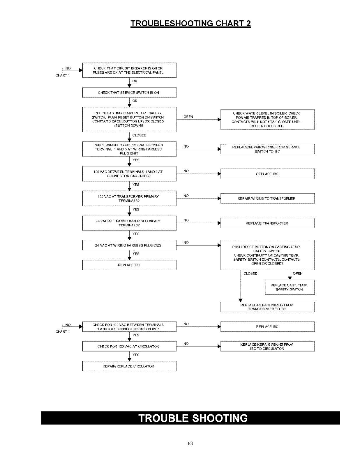
TROUBLESHOOTING CHART 2
cHA CHECK THAT CIRCUIT BREAKER IS ON OR
FUSES ARE OK ATTHE ELECTRICAL PANEL
OK
CHECK THAT SERVICE SWITCH IS ON
OK
CHECK CASTING TEMPERATURE SAFETY
SWITCH. PUSH RESET BUTTON ON SWITCH.
CONTACTS OPEN (BUTTON UP) OR CLOSED
(BUTTON DOWN)?
CLOSED
CHECK WIRING TO IBC 120 VAC BE'C_NEEN
TERMINAL 1 AND 3ATWIRINGRARNESS
PLUG CN7?
YES
120VAC BETWEENTERMINALS 1AND 3 AT
CONNECTOR CN3 ON tBC?
YES
120 VAC AT TRANSFORMER PRIMARY
TERMINALS?
YES
24 VAC AT TRANSFORMER SECONDARY
TERMIRALS?
YES
24 VAC AT WIRING HARNESS PLUG CN2?
YES
REPLACE IBC
OPEN
NO
NO
NO
NO
NO
CHECK WATER LEVEL IN BOILER. CHECK
FOR AIR TRAPPED IN TOP OF BOILER
CONTACTS WILL NOT STAY CLOSED UNTIL
BOILER COOLS OFF.
REPLACE/RE PAl RW IRI NG FROM S ERVICE
SWITCH TO IBC
REELACEIBC
REPAIR WIRING TO TRANSFORMER
REPLACE TRANSFORMER
PUSH RESET BUTTON ON CASTING TEMP,
SAFETY SWITCH.
CHECK CONTINUITY OF CASTINGTEMP.
SAFETY SWITCH COBITACTS, COi'_ITACTS
OPEN OR CLOSED?
V CLOSED '4F OEEN
REPLACE CAST, TEMF,
SAFETY SWITCH,
REPLACE/REPAIR "_ IRING FROM
TRANSFORMER TO IBC
CHART 1
CHECK FOR 120 VAC BE"PA EEN TERMIRALS
1 AND 3 AT CONNECTOR CN5 ON IBC?
YES
CHECK FOR 120 VAC AT CIRCULATOR
YES
REFAtPJ REPLACE CIRCULATOR
NO
NO ,I
REPLACE IBC
REPLACE/REPAIR WIRING FROM
IBC TO CIRCULATOR
53
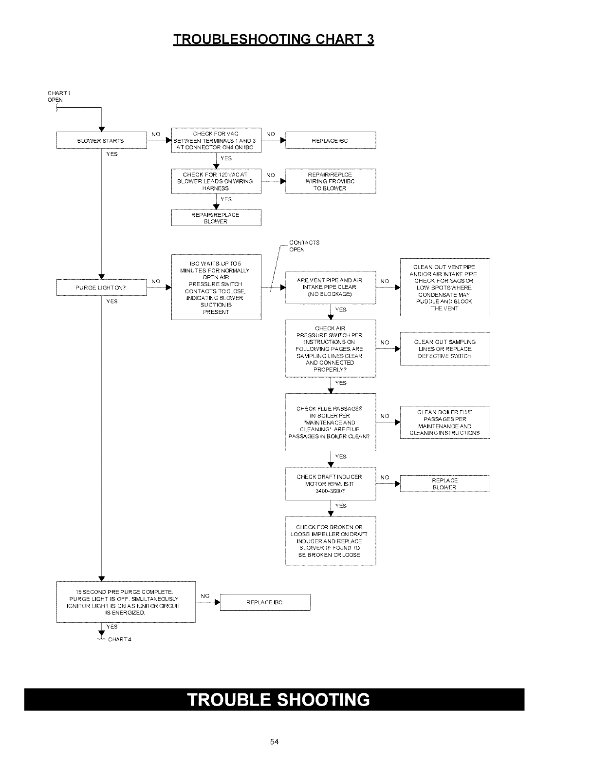
TROUBLESHOOTING CHART 3
CHART I
OPEN ,l
BLOWER STARTS
YES
NO
15 SECOND PRE PURGE COMPLETE
PURGE LIGHT IS OFF SIk4ULTANEOUSL"t
IGNITOR LIGHT tS ON AS IGNITOR CIRCUIT
tS ENERGIZED.
YES
CHECK FOR 120VACAT NO I
BLOWER LEA D S ON I/IIIRING
HARNESS
YES
R EPAIR/REPLACESLOWER
IBC WAITS UPTO5
MINUTES FOR NOR_,'IALL"t
OPEN AIR
PRESSURE SWITCH
CON TACTS TO CLOSE,
INDICATING BLOW ER
SUCTION IS
PRESENT
REPLACE tBC
REPAIR/REPLCE
WIRING FR OMIIBC
TO BLOWER
CONTACTS
OPEN
ARE VENT PIPE AND AIR
INTAKE PIPE CLEAR
(NO BLOCKAGE)
1 4,
CHECK AIR
PRESSURE SWITCH PER
INSTRUCTIONS ON
FOLLOWING PA GES.ARE
SA _'IPLtN G LINES CL_f_R
AND CONNECTED
PROPERLY'?
YES
CHECK FLUE PASSAGES
IN BOILER PER
"k_INTENA CE AND
CLEANING" ARE FLUE
PASSAGES IN BOILER CLSAN?
YES
CHECK DRAFTINDUCER t_
MOTOR RPM. BIT
3400-3600?
YES
CHECK FOR BROKEN OR
LOOSE IMPELLER ON DRAFT
INDUCER AND REPLACE
BLOWER IF FOUND TO
BE BROKEN OR LOOSE
REPLACE IBC
CLEAN OUT VENT PIPE
AND/OR AIR INTAKE PIPE
CHECK FOR SAGS OR
LOW SPOTSWHERE
CONDENSATE _'IAY
PUDDLEAND BLOCK
THEVENT
CLEAN OUT SAMPLING
LINES OR REPLACE
DEFECTIVE SWITCH
CLEAN BOILER FLUE
PASSAGES PER
MAINTENANCE AND
CLEANING INSTRUCTIONS
REPLACE
BLOWER
54
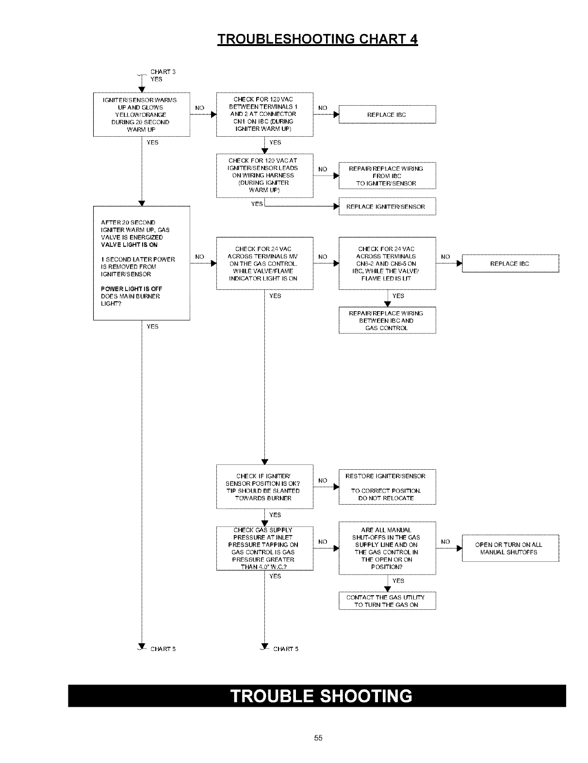
TROUBLESHOOTING CHART 4
CI_RT 3
"_" YES
IGNITER/SENSOR WARMS
UP AND GLOWS
Y ELLOW/ORA HGE
DURING 20 SECOND
WARM UP
YES
AFTER 20 SECOND
IGNITER WARM UP, GAS
VALVE IS ENERGIZED
VALVE LIGHT IS ON
1SECOND LATER POWER
IS REMOVED FROM
IGNITERtS ENSOR
POWER LIGHT IS OFF
DOES MAIN BURNER
LIGHT?
YES
CH& RT 5
CHECK FOR 120VAC
BE_A_E EN T E RMli',IALS 1
AND 2 AT CONNECTOR
CN1 ON tBC (DURING
IGNITER WARM UP)
I_YES
CHECK FOR 12C*VAC AT
IGNITER/SENSOR LEADS
ON WIRING HARNESS
(DURING IGNITER
WARM UP)
YESI
REPLACE IBC ]
REPAIPJ REP LACE WIRING
FROM IBC
TO IGNITE _ SENSOR
REPLACE IGNITEPJ SENSOR
CHE CK FOR 24 VAC
ACROSS TERMINALS MV
OH THE GAS CONTROL.
WHILE VALVE/FLAME
INDICATOR LIGHT IS ON
YES
CHECK FOR 24VAC
ACROSS TERMINALS
CN8-2 AND CN6-5 ON
IBC, WHILE THE VALVE/
FLAME LED IS LIT
yYES
REPAIR/REPLACE WIRING
BETWEEN IBC AND
GAS CONTROL
CHECK IF IGNITER/
SENSOR POSITION IS OK?
TIP SHOULD BE SLANTED
TOWARDS BURNER
YES
CHECK GAS SUPPLY
PRESSURE AT INLET
PRESSURE TAPPING ON
GAS CONTROL IS GAS
PRESSURE GREATER
THAN 4,0" W,C.?
YES
RESTORE IGNITER/SENSOR
TO CORRECT POSITION.
DO NOT RELOCATE
CHART 5
N_ ARE ALL MANUAL
SHUT-OFFS IN THE GAS
SUPPLY LINE AND ON
THE GAS CONTROL IN
THE OPEN OR ON
POSITION?
YES
CONTACT THE GAS UTILITY
TO TURN THE GAS ON
REPLACE IBC
OPEN OR TURN ON ALL
MANUAL SHUTOFFS
55
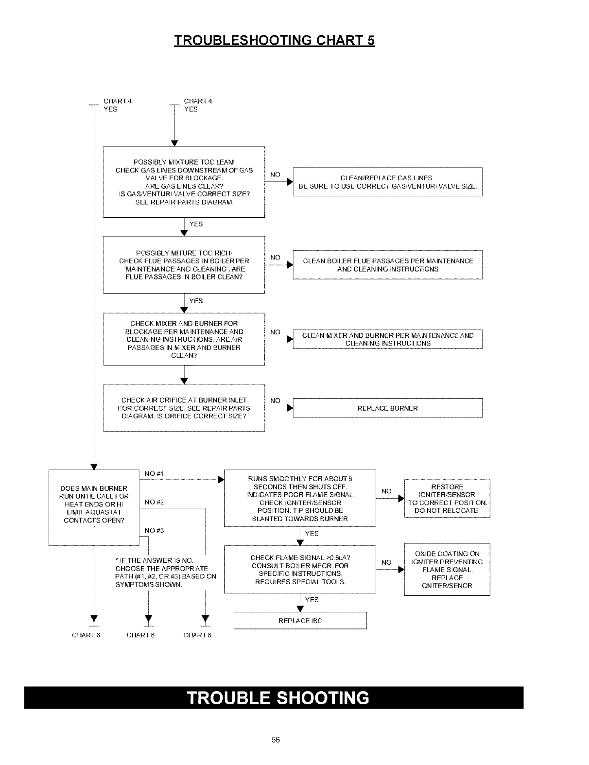
TROUBLESHOOTING CHART 5
CHART4
YES
CHART4
YES
POSSIBLY MIXTURE TOO LEAN!
CHECK GAS LINES DOWNSTREAM OF GAS
VALVE FOR BLOCKAGE.
ARE GAS LINES CLEAR?
IS GAS/VENTURI VALVE CORRECT SIZE?
SEE REPAIR PARTS DIAGRAM,
_r YES
POSSIBLY MITURE TOO RICH!
CHECK FLUE PASSAGES IN BOILER PER
"MA INTENANCE AND CLEANING", ARE
FLUE PASSAGES iN BOILER CLEAN?
_IF YES
CHECK MIXER AND BURNER FOR
BLOCKAGE PER MAINTENANCE AND
CLEANING INSTRUCTIONS AREAIR
PASSAGES IN MIXER AND BURNER
CLEAN?
CHECK AIR ORIFICE AT BURNER INLET
FOR CORRECT SIZE, SEE REPAIR PARTS
DIAGRAM IS ORIFICE CORRECT SIZE?
CLEAN/REPLACE GAS LINES.
BE SURE TO USE CORRECT GAS/VENTURI VALVE SIZE.
CLEAN BOILER FLUE PASSAGES PER MAINTENANCE
AND CLEANING INSTRUCTIONS
CLEAN MIXER AND BURNER PER iVIAINTENANCE AND
CLEANING INSTRUCTIONS
REPLACE BURNER
DOES MAiN BURNER
RUN UNTIL CALL FOR
HEAT ENDS OR HI
LIM IT AQUASTAT
CONTACTS OPEN?
CHART6
NO#1
NO #2
NO ,#,3
q
*IF THE ANSWER IS NO,
CHOOSE THE APPROPRIATE
PATH (#1, #2, OR #3) BASED ON
SYMPTOMS SHOWN,
CHART 6 CHART 6
RUNS SMOOTHLY FOR ABOUT 5
SECONDS THEN SHUTS OFF,
INDICATES POOR FLAME SIGNAL,
CHECK IGN JTER/SENSOR
POSITION. TIP SHOULD BE
SLANTED TOWARDS BURNER
IFYES
CHECK FLAME SIGNAL >O,6uA?
CONSULT BOILER MFGR. FOR
SPECIFIC INSTRUCTIONS.
REQUIRES SPECIAL TOOLS.
YES
REPLACE IBC J
RESTORE
IGNITER/SENSOR
TO CORRECT POSITION,
DO NOT RELOCATE
OXIDE COATING ON
IGNITER PREVENTING
FLAME SIGNAL
REPLACE
IGNITER/SENOR
56
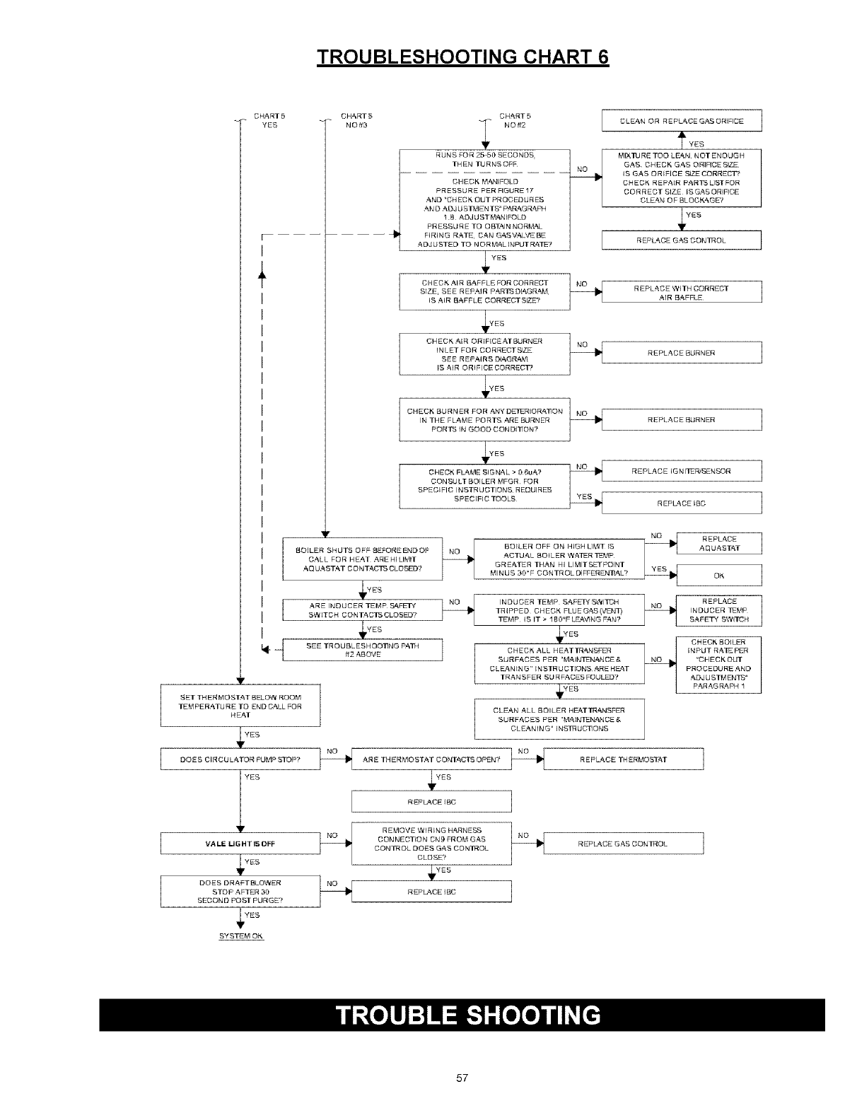
TROUBLESHOOTING CHART 6
[
CHART5
YES
[
L
+
CHART
NO#3
SETTHERMOSTATBELOWROOM
TEMPERATURE TO END _ALL FOR
HEAT
YES
CHART 5
_ NO#2
RUNS FOR 25 50 SECONDS _
THEN TURNS OFF
CHECK MANIFOLD
PRESSURE PER FIGURE 17
AND "CHECK OUT PROCEDURES
AN [3 ADJ U STME N TS" PARAGRAPH
1 B ADJUST_,_NIFOLO
PRESSURE TO OBE_IN NOR_,_t_L
FIRING RATE¸ CAN GASVALVE BE
A OJ USTE D TO N OR _IAL INPUT RAIE?
YES
CH ECK A_R BAFFLE FOR CORRECT _
SIZE¸ SEE REPAIR PARIS DIAGRAk_I
IS AIR BAFFLE CORRECTSI_?
CHECK AIR ORIFICEATSURNER _
INLET FOR CORRECTSI,_
SEE REPAIRS DIAGRAk&
IS AIR ORIFICE CORRECT_
/
CHECN BURNER FOR ANYO_R_OR_A_ON _
IN THE FLA_E PORTB_ _ARE SURNER
PORTS IN GOOO CONDI1]OR?
CHECK FLAME SIGNAL > _ 6uA? N_2_
CON SU LT BOI LER MFGR FO R
SPECIFIC INSTRUCTIONS¸ REQUIRES
SPECIFIC I'OOLS
'F
BOILER SHUTS OFF BEFOREENDOF I NO
CALL FOR HEAT .ARE HI LIMIT
AQ UAETAT CONTACTS CLOSED?
YES
ARE INDUCER TEMP _FE3-_ r I I_u ii_
SWITCH CONTACTS CLOSED?
__)'ES
SEE TROUBLESHOO]]NG P_TH L
J
#2 '_B OVE
BO_LER OFF ON HIGH LIkSIT _S
ACTU'_L BOILER WATER TEk_P
GREATER THAN HI LIMITSETPOINT
k,ll N U S 30 _F CON TR OL DIFFER EN_AL?
INDUCER TEMP SAFEIS"SWITCH
TR I PP ED CH ECK FLU E GAS (VENT)
TEMP IS IT > 1B0_F LE_.VING FAN?
_,¥ES
CHECK ALL HEATTRANEFER
SURFACES PER "_,_AIN_I_NANCE £_
CLEANER G" INSTR U CTIONS ARE HE_,T
TRANSFER S U R FACES FOULED','
4,"EB
CLEAN ALL BOILER HEATTRANSFER
SURFACES PER "MAINTLNANCE @,
CLEANING" INSTR UC_ ORS
ODE S CIR CU L _TOR PUMP S]I%}P? _ ARE TH ER _,,_OS_'_,T CONT_',CTS OPEN? _
ES 4 ES
R EPL'_.CE IBC 1
_ _ REMOVE WIRING HARNESS _
CONWECTION ON9 FR O_._ GAS
VALE LIGHT I_ OFF CON1N OL DOES GAS CON/NOL
"€'ES CLOSE?
__YES
DOES DRAFT BLOWER _ 7
STOP AFTER 30 REPL_.CE IBC
SECOND POST PURGE?
YES
S'f STE_°I OK
CLEAN OR REPLACE GASORIFICE ]
rYES
_¢_JRE TOO LE_N NOT ENOUGH
GAS CHECK GAS ORIFICESIZE
IS GAS ORIFICE SIZE CORRECT?
CHECK REPAIR PARTSLISTFOR
CORRECT ShEE IS GAS ORIFICE
CLEAN OF BLOCK_,GE?
REPLACE GAS CONTROL J
REPLACE WITH CORRECT ]
_IR S_FFLE_
REPLACE BURNER 1
REPLACE BURNER 1
REPLACE IG RITER/SENSOR 1
R EPLZ_CE IBO ]
N_ REPLACE
A_ U_S_T 1
oK ]
_ REPLACE 1
INDUCER TR_P
S_ETY SWITCH
CHECK BOILER
INPUT RATE PER
"CHECKOUT
PROCEDURE AND
ADJ U STM EATS"
PARAGRARH 1
R EP L,'_.CE TH ER _._OSEAT ]
R EPLa, CE GAS CONTROL ]
57
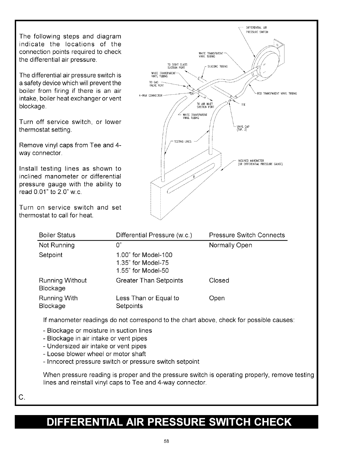
The following steps and diagram
indicate the locations of the
connection points required to check
the differential air pressure.
The differential air pressure switch is
a safety device which will prevent the
boiler from firing if there is an air
intake, boiler heat exchanger or vent
blockage.
Turn off service switch, or lower
thermostat setting.
Remove vinyl caps from Tee and 4-
way connector.
Install testing lines as shown to
inclined manometer or differential
pressure gauge with the ability to
read 0.01" to 2.0" w.c.
Turn on service switch and set
thermostat to call for heat.
TO SIGHT GLASS
SUCTION PORT
WRITE TRANSPANZNT
VINYL TUBING _
TO GAS .....
VALVEVSRT ......... _
4-WAY CONNER[ON
DIFFERENTIALAIR
\ PRESSURE SWITCH
\
\
\
\
\
WHITE TRANSPARENT_
VINYL TUBING
\\
SILICONE TUBING
/
/
f --
/
/TO AIR INLET
SUCTION PORT
WHITE TRANSPARENT
VHYZ TUBING
i_ _ TESTING LINES
/
/
/
TRANSPARENT VINYL TUBN6
_ VINYL CAP
(EYP. 2)
INCLINED _AROMETER
J (OR DIFFERENTIALPRESSURE GAUGE)
C,
Boiler Status
Not Running
Setpoint
Running Without
Blockage
Running With
Blockage
Differential Pressure (w.c.)
0 _
1.00" for Model-100
1.35" for Model-75
1.55" for Model-50
Greater Than Setpoints
Pressure Switch Connects
Normally Open
Closed
Less Than or Equal to Open
Setpoints
If manometer readings do not correspond to the chart above, check for possible causes:
- Blockage or moisture in suction lines
- Blockage in air intake or vent pipes
- Undersized air intake or vent pipes
- Loose blower wheel or motor shaft
- Inncorect pressure switch or pressure switch setpoint
When pressure reading is proper and the pressure switch is operating properly, remove testing
lines and reinstall vinyl caps to Tee and 4-way connector.
58
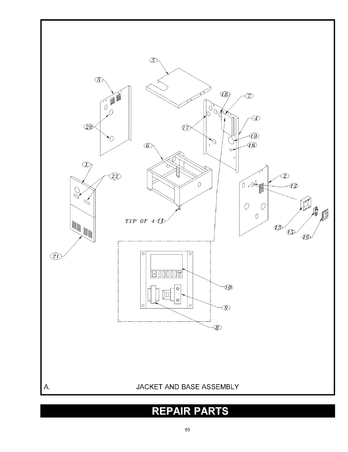
TYP OF 4 _>/
....................................... > ...... __J
0
//
J
//
A. JACKET AND BASE ASSEMBLY
59
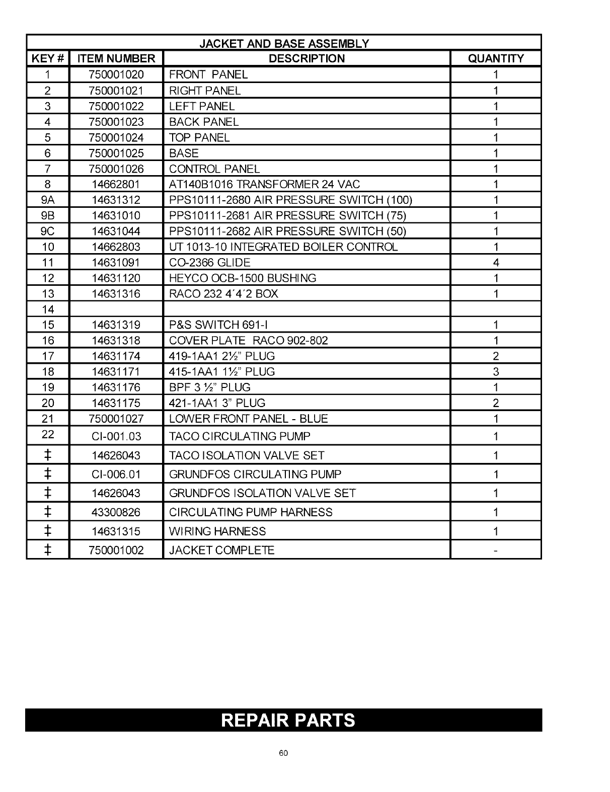
KEY #
1
2
3
4
5
6
7
8
9A
9B
9C
10
11
12
13
14
15
16
17
18
19
20
21
22
ITEM NUMBER
750001020
750001021
750001022
750001023
750001024
750001025
750001026
14662801
14631312
14631010
14631044
14662803
14631091
14631120
14631316
JACKET AND BASE ASSEMBLY
DESCRIPTION
FRONT PANEL
RIGHT PANEL
LEFT PANEL
BACK PANEL
TOP PANEL
BASE
CONTROL PANEL
AT140B1016 TRANSFORMER 24 VAC
PPS10111-2680 AIR PRESSURE SWITCH (100)
PPS10111-2681 AIR PRESSURE SWITCH (75)
PPS10111-2682 AIR PRESSURE SWITCH (50)
UT 1013-10 INTEGRATED BOILER CONTROL
C0_2366 GLIDE
HEYCO OCB-1500 BUSHING
RACO 232 4"4"2 BOX
QUANTITY
1
1
1
1
1
1
1
1
1
1
1
1
4
1
1
14631319 P&S SWITCH 691-1 1
14631318 COVER PLATE RACO 902-802 1
14631174 419-1AA1 2½" PLUG 2
14631171 415-1AA1 1½" PLUG 3
14631176 BPF 3 ½" PLUG 1
14631175 421-1AA1 3" PLUG 2
750001027 LOWER FRONT PANEL - BLUE 1
CI-001.03 TACO CIRCULATING PUMP 1
14626043 TACO ISOLATION VALVE SET 1
CI-006.01 GRUNDFOS CIRCULATING PUMP 1
14626043 GRUNDFOS ISOLATION VALVE SET 1
43300826 CIRCULATING PUMP HARNESS 1
14631315 WIRING HARNESS 1
750001002 JACKET COMPLETE
6O
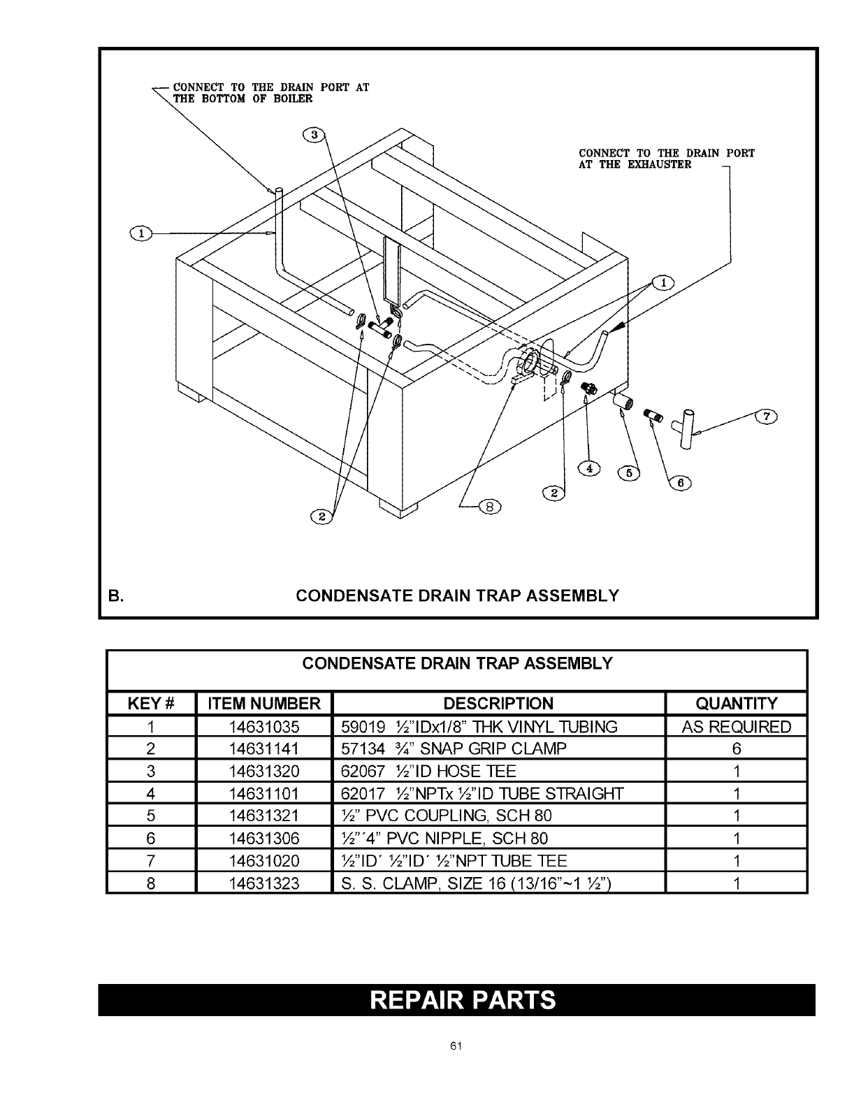
TO THE DRAIN PORT AT
THE BOTTOM OF BOILER
CONNECT TO THE DRAIN PORT
AT THE EXHAUSTER
O
B= CONDENSATE DRAIN TRAP ASSEMBLY
KEY #
1
2
3
4
5
6
7
8
CONDENSATE DRAIN TRAP ASSEMBLY
ITEM NUMBER
14631035
14631141
14631320
14631101
14631321
14631306
14631020
14631323
DESCRIPTION
59019 ½"lDxl/8" THK VINYL TUBING
57134 ¾" SNAP GRIP CLAMP
62067 ½"ID HOSE TEE
62017 ½"NPTx ½"ID TUBE STRAIGHT
½" PVC COUPLING, SCH 80
½"'4" PVC NIPPLE, SCH 80
½"ID" ½"ID" ½"NPTTUBE TEE
S. S. CLAMP, SIZE 16 (13/16"~1 ½")
QUANTITY
AS REQUIRED
6
1
1
1
1
1
1
61
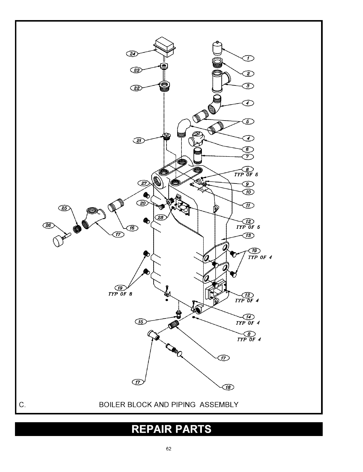
!
I
TYP OF 5
TYP OF 8
TYP OF 5
TYP OF d
TYP OF 4
TYP OF 4
C, BOILER BLOCK AND PIPING ASSEMBLY
62
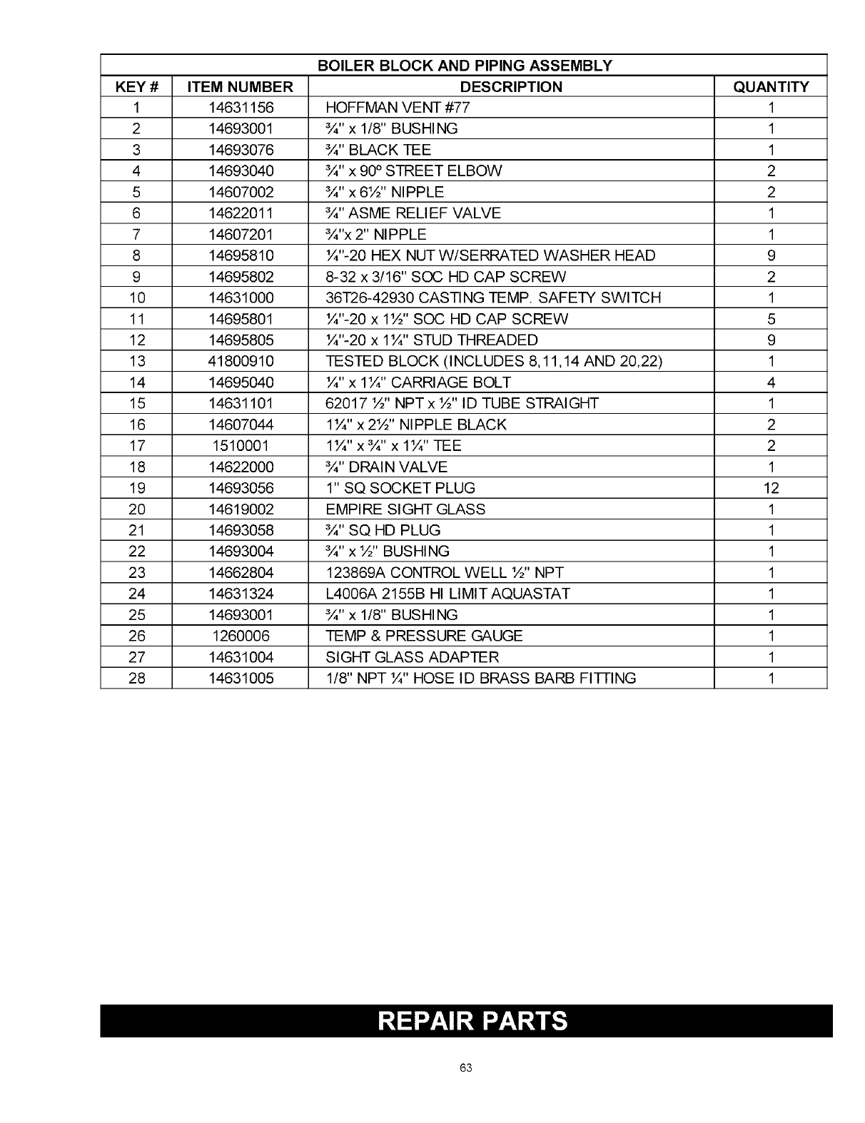
BOILER BLOCK AND PIPING ASSEMBLY
KEY # ITEM NUMBER DESCRIPTION QUANTITY
1 14631156 HOFFMAN VENT #77 1
2 14693001 ¾"x 1/8" BUSHING 1
3 14693076 ¾" BLACK TEE 1
4 14693040 ¾" x 90° STREET ELBOW 2
5 14607002 ¾" x 6½" NIPPLE 2
6 14622011 ¾" ASME RELIEF VALVE 1
7 14607201 ¾"x 2" NIPPLE 1
8 14695810 ¼"-20 HEX NUT W/SERRATED WASHER HEAD 9
9 14695802 8-32 x 3/16" SOC HD CAP SCREW 2
10 14631000 36T26-42930 CASTING TEMP. SAFETY SWITCH 1
11 14695801 ¼"-20 x 1½" SOC HD CAP SCREW 5
12 14695805 ¼"-20 x 1¼" STUD THREADED 9
13 41800910 TESTED BLOCK (INCLUDES 8,11,14 AND 20,22) 1
14 14695040 ¼"x 1¼" CARRIAGE BOLT 4
15 14631101 62017 ½" NPT x ½" ID TUBE STRAIGHT 1
16 14607044 1¼" x2½" NIPPLE BLACK 2
17 1510001 1¼" x¾"x 1¼" TEE 2
18 14622000 ¾" DRAIN VALVE 1
19 14693056 1" SQ SOCKET PLUG 12
20 14619002 EMPI RE SIGHT GLASS 1
21 14693058 ¾" SQ HD PLUG 1
22 14693004 ¾" x ½" BUSHING 1
23 14662804 123869A CONTROL WELL ½" NPT 1
24 14631324 L4006A 2155B HI LIMIT AQUASTAT 1
25 14693001 ¾"x 1/8" BUSHING 1
26 1260006 TEMP & PRESSURE GAUGE 1
27 14631004 SIGHT GLASS ADAPTER 1
28 14631005 1/8" NPT ¼" HOSE ID BRASS BARB FI-FFING 1
63
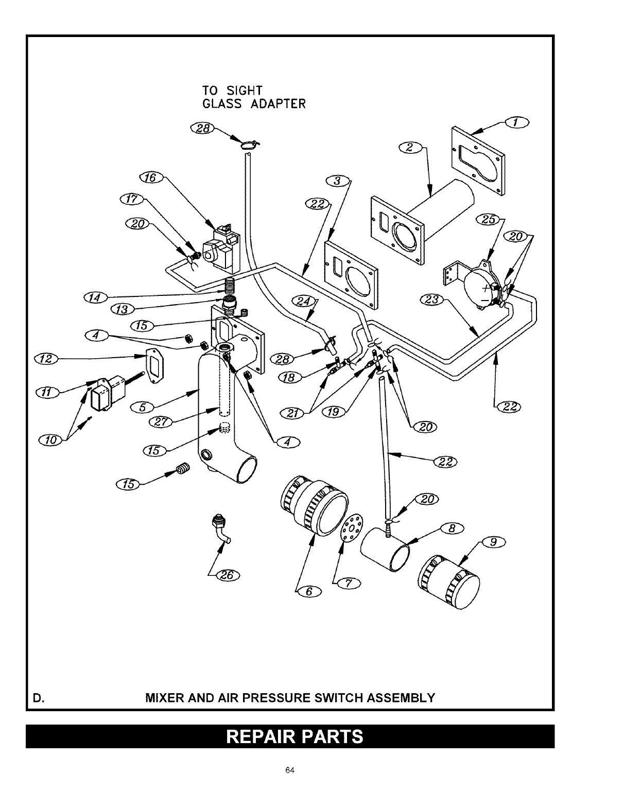
TO SIGHT
GLASS ADAPTER
D, MIXER AND AIR PRESSURE SWITCH ASSEMBLY
84
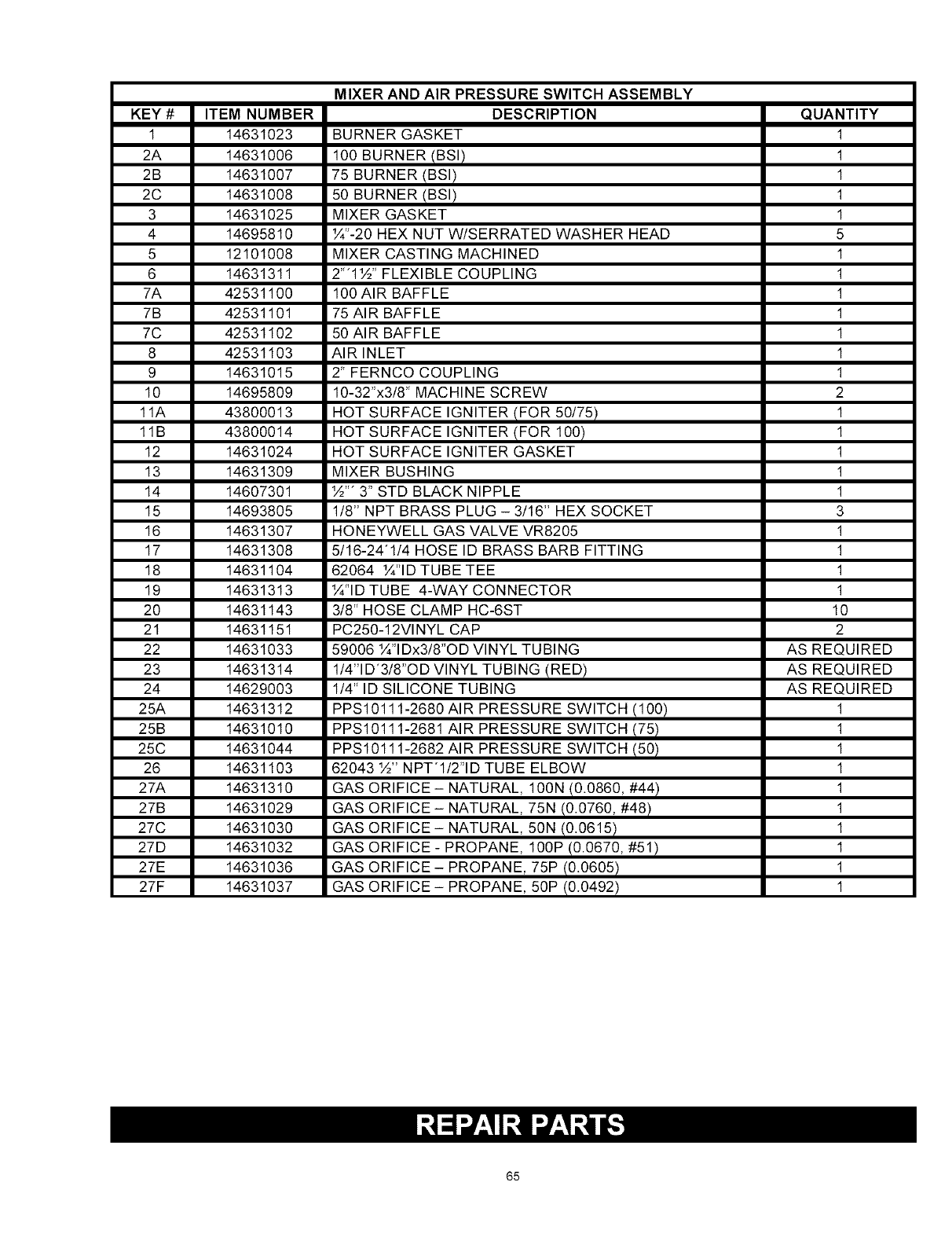
KEY #
1
2A
2B
2C
3
4
5
6
7A
7B
7C
8
9
10
11A
11B
12
13
14
15
16
17
18
19
2O
21
22
23
24
25A
25B
25C
26
27A
27B
27C
27D
27E
27F
ITEM NUMBER
14631023
14631006
14631007
14631008
14631025
14695810
12101008
14631311
42531100
42531101
42531102
42531103
14631015
14695809
43800013
43800014
14631024
14631309
14607301
14693805
14631307
14631308
14631104
14631313
14631143
14631151
14631033
14631314
14629003
14631312
14631010
14631044
14631103
14631310
14631029
14631030
14631032
14631036
14631037
MIXER AND AIR PRESSURE SWITCH ASSEMBLY
DESCRIPTION
BURNER GASKET
100 BURNER IBSI!
75 BURNER !BSI)
50 BURNER IBSI)
MIXER GASKET
¼"-20 HEX NUT W/SERRATED WASHER HEAD
MIXER CASTING MACHINED
2'"1½" FLEXIBLE COUPLING
100 AIR BAFFLE
75 AIR BAFFLE
50 AIR BAFFLE
AIR INLET
2" FERNCO COUPLING
10-32"x3/8" MACHINE SCREW
HOT SURFACE IGNITER IFOR 50/75)
HOT SURFACE IGNITER !FOR 100)
HOT SURFACE IGNITER GASKET
MIXER BUSHING
½"" 3" STD BLACK NIPPLE
1/8" NPT BRASS PLUG - 3/16" HEX SOCKET
HONEYWELL GAS VALVE VR8205
5/16-24"1/4 HOSE ID BRASS BARB FITTING
62064 ¼"ID TUBE TEE
¼"ID TUBE 4-WAY CONNECTOR
3/8" HOSE CLAMP HC-6ST
PC250-12Vl NYL CAP
59006 ¼"IDx3/8"OD VINYL TUBING
1/4"lg'3/8"og VINYL TUBING IRED)
1/4" ID SILICONE TUBING
PPS10111-2680 AIR PRESSURE SWITCH !100)
PPS10111-2681 AIR PRESSURE SWITCH !751
PPS10111-2682 AIR PRESSURE SWITCH 150)
62043 ½" NPT'I/2"ID TUBE ELBOW
GAS ORIFICE- NATURAL, 100N !0.0860, #44)
GAS ORIFICE - NATURAL, 75N I0.0760, #48)
GAS ORIFICE- NATURAL, 50N I0.0615)
GAS ORIFICE - PROPANE, 100P !0.0670, #51)
GAS ORIFICE - PROPANE, 75P I0.0605)
GAS ORIFICE - PROPANE, 50P (0.0492)
QUANTITY
1
1
1
1
1
5
1
1
1
1
1
1
1
2
1
1
1
1
1
3
1
1
1
1
10
2
AS REQUIRED
AS REQUIRED
AS REQUIRED
1
1
1
1
1
1
1
1
1
1
65
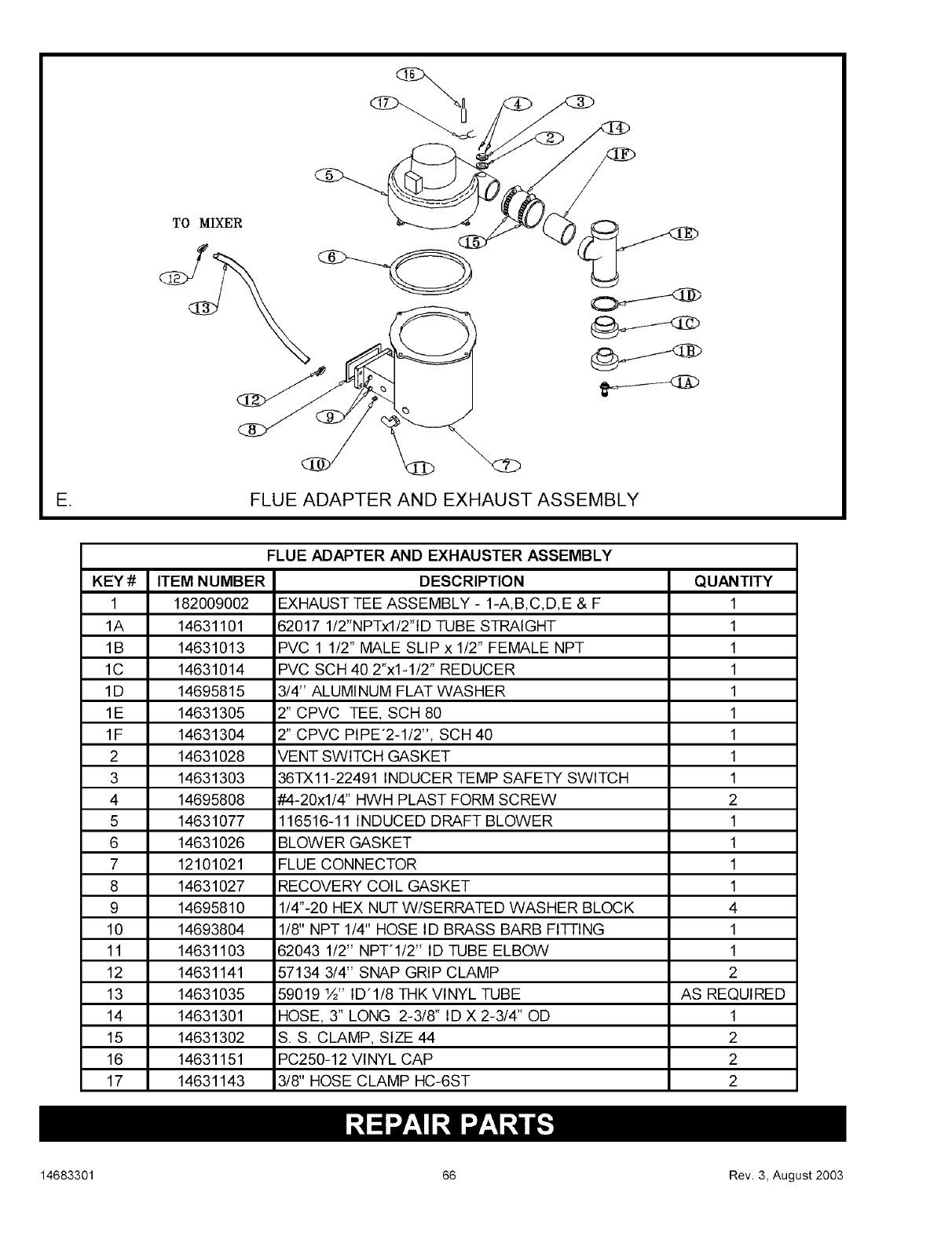
TO MIXER
E, FLUE ADAPTER AND EXHAUST ASSEMBLY
FLUE ADAPTER AND EXHAUSTER ASSEMBLY
KEY# ITEM NUMBER DESCRIPTION QUANTITY
1 182009002 EXHAUST TEE ASSEMBLY - 1-A,B,C,D,E & F 1
1A 14631101 82017 1/2"NPTxl/2"ID TUBE STRAIGHT 1
1B 14631013 PVC 1 1/2" MALE SLIP x 1/2" FEMALE NPT 1
1C 14631014 PVC SCH 40 2"x1-1/2" REDUCER 1
1D 14695815 3/4" ALUMINUM FLAT WASHER 1
1E 14631305 2" CPVC TEE, SCH 80 1
1F 14631304 2" CPVC PIPE'2-1/2", SCH 40 1
2 14631028 VENT SWITCH GASKET 1
3 14631303 36TXll-22491 INDUCER TEMP SAFETY SWITCH 1
4 14695808 #-4-20xl/4" HWH PLAST FORM SCREW 2
5 14631077 116516-11 INDUCED DRAFT BLOWER 1
6 14631026 BLOWER GASKET 1
7 12101021 FLUE CONNECTOR 1
8 14631027 RECOVERY COIL GASKET 1
9 14695810 1/4"-20 HEX NUT W/SERRATED WASHER BLOCK 4
10 14693804 1/8" NPT 1/4" HOSE ID BRASS BARB FI-FRNG 1
11 14631103 62043 1/2" NPT'I/2" ID TUBE ELBOW 1
12 14631141 57134 3/4" SNAP GRIP CLAMP 2
13 14631035 59019 ½" ID'1/8 THK VINYL TUBE AS REQUIRED
14 14631301 HOSE, 3" LONG 2-3/8" ID X 2-3/4" OD 1
15 14631302 S.S. CLAMP, SIZE 44 2
16 14631151 PC250-12 VINYL CAP 2
17 14631143 3/8" HOSE CLAMP HC-6ST 2
14683301 66 Rev. 3, August 2003
