Dalian Golden Hualu Digital Technology WF4101 WIFI Module User Manual
Dalian Golden Hualu Digital Technology Co.,Ltd. WIFI Module
UserManual.wiki
>
Dalian Golden Hualu Digital Technology
>
WF4101 User Manual
User manual
Navigation menu
Upload a User Manual
Namespaces
Wiki Guide
HTML
PDF
Info
Views
User Manual
Discussion / Help
Navigation
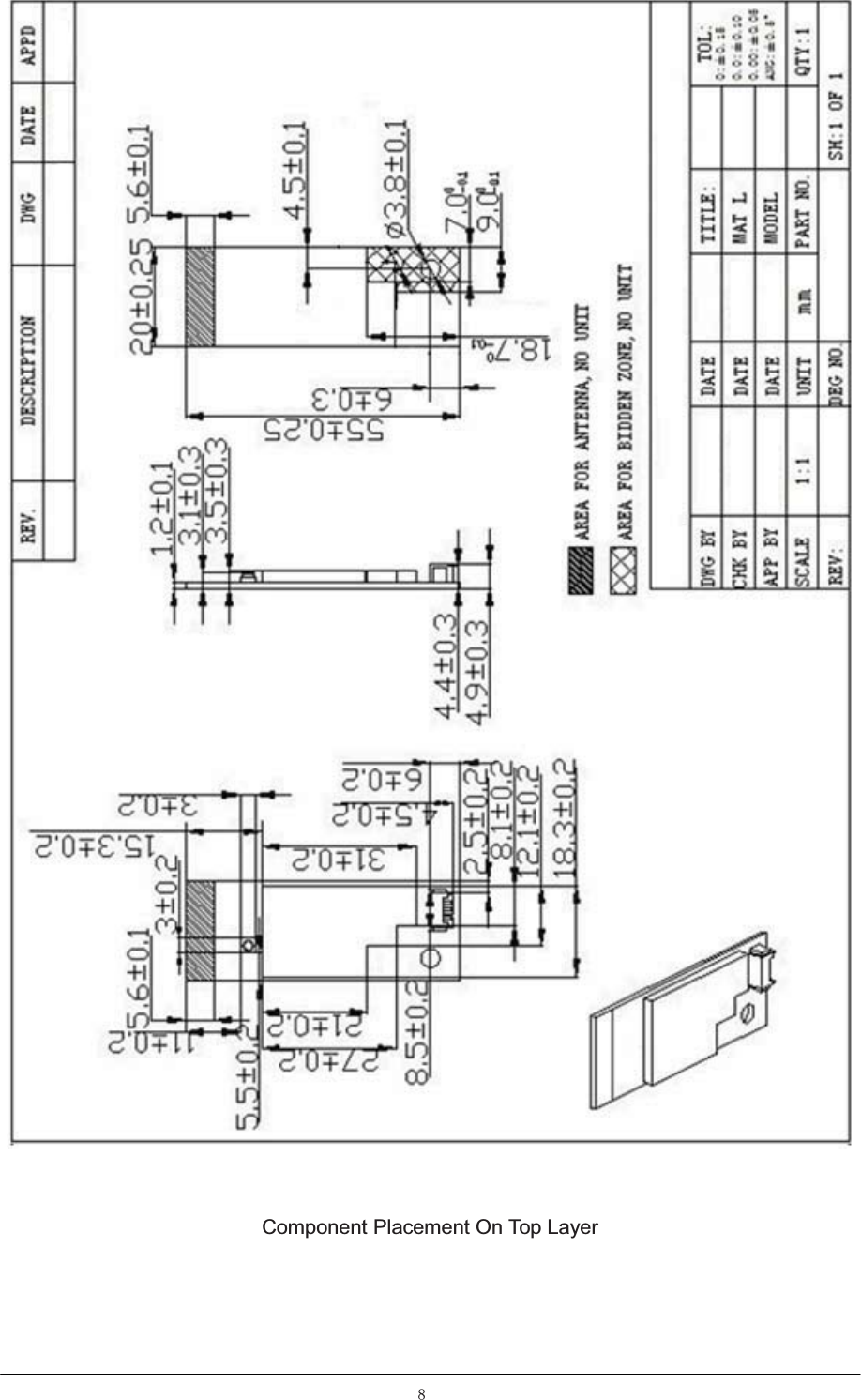
![5)& 5(6.¡f:60' 5 55)& 5(6¡f:60' 5 /56%-&+,3+LIUHT,QGXFWRUQ+fQ+P$&/+7166&KLOLVLQ // /56%-&+,3+LIUHT,QGXFWRUQ+fQ+P$&/+7166&KLOLVLQ // /50/%+32:(5,1'&3,1+/50X+f$VDPZKD // /)%$1-%:),/7(5&RPPRQ0RGH0&)*7¡9P$60'7DL\R / ;% ;7$/0+=330S)PP60'7.' 8 $7(,&'&'&=7370+]6LQJOH2XWSXW$627=,//7(. 8 $84'8#,&:/$11,&0784)10(',$7(. 8 &*&)3&&211PP607+RUL]RQWDOSDVWH3,1ePP - 3110:)59/)5PPMRLQWHGERDUG6XUIDFHLPPHUVLRQJROGSURFHVV3&% 03%% PP/HDGIUHHVKLHOGFRYHU 12.EfusecontentIP means interpolationAddressRegister NameValue00hCHIP ID 760102hEEPROM Version0D0004hMac Address(15:0)Unique06hMac Address(31:16)Unique08hMac Address(47:32)Unique0Ah Reserved FFFF0Ch Reserved FFFF0Eh Reserved FFFF10hASIC Reserved020112hUSB descriptor:Vendor ID04DA14hUSB descriptor:Product ID23FC](https://usermanual.wiki/Dalian-Golden-Hualu-Digital-Technology/WF4101/User-Guide-2483889-Page-17.png)