Dalian Golden Hualu Digital Technology WF4101 WIFI Module User Manual
Dalian Golden Hualu Digital Technology Co.,Ltd. WIFI Module
User manual
Project Name WIFI Module
Approval Sheet RVE. 1.1
Model NO. WF4101-R0
Panasonic Part NO. C5ZZZ0000096
Prepared by Reviewed by Approved by
Mickey Ye dongcheng Wen qing
Approval Sheet
USER MANUAL

1.RevisionHistory
DateDocument revisionChange Description
2014-10-30
REV1.0
The first
edition
2014-11-26
REV1.1
Increasingthecrystalmatch
report
2.ManufacturingInformation
Manufacture Country:
Made in china
Manufacturer:
Company Name: DaLian Golden Hualu Digital Technology Co., Ltd
Manufacturer Address:
No.1 Hua Road, Dalian High-Tech Industrial Zone, Dalian, China.
3.ProductOverview
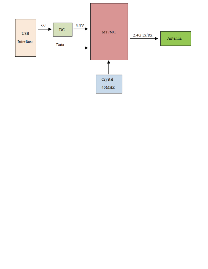
The WF4101-R0 802.11b/g/n module provides wireless modem functionality utilizing
direct sequence spread spectrum and OFDM/CCK technologyˈThis module is based on
Mediatek MT7601 solution which is integrated 2.4GHz IEEE802.11 b/g/n (MAC /baseband
/radio) and power amplifiers (PA).
3.1Applicationscope
The wireless LAN is compliant to IEEE802.11b and IEEE802.11g and IEEE802.11n
standard. The data rate of 802.11b is up to 11Mbps and fallback rates of 5.5, 2,

1Mbps.The data rate of 802.11g is up to 54Mbps and fallback rates of 48, 36, 24, 18, 12, 9,
6Mbps.The data rate of 802.11n HT20 with 800ns Gl is up to 65Mbps and fallback rates of
58.5, 52, 39, 26, 19.5, 13, 6.5Mbps; the data rate of 802.11n HT20 with 400ns Gl is up to
72.2Mbps and fallback rates of 65, 57.8, 43.3, 28.9, 21.7, 14.4, 7.2Mbps ;The data rate of
802.11n HT40 with 800ns Gl is up to 135Mbps and fallback rates of121.5, 108, 81, 54,
40.5, 27, 13.5Mbps.The data rate of 802.11n HT40 with 400ns Gl is up to 150Mbps and
fallback rates of 135, 120, 90, 60, 45, 30, 15Mbps.
This module is installed as a client device in BD Player PF and so on.
3.2Regulationofeachcountries
CE:
Applied Standard: EN 300 328 V1.8.1
STANDARD Test Item and
Limit
TRANSMITTER PARAMETERS
4.3.1 Equivalent isotropic Radiated Power
4.3.2 Peak Power Density ( DSSS, OFDM Equipment )
4.3.3 Frequency Range of Equipment Using Other Forms Of Modulation
4.3.4 Medium
A
ccess Protocol
4.3.5 Spurious Emissions (Operating)
4.3.6 Spurious Emissions (Standby)
RECEIVER PARAMETERS
4.3.7 Spurious Emissions
EN60950-1:2006+A11:20
09+A1: 2010
Safety
EN 301489-1 V1.8.1
(2008-04)
EN 301489-17 V2.1.1
(2009-05)
EMC
EU NB (0560) Certificate by Telefication
Note: Above regulations are representative examples. The module should get an
approval by more countries.
4.ModuleHardwareOverview
4.1Blockdiagram
The general H/W architecture is shown below Figure
4.2Features
¾ IEEE802.11b/g/n (1X1) based on MediaTek MT7601 solution, support HT40;
¾ USB 2.0 Interface, High and Full Speeds supported;
¾ Module is powered by the host with a 5.0V +/- 5% supply;
¾ One PCS PCB printed antenna;
¾ Two layers through hole PCB design with halogen free FR4 material
¾ Advanced Security: Supports 64/128 WEP, WPA/WPA2, WPA-PSK/WPA2-PSK
(TKIP/AES)
4.3InterfaceandConnector
¾ Pin definition:
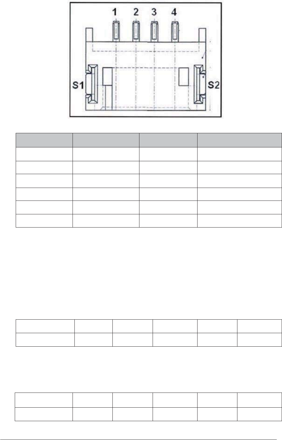
Pin Number Symbol Name
Status
Pin definition
1 VSS Ground
2 D+ I/O
USB positive date
3 D- I/O
USB negative date
4VDDP
USB +5v power input
S1 GND Ground
S2 GND Ground
5.ElectricalSpecification
5.1Absolutemaximumrating
Element Symbol
Min Typ Max Unit
DC supply voltage
VDD 4.5 5.0 5.5 (V)
5.2Recommendedoperatingrating
Element Symbol
Min Typ Max Unit
DC supply voltage
VDD 4.75 5.0 5.25 (V)
5.3DCCharacteristics
S
y
mbol Pa
r
amete
r
Min
T
y
p
Max Unit
VDD Supply voltage 4.75 5.0 5.25 (V)
Tx Current(1M/14dBm) -- 190 255 (mA)
Tx Current(6M/14dBm) -- 180 245 (mA)
Tx Current(11M/14dBm) -- 175 230 (mA)
Tx Current(54M/14dBm) -- 130 170 (mA)
Tx
Current(MCS0/14dBm/HT20)
-- 185 245 (mA)
Tx
Cu
r
rent
(
MCS0/12dBm/HT40
)
-- 175 230 (mA)
Tx
Current(MCS7/14dBm/HT20)
-- 130 170 (mA)
Tx
Current(MCS7/12dBm/HT40)
-- 115 150 (mA)
Rx Current -- 75 100 (mA)
5.4ESDInformation
Mode
Level
Unit
HBM
+/-2K
V
MM
+/-200
V
5.5EnvironmentStorageCondition
Environment condition
Temperature
Operating Temperature˖0 deg.C ~ 55 deg.C
Storage Temperature˖-40 deg.C ~ 80 deg.C
Humidity O
p
eratin
g
Humidit
y
: 20% ~ 90%
Stora
g
eHumidit
y
: 20% ~ 90%

6.MechanicalSpecifications
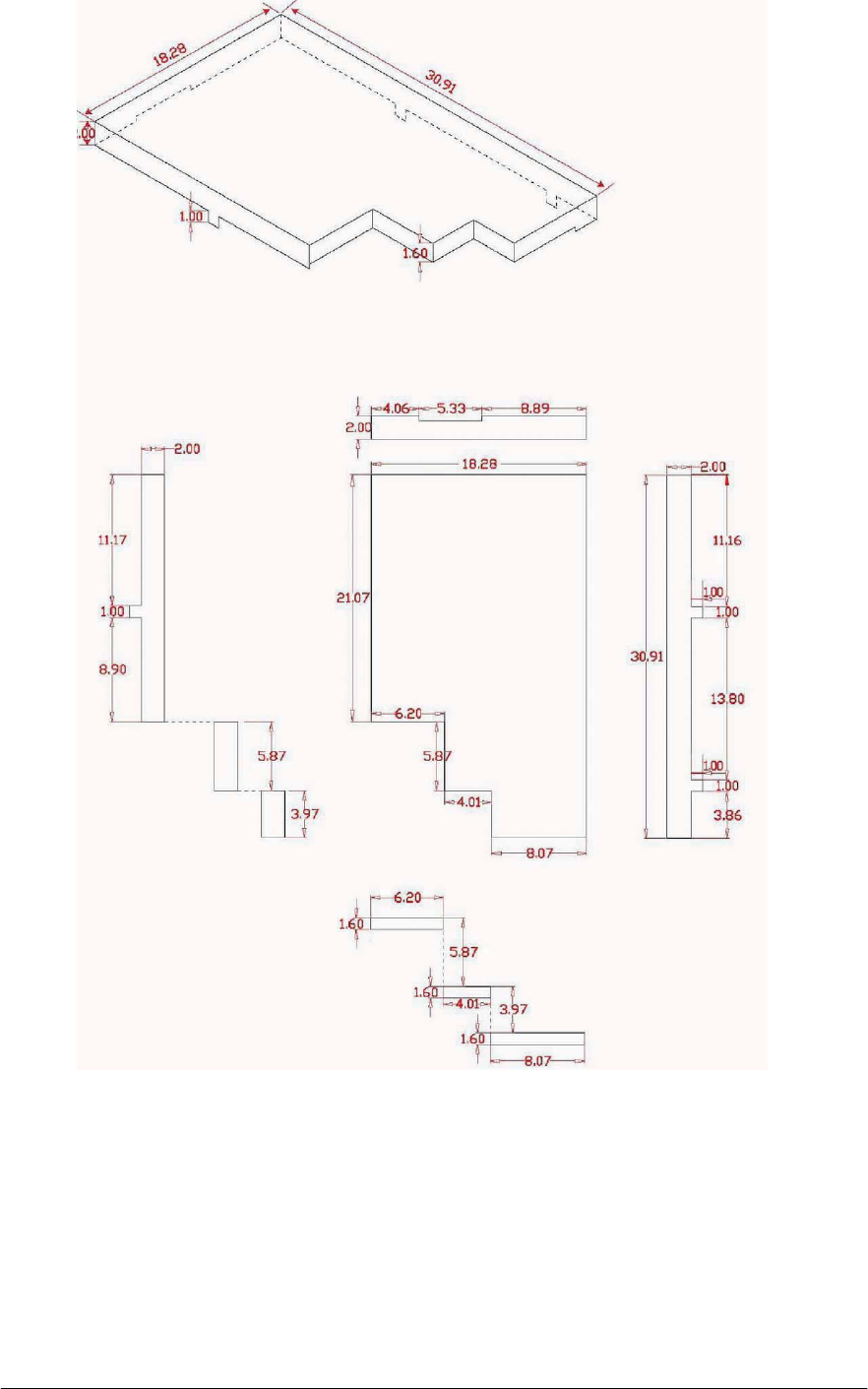
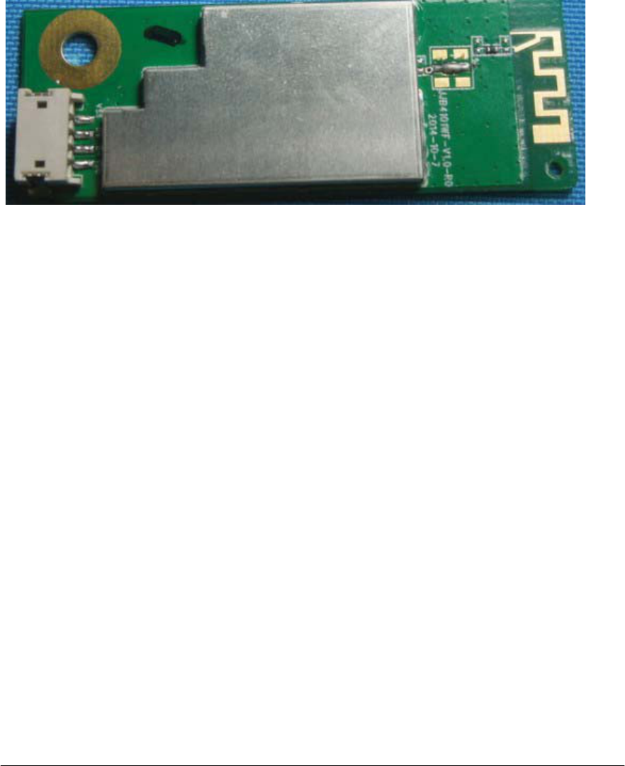
6.1ShieldingCoverDimension
Dimension (LXWXH): 30.91mm x 18.28mm x 2mm
MATERIAL:
Copper-Nickel-Zinc
Alloy
Thickness: 0.2mm
6.2PCBAssemblyDimension
Dimension(W×L): 55mm×20mm
PCB Two layer HF-FR4 design
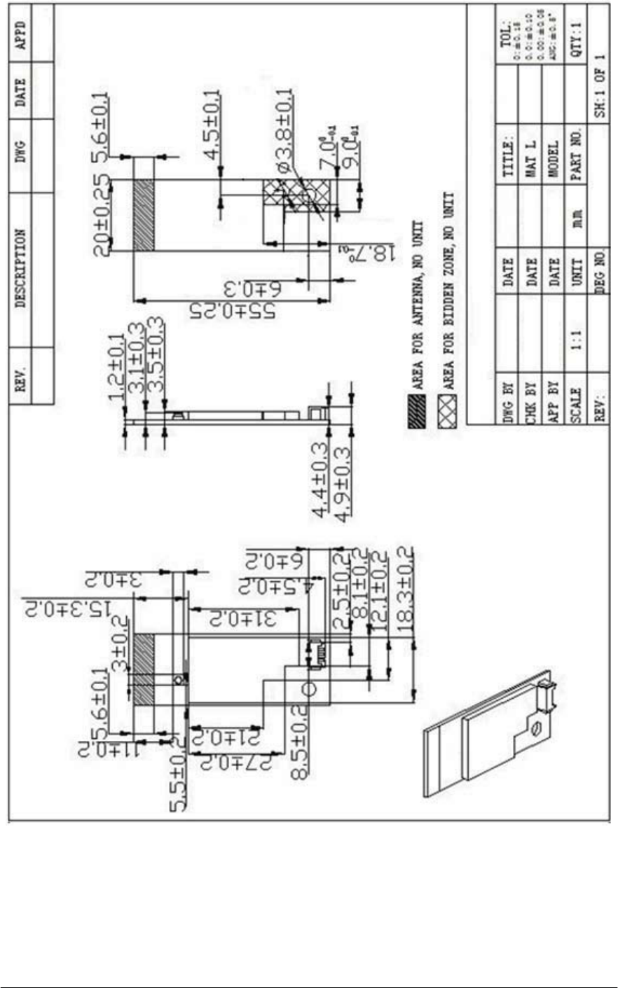
Component Placement On Top Layer
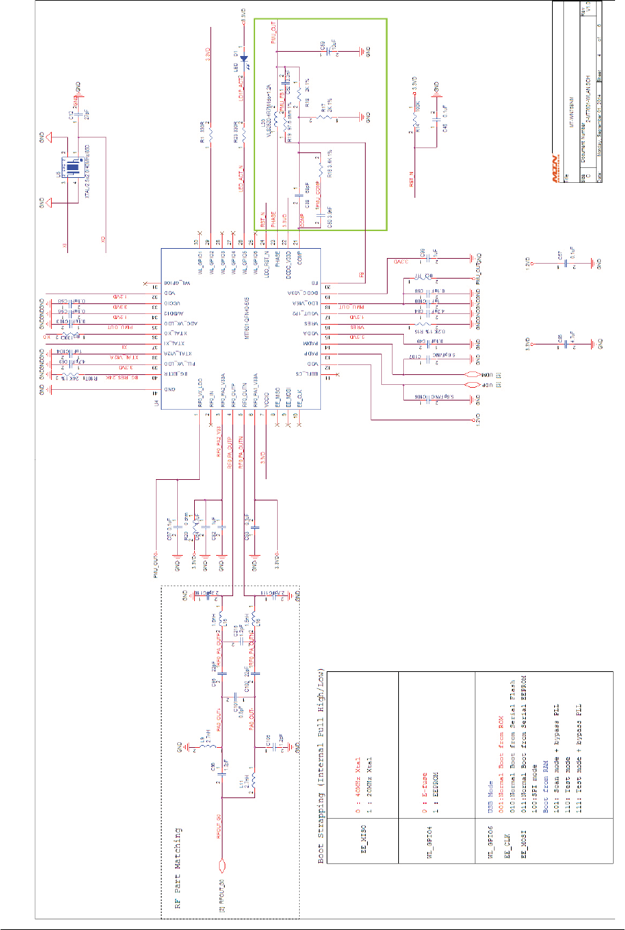
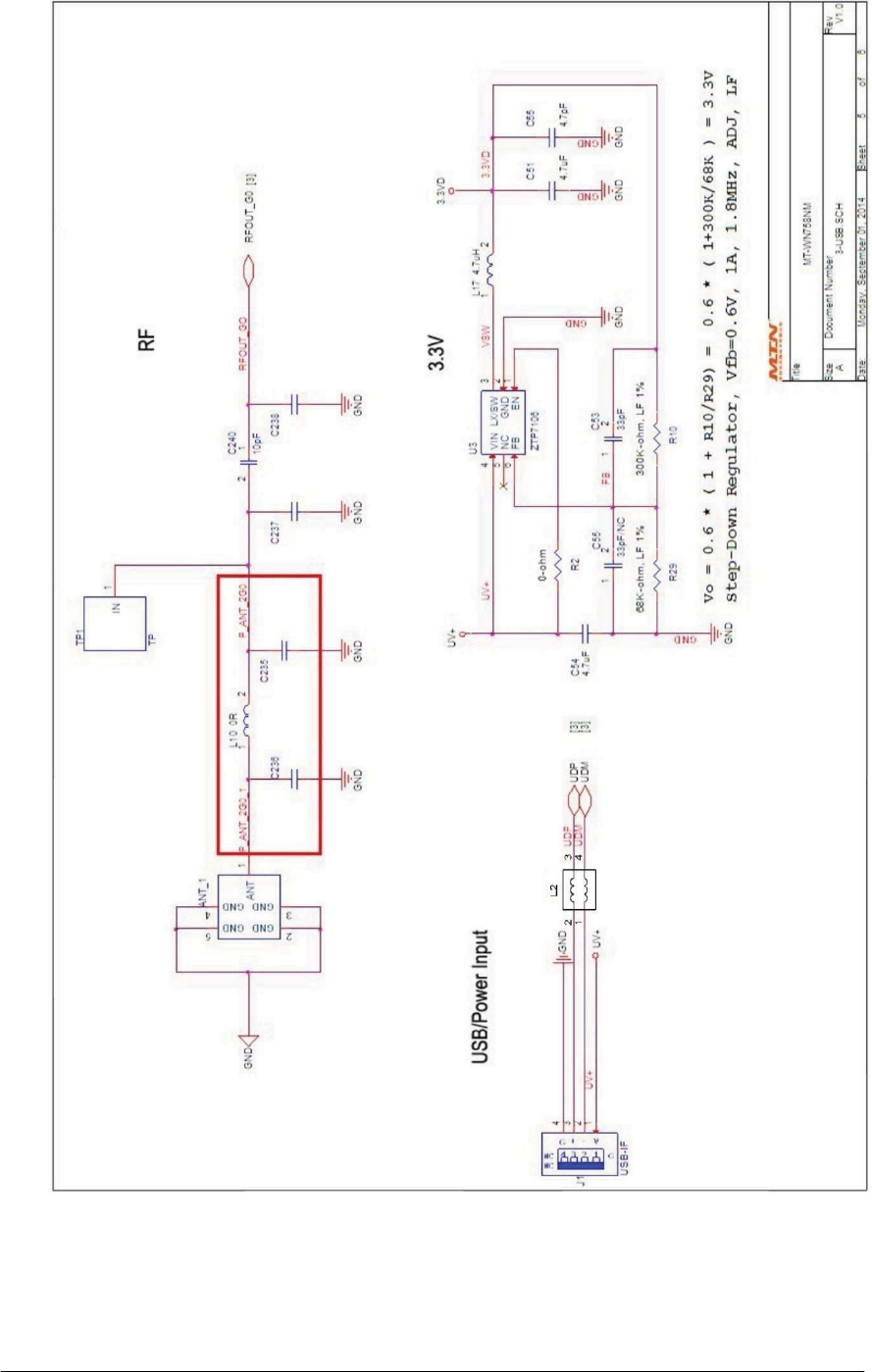
7.Schematics
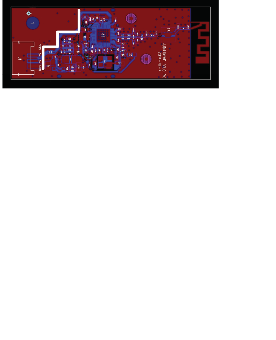
8.LayoutPattern
TOP Layer
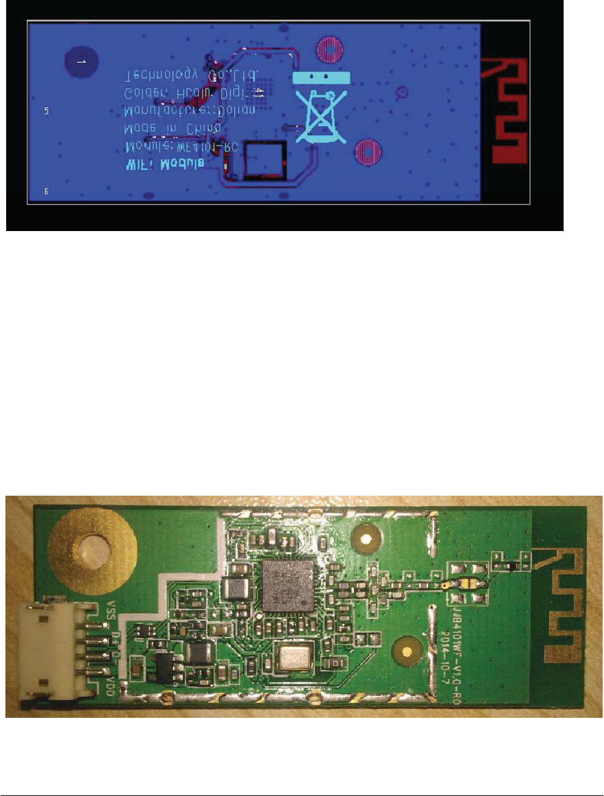
Bottom Layer
Top View
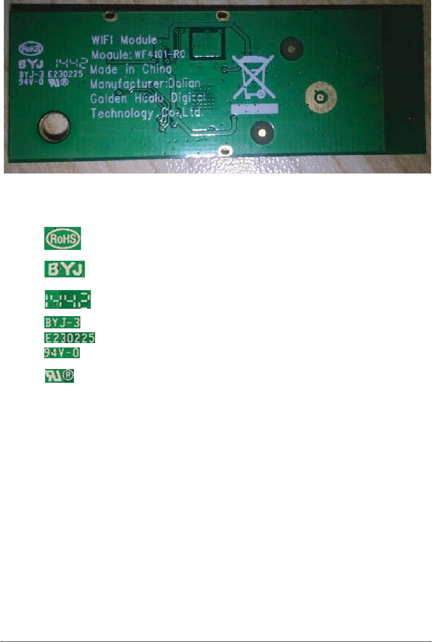
Bottom View
Description:
RoHS mark
PCB Vendor Logo
Manufacturing Data code (2014 Year, 42 week)
PCB Vendor material certification number
UL Number
Flammability
UL Logo
9.Labelinformation
9.1MACIDLabel
Label stick position:
(Picture just for reference)
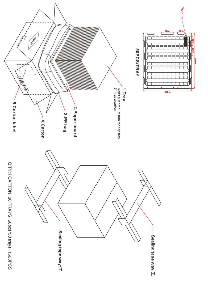
10.Packageinformation
10.1CartonASSY

5)& 5(6.¡f:60' 5
55)& 5(6¡f:60' 5
/56%-
&+,3+LIUHT,QGXFWRUQ+fQ+P$
&/+7166&KLOLVLQ
//
/56%-
&+,3+LIUHT,QGXFWRUQ+fQ+P$
&/+7166&KLOLVLQ
//
/50/%+
32:(5,1'&3,1+/50X+f$
VDPZKD
//
/)%$1-%:
),/7(5&RPPRQ0RGH0&)*7¡9
P$60'7DL\R
/
;% ;7$/0+=330S)PP60'7.' 8
$7(
,&'&'&=7370+]6LQJOH2XWSXW$
627=,//7(.
8
$84'8
#,&:/$11,&0784)10(',$7(.
8
&*&
)3&&211PP607+RUL]RQWDOSDVWH3,1
ePP
-
3110
:)59/)5PP
MRLQWHGERDUG6XUIDFHLPPHUVLRQJROG
SURFHVV3&%
03%% PP/HDGIUHHVKLHOGFRYHU
12.Efusecontent
IP means interpolation
Address
Register Name
Value
00h
CHIP
ID 7601
02h
EEPROM Version
0D00
04h
Mac Address(15:0)
Unique
06h
Mac Address(31:16)
Unique
08h
Mac Address(47:32)
Unique
0Ah Reserved FFFF
0Ch Reserved FFFF
0Eh Reserved FFFF
10h
ASIC Reserved
0201
12h
USB descriptor:Vendor ID
04DA
14h
USB descriptor:Product ID
23FC

16h
ASIC Reserved
0000
18h
ASIC Reserved
004A
1Ah
ASIC Reserved
0001
1Ch
ASIC Reserved
5080
1Eh
ASIC Reserved
0008
20h
ASIC Reserved
0003
22h
ASIC Reserved
0002
24h
ASIC Reserved
0000
26h
USB String lndex Head
01FF
28h
USB String lndex
6040
2Ah
USB String lndex
FF80
2Ch
USB String lndex
FFFF
2Eh
USB String lndex
FFFF
34h
NIC Configuration 0
FF11
36h
NIC Configuration 1
1004
38h
Country Region 2.4G band
FFFF
3Ah
LED
Mode 012C
3Ch Reserved FFFF
3Eh Reserved 9999
40h Reserved 888C
42h
NIC Configuration 2
07FF
44h
Extemal LNA gain for 2.4G Band
0008
46h
2.4G RSSIO offset
0000
48h
TX mixer gain setting for 2.4Ghz BAND
0000
4Eh
Reserved for use
0000
50h
20M/40M BW Power delta for 2.4G
0083
band
52h
Channel 2 TX0 power (ALC)
0000
54h
Channel 4 TX0 power (ALC)
0000
56h
Channel 6 TX0 power (ALC)
0000
58h
Channel 8 TX0 power (ALC)
0000
5Ah
Channel 10 TX0 power (ALC)
0000
5Ch
Channel 12 TX0 power (ALC)
0000
5Eh
Channel 14 TX0 power (ALC)
0000
6Eh
TX0 TSSI offset for group0
0080
70h
TX0 TSSI offset for group2
0000
75h
2.4G TSSL OFFSET COMPENSATION
0000
D0h
25C TEMP SENSOR CALIBRABON
F920
DAh
Frequenoy offset compensation
0000
DEh
TX power for CCK 5.5M/11M
0002
E0h
TX power for OFDM 12M/18M
3A3A
E2h
TX power for OFDM 48M/54M
3B3B
E4h
TX power for HT MCS=2,3
3A3A

E6h
TX power for HT MCS=6,7
3C3C
E8h
TX power for HT MCS=10,11
0000
EAh
TX power for HT MCS=14,15
0002
ECh
TX power for STBC MCS=2,3
0000
EEh
TX power for STBC MCS=6,7
0002
110h
Reserved for Customer
FFFF
112h
Reserved for Customer
FFFF
114h
Reserved for Customer
FFFF
116h
Reserved for Customer
FFFF
118h
Configured 2.4G Channels
FFFF
11Eh
Reserved for Customer
FFFF
140h-17fh
USB String Descriptor
FFFF
13.ReliabilityTestReport
Package Reliability Test Report
NO.
Item
Test Condition
Unit
Test Period Test Resul
t
1
Package Drop Tset 1m.one corner,three edges,six faces 1 carton
1.Visual
Inspection-Match with
IPC-A-610D
2. Function
test
Pass
Pass
2
Package Shock Test
Mximum Acceleration is 200G
Duration
time is 2ms 3 times per each
Direction
then totall 3 x 6 directions =
18
times
1 carton
1.Visual
Inspection-Match
with
IPC-A-610C
2. Function
test
Pass
Pass
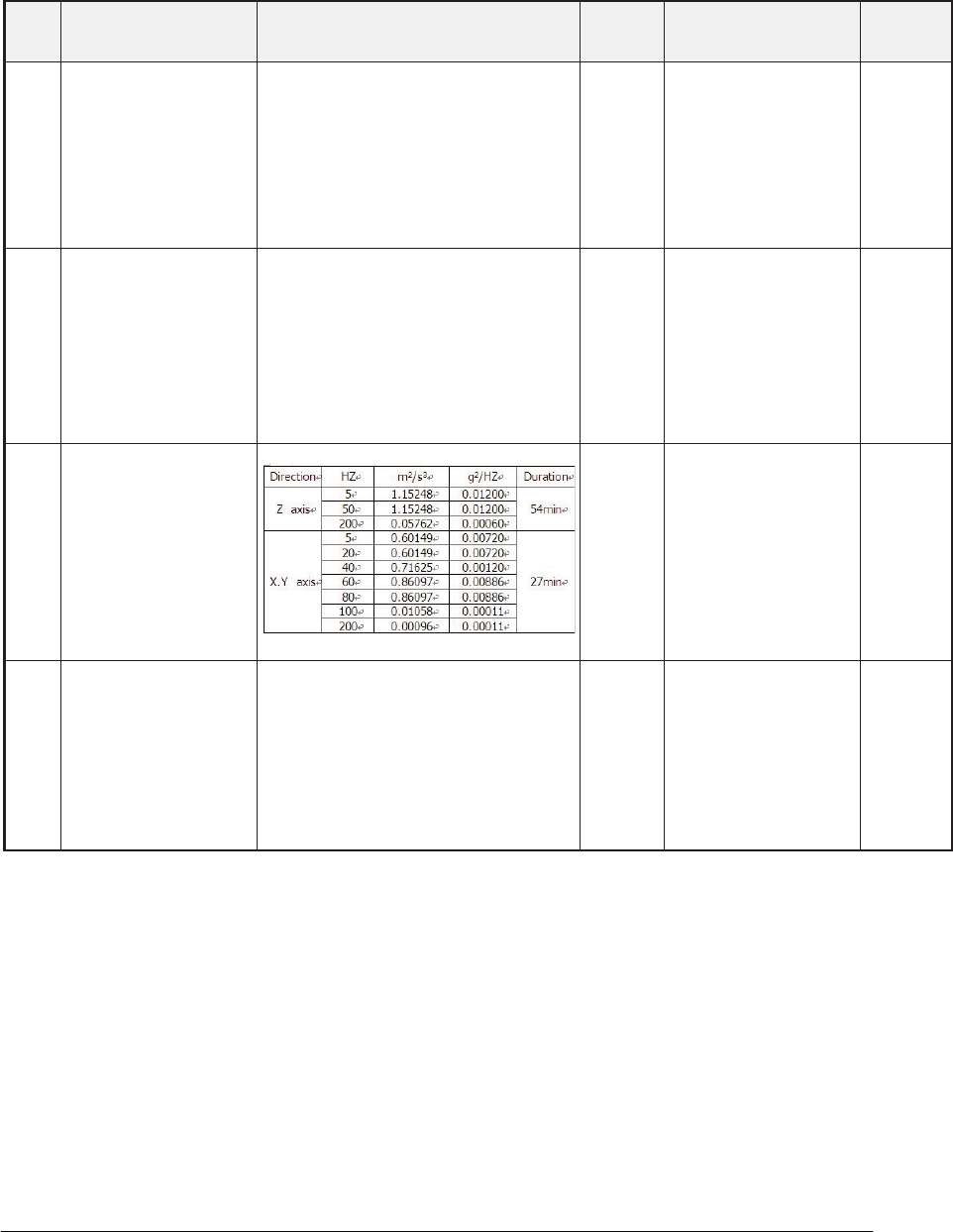
3
Package Vibration Test 1 carton
1.Visual
Inspection-Match
with
IPC-A-610C
2. Function
test
Pass
Pass
4
Package Storage at
High
Temperature and
High Humidity
Temperature:60
ć
Humidity:90%R.H
Duration:120hrs
1 carton
1.Visual
Inspection-Match
with
IPC-A-610C
2. Function
test
Pass
Pass
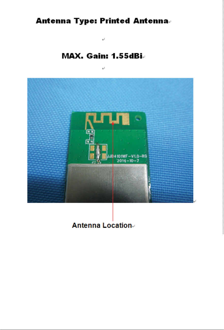
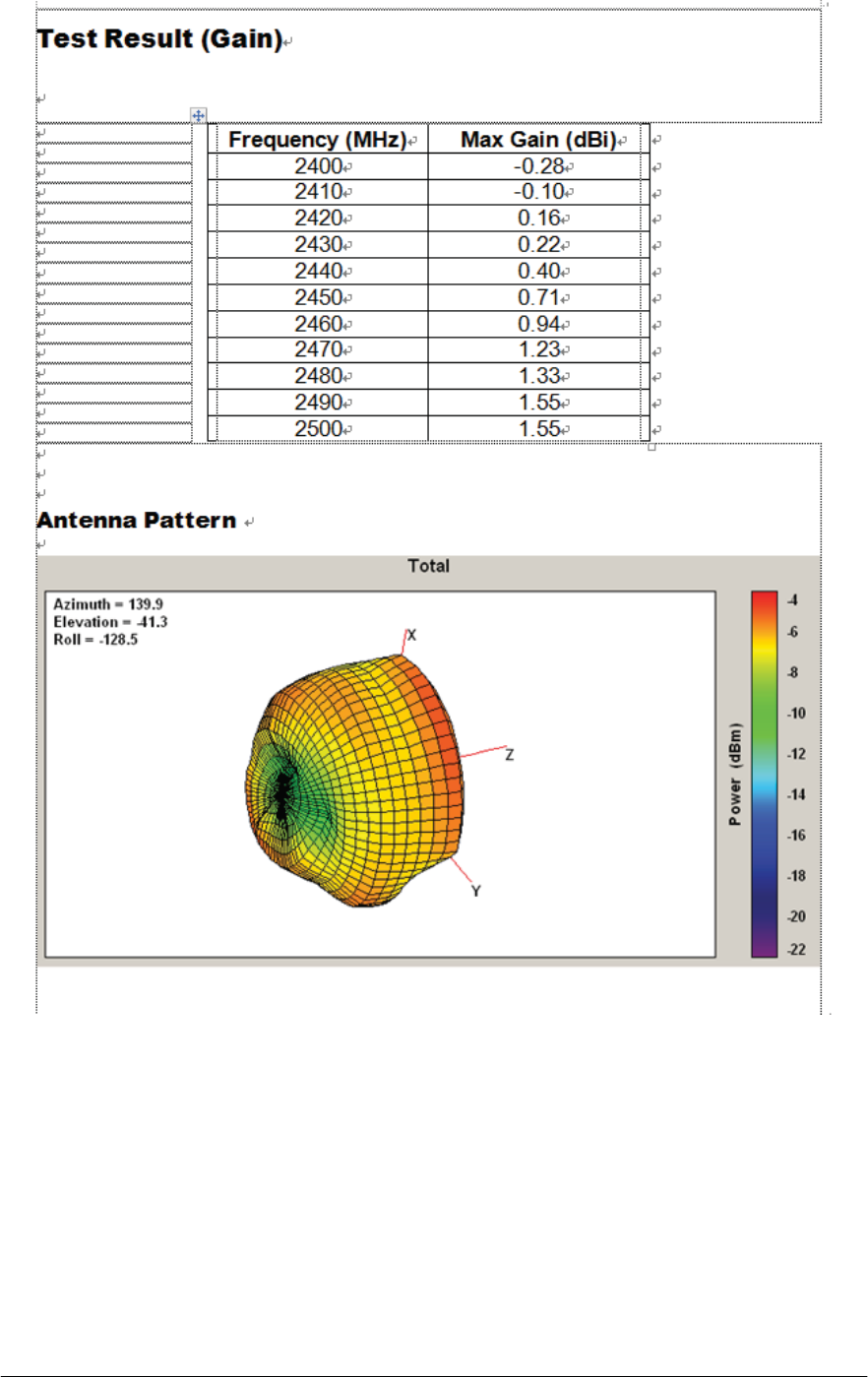
15.AntennaSpecification
16.FCC
This device complies with part 15 of the FCC Rules. Operation is subject to the following two

conditions: (1) This device may not cause harmful interference, and (2) this device must
accept any interference received, including interference that may cause undesired operation.
Changes or modifications not expressly approved by the party responsible for compliance
could void the user's authority to operate the equipment.
NOTE: This equipment has been tested and found to comply with the limits for a Class B digital
device, pursuant to Part 15 of the FCC Rules. These limits are designed to provide reasonable
protection against harmful interference in a residential installation. This equipment generates,
uses and can radiate radio frequency energy and, if not installed and used in accordance with
the instructions, may cause harmful interference to radio communications. However, there is
no guarantee that interference will not occur in a particular installation. If this equipment does
cause harmful interference to radio or television reception, which can be determined by turning
the equipment off and on, the user is encouraged to try to correct the interference by one or
more of the following measures:
-- Reorient or relocate the receiving antenna.
-- Increase the separation between the equipment and receiver.
-- Connect the equipment into an outlet on a circuit different from that to which the receiver is
connected.
-- Consult the dealer or an experienced radio/TV technician for help.
FCC Radiation Exposure Statement
The modular can be installed or integrated in mobile or fix devices only. This modular cannot
be installed in any portable device, for example, USB dongle like transmitters is forbidden.
This modular complies with FCC RF radiation exposure limits set forth for an uncontrolled
environment. This transmitter must not be co-located or operating in conjunction with any other
antenna or transmitter. This modular must be installed and operated with a minimum distance
of 20 cm between the radiator and user body.
If the FCC identification number is not visible when the module is installed inside another
device, then the outside of the device into which the module is installed must also display a
label referring to the enclosed module. This exterior label can use wording such as the
following: “Contains Transmitter Module FCC ID:2ADKJWF4101 Or Contains FCC ID:
2ADKJWF4101 ”

when the module is installed inside another device, the user manual of this device must
contain below warning statements;
1. This device complies with Part 15 of the FCC Rules. Operation is subject to the following
two conditions:
(1) This device may not cause harmful interference.
(2) This device must accept any interference received, including interference that may cause
undesired operation.
2. Changes or modifications not expressly approved by the party responsible for compliance
could void the user's authority to operate the equipment.
The devices must be installed and used in strict accordance with the manufacturer's
instructions as described in the user documentation that comes with the product
Canada Statement
This device complies with Industry Canada licence-exempt RSS standard(s). Operation is
subject to the following two conditions: (1) this device may not cause interference, and (2) this
device must accept any interference, including interference that may cause undesired
operation of the device.
Le présent appareil est conforme aux CNR d'Industrie Canada applicables aux appareils radio
exempts de licence. L'exploitation est autorisée aux deux conditions suivantes : (1) l'appareil
ne doit pas produire de brouillage, et (2) l'utilisateur de l'appareil doit accepter tout brouillage
radioélectrique subi, même si le brouillage est susceptible d'en compromettre le
fonctionnement.
IC Radiation Exposure Statement
The modular can be installed or integrated in mobile or fix devices only. This modular cannot
be installed in any portable device, for example, USB dongle like transmitters is forbidden.
This modular complies with IC RF radiation exposure limits set forth for an uncontrolled
environment. This transmitter must not be co-located or operating in conjunction with any other
antenna or transmitter. This modular must be installed and operated with a minimum distance
of 20 cm between the radiator and user body. Cette modulaire doit être installé et utilisé à une
distance minimum de 20 cm entre le radiateur et le corps de l'utilisateur.
If the IC number is not visible when the module is installed inside another device, then the
outside of the device into which the module is installed must also display a label referring to the
enclosed module. This exterior label can use wording such as the following: “Contains IC:
12493A-WF4101”
when the module is installed inside another device, the user manual of this device must
contain below warning statements;
1. This device complies with Industry Canada’s licence-exempt RSSs. Operation is subject to
the following two conditions:

(1) This device may not cause interference; and
(2) This device must accept any interference, including interference that may cause undesired
operation of the device.
2. Cet appareil est conforme aux CNR exemptes de licence d'Industrie Canada . Son
fonctionnement est soumis aux deux conditions suivantes :
( 1 ) Ce dispositif ne peut causer d'interférences ; et
( 2 ) Ce dispositif doit accepter toute interférence , y compris les interférences qui peuvent
causer un mauvais fonctionnement de l'appareil.
The devices must be installed and used in strict accordance with the manufacturer's
instructions as described in the user documentation that comes with the product.
17.NCC
ᴀ⫶કヺড়Ԣࡳ⥛䳏⊶䔏ᇘᗻ䳏″ㅵ⧚䕺⊩˖
कѠṱ
㍧ᔶᓣ䁡䄝ড়ḐПԢࡳ⥛ᇘ丏䳏″ˈ䴲㍧䀅ৃˈ݀ৌǃଚ㰳Փ⫼㗙ഛϡᕫ᪙㞾䅞丏⥛ǃࡴ
ࡳ⥛䅞ॳ䀁㿜П⡍ᗻঞࡳ㛑DŽ
कಯṱ
Ԣࡳ⥛ᇘ丏䳏″ПՓ⫼ϡᕫᕅ䷓亯㟾ᅝܼঞᑆড়⊩䗮ֵ˗㍧ⱐ⧒᳝ᑆ⧒䈵ᰖˈឝゟेذ⫼ˈ
Ϻᬍ㟇⛵ᑆᰖᮍⱘ㑐㑠Փ⫼DŽ
ࠡ䷙ড়⊩䗮ֵˈᣛձ䳏ֵ㽣ᅮὁП⛵㎮䳏ֵDŽԢࡳ⥛ᇘ丏䳏″䷜ᖡফড়⊩䗮ֵᎹὁǃ⾥ᅌঞ
䝿Ⱆ⫼䳏⊶䔏ᇘᗻ䳏″䀁٭ПᑆDŽ
ᴀ㌘ᮐপᕫ䁡䄝ᕠˈᇛձ㽣ᅮᮐ㌘ᴀ储῭⼎ᆽ倫ড়Ḑ῭㈸, Ϻ㽕∖ᑇৄᒴଚᮐᑇৄϞ῭⼎
Njᴀ⫶કܻᇘ丏㌘ XXXyyyLPDzzzzx
䳏⺕⊶Ჱ䴆䞣 MPE ῭⑪ؐ 1mW/CM2ˈ䗕␀⫶કᆺ␀ؐ⚎˖0.05444mW/CM2