Damm Cellular Systems A S 104012 410 MHZ TRANSCEIVER MODULE User Manual TetraFlex 7 5 Manual
Damm Cellular Systems A/S 410 MHZ TRANSCEIVER MODULE TetraFlex 7 5 Manual
Contents
- 1. User Manual - 1
- 2. User manual - 2
- 3. User Manual - 3
- 4. User Manual - 4
- 5. Warning statements for user's manual
- 6. Notes to installer for user manual
- 7. Revised pages 4 and 5 of the user's manual 11 01 2012
- 8. User addendum 4 carrier 11 01 12
- 9. User addendum 8 carrier 11 01 2012
- 10. Note to installers to be placed in user manual
User Manual - 1

TetraFlex® V7.5
US DRAFT version
Manual version 1.01
27.01.2012
The information contained in this document is the property of Damm Cellular Systems A/S. This document is
subject to copyright and shall not be published or reproduced, in whole or in part, without the written permission
of Damm Cellular Systems A/S.
© 2010 Damm Cellular Systems A/S. All rights reserved.
Møllegade 68, DK-6400 Sønderborg, Denmark
Phone: +45 74 42 35 00, Fax: +45 74 42 30 31,
E-Mail: dcs@damm.dk,

Doc. No.
Rev.
Date
DRAFT
1.01
2012-01-27
Damm Cellular Systems A/S, Denmark
TetraFlex® 7.5 Manual - Introduction
TetraFlex® 7.5 Manual 2
http://www.damm.dk
INTRODUCTION
This manual is intended for installation and maintenance of BS4xx TetraFlex® Base Station,
including additional units, installation software, and how to configure the system for
operational use.
Remark: TetraFlex® ver. 7.5 is not compatible with earlier versions! Please follow the update
instructions or contact DAMM support if you have systems with older software versions.
Doc. No.
Rev.
Date
DRAFT
1.01
2012-01-27
Damm Cellular Systems A/S, Denmark
TetraFlex® 7.5 Manual - Introduction
TetraFlex® 7.5 Manual 3
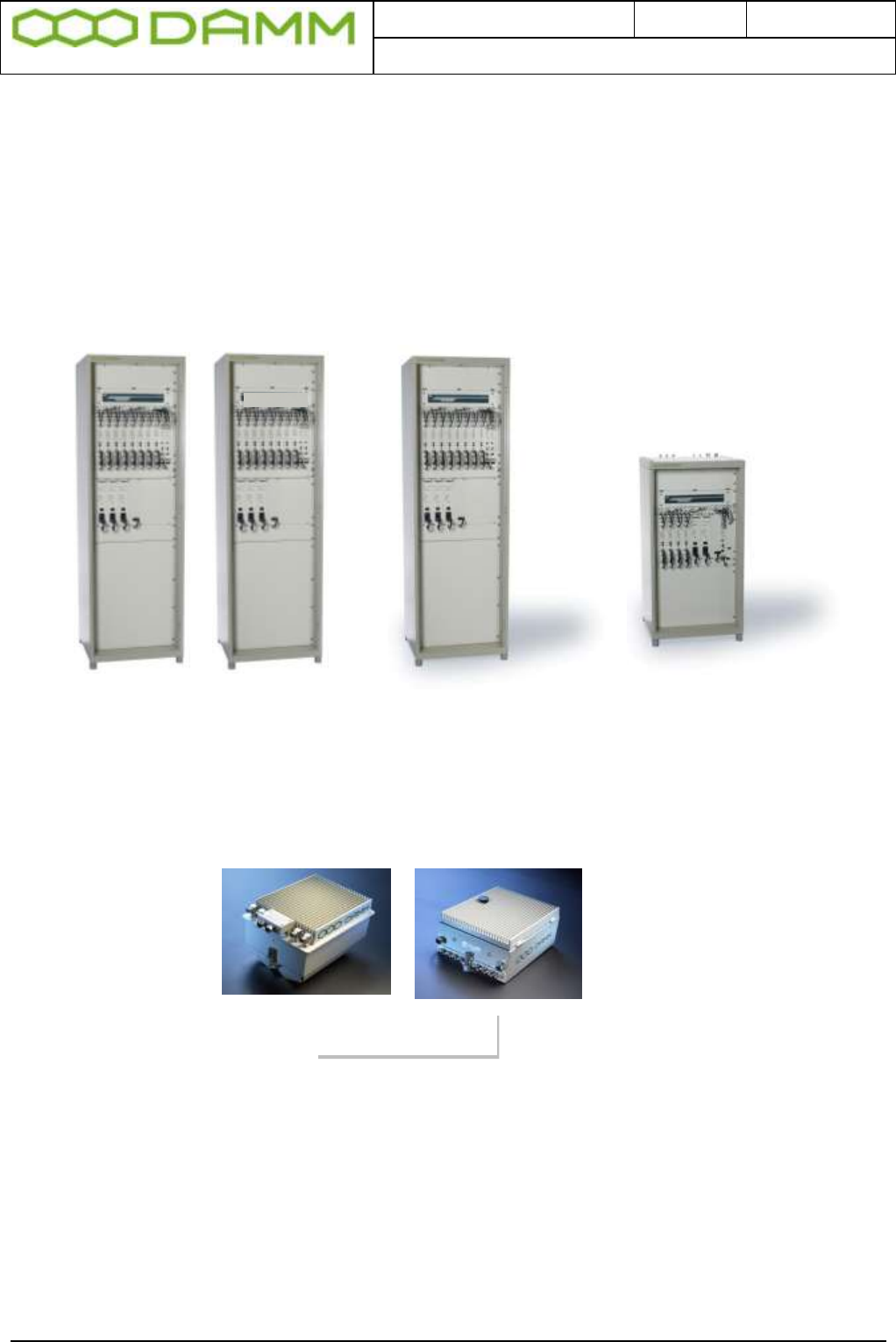
Indoor Base station models
BS411
BS414
Max. 8 carriers Max. 4 carriers
Max. 16 carriers
Outdoor station
BS421 + SB 421
It is recommended that engineers doing the installation and configuration of a BS4xx have
practical experience in installation of radio and computer systems, and have made
themselves familiar with the BS4xx equipment through appropriate DAMM training courses
and study of the content of this manual.
This installation guide covers the installation of indoor as well as outdoor Base Stations as
well as single units. Please skip the sections, which are not relevant for the actual case.
Max. 4 carriers
Doc. No.
Rev.
Date
DRAFT
1.01
2012-01-27
Damm Cellular Systems A/S, Denmark
TetraFlex® 7.5 Manual - Introduction
TetraFlex® 7.5 Manual 4
The manual is divided into more sections which may be printed separately. When doing so
please print the Table of contents, introduction, update sheets and Index (all pages prior to
page 1-1 and after page 4-x) and insert these in the printed section
IMPORTANT:
Updates / changes / important information related to the TetraFlex® system and software
may be downloaded from the protected part of www.damm.dk
Please check this URL for updated information before attempting to install or correct errors
NOTE: Chapters marked with a indicate areas where special care must be taken to
avoid personal injury or damage to the equipment.
Before starting installation and configuration, please read the entire
manual carefully.
NOTE: It is the responsibility of the system owner / operator to ensure
that only authorized service persons has access to the keys / inside
circuits of the SB412 / BS4xx.
NOTE: It is the responsibility of the system owner / operator to ensure
that all local legislation, rules and regulations are complied with.
The SB412 / BS4xx are protected by internal fuses. Always replace with
fuses of equivalent value and type.
General Warning
This manual contains important safety and operational information. Please read and follow
the instructions in this manual. Failure to do so could be hazardous and result in damage to
your device.
Changes and modifications to this device not expressly proved by DAMM could void the
user’s authorization to operate this device
FCC Regulations
The DAMM developed device mentioned in this User Manual fulfills the below statements
according to FCC/IC warning statements:
This device complies with part 15 of the FCC Rules. Operation is subject to the following two
conditions: (1) This device may not cause harmful interference, and (2) this device must
accept any interference received, including interference that may cause undesired operation

Doc. No.
Rev.
Date
DRAFT
1.01
2012-01-27
Damm Cellular Systems A/S, Denmark
TetraFlex® 7.5 Manual - Reference documents
TetraFlex® 7.5 Manual 5
RF Exposure
The DAMM developed transmitting devices mentioned in this User Manual have the Nemko
approval concerning “Maximum Permissible Exposure Calculations” which are the European
limits for maximum permissible exposure defined in the document 1995/519/EC, Council
Recommendation of 12. July 1999. The results are to be found in the Nemko Document
128948/5 in the appendix of this User Manual.
Antennas
The outside antenna connected to this device must be installed on an outdoor permanent
structure with a separation of at least 20 feet from all persons during normal operation.
Notice
Do not modify any part of this device for any reason
Do not place any combustible material near the transceiver
Do not spray any liquid over the device
Ensure that the power and antenna connections are securely made, using cables
recommended and with excess capacity for the power being utilized.
REFERENCE DOCUMENTS
For detailed information’s regarding the TetraFlex® release and features supported, please
consult the documents listed below:
No.:
Document Title
Document Contents
1
TetraFlex v7.5 System description.pdf *
TetraFlex® system overview
2
TetraOM_7.5.pdf
TetraFlex® OM manual
3
TetraFlex_RN_7.52_2011-09-30_02.pdf *
TetraFlex® system release note
4
TetraFlex 7.4x to 7.5 update.pdf
Update guideline for ver.7.4x to 7.5
5
TetraFlex 7.5 BS41x redundant setup.pdf
Redundancy sw setup guideline for
BS41x
*) These documents is a part of the TetraFlex® release and placed in the C:\tetra\Active\Doc directory
All documents can be found on www.damm.dk extranet.
TETRAFLEX® MANUAL BREAKDOWN
Section
Description
Level
Part 1
Physical hardware installation
Tech
Part 2
Software installation and configuration of software and system
Tech
Part 3
User manual intended for operators and non technical personnel
User
Part 4
Technical reference
Tech
Part 5
Hardware Units Ref.
Tech
Part 6
List of figures and Alphabetic index
All

Doc. No.
Rev.
Date
DRAFT
1.01
2012-01-27
Damm Cellular Systems A/S, Denmark
TetraFlex® 7.5 Manual - TetraFlex® Manual breakdown
TetraFlex® 7.5 Manual 6

Doc. No.
Rev.
Date
DRAFT
1.01
2012-01-27
Damm Cellular Systems A/S, Denmark
TetraFlex® 7.5 Manual - TetraFlex® Manual breakdown
TetraFlex® 7.5 Manual 7
TABLE OF CONTENTS
Introduction ................................................................................................................................................ 2
Reference documents .................................................................................................................................. 5
TetraFlex® Manual breakdown ..................................................................................................................... 5
Revision .................................................................................................................................................... 17
Abbreviations / Definitions ........................................................................................................................ 19
PART-1: HARDWARE INSTALLATION ............................................................................................... 1-1
1.1 SB421 .............................................................................................................................................. 1-2
1.1.1 Environmental / climatic requirements ................................................................................................... 1-2
1.1.2 Placement ................................................................................................................................................. 1-2
1.1.3 Grounding ................................................................................................................................................. 1-2
1.1.4 SB421 basic elements ............................................................................................................................... 1-3
1.1.4.1 SB421 Variants ...................................................................................................................................... 1-3
1.1.4.2 Mechanical Lock .................................................................................................................................... 1-3
1.1.4.3 Power supply / charger ......................................................................................................................... 1-3
1.1.4.4 BSC421 Base Station Controller ............................................................................................................ 1-4
1.1.4.4.1 SB421 Processor board internal backup battery................................................................................ 1-4
1.1.4.4.2 Storage unit ........................................................................................................................................ 1-4
1.1.4.4.3 BSC connections ................................................................................................................................. 1-5
1.1.4.4.4 BSC421 LED’s and Fuses ..................................................................................................................... 1-5
1.1.4.5 Interconnection Board .......................................................................................................................... 1-6
1.1.4.5.1 Connections ........................................................................................................................................ 1-6
1.1.4.5.2 Switches ............................................................................................................................................. 1-6
1.1.4.5.3 LED’s ................................................................................................................................................... 1-7
1.1.4.5.4 TR1/TR2 connection module .............................................................................................................. 1-7
1.1.4.5.5 PS Connection to TR1 and TR2 ........................................................................................................... 1-8
1.1.4.5.6 LAN Connection to TR1 and TR2 ........................................................................................................ 1-8
1.1.4.5.7 LAN/WAN/SEC/Alarm Connection module ........................................................................................ 1-8
1.1.4.5.8 Connections ........................................................................................................................................ 1-8
1.1.4.5.9 Redundant SB421 operation .............................................................................................................. 1-9
1.1.4.5.10 Temperature sensor (TS) Connection .............................................................................................. 1-9
1.1.4.5.11 Alarm Connection ............................................................................................................................. 1-9
1.1.4.6 Mains Connection block ........................................................................................................................ 1-9
1.1.4.7 Internal -48 battery assembly (option) ............................................................................................... 1-10
1.1.4.8 External -48 battery kit (option) connection block ............................................................................. 1-10
1.1.5 HW change for redundant SB421 / 3 and 4 carrier operation ............................................................. 1-11
1.1.6 SB421 Internal Battery Assembly ........................................................................................................... 1-13
1.1.6.1 Battery kit maintenance ...................................................................................................................... 1-13
1.1.6.1.1 Installing batteries ............................................................................................................................ 1-13
1.1.7 External -48 battery kit (option) connection block ................................................................................ 1-15
1.2 BS421 ............................................................................................................................................ 1-17
1.2.1 Environmental / climatic requirements ................................................................................................. 1-17
1.2.2 Placement ............................................................................................................................................... 1-17
1.2.3 Grounding ............................................................................................................................................... 1-17
1.2.4 BS421 main components........................................................................................................................ 1-18
1.2.5 Attaching RX/TX antennas ...................................................................................................................... 1-19

Doc. No.
Rev.
Date
DRAFT
1.01
2012-01-27
Damm Cellular Systems A/S, Denmark
TetraFlex® 7.5 Manual - TetraFlex® Manual breakdown
TetraFlex® 7.5 Manual 8
1.2.5.1 Single Carrier BS installation recommendation (1 x BS421) ............................................................... 1-19
1.2.5.2 Dual Carrier BS installation recommendation (2 x BS421) .................................................................. 1-19
1.2.6 Power connection to SB421 ................................................................................................................... 1-20
1.2.6.1 System Connector ............................................................................................................................... 1-21
1.2.6.1.1 Easy connection scheme .................................................................................................................. 1-22
1.2.7 BS421 internal backup battery ............................................................................................................... 1-22
1.3 BS41x ............................................................................................................................................ 1-23
1.3.1 Environmental/climatic requirements ................................................................................................... 1-23
1.3.2 Placement ............................................................................................................................................... 1-23
1.3.3 Grounding ............................................................................................................................................... 1-24
1.3.4 Attaching antennas ................................................................................................................................ 1-25
1.3.5 Connection to Battery ............................................................................................................................ 1-25
1.3.6 Connection to AC Mains ......................................................................................................................... 1-27
1.3.7 Connection Box CB412 ........................................................................................................................... 1-29
1.3.7.1 Ethernet connect ................................................................................................................................. 1-29
1.3.7.2 External alarm connections ................................................................................................................. 1-30
1.3.8 Back-up battery for BS41x ...................................................................................................................... 1-30
1.3.8.1 Introduction ........................................................................................................................................ 1-30
1.3.8.2 Selecting external batteries ................................................................................................................ 1-30
1.3.8.3 External battery installation ................................................................................................................ 1-31
1.3.8.4 Battery charging .................................................................................................................................. 1-32
1.3.8.5 Battery deep discharge protect........................................................................................................... 1-33
PART-2: SW INSTALLATION AND CONFIGURATION .................................................................... 2-34
2.1 Basic system parameters ................................................................................................................ 2-35
2.1.1 System capability .................................................................................................................................... 2-35
2.2 Virus protection ............................................................................................................................. 2-36
2.2.1 Introduction ........................................................................................................................................... 2-36
2.2.2 Virus Threat ............................................................................................................................................ 2-36
2.2.2.1 Standard PC ......................................................................................................................................... 2-36
2.2.2.2 BSC ....................................................................................................................................................... 2-37
2.2.3 MS Security Essentials ............................................................................................................................ 2-37
2.3 Dongle Configuration ..................................................................................................................... 2-38
2.3.1 License Dongles ...................................................................................................................................... 2-38
2.3.1.1 Site versus Node: ................................................................................................................................. 2-38
2.3.1.2 Dongle types ........................................................................................................................................ 2-38
2.3.1.3 Dongle settings and combinations ...................................................................................................... 2-40
2.3.1.4 Dongle Update .................................................................................................................................... 2-40
2.3.1.5 Spare part Dongle:............................................................................................................................... 2-41
2.3.1.6 Dongle exchange and information of content .................................................................................... 2-41
2.3.1.7 Explanation to the readout: ................................................................................................................ 2-42
2.3.1.8 Partners access to Software Releases: ................................................................................................ 2-44
2.3.1.9 Programming of Dongle Application Date Limit: ................................................................................ 2-45
2.3.1.10 Consequences for Partner and End-User: ......................................................................................... 2-45
2.4 Software installation ...................................................................................................................... 2-46
2.4.1 CF Storage media ................................................................................................................................... 2-46
2.4.2 Windows License .................................................................................................................................... 2-47
2.4.3 TetraFlex® Installation/Upgrade ............................................................................................................. 2-47
2.4.3.1 Preconditions ...................................................................................................................................... 2-47
2.4.3.2 Log Server running on Service Box with 2 Gbyte CF Card ................................................................... 2-48
2.4.3.3 Installing a new image on SB421 and BSC412 ..................................................................................... 2-48

Doc. No.
Rev.
Date
DRAFT
1.01
2012-01-27
Damm Cellular Systems A/S, Denmark
TetraFlex® 7.5 Manual - TetraFlex® Manual breakdown
TetraFlex® 7.5 Manual 9
2.4.4 Installing individual parts of the TetraFlex packet. ................................................................................ 2-49
2.4.4.1 BSC ....................................................................................................................................................... 2-49
2.4.4.2 Start Menu .......................................................................................................................................... 2-50
2.4.4.3 OM ....................................................................................................................................................... 2-50
2.4.4.4 NM ....................................................................................................................................................... 2-51
2.4.4.5 Dispatcher ........................................................................................................................................... 2-51
2.4.4.6 Log Server ............................................................................................................................................ 2-52
2.4.4.7 Log Client ............................................................................................................................................. 2-52
2.4.4.8 PS421 ................................................................................................................................................... 2-53
2.4.4.9 TR412 ................................................................................................................................................... 2-53
2.4.4.10 BS421 ................................................................................................................................................. 2-53
2.4.4.11 Installing TEA2 encryption ................................................................................................................. 2-53
2.5 SB421 Configuration ...................................................................................................................... 2-54
2.5.1 Initial setup ............................................................................................................................................. 2-54
2.5.1.1 Ethernet Connection ........................................................................................................................... 2-54
2.5.1.2 Turn on the SB421 ............................................................................................................................... 2-54
2.5.1.3 System BIOS configuration .................................................................................................................. 2-54
2.5.1.3.1 Hard disk disable .............................................................................................................................. 2-55
2.5.1.3.2 BIOS setup for the TetraFlex® V7.30 and newer (CF Boot) ............................................................... 2-55
2.5.1.3.3 BIOS setup for new fast Compact Flash (CF) Cards .......................................................................... 2-57
2.5.1.4 IP address set-up ................................................................................................................................. 2-58
2.5.1.4.1 Default network card IP address setup ............................................................................................ 2-59
2.5.1.5 MAC address Set-up ............................................................................................................................ 2-59
2.6 BS421 Configuration ...................................................................................................................... 2-60
2.6.1 Ethernet Connection .............................................................................................................................. 2-60
2.6.1.1 Set-up of IP address............................................................................................................................. 2-60
2.6.1.1.1 DHCP (Typical TetraFlex® single node) ............................................................................................. 2-60
2.6.1.1.2 How does DHCP work with the SB421 (BSC)? .................................................................................. 2-61
2.6.1.1.3 Changing the BS421 IP ..................................................................................................................... 2-61
2.6.1.1.4 Static IP ............................................................................................................................................. 2-64
2.6.1.1.5 TR421 Update / Install ...................................................................................................................... 2-65
2.6.2 Installing Windows CE on BS421 ............................................................................................................ 2-66
2.6.2.1 Copy NK.bin (WinCE) to BS421 ............................................................................................................ 2-66
2.6.2.2 Configure admin user .......................................................................................................................... 2-68
2.6.2.3 Configure host name ........................................................................................................................... 2-69
2.6.2.4 Configure file-server user .................................................................................................................... 2-69
2.6.3 Copy to and from Compact Flash Card (CF Card) on BS421 ................................................................... 2-70
2.6.4 Add a transceiver ................................................................................................................................... 2-71
2.6.4.1 Diversity configuration ........................................................................................................................ 2-72
2.6.4.2 RX-B setting (Diversity) in TetraOM: ................................................................................................... 2-72
2.6.4.3 3 And 4 carrier operation .................................................................................................................... 2-72
2.6.4.4 Synchronization ................................................................................................................................... 2-72
2.6.4.4.1 GPS setup commands ....................................................................................................................... 2-76
2.6.4.5 BS421 manual frequency adjustment procedure ............................................................................... 2-76
2.7 BS41x Configuration ....................................................................................................................... 2-77
2.7.1 Turn on Base Station power ................................................................................................................... 2-77
2.7.2 Special precautions ................................................................................................................................ 2-77
2.7.3 Set-up of IP address................................................................................................................................ 2-77
2.7.4 Setting the main parameters ................................................................................................................. 2-78
2.7.5 Add a Transceiver ................................................................................................................................... 2-80
2.7.6 TX Power ................................................................................................................................................ 2-80
2.7.7 Diversity .................................................................................................................................................. 2-82
2.7.8 TX alarm.................................................................................................................................................. 2-83

Doc. No.
Rev.
Date
DRAFT
1.01
2012-01-27
Damm Cellular Systems A/S, Denmark
TetraFlex® 7.5 Manual - TetraFlex® Manual breakdown
TetraFlex® 7.5 Manual 10
2.7.9 Add a Power Supply ............................................................................................................................... 2-84
2.7.10 Combiner adjustment .......................................................................................................................... 2-84
2.7.11 Antenna measurement ........................................................................................................................ 2-84
2.7.12 Save BSC and TR configuration............................................................................................................. 2-85
2.7.13 TMA/TMD installation adjustment ...................................................................................................... 2-85
2.7.13.1 Introduction ...................................................................................................................................... 2-85
2.7.13.2 Tools and Equipment ........................................................................................................................ 2-85
2.7.13.3 Adjustment Procedure ...................................................................................................................... 2-86
2.7.13.4 BS41x manual frequency adjustment procedure .............................................................................. 2-87
2.8 Network Management Installation ................................................................................................. 2-88
2.8.1 The DAMM Network management Application ..................................................................................... 2-88
2.8.2 NM Installation on an external PC ......................................................................................................... 2-88
2.8.3 SNMP gateway ....................................................................................................................................... 2-89
2.8.3.1 SNMP installation ................................................................................................................................ 2-90
2.8.3.2 SNMP Manually PC installation ........................................................................................................... 2-90
2.8.3.3 SNMP MIB Tree ................................................................................................................................... 2-91
2.9 Dispatcher Installation ................................................................................................................... 2-94
2.9.1 The DAMM Dispatcher Application ........................................................................................................ 2-94
2.9.2 Dispatcher Installation: .......................................................................................................................... 2-94
2.9.3 Dispatcher Installation on a PC with Windows 7 ................................................................................... 2-95
2.9.4 Configurations to be done on the node ................................................................................................. 2-96
2.10 Log Server .................................................................................................................................... 2-97
2.10.1 General Description.............................................................................................................................. 2-97
2.10.2 LogServer License ................................................................................................................................. 2-97
2.10.3 Configuration ........................................................................................................................................ 2-98
2.10.4 Installation .......................................................................................................................................... 2-101
2.10.4.1 Internal Log Server: ......................................................................................................................... 2-101
2.10.4.2 External Log Workstation and Log Server ....................................................................................... 2-102
2.10.4.3 Log Client: ........................................................................................................................................ 2-106
2.10.4.4 Log Client installation on a PC with Windows 7: ............................................................................. 2-106
2.10.4.5 SQL Server ....................................................................................................................................... 2-107
2.10.4.5.1 General Description ..................................................................................................................... 2-107
2.10.4.5.2 ODBC Access to SQL Server .......................................................................................................... 2-107
2.10.4.6 Log server maintenance .................................................................................................................. 2-107
2.11 Voice Gateway ........................................................................................................................... 2-108
2.11.1 Voice Gateway configuration ............................................................................................................. 2-109
2.11.2 Innovaphone IP800 Configuration ..................................................................................................... 2-111
2.11.2.1 Example of the IP800 objects. ......................................................................................................... 2-113
2.11.2.2 IP 800 Route table example ............................................................................................................ 2-113
2.12 Packet Data Gateway ................................................................................................................. 2-115
2.12.1 PD GW configuration .......................................................................................................................... 2-115
2.12.2 PC network configuration .................................................................................................................. 2-119
2.12.2.1 Network configuration .................................................................................................................... 2-119
2.12.2.2 MS configuration ............................................................................................................................. 2-120
2.12.3 Main router ........................................................................................................................................ 2-120
2.13 Application Gateway .................................................................................................................. 2-121
2.13.1 Application Programming Interface (API) .......................................................................................... 2-121
2.13.2 Support ............................................................................................................................................... 2-122
2.13.3 Compatibility ...................................................................................................................................... 2-122
2.13.4 Test applications ................................................................................................................................ 2-122
2.13.5 API Configuration ............................................................................................................................... 2-122
2.13.6 API Installation ................................................................................................................................... 2-122
2.13.6.1 To install the API client (dispatcher) ............................................................................................... 2-122

Doc. No.
Rev.
Date
DRAFT
1.01
2012-01-27
Damm Cellular Systems A/S, Denmark
TetraFlex® 7.5 Manual - TetraFlex® Manual breakdown
TetraFlex® 7.5 Manual 11
2.13.6.2 Bringing the API to work on your system: ....................................................................................... 2-123
2.13.6.2.1 In the subscriber register: ............................................................................................................ 2-123
2.13.6.2.2 In the Application (Dispatcher) folder: ......................................................................................... 2-123
2.13.7 API Dongle settings ............................................................................................................................ 2-126
2.13.8 Configuration file ................................................................................................................................ 2-127
2.13.9 Test of API function ............................................................................................................................ 2-128
2.13.9.1 API test tool ..................................................................................................................................... 2-128
2.13.9.1.1 Check API connection ................................................................................................................... 2-129
2.13.9.1.2 Test via TetraOM .......................................................................................................................... 2-129
2.13.9.1.3 Useful commands ......................................................................................................................... 2-130
2.14 TetraOM .................................................................................................................................... 2-132
2.14.1 TetraOM ............................................................................................................................................. 2-132
2.14.2 Power supply addressing outdoor (SB421) ........................................................................................ 2-133
2.14.3 TR421, Combiner, Power supply addressing indoor (BS4xx) ............................................................. 2-133
2.14.3.1.1 Functional Description ................................................................................................................. 2-134
2.14.3.1.2 Commands ................................................................................................................................... 2-134
2.14.3.1.3 Running commands ...................................................................................................................... 2-134
2.14.3.1.4 Simultaneous commands ............................................................................................................. 2-135
2.14.3.1.5 Local blocking mode ..................................................................................................................... 2-135
2.14.3.2 Parameters ...................................................................................................................................... 2-135
2.14.3.3 Configuration ................................................................................................................................... 2-136
2.14.3.4 TetraOM set up ............................................................................................................................... 2-136
2.14.3.5 TetraOM Help .................................................................................................................................. 2-139
2.14.3.6 TetraOM Editor ............................................................................................................................... 2-141
2.14.3.7 TetraOM logging .............................................................................................................................. 2-142
2.14.3.7.1 Logging to File .............................................................................................................................. 2-142
2.14.3.8 Useful TetraOM Commands ............................................................................................................ 2-144
2.15 TR Remote desktop communication (VNC) .................................................................................. 2-148
2.15.1 VNC setup ........................................................................................................................................... 2-148
2.15.2 File transfer via to/from TR ................................................................................................................ 2-149
2.15.3 Changing General setup and Sync ...................................................................................................... 2-150
2.16 IP Backbone network layout and configuration ........................................................................... 2-151
2.16.1 Multi node router considerations ...................................................................................................... 2-151
2.16.2 Network layout principle .................................................................................................................... 2-151
2.16.3 Backbone network physical connection ............................................................................................. 2-152
2.16.3.1 Outdoor/SB421 ............................................................................................................................... 2-152
2.16.3.2 Indoor/BS41x ................................................................................................................................... 2-152
2.16.3.3 Redundant BSC – SB421 or BS41x.................................................................................................. 2-153
2.16.4 IP addressing schemes ....................................................................................................................... 2-153
2.16.5 Considerations about network bandwidth ........................................................................................ 2-156
2.16.5.1 Group call: ....................................................................................................................................... 2-157
2.16.5.2 Full duplex: ...................................................................................................................................... 2-157
2.16.5.3 Half duplex: ..................................................................................................................................... 2-157
2.16.5.4 Replication: ...................................................................................................................................... 2-157
2.16.5.5 Control packets: .............................................................................................................................. 2-157
2.16.5.6 Log server: ....................................................................................................................................... 2-158
2.16.6 The IP interconnection scheme of TetraFlex® per site ....................................................................... 2-158
2.16.7 Recommendation ............................................................................................................................... 2-160
2.16.8 Recommended router hardware ....................................................................................................... 2-160
2.16.9 Recommended router firmware ........................................................................................................ 2-160
2.16.10 Applicable router techniques ........................................................................................................... 2-161
2.16.10.1 VPN ................................................................................................................................................ 2-161
2.16.10.2 Multicast networking .................................................................................................................... 2-161

Doc. No.
Rev.
Date
DRAFT
1.01
2012-01-27
Damm Cellular Systems A/S, Denmark
TetraFlex® 7.5 Manual - TetraFlex® Manual breakdown
TetraFlex® 7.5 Manual 12
2.16.10.2.1 Routing multicast: ...................................................................................................................... 2-161
2.16.10.2.2 Group management in multicast: .............................................................................................. 2-161
2.16.11 Applicable tools for router programming ........................................................................................ 2-162
2.16.11.1 Ultraedit: ....................................................................................................................................... 2-162
2.16.11.2 WordPad: ...................................................................................................................................... 2-162
2.16.11.3 HyperTerminal:.............................................................................................................................. 2-162
2.16.11.4 Putty: ............................................................................................................................................. 2-162
2.16.11.5 3CDeamon: .................................................................................................................................... 2-163
2.16.11.6 Tftp32: ........................................................................................................................................... 2-163
2.16.11.7 Example of router configuration ................................................................................................... 2-163
PART-3: TETRAFLEX® APPLICATIONS ......................................................................................... 3-170
3.1 General system description .............................................................................................................. 3-2
3.1.1 TetraFlex V7.5 General System description ............................................................................................. 3-2
3.1.2 Site versus Node: ...................................................................................................................................... 3-2
3.1.3 Software packages: .................................................................................................................................. 3-2
3.1.3.1 Software packages execution or update: .............................................................................................. 3-2
3.2 Base Station Controller .................................................................................................................... 3-4
3.2.1 BSC.exe description .................................................................................................................................. 3-4
3.2.2 BSC-GUI .................................................................................................................................................... 3-4
3.3 Network Management ..................................................................................................................... 3-9
3.3.1 Network Management ............................................................................................................................. 3-9
3.3.2 Toolbar ..................................................................................................................................................... 3-9
3.3.3 NM menu................................................................................................................................................ 3-10
3.3.3.1 File ....................................................................................................................................................... 3-10
3.3.3.2 View ..................................................................................................................................................... 3-13
3.3.3.3 Tools .................................................................................................................................................... 3-13
3.3.3.4 Help ..................................................................................................................................................... 3-13
3.3.4 Graphical tools for fast Access and information overview .................................................................... 3-14
3.3.4.1 Notification Icons ................................................................................................................................ 3-14
3.3.4.2 Selection Icons ..................................................................................................................................... 3-15
3.3.4.3 Nodes .................................................................................................................................................. 3-15
3.3.4.4 Status ................................................................................................................................................... 3-17
3.3.4.5 Map ..................................................................................................................................................... 3-18
3.3.4.6 BSC list ................................................................................................................................................. 3-19
3.3.4.6.1 Alarms .............................................................................................................................................. 3-19
3.3.4.6.2 Status ................................................................................................................................................ 3-19
3.3.4.6.3 Config ............................................................................................................................................... 3-20
3.3.4.6.4 Subscriber ......................................................................................................................................... 3-21
3.3.4.6.5 Sub. Chk ............................................................................................................................................ 3-22
3.3.4.6.6 IP’s .................................................................................................................................................... 3-22
3.3.4.6.7 Radio Status ...................................................................................................................................... 3-23
3.3.4.6.8 Radio Config ..................................................................................................................................... 3-24
3.3.4.6.9 Carrier Numbers ............................................................................................................................... 3-26
3.3.4.6.10 Neighbor cells ................................................................................................................................. 3-27
3.3.4.6.11 Voice GW ........................................................................................................................................ 3-27
3.3.4.6.12 SIP Setup ......................................................................................................................................... 3-28
3.3.4.6.13 PD GW ............................................................................................................................................ 3-30
3.3.4.6.14 App GW .......................................................................................................................................... 3-30
3.3.5 Subscribers ............................................................................................................................................. 3-32
3.3.5.1 Subscriber definition ........................................................................................................................... 3-32

Doc. No.
Rev.
Date
DRAFT
1.01
2012-01-27
Damm Cellular Systems A/S, Denmark
TetraFlex® 7.5 Manual - TetraFlex® Manual breakdown
TetraFlex® 7.5 Manual 13
3.3.5.2 Organization ........................................................................................................................................ 3-33
3.3.5.3 Profile .................................................................................................................................................. 3-35
3.3.5.4 Subscriber ............................................................................................................................................ 3-44
3.3.5.4.1 Mobile subscriber ............................................................................................................................. 3-45
3.3.5.4.2 Group subscriber .............................................................................................................................. 3-46
3.3.5.4.3 Application subscriber ...................................................................................................................... 3-48
3.3.5.4.4 Dial-in subscriber .............................................................................................................................. 3-49
3.3.5.4.5 Emergency subscriber ...................................................................................................................... 3-50
3.3.5.5 Security Key ......................................................................................................................................... 3-51
3.3.5.6 Log Servers .......................................................................................................................................... 3-52
3.4 Authentication and Encryption ....................................................................................................... 3-54
3.4.1 Description ............................................................................................................................................. 3-54
3.4.2 Definitions .............................................................................................................................................. 3-54
3.4.3 Description ............................................................................................................................................. 3-54
3.4.4 Backup .................................................................................................................................................... 3-55
3.4.5 Restore ................................................................................................................................................... 3-55
3.5 Dispatcher ..................................................................................................................................... 3-57
3.5.1 General Description................................................................................................................................ 3-57
3.5.2 TetraFlex® Dispatcher Functionality ....................................................................................................... 3-58
3.5.3 Views ...................................................................................................................................................... 3-59
3.5.3.1 Connection Configuration ................................................................................................................... 3-59
3.5.3.2 Dispatcher Configuration .................................................................................................................... 3-60
3.5.3.2.1 Audio ................................................................................................................................................ 3-61
3.5.3.2.2 Language .......................................................................................................................................... 3-62
3.5.3.2.3 Calls .................................................................................................................................................. 3-62
3.5.3.2.4 Map View ......................................................................................................................................... 3-64
3.5.3.2.5 Mobile Positions Storage ................................................................................................................. 3-66
3.5.3.2.6 External Devices ............................................................................................................................... 3-67
3.5.3.2.7 Updates ............................................................................................................................................ 3-67
3.5.3.3 Subscriber Register .............................................................................................................................. 3-68
3.5.4 Phonebook functionality ........................................................................................................................ 3-70
3.5.4.1 Mobile indicators in the phonebook ................................................................................................... 3-71
3.5.4.2 Phone book docking ............................................................................................................................ 3-71
3.5.4.3 Phone Book Search.............................................................................................................................. 3-71
3.5.4.4 Direct call ............................................................................................................................................. 3-72
3.5.4.5 Call dialog ............................................................................................................................................ 3-72
3.5.4.6 Show Associated Organizations .......................................................................................................... 3-74
3.5.4.7 Show favorites ..................................................................................................................................... 3-75
3.5.4.7.1 Show only registered subscribers .................................................................................................... 3-76
3.5.4.8 Voice Calls ........................................................................................................................................... 3-77
3.5.4.9 Subscriber always displayed ................................................................................................................ 3-77
3.5.4.10 Volume control .................................................................................................................................. 3-77
3.5.4.11 Master PTT button ............................................................................................................................ 3-78
3.5.4.12 USB foot switch ................................................................................................................................. 3-78
3.5.4.13 Standard PTT Button ......................................................................................................................... 3-78
3.5.4.13.1 Alternative audio devices ............................................................................................................... 3-79
3.5.4.14 Audio device error ............................................................................................................................. 3-79
3.5.4.15 Standard voice call ............................................................................................................................ 3-79
3.5.5 Call Authorized by Dispatcher (CAD) ...................................................................................................... 3-80
3.5.6 Call Merge (dispatching) ........................................................................................................................ 3-81
3.5.7 Receiving Emergency calls ...................................................................................................................... 3-82
3.5.8 Voice Call History.................................................................................................................................... 3-83
3.5.9 DGNA ...................................................................................................................................................... 3-84

Doc. No.
Rev.
Date
DRAFT
1.01
2012-01-27
Damm Cellular Systems A/S, Denmark
TetraFlex® 7.5 Manual - TetraFlex® Manual breakdown
TetraFlex® 7.5 Manual 14
3.5.9.1 Assigning subscribers to DGNA ........................................................................................................... 3-84
3.5.9.2 De-assigning subscribers to DGNA ...................................................................................................... 3-86
3.5.9.3 Showing DGNA history ........................................................................................................................ 3-86
3.5.10 SDS Functionality .................................................................................................................................. 3-87
3.5.10.1 SDS details ......................................................................................................................................... 3-88
3.5.10.2 Receiving Emergency SDS ................................................................................................................. 3-88
3.5.10.3 ADU200 emergency alarm box ......................................................................................................... 3-89
3.5.11 Map ...................................................................................................................................................... 3-90
3.5.12 Detach Map .......................................................................................................................................... 3-90
3.5.12.1 Positioning ......................................................................................................................................... 3-90
3.5.12.2 Configuring positioning ..................................................................................................................... 3-91
3.5.12.3 Overlay file in ESRI map (.shp) format .............................................................................................. 3-91
3.5.12.4 Other map options ............................................................................................................................ 3-93
3.5.12.5 RSSI measurement plot ..................................................................................................................... 3-94
3.5.12.6 Send file ............................................................................................................................................. 3-94
3.6 Log Server ...................................................................................................................................... 3-96
3.6.1 Description ............................................................................................................................................. 3-96
3.6.2 General Description................................................................................................................................ 3-96
3.6.2.1 The TetraFlex® Network and the Log Server ....................................................................................... 3-96
3.6.3 Log Server Maintenance ........................................................................................................................ 3-97
3.6.3.1 Scheduled Maintenance ...................................................................................................................... 3-98
3.6.3.2 Maintenance Now ............................................................................................................................... 3-99
3.6.3.3 Maintenance History ......................................................................................................................... 3-100
3.6.3.4 Manual backup of the database ........................................................................................................ 3-101
3.6.3.5 Restoring a database ......................................................................................................................... 3-101
3.7 TetraFlex® Log Client .................................................................................................................... 3-103
3.7.1 Description ........................................................................................................................................... 3-103
3.7.2 Functionality ......................................................................................................................................... 3-104
3.7.3 Statistics View ...................................................................................................................................... 3-104
3.7.3.1 Node .................................................................................................................................................. 3-105
3.7.3.2 Radio .................................................................................................................................................. 3-106
3.7.4 Radio Cell Alarm ................................................................................................................................... 3-106
3.7.4.1 Radio Cell Timeslot ............................................................................................................................ 3-106
3.7.4.2 Radio Cell Congestion ........................................................................................................................ 3-107
3.7.5 Voice GW .............................................................................................................................................. 3-108
3.7.5.1 Voice GW Alarm ................................................................................................................................ 3-108
3.7.5.2 Voice GW Channels ........................................................................................................................... 3-108
3.7.5.3 Voice GW Congestion ........................................................................................................................ 3-108
3.7.6 Packet Data GW ................................................................................................................................... 3-109
3.7.7 Application GW .................................................................................................................................... 3-109
3.7.7.1 Application GW alarms ...................................................................................................................... 3-109
3.7.7.2 Application GW congestion ............................................................................................................... 3-110
3.7.8 CDR View .............................................................................................................................................. 3-111
3.7.9 MS Registration View ........................................................................................................................... 3-112
3.7.9.1 Latest MS Registrations ..................................................................................................................... 3-112
3.7.9.2 MS Registration History..................................................................................................................... 3-113
3.7.9.3 MS RSSI History ................................................................................................................................. 3-113
3.7.10 Status View ......................................................................................................................................... 3-114
3.7.10.1 Status ............................................................................................................................................... 3-114
3.7.10.2 Common .......................................................................................................................................... 3-114
3.7.10.3 Subscriber ........................................................................................................................................ 3-115
3.7.10.4 Radio Status ..................................................................................................................................... 3-115
3.7.10.5 Radio Config .................................................................................................................................... 3-115

Doc. No.
Rev.
Date
DRAFT
1.01
2012-01-27
Damm Cellular Systems A/S, Denmark
TetraFlex® 7.5 Manual - TetraFlex® Manual breakdown
TetraFlex® 7.5 Manual 15
3.7.10.6 Voice GW ......................................................................................................................................... 3-116
3.7.10.7 PD-GW ............................................................................................................................................. 3-116
3.7.10.8 App-GW ........................................................................................................................................... 3-116
3.7.11 Settings View ...................................................................................................................................... 3-117
3.7.11.1 Database .......................................................................................................................................... 3-117
3.7.11.2 Nodes .............................................................................................................................................. 3-118
3.7.11.3 Subscriber ........................................................................................................................................ 3-119
3.7.11.4 Sound............................................................................................................................................... 3-120
3.7.11.5 LogServer Licens .............................................................................................................................. 3-122
3.7.11.6 LogServer Config ............................................................................................................................. 3-122
PART-4: TECHNICAL REFERENCES ................................................................................................. 4-1
4.1 Antenna System for BS41x ............................................................................................................... 4-2
4.1.1 Introduction ............................................................................................................................................. 4-2
4.1.2 Typical antenna configuration.................................................................................................................. 4-3
4.1.2.1 TMA412/TMD412 .................................................................................................................................. 4-3
4.1.2.2 RX antenna ............................................................................................................................................ 4-4
4.1.2.3 TX antenna ............................................................................................................................................ 4-5
4.1.3 GPS antenna ............................................................................................................................................. 4-6
4.1.4 TX inter-modulation considerations ........................................................................................................ 4-7
4.2 TX Combiner for BS41x ..................................................................................................................... 4-9
4.2.1 Introduction ............................................................................................................................................. 4-9
4.2.2 Cavity combiner system ........................................................................................................................... 4-9
4.2.2.1 Circulator ............................................................................................................................................. 4-10
4.2.2.2 Cavity Filter .......................................................................................................................................... 4-11
4.2.2.3 Junction cables .................................................................................................................................... 4-12
4.2.2.4 Filter connection cable ........................................................................................................................ 4-12
4.2.2.5 TX output filter .................................................................................................................................... 4-12
4.2.2.6 Power measurement ........................................................................................................................... 4-13
4.2.2.7 TCC411 TX Combiner Controller.......................................................................................................... 4-13
4.2.3 BS414 4-way Hybrid Combiner system .................................................................................................. 4-14
4.3 RX Multi coupler for BS41x ............................................................................................................. 4-15
4.3.1 Introduction ........................................................................................................................................... 4-15
4.3.2 RX signal path description ...................................................................................................................... 4-15
4.3.3 Supply and alarm circuits ....................................................................................................................... 4-16
4.3.4 RF Test Loop path description ................................................................................................................ 4-16
4.4 TR412 Transceiver Description ....................................................................................................... 4-18
4.4.1 Introduction ........................................................................................................................................... 4-18
4.4.2 Receiver .................................................................................................................................................. 4-18
4.4.3 Transmitter ............................................................................................................................................. 4-19
4.4.4 Reference oscillators .............................................................................................................................. 4-20
4.4.5 DSP ......................................................................................................................................................... 4-20
4.4.6 Micro Controller ..................................................................................................................................... 4-21
4.5 RX Diversity for BS41x .................................................................................................................... 4-22
4.5.1 Diversity implementation ....................................................................................................................... 4-22
4.5.2 Diversity gain versus correlation factor ................................................................................................. 4-23
4.5.3 BER versus input signal TCH7.2 .............................................................................................................. 4-24
4.5.4 MER versus input signal SCH/F ............................................................................................................... 4-24
4.6 Power Supply for BS41x ................................................................................................................. 4-26
4.6.1 Introduction ........................................................................................................................................... 4-26
4.6.2 Rectifier .................................................................................................................................................. 4-26

Doc. No.
Rev.
Date
DRAFT
1.01
2012-01-27
Damm Cellular Systems A/S, Denmark
TetraFlex® 7.5 Manual - TetraFlex® Manual breakdown
TetraFlex® 7.5 Manual 16
4.6.3 +14V and +26V DC/DC converters ......................................................................................................... 4-27
4.6.4 Micro-controller ..................................................................................................................................... 4-27
PART-5: HARDWARE UNITS ............................................................................................................... 5-1
5.1 Hardware Unit References ............................................................................................................... 5-2
5.2 Recommended hardware ................................................................................................................. 5-3
5.2.1 Sealed Coaxial cable 880014 .................................................................................................................... 5-4
5.2.2 Ethernet cable 105091 / 105092 .............................................................................................................. 5-6
5.2.3 Power cable 105093 / 105094 ............................................................................................................... 5-10
5.2.4 SB421 internal battery 7980001 ............................................................................................................ 5-11
5.2.5 GPS antenna 8230001 ............................................................................................................................ 5-13
5.2.6 MPE declaration ....................................................................................................................................... xiv
PART-6: LIST OF FIGURES & INDEX ................................................................................................. XV
6.1 List of Figures ................................................................................................................................... xvi
6.2 Alphabetic Index ............................................................................................................................... xx

Doc. No.
Rev.
Date
DRAFT
1.01
2012-01-27
Damm Cellular Systems A/S, Denmark
TetraFlex® 7.5 Manual - Revision
TetraFlex® 7.5 Manual 17
REVISION
Software covered by this manual
Software
SW Version
Release date
BSC
7.52
30-09-2011
Network Management
7.52
30-09-2011
Dispatcher
7.52
30-09-2011
Log Server / Log Client
7.52
30-09-2011
Record of Manual Versions Numbers
SW.
Ver.
Release Date
Main Cause of change
Author
Approved
7.40
2.00
01-11-2009
Initial release, Manual completely rearranged
BUK
JB
7.40
2.01
11-01-2010
Manual update, see record
BUK
JB
7.4
2.02
26-02-2010
Dispatcher new version 7.41, see record
BUK
JB
7.4
2.03
30-03-2010
Log server/client 7.42
TR421 / TR412 SW update to 7.41
See release notes and record of change
BUK
JB
7.4
2.04
29-04-2010
Dispatcher 7.42 + GIS-ESRI map option
BUK
JB
7.4
2.05
24-09-2010
General update, NM with SNMP added
JR
JB
7.5
1.00
08-12-2011
Updated for SW release 7.5
JR
JB
7.5
1.01
27-01-2012
Draft - US version
JR
JB
Record of Changes of Documents since last Manual Version Number
Man.
ver.
Sec.
Page
Cause of change
Date
Initial
1.00
All
All
Complete revision
08-12-2011
JR
1.01
2.6.4.5
1
BS421 Manual freq. adjustment added
26-01-2012
JR
1.01
2.7.13.4
1
BS41x Manual freq. adjustment added
26-01-2012
JR
1.01
Intro
2
General warnings and important notice
27-01-2012
JR
1.01
5.2.6
1
MPE Declaration
27-01-2012
JR

Doc. No.
Rev.
Date
DRAFT
1.01
2012-01-27
Damm Cellular Systems A/S, Denmark
TetraFlex® 7.5 Manual - Revision
TetraFlex® 7.5 Manual 18
IMPORTANT:
DAMM will execute great effort to maintain and update this manual so it will always be up to
date regarding information and readability.
To do this DAMM needs to get feedback from you.
So if you as reader find anything which could be done better, items which is not dealt with,
sections which is difficult understandable etc. DAMM would appreciate your comments
Please mail support on support@damm.dk
or
Contact support on +45 73473520
Thank you for your input

Doc. No.
Rev.
Date
DRAFT
1.01
2012-01-27
Damm Cellular Systems A/S, Denmark
TetraFlex® 7.5 Manual - Abbreviations / Definitions
TetraFlex® 7.5 Manual 19
ABBREVIATIONS / DEFINITIONS
Short
Explanation / Definition
AIR
Air interface encryption
API
Application Programming Interface
Application Date
Is checked against the Dongle Application Date Limit.
Software package execution is only possible if Application Date is equal or less than the
Dongle Application Date Limit.
The Application Date is hard coded into the software package and will normally be the
same date as the Release Date, but can be set to an earlier date.
Application Date
Limit.
All software packages with an Application Date earlier than this Application Date Limit can
be executed
Application PC
Any PC, with the exception of RF nodes, which are running DAMM application(s)
BS
Base Station, BS41x or a combination of SB421’s and BS421’s
BSC
Base Station Controller
BSC.exe
Base Station Controller Software
BSS
Base Station Switch
CAD
Call Authorized by Dispatcher
CDR
Call Data Records
Cell
(Radio) Cell – a radio node with one ore more transcievers
Cell ID
ID is broadcasted every 10 sec (configurable).
CF
Compact Flash memory card
DB
Data Base
DCK
Derived Cipher Key
DGNA
Dynamic Group Number Assignment
Dongle
A USB dongle, programmed by DAMM, to be inserted in the node and/or application PC.
The dongle controls which functions and applications can be executed
Dongle Date
Limit
When this date is exceeded the dongle will not allow execution of DAMM software
packages
DSP
Digital Speech Processing
E2E
End to end encryption
ETSI
European Telecommunications Standard Institute
FACCH
Fast Associated Control Channel
FTP
File Transfer Protocol
GCK
Group Cipher Key
GIS
Geographical Information system
GPS
Global Positioning System
GSI
Group Subscriber Identity
GUI
Graphical User Interface
GW
Gate Way
IP
Internet Protocol
ITSI
Individual Tetra Subscriber Identity
L1 Warning
System function is not likely to be affected
L2 Alarm
System function is partly affected
L3 Blocked
Some components of the system is not active
LAN
Local Area Network (For TetraFlex® meaning connection BSC/TR and IP backbone)
MCC
Mobile Country Code
MCCH
Main Control Chanel
Missing
A node which has been visible is missing
NM
Network Management
MNC
Mobile Network Code
MS
Mobile Station (Terminal)
Node
Any unit, with exception of redundant BSC(s), running the DAMM bsc.exe application
OM
See TetraOM
OS
Operation System. Windows XP, Vista, 7, CE etc.
PABX
Private Automatic Branch Exchange
PC
Normally the BSC, but could also refer to a standard consumer PC
PD
Packet Data
PEI
Peripheral Equipment Interface

Doc. No.
Rev.
Date
DRAFT
1.01
2012-01-27
Damm Cellular Systems A/S, Denmark
TetraFlex® 7.5 Manual - Abbreviations / Definitions
TetraFlex® 7.5 Manual 20
PSTN
Public Switched Telephone Network
PTT
Push To Talk
RAM
Random Access Memory
Release Date.
The date where DAMM releases the software. This date is hard coded into the software
package
Release number
Hard coded into the software package and have 2 levels, separated with a dot (example:
7.40)
SACCH
Slow Associated Control Channel
SCCH
Secondary Control Channel
SCK
Static Cipher Key
SDS
Short Data Service
SELV
Safety Extra Low Voltage
Site
Geographical position of equipment or nodes
SLA
Service Level Agreement, earlier called “Service and Maintenance Agreement” (SMA).
SNMP
Simple Network Management Protocol
Software
package
A package containing all functions and applications available on the release date.
SSI
Short Subscriber Identity
Subscriber
register
Register where the variable data regarding subscribers and profiles are stored.
TBD
To Be Determined
TEA1…
Tetra Encryption Algorithm 1… 2…. 3… 4… etc.
TEI
Tetra Equipment Identification
TETRA
Terrestrial Trunked Radio
TetraOM
The DAMM Tetra Operations & Management command line application
ToIP
Tetra over IP
TSI
Tetra Subscriber Identity, consist of MCC:MNC:SSI
UDP
User Datagram Protocol
User number
Unique DAMM subscriber reference used as an example by the voice GW and to manage
terminal exchange
UTP
Unshielded Twisted Pair
VoIP
Voice over IP
WAN
Wide Area Network (For TetraFlex® meaning connection to www, gateways etc.)

Doc. No.
Rev.
Date
DRAFT
1.01
2012-01-27
Damm Cellular Systems A/S, Denmark
TetraFlex® 7.5 Manual - SB421
TetraFlex® 7.5
Manual
1-1
PART-1: Hardware Installation

Doc. No.
Rev.
Date
DRAFT
1.01
2012-01-27
Damm Cellular Systems A/S, Denmark
TetraFlex® 7.5 Manual - SB421
TetraFlex® 7.5
Manual
1-2
1.1 SB421
1.1.1 Environmental / climatic requirements
The SB421 (Service Box) is designed for outdoor operation, in such a way that it can be
placed in the antenna mast close to the Base station(s)
The Service Box is designed to be able to operate at severe environmental conditions.
The Service Box is guaranteed to operate from –20°C to +55°C with optional battery and –
25°C to +55°C with CF card operation without battery. Maximum SB421 cabinet temperature
is +70°C. Storage temperature for the SB421 is from –40°C to +85°C.
Note that the guaranteed MTBF data is valid only when operating within the specified
temperature range
Screening of SB421 to specific customer defined operating temperature range (from -40°C to
+55°C ambient air temperature) is optional upon request.
The Service Box encapsulation complies with IP65
1.1.2 Placement
The recommended placement of the Service Box is as close to the base station(s) as
possible to reduce possibility of system failure due to LAN cable being interrupted.
The placement of the Service Box shall be such that it is securely fastened to a mast or
building that is able to carry the weight of the SB421 and withstand the local environmental
conditions. All cables etc. shall be properly fastened to the mast or building using appropriate
fixtures as to avoid damage to the equipment and possible injury to persons.
1.1.3 Grounding
The BS requires careful grounding.
Grounding is important to protect the equipment when inserting / removing cables and to
protect the operator from faulty equipment.
An effective grounding is also important to protect the installation during thunderstorms
(lightning).
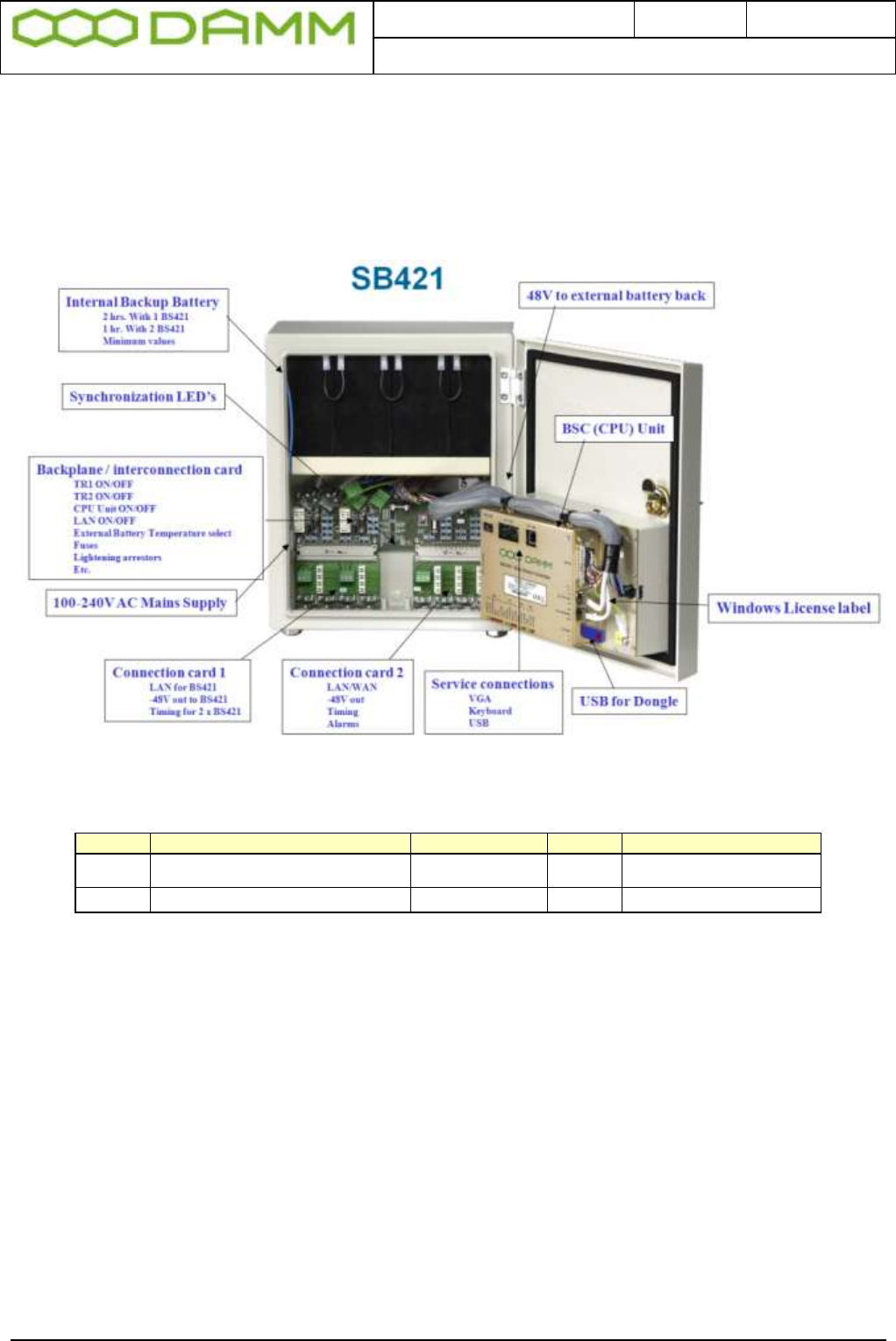
Doc. No.
Rev.
Date
DRAFT
1.01
2012-01-27
Damm Cellular Systems A/S, Denmark
TetraFlex® 7.5 Manual - SB421
TetraFlex® 7.5
Manual
1-3
1.1.4 SB421 basic elements
1.1.4.1 SB421 Variants
Item no.
SB421 Description
Processor
RAM
Storage
105102
General performance w/CF
Celeron M
1.0GHz
512Mb
2GB CF
105105
High performance with/CF
P4 Mobile 1.4GHz
1 GB
8GB CF (2+2+4)
Figure 1-1: SB421 Variants
The above specifications are a minimum and may be changed according to availability of
processors and storage media. Any change in specification will be for a superior value.
To update to 8GB CF and 1GB RAM, order an upgrade kit from DAMM
1.1.4.2 Mechanical Lock
Delivery option: System lock or standard lock, both options including 2 keys.
1.1.4.3 Power supply / charger
The power supply / Charger is capable of supplying -48V DC / 6,5A for the transceivers, BSC
and for charging of the internal or external battery pack.
Connection to the BSC1 via TetraOM, it is possible to monitor the Power Supply
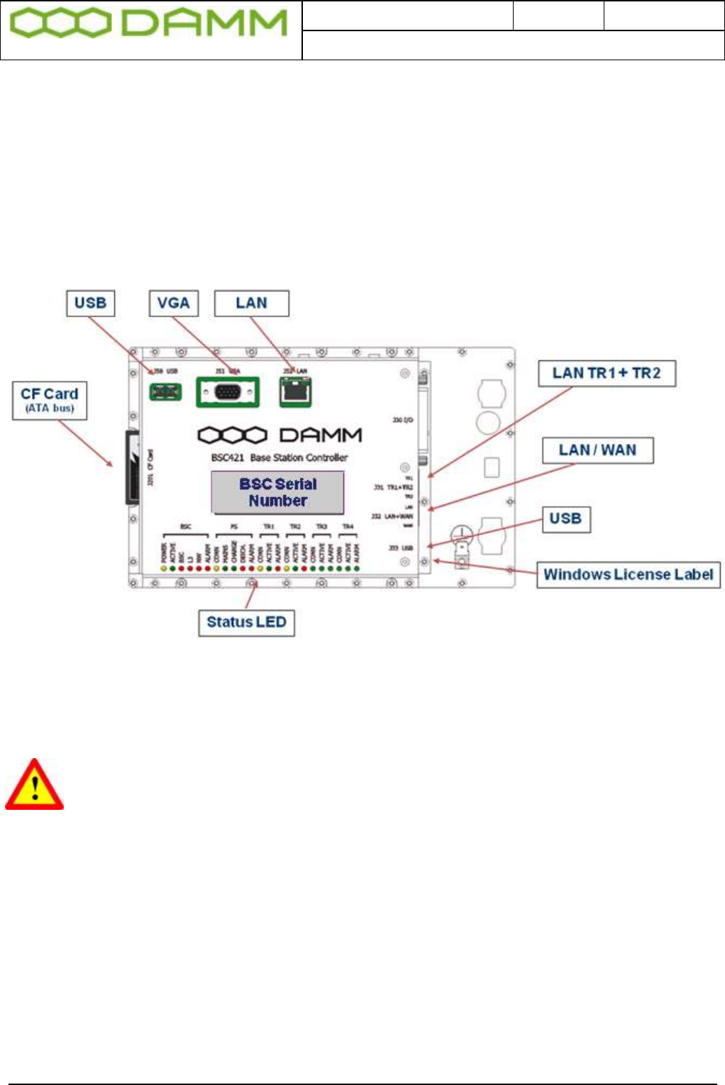
Doc. No.
Rev.
Date
DRAFT
1.01
2012-01-27
Damm Cellular Systems A/S, Denmark
TetraFlex® 7.5 Manual - SB421
TetraFlex® 7.5
Manual
1-4
In OM enter AP <Enter> and the connection is established. Use <F1> for help menu and
select PS421.
.
1.1.4.4 BSC421 Base Station Controller
Please refer to appropriate information in section 1.1.4.1 Regarding the type and specification
of the CPU board (High performance or general performance dependent of the type of
SB421)
Figure 1-2: BSC421
1.1.4.4.1 SB421 Processor board internal backup battery
RISK OF EXPLOSION, IF BATTERY IS REPLACED BY AN INCORRECT TYPE
Dispose of used batteries according to local rules
1.1.4.4.2 Storage unit
Please refer to appropriate specifications in section 1.1.4.1 regarding the type and size of
storage, 8GB Compact flash Card of SB421

Doc. No.
Rev.
Date
DRAFT
1.01
2012-01-27
Damm Cellular Systems A/S, Denmark
TetraFlex® 7.5 Manual - SB421
TetraFlex® 7.5
Manual
1-5
1.1.4.4.3 BSC connections
Connections
o TR1 and TR2 LAN to Interconnection board (J31)
o LAN / Wan to Interconnection board (J32)
o I/O for PS etc. (J30)
o USB1 for Node Dongle (J33)
o USB2 for service and maintenance (J50)
o VGA for service and maintenance (J51)
o LAN for service and maintenance (J52)
o CF socket (J201)
1.1.4.4.4 BSC421 LED’s and Fuses
BSC Status and warning LED’s: All LED’s ON, BSC software is not running
Group
Activity
LED
LED on Means
ALL
All LED’s ON, BSC SW is not running
BSC
POWER
Yellow
Power On
ACTIVE
Green
BSC Active
NETWORK
Red
No Ethernet
BSS
Red
No connection to BSS
BSC
Red
No connection to redundant BSC
ALARM
Red
Other BSC alarm present
PS
LINK
Yellow
Connected to PS
MAINS
Green
Mains present
CHARGE
Green
Battery is charging
DISCH
Red
Battery is discharging
ALARM
Red
PS alarm
TR1
LINK
Yellow
Connection to BS421_1
ACTIVE
Green
BS421 active. (Tetra mode TX on)
ALARM
Red Steady
Blocking alarm
Red Flash
Non-blocking alarm
TR2
LINK
Yellow
Connection to BS421_2
ACTIVE
Green
BS421 active. (Tetra mode TX on)
ALARM
Red Steady
Blocking alarm
Red Flash
Non-blocking alarm
TR3
LINK
Yellow
Connection to BS421_3
ACTIVE
Green
BS421 active. (Tetra mode TX on)
ALARM
Red Steady
Blocking alarm
Red Flash
Non-blocking alarm
TR4
LINK
Yellow
Connection to BS421_4
ACTIVE
Green
BS421 active. (Tetra mode TX on)
ALARM
Red Steady
Blocking alarm
Red Flash
Non-blocking alarm
Figure 1-3: BSC LED's

Doc. No.
Rev.
Date
DRAFT
1.01
2012-01-27
Damm Cellular Systems A/S, Denmark
TetraFlex® 7.5 Manual - SB421
TetraFlex® 7.5
Manual
1-6
Unit
Placement
Fuse Rating
Fuse Size
Interconnection Board
Battery
F101
10A Slow
5x20
BSC421
F102
1A Slow
5x20
TR1
F113
3.15A Slow
5x20
TR2
F133
3.15A Slow
5x20
LAN/WAN Power
F153
1A Slow
5x20
Power Supply
PS421
F101
6.3A Slow
5x20
Figure 1-4: Fuse Listing
1.1.4.5 Interconnection Board
1.1.4.5.1 Connections
o LAN TR1 and TR2 (J31)
o LAN / WAN (J32)
o -48V PS (J22)
o -48V Internal / external battery dependent of plug used (J40)
o TR1 and TR2 connection module (J11)
o LAN / WAN / SEC / Alarm connection module (J12)
1.1.4.5.2 Switches
o TR1 On/Off (SW111)
o TR2 On/Off (SW133)
o LAN/WAN Power On/off (SW131)
o BSC421 On/Off (SW101)
o Temperature sensor internal / external (SW171)

Doc. No.
Rev.
Date
DRAFT
1.01
2012-01-27
Damm Cellular Systems A/S, Denmark
TetraFlex® 7.5 Manual - SB421
TetraFlex® 7.5
Manual
1-7
1.1.4.5.3 LED’s
o EXT SEC IN 2
o EXT SEC IN 1
o TR2 SEC IN
o TR1 SEC IN
Figure 1-5: Interconnection Board
1.1.4.5.4 TR1/TR2 connection module
The TR1/TR2 connection module is located at the LEFT bottom side of the SB421
interconnection board
o -48V DC for TR1 (J1)
o LAN / 1 second synchronization pulse for TR1 (J2)
o -48V DC for TR2 (J3)
o LAN / 1 second synchronization pulse for TR2 (J4)
The TR1 / TR2 connection module is located at the left bottom side of the SB421 housing.
Figure 1-6: TR Connection Module
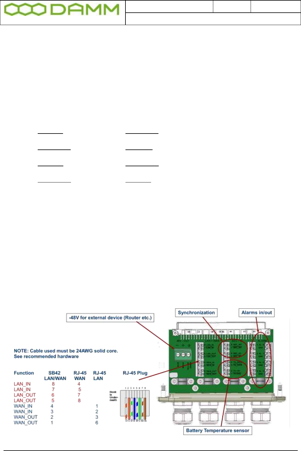
Doc. No.
Rev.
Date
DRAFT
1.01
2012-01-27
Damm Cellular Systems A/S, Denmark
TetraFlex® 7.5 Manual - SB421
TetraFlex® 7.5
Manual
1-8
1.1.4.5.5 PS Connection to TR1 and TR2
o The blue wire of the BS shall be connected to the minus terminal
o The black wire of the BS cable shall be connected to plus terminal.
o The green / yellow wire of the SB421 cable shall be connected to the ground terminal.
1.1.4.5.6 LAN Connection to TR1 and TR2
Connect the following terminals:
NOTE: Cable used must be 24AWG solid core. See recommended hardware
Function SB421 Function BS421 Color
ETH_IN 8 ETH_OUT 1 White / Orange
ETH_IN 7 ETH_OUT 2 Orange
ETH_OUT 6 ETH_IN 3 White / Green
ETH_OUT 5 ETH_IN 4 Green
SEC_IN 4 SEC_OUT 5 Blue
SEC_IN 3 SEC_OUT 6 White / Blue
SEC_OUT 2 SEC_IN 7 White / Brown
SEC_OUT 1 SEC_IN 8 Brown
1.1.4.5.7 LAN/WAN/SEC/Alarm Connection module
The LAN/WAN/SEC/TS/Alarm connection module is located at the inside RIGHT side of the
SB421 interconnection board
1.1.4.5.8 Connections
o -48V DC, 1A out for external units (router, switch etc.) (J5)
o LSA (8 pole) for LAN/WAN (J6)
o LSA (8 pole) for 1 SEC pulse / Temperature Sensor (J7)
o LSA (2x8 pole) for future alarm inputs (8 pairs) (J8A + J8B)
Figure 1-7: LAN/WAN and RJ-45 plug
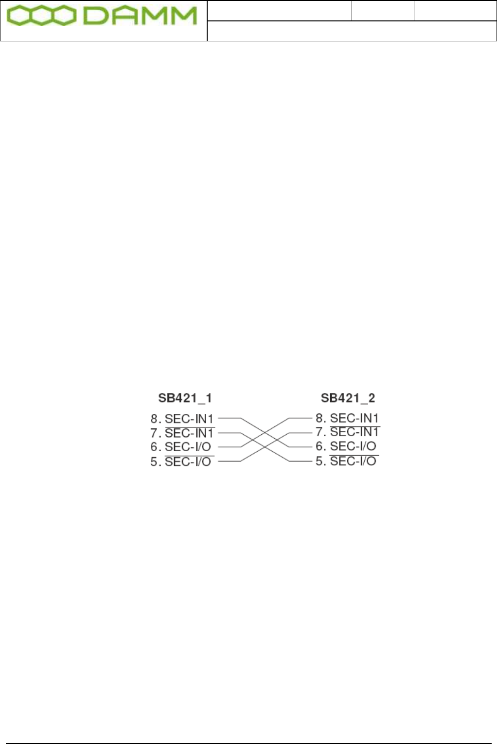
Doc. No.
Rev.
Date
DRAFT
1.01
2012-01-27
Damm Cellular Systems A/S, Denmark
TetraFlex® 7.5 Manual - SB421
TetraFlex® 7.5
Manual
1-9
1.1.4.5.9 Redundant SB421 operation
A second SB421 (BSC) may be configured for redundant operation both as 2 carriers and as
3 - 4 carriers.
Note: A HW modification is needed for redundant and/or 3-4 carrier operation. See section
1.1.5 for further information.
1.1.4.5.9.1 LAN Connection
Note: LAN in / out is used for redundant SB421. If redundant SB421 or multi node backbone
is not used, connect cable to WAN part only. If environment permits, Y-splitter may be used
to separate WAN and LAN, otherwise connect one or two Ethernet cables as desired.
For redundant SB421 (BSC) operation, connect the LAN from each SB421 together.
Connection may be straight trough (auto sense) or crossed cable as preferred.
1.1.4.5.9.2 SEC Connection
In addition to the LAN connection, the SEC connection for synchronization must also be
established.
Figure 1-8: SEC Connections
1.1.4.5.10 Temperature sensor (TS) Connection
Terminals for External Battery Pack Temperature Sensor
For installation, refer to 1.1.4.8 or the instructions delivered with the external battery kit
When used, use SW171 on interconnection board to select internal / external battery
temperature sensor
1.1.4.5.11 Alarm Connection
Future use, not yet defined
1.1.4.6 Mains Connection block

Doc. No.
Rev.
Date
DRAFT
1.01
2012-01-27
Damm Cellular Systems A/S, Denmark
TetraFlex® 7.5 Manual - SB421
TetraFlex® 7.5
Manual
1-10
The 3 screw connection block for the 100-240V AC mains power Phase, Null and Ground is
located on the inner left side of the SB421 housing.
The 100-240V AC mains power connection shall be provided with an
appropriate fuse according to the selected mains supply voltage as to
ensure a consumption of 4,5A (110V) / 2A (230V).
The cables used for the 100-240V AC and -48V DC to the base stations
must be equal to or more than 3 x 1,5mm2
The type of mains cable and fastening of cables must at all times be in
accordance with local rules and specifications.
1.1.4.7 Internal -48 battery assembly (option)
The SB421 is operated at -48V nominal DC (SELV) derived from the internal power supply.
An internal or external battery pack may be connected for backup purposes.
If an internal battery assembly is installed, the battery serial connection wire located at the
top front of the batteries is disconnected at delivery to avoid the battery from being drained.
Please reconnect the wire before use.
Also make sure that the internal/external temperature sensor switch (SW 171 located at the
top right hand corner of the interconnection board) is set to internal.
To ensure stable backup power, it is recommended to check/exchange the battery every 2
years.
1.1.4.8 External -48 battery kit (option) connection block
The 3 screw connection block for -48V DC, 0 and ground is located on the inner right side of
the SB421 housing.
The SB421 is operated at -48V nominal DC (SELV) derived from the internal power supply.
An internal or external battery pack may be connected for backup purposes.
When using an external battery pack, the plus pole of the battery pack shall be grounded with
a 5mm2 yellow/green wire.
Note: In case of using an external battery supply where the plus pole
not is connected to ground then the connection shall include a
disconnection device which disconnects both poles simultaneously,
otherwise there shall be a disconnection device, inserted in the
connection to the minus pole.
The external battery pack consists of a DIN-rail containing a 10A circuit breaker, a 3-pole
terminal strip, a 4-pole modular coupler and the necessary cabling.
The DIN-rail must be mounted as close to the external battery as possible.

Doc. No.
Rev.
Date
DRAFT
1.01
2012-01-27
Damm Cellular Systems A/S, Denmark
TetraFlex® 7.5 Manual - SB421
TetraFlex® 7.5
Manual
1-11
When delivered, the temperature sensor cable is terminated with a 4-pol modular connector.
Please cut the connector and mount the wires in the LSA block of the LAN/WAN connection
module according to this:
SB421 Temperature
J8A Sensor Cable
Pin# Function Color
1 Gnd. Yellow
2 +5V Brown
3 /Data Red
4 Data Blue
Figure 1-9: Temperature sensor connection
Note: If an internal battery kit is mounted, pull out the battery connector J40 for the internal
battery and insert the free connector for the external battery into J40 instead.
If no internal battery kit is present, the external battery plug is inserted from factory.
Note: Please observe polarity of the external battery leads.
Serious damage to the SB421 will occur if not polarized correctly.
Also switch from internal temperature sensor to external temperature sensor using SW 171
on the interconnection board (top right hand corner)
1.1.5 HW change for redundant SB421 / 3 and 4 carrier operation
NOTE: Operation with 3 and/or 4 carriers and/or redundant BSC require a change to the HW
of both SB421 as well as a HW change of carrier 2 and 4 if BS421 HW version is 1. If BS421
HW version is 2, these settings can be made via the TetraOM application. (Please see the
SB421 installation section for further details)
This change is required to ensure correct BSC handover and synchronization of the carriers
A 3/4 carrier system and / or redundant SB421 is marked with a label close to the serial
number label at the outside bottom of the SB421:
REDUNDANT SB 421
3-4 CARRIER SYSTEM
(SYNCHRONIZATION OPTION 2)
The interconnection board on the connector for the BS421 is marked with a label:
SYNCHRONIZATION OPTION 2
when delivered from factory.
If the hardware change is made in the field, i.e. outside DAMM facilities, it must be ensured
that appropriate marking of the SB421 is performed.
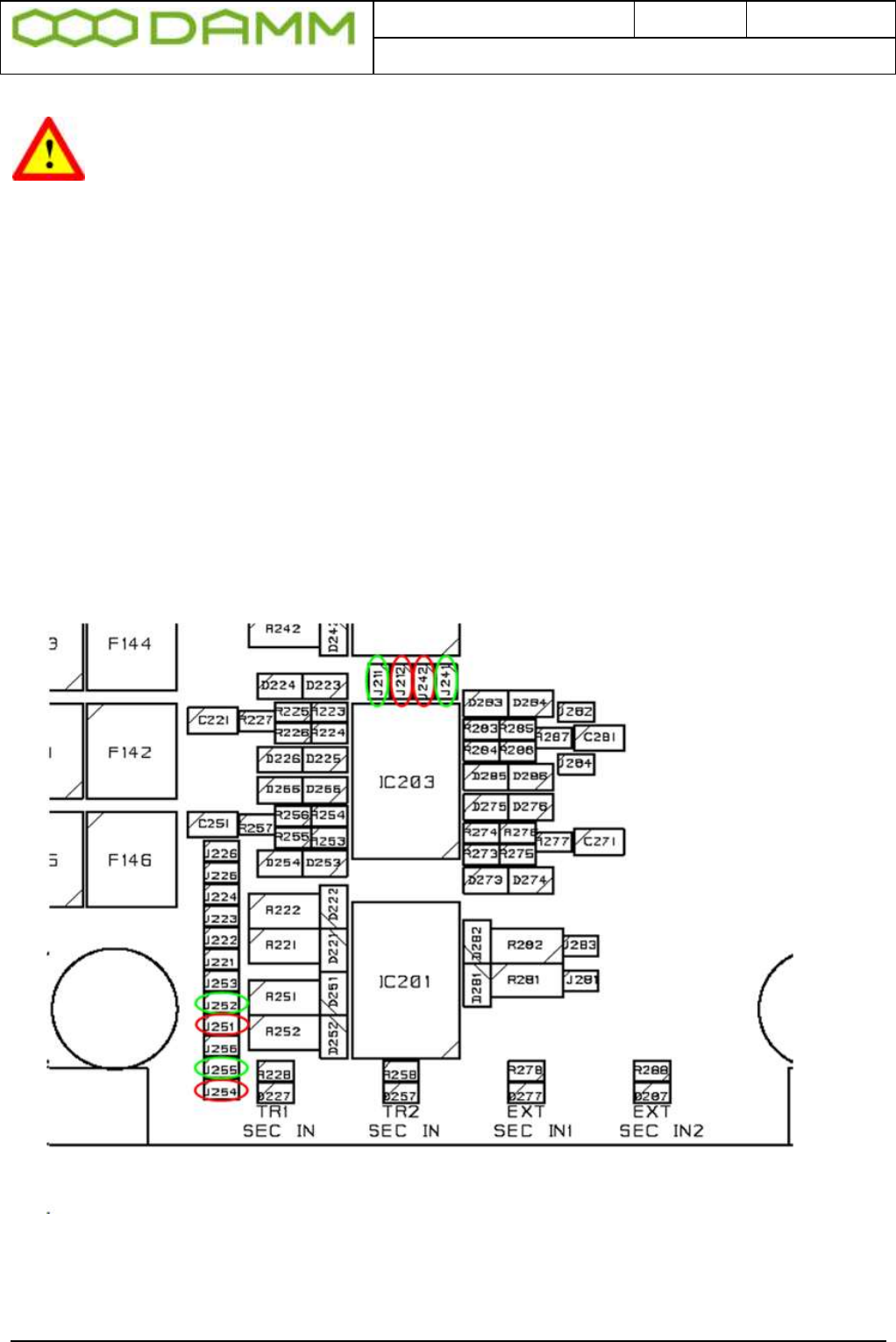
Doc. No.
Rev.
Date
DRAFT
1.01
2012-01-27
Damm Cellular Systems A/S, Denmark
TetraFlex® 7.5 Manual - SB421
TetraFlex® 7.5
Manual
1-12
NOTE: For change in the field, please order a change kit from DAMM. This kit
includes a manual dealing with this issue, jumpers, screws, markings etc. This
change operation includes soldering and unsoldering of SMD components and
should only be done by skilled technicians familiar with SMD handling
The following hardware jumpers need to be changed for correct 3 and 4 carrier or redundant
operation of the SB421:
Normally closed – change to open (marked with green):
J211
J241
J252
J255
Normally open – change to closed (marked with red):
J212
J242
J251
J254
Figure 1-10: Interconnection board jumpers
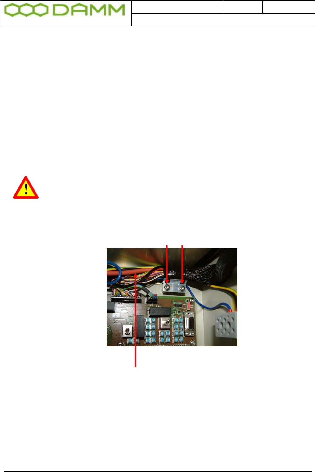
Doc. No.
Rev.
Date
DRAFT
1.01
2012-01-27
Damm Cellular Systems A/S, Denmark
TetraFlex® 7.5 Manual - SB421
TetraFlex® 7.5
Manual
1-13
1.1.6 SB421 Internal Battery Assembly
1.1.6.1 Battery kit maintenance
The battery is specified to a life time of 3-5 years depending on the use and environment.
It is recommended that the battery is checked at least every second year and exchanged if
necessary.
1.1.6.1.1 Installing batteries
1.1.6.1.1.1 Preparation
NOTE: To prevent electrical shock, it is highly recommended to ensure that the
battery terminals are disconnected and properly isolated, either with dummy
terminal shoes or by isolating with thick tape, crimp hose or similar while
removing and/or installing the batteries.
o Place the SB421 on the backside with the door opening facing upward
o Carefully unscrew the two screws holding the door cable assembly
Figure 1-11: Cable assembly
o Move the cable assembly to give access to the 1 nuts holding the ground connection
and the 4 threaded studs for battery base plate mounting
o Carefully remove the nut for grounding. Be careful not to damage the existing cabling
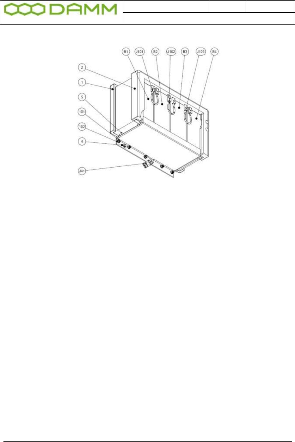
Doc. No.
Rev.
Date
DRAFT
1.01
2012-01-27
Damm Cellular Systems A/S, Denmark
TetraFlex® 7.5 Manual - SB421
TetraFlex® 7.5
Manual
1-14
1.1.6.1.1.2 Installation
Figure 1-12: Internal battery assembly
o Install the “SB421 battery holder Lower” foam (pos.1) in the bottom of the SB421
casing.
o Install the “SB421 battery holder Upper” foam (pos.2) in the front of the SB421 casing
o Attach the blue wire of the battery cable (pos.J41) to the left terminal of a battery
(pos.B1)
o Insert the battery into the battery holder foam and push the battery to the utmost left
position.
o Attach the black wire of the battery cable (pos.J41) to the right terminal of a battery
(pos.B4)
o Insert the battery into the battery holder foam and push the battery to the utmost right
position.
o Insert the two remaining batteries (pos. B2 and B3) into the battery holder foam
between the two already inserted batteries.
o Place the battery holder (pos.4) on the bottom of the batteries in such way that the
threaded studs are fitting the holes of the battery holder. NOTE: Be careful to ensure
the battery cable in placed on the outside of the battery holder.
o Mount and tighten the 5 washers and nuts (pos.101 and 102) and ensure that the
grounding wire is placed under one of the nuts.
o Replace the door cabling assembly using the two screws previously removed.

Doc. No.
Rev.
Date
DRAFT
1.01
2012-01-27
Damm Cellular Systems A/S, Denmark
TetraFlex® 7.5 Manual - SB421
TetraFlex® 7.5
Manual
1-15
J40 Temperature switch
Figure 1-13: Interconnection Module
1.1.7 External -48 battery kit (option) connection block
The 3 screw connection block for -48V DC, 0 and ground is located on the inner right side of
the SB421 housing.
The SB421 is operated at -48V nominal DC (SELV) derived from the internal power supply.
An internal or external battery pack may be connected for backup purposes.
In case of using an external battery pack; the plus pole of the battery pack shall be grounded
with a 5mm2 yellow/green wire.
Note: In case of using an external battery supply where the plus pole
not is connected to ground then the connection shall include a
disconnection device which disconnects both poles simultaneously,
otherwise there shall be a disconnection device, inserted in the
connection to the minus pole.
The external battery pack consists of a DIN-rail containing a 10A circuit breaker, a 3-pol
terminal strip, a 4-pol modular coupler and the necessary cabling.
The DIN-rail must be mounted as close to the external battery as possible.
When delivered, the temperature sensor cable is terminated with a 4-pol modular connector.
Please cut the connector and mount the wires in the LSA block of the LAN/WAN connection
module according to this: SB421 Temperature
J8A Sensor Cable
Pin# Function Color
1 Gnd. Yellow
2 +5V Brown
3 /Data Red
4 Data Blue
Figure 1-14: Temperature sensor

Doc. No.
Rev.
Date
DRAFT
1.01
2012-01-27
Damm Cellular Systems A/S, Denmark
TetraFlex® 7.5 Manual - SB421
TetraFlex® 7.5
Manual
1-16
Note: If an internal battery kit is mounted, pull out the battery connector J40 for the internal
battery and insert the free connector for the external battery into J40 instead.
If no internal battery kit is present, the external battery plug is inserted from factory.
WARNING: Please observe polarity of the external battery leads.
Serious damage to the SB421 WILL occur if not polarized correctly.
Also switch from internal temperature sensor to external temperature sensor using SW 171
on the interconnection board (top right hand corner)
o Unplug the external battery cable from J40
o Insert the internal battery cable plug into J40
o Place the battery temperature sensor switch in the upper position (internal battery)
o Connect the 3 jumper wires (pos.101-103) to the battery terminals.
The battery is now installed and ready for use.

Doc. No.
Rev.
Date
DRAFT
1.01
2012-01-27
Damm Cellular Systems A/S, Denmark
TetraFlex® 7.5 Manual - BS421
TetraFlex® 7.5
Manual
1-17
1.2 BS421
1.2.1 Environmental / climatic requirements
The Base Station is designed for outdoor operation, such that it can be placed in the antenna
mast close to the antennas.
The Base Station is designed to be able to operate at severe environmental conditions.
The Base station is guaranteed to operate under ambient air temperatures from –25°C to
+55°C Celsius. Maximum BS421 cabinet temperature is +85°C. Storage temperature for the
BS421 is from –40°C to +85°C.
Note that the guaranteed MTBF data is valid only within the standard specified temperature
range
Screening of BS421 to specific customer defined temperature range (from -40°C to +55°C
ambient air temperature) is optional upon request.
The Base Station encapsulation complies with IP65
1.2.2 Placement
The recommended placement of the Base Station is as close to the antennas as possible to
reduce cable loss. The placement of the Base Station shall be such that it is securely
fastened to a mast or building that is able to carry the weight of the BS421 and withstand the
local environmental conditions. All cables, antennas etc. shall be properly fastened to the
mast or building using appropriate fixtures as to avoid damage to the equipment and possible
injury to persons.
1.2.3 Grounding
The BS requires careful grounding.
Grounding is important to protect the equipment when inserting/removing cables and to
protect the operator from faulty equipment.
An effective grounding is also important to protect the installation during thunderstorm
(lightning).
The grounding shall be as specified in paragraph 1.2.6 “Power connection to SB421”
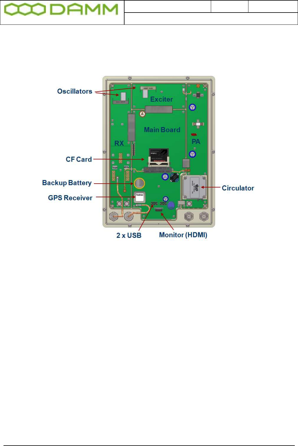
Doc. No.
Rev.
Date
DRAFT
1.01
2012-01-27
Damm Cellular Systems A/S, Denmark
TetraFlex® 7.5 Manual - BS421
TetraFlex® 7.5
Manual
1-18
1.2.4 BS421 main components
Filter cover and filters removed. BS viewed from the filter (back) side
Figure 1-15: BS421 main components
The HDMI monitor connector together with the USB connector allows a connection of a
standard monitor and mouse/keyboard connection
If monitor, keyboard and mouse are connected, the WindowsCE operation system in the
BS421 can be accessed directly for configuration or fault finding purposes
To access the connectors, remove the filter cover
To access the CF card also remove the filter mounting plate
The connectors need not to be unscrewed, just carefully lift the filter base plate slightly and
the CF card can be removed / inserted
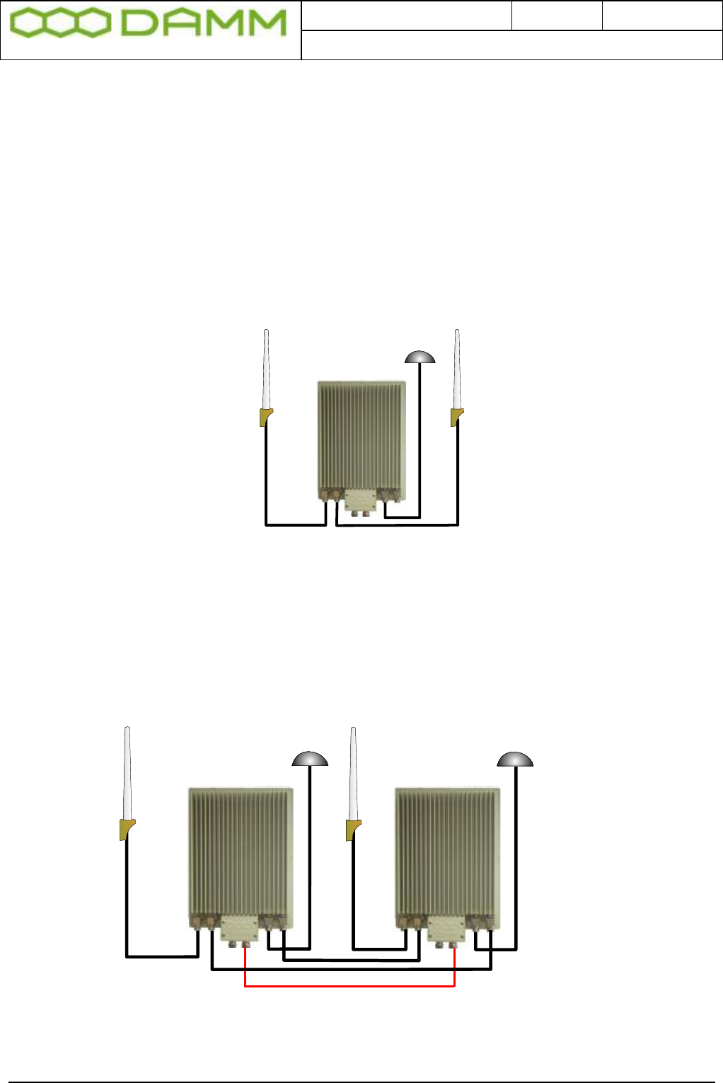
Doc. No.
Rev.
Date
DRAFT
1.01
2012-01-27
Damm Cellular Systems A/S, Denmark
TetraFlex® 7.5 Manual - BS421
TetraFlex® 7.5
Manual
1-19
1.2.5 Attaching RX/TX antennas
Before installing the Base Station please read the application note in this manual about the
Antenna Systems.
The following antenna cables shall be attached:
1.2.5.1 Single Carrier BS installation recommendation (1 x BS421)
o 3 cables to the BS412 (one for RX, one for TX, and one for GPS)
TX/RX-A GPS RX-B
Figure 1-16: Single carrier
NOTE: THE BS421 WILL FUNCTION WITH ONE RX/TX AND WITHOUT GPS ANTENNA WITH THE FOLLOWING LIMITATIONS.
Timing via GPS will not be available (BS421 runs on internal oscillator. Not recommended)
Receiver diversity will not be available
1.2.5.2 Dual Carrier BS installation recommendation (2 x BS421)
o Cables to the 2 x BS421 (two for TX/RX, two for GPS and two for RX-B / A-OUT
between the BS421’s)
Optional
BS1 BS2
TX/RX-A GPS TX/ GPS
RX-A
RX-B RXA-OUT
Figure 1-17: Dual carrier
NOTE: The shown cable (red) is part of the LAN cable and is connected through the SB421.
Cable is shown for system overview only.
NOTE: 2 x BS421 with 2 GPS antennas will provide full GPS redundancy
(Antenna and GPS receiver)

Doc. No.
Rev.
Date
DRAFT
1.01
2012-01-27
Damm Cellular Systems A/S, Denmark
TetraFlex® 7.5 Manual - BS421
TetraFlex® 7.5
Manual
1-20
1.2.6 Power connection to SB421
Before starting on this task, please read the entire chapter carefully.
LAN / 1sec
Figure 1-18: Power connection
The BS421 is operated at -48V nominal DC SELV (Safety Extra Low Voltage). The provision
of power is done via the SB421 TR1/TR2 connection module. See the SB421 installation
section for information on the connection pin out for SB421.
DO NOT UNDER ANY CIRCUMSTANCES USE A POWER SUPPLY THAT HAS
THE MINUS CONNECTED TO POWER SUPPLY CHASSIS
The cables used for power supply must be equal to or more than 3 x 1,5mm2
Connect the three wires in the power connection cable according to the color markings inside
the BS421 system connector.
GND
0 V
- 48V
RX/TX A RXB PS LAN GPS OUT A
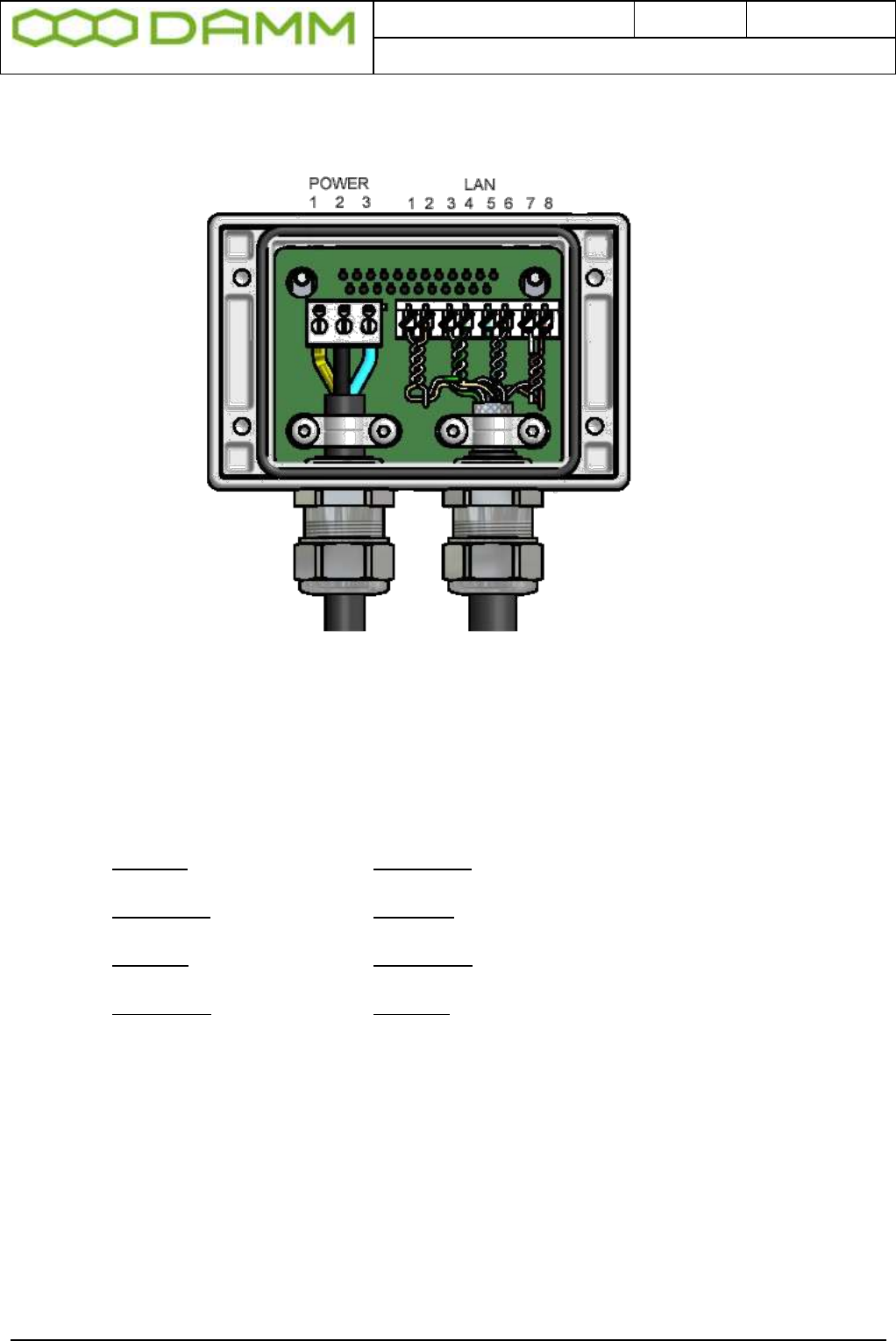
Doc. No.
Rev.
Date
DRAFT
1.01
2012-01-27
Damm Cellular Systems A/S, Denmark
TetraFlex® 7.5 Manual - BS421
TetraFlex® 7.5
Manual
1-21
1.2.6.1 System Connector
Use a LSA tool for the Ethernet connection
Figure 1-19: System Connector
Connect the following terminals:
NOTE: Cable used must be 0.4mm2 to 0.6mm2 (24AWG) solid cores
Function SB421 Function BS421 Color
ETH_IN 8 ETH_OUT 1 White / Orange
ETH_IN 7 ETH_OUT 2 Orange
ETH_OUT 6 ETH_IN 3 White / Green
ETH_OUT 5 ETH_IN 4 Green
SEC_IN 4 SEC_OUT 5 Blue
SEC_IN 3 SEC_OUT 6 White / Blue
SEC_OUT 2 SEC_IN 7 White / Brown
SEC_OUT 1 SEC_IN 8 Brown
POWER:
NOTE: Cable used must be equal to or more than 3 x 1,5mm2 (e.g. DAMM no. 883013)
Ground GND 1 Yellow/Green
0 + 2 Black
-48Volt - 3 Blue
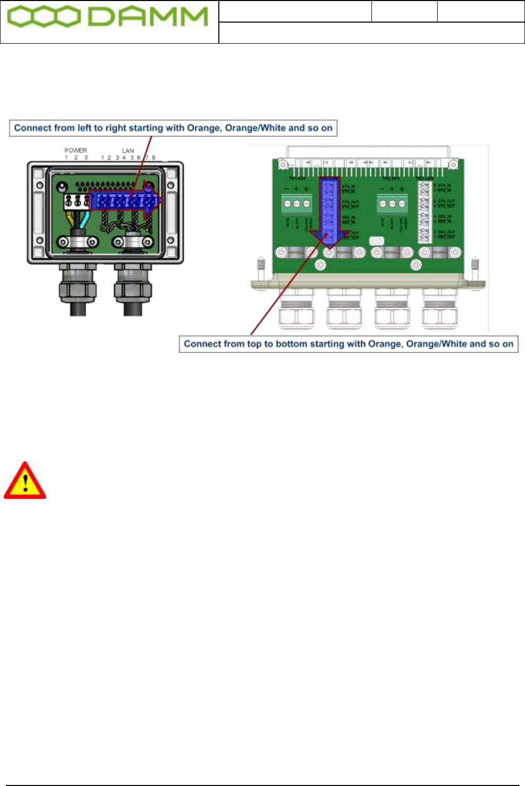
Doc. No.
Rev.
Date
DRAFT
1.01
2012-01-27
Damm Cellular Systems A/S, Denmark
TetraFlex® 7.5 Manual - BS421
TetraFlex® 7.5
Manual
1-22
1.2.6.1.1 Easy connection scheme
See the SB421 installation manual for further details,
1.2.7 BS421 internal backup battery
RISK OF EXPLOSION, IF BATTERY IS REPLACED BY AN INCORRECT TYPE
Dispose of used batteries according to local rules
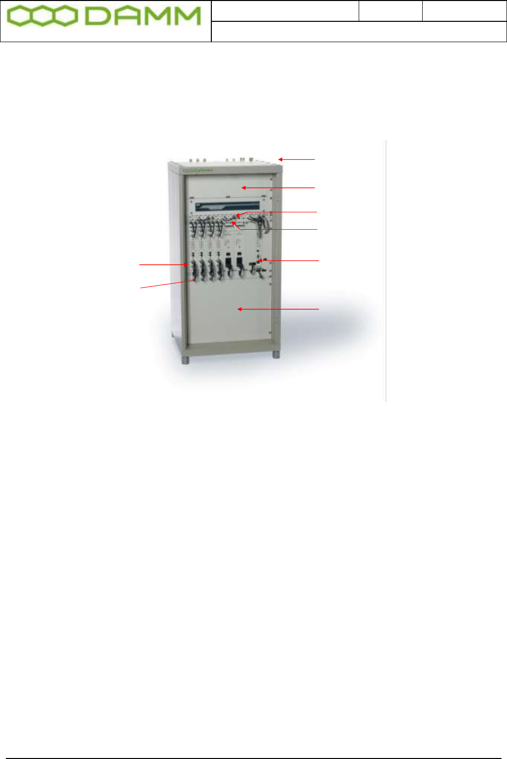
Doc. No.
Rev.
Date
DRAFT
1.01
2012-01-27
Damm Cellular Systems A/S, Denmark
TetraFlex® 7.5 Manual - BS41x
TetraFlex® 7.5
Manual
1-23
1.3 BS41X
BS 414
Coaxial connectors
Connection box CB
Antenna Interface AI
Receiver Multicoupler divider RMD
Base station controller BSC412
4-channel cavity combiner TC
Channel units TR412
RFTL combiner
1.3.1 Environmental/climatic requirements
The Base Station is designed to be able to operate at severe environmental conditions. It is
however recommended to install the BS in rooms with controlled environmental conditions in
order to optimize its reliability and lifetime.
It is important, that the room is free of dust. Condensing humidity is not allowed.
The Base station is guaranteed to operate from –20°C to +55°C.
Note that the guaranteed MTBF data is valid only within the standard specified temperature
range
The BS41x encapsulation complies with IP20
1.3.2 Placement
The Base station shall be placed on a solid floor. It can be either free standing or standing
with the rear against a wall. For normal service rear access to the BS is not needed.
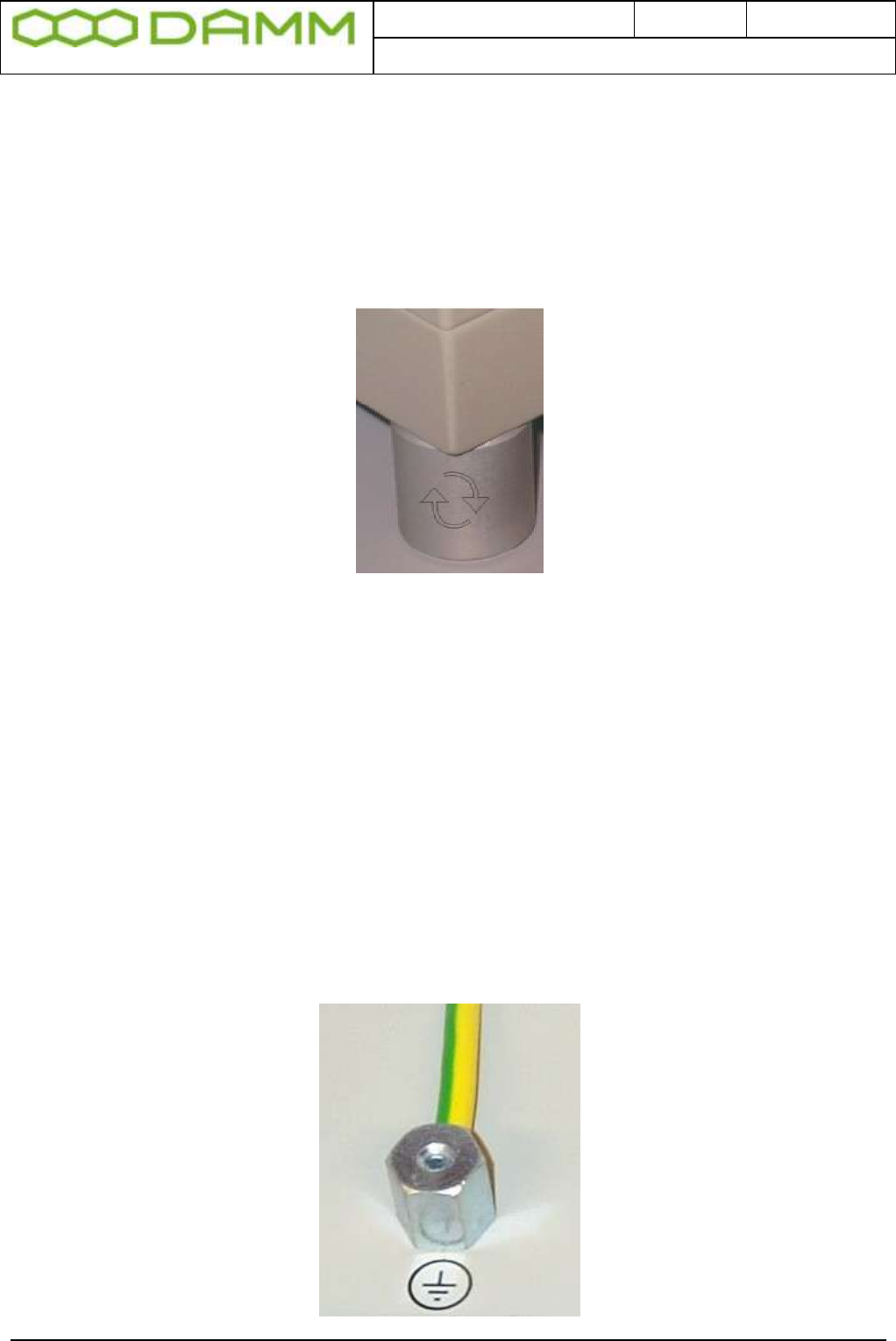
Doc. No.
Rev.
Date
DRAFT
1.01
2012-01-27
Damm Cellular Systems A/S, Denmark
TetraFlex® 7.5 Manual - BS41x
TetraFlex® 7.5
Manual
1-24
After placement the four legs under the BS can be adjusted for accurate vertical position to
compensate for an uneven floor.
In areas with the possibility of earthquakes, it is recommended that the BS be secured to the
floor with bolts. Access to the base may require removal of the lowest TX combiner in the
rack.
Figure 1-20: Level adjustment
1.3.3 Grounding
The BS requires careful grounding. For temporary operation, the mains earth connection can
be used. For permanent installations an effective ground shall be established and connected
to the grounding screw on the rear right top of the BS with a 15sq. mm yellow/green wire.
Grounding is important to protect the equipment when inserting/removing cables and to
protect the operator from faulty equipment.
An effective grounding is also important to protect the installation during thunderstorm
(lightning).
Figure 1-21: Grounding
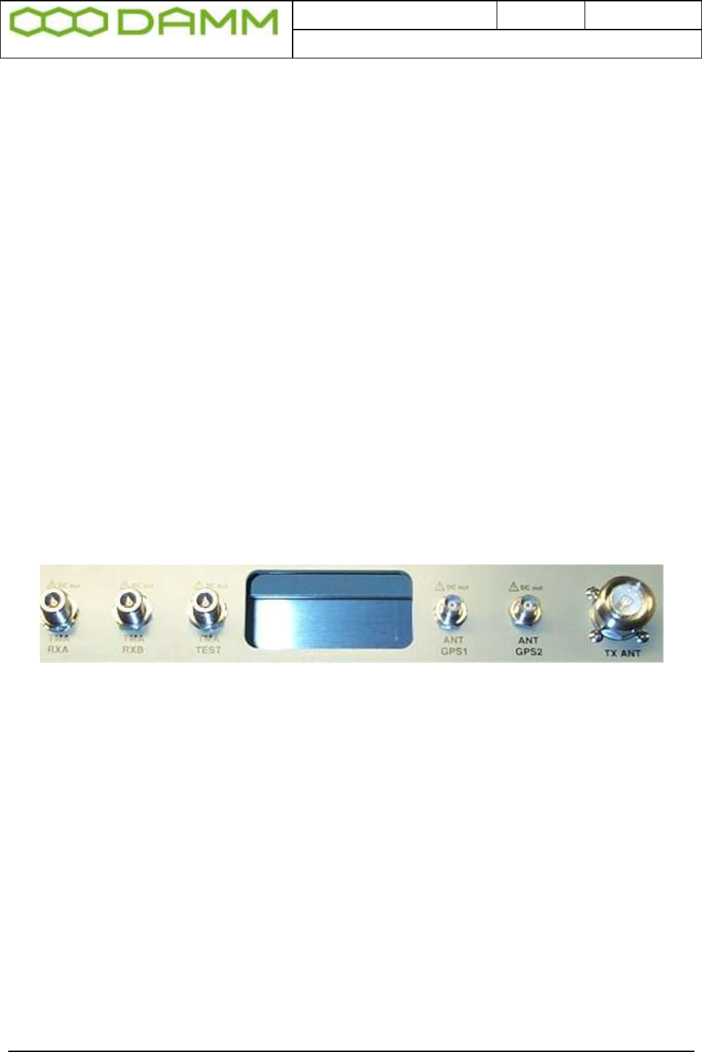
Doc. No.
Rev.
Date
DRAFT
1.01
2012-01-27
Damm Cellular Systems A/S, Denmark
TetraFlex® 7.5 Manual - BS41x
TetraFlex® 7.5
Manual
1-25
1.3.4 Attaching antennas
Before installing the Base Station please read the application note in this manual about the
Antenna Systems.
The following antenna cables shall be attached:
If the jumper between ANTA and RSOUT is NOT connected (Separate RXA, RXB and TX
antennas)
o 3 cables to the TMD412 (two RXA and RXB and one for Test)
o 1 cable to the TX antenna
o 1 or 2 cables to the GPS antennas
When a jumper coaxial wire is connected between ANTA and RXOUT on the TMD.
o 3 cables to the TMD412 (one RXA/TX, one RXB and one for Test)
o 1 or 2 cables to the GPS antennas
Figure 1-22: Antenna connectors
1.3.5 Connection to Battery
Before starting on this point please read the section 1.3.8.3 in this manual about Battery
attachment.
The BS may be connected to a 48V battery, which the BS can charge.
The Base Station is prepared for –60V battery operation, wherefore a switch is placed on the
back plane of the BS to indicate to the PS411’s, whether a –48V or –60V battery is used.
Note that the present version of PS411 can only operate with –48V DC, wherefore this
feature is not active, and the switch shall be placed in the –48V position.
The Switch is accessible by removing the PS411 Power Supplies.
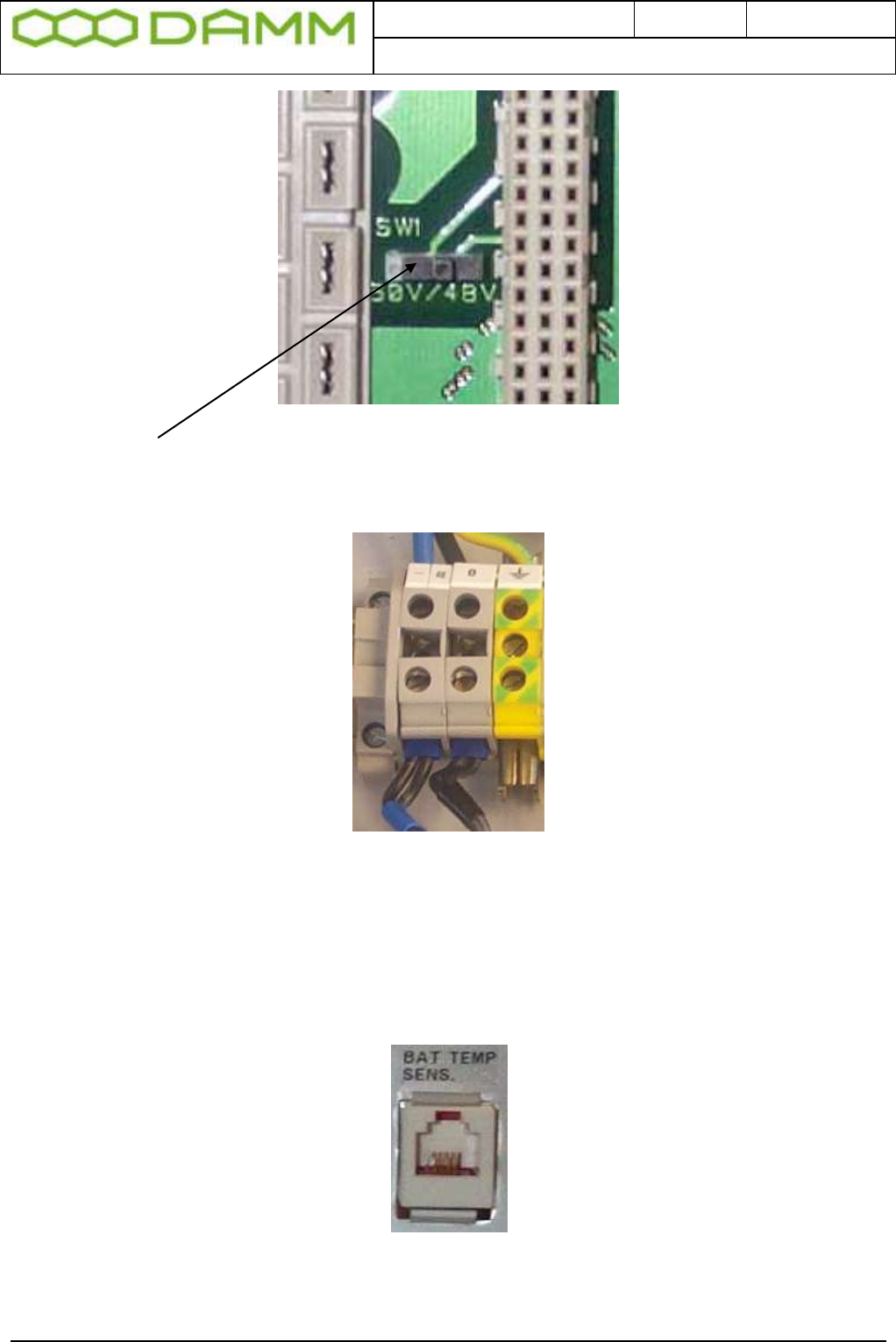
Doc. No.
Rev.
Date
DRAFT
1.01
2012-01-27
Damm Cellular Systems A/S, Denmark
TetraFlex® 7.5 Manual - BS41x
TetraFlex® 7.5
Manual
1-26
Figure 1-23: Power selection
Left position = 60V, Right position = 48V
The external battery shall be connected in the connection box in top of the BS. Minimum
recommended cables dimension is 10mm2 with black for plus (ground) and blue for minus.
Figure 1-24: Power terminals
The battery connection shall be provided with a circuit breaker close to the battery to protect
against over-current at short circuits in the connection cable or internal in the Base Station.
If the BS shall charge the battery, the TS411 Temperature Sensor shall be placed at the
battery and connected to the BS in the connection box.
Figure 1-25: Temperature sensor connection
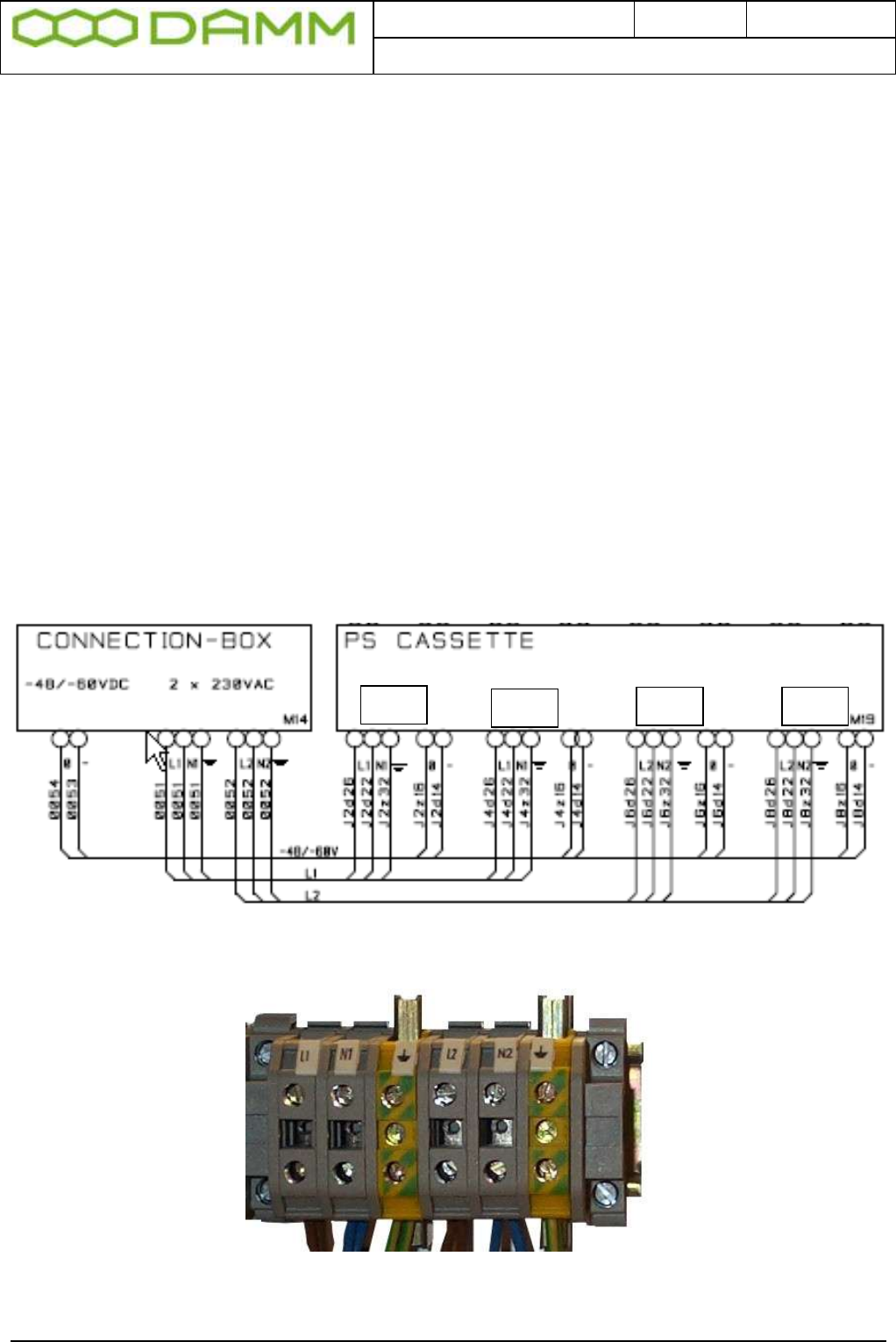
Doc. No.
Rev.
Date
DRAFT
1.01
2012-01-27
Damm Cellular Systems A/S, Denmark
TetraFlex® 7.5 Manual - BS41x
TetraFlex® 7.5
Manual
1-27
The plus pole of the Battery shall be grounded with a 15mm2 yellow/green wire. A protective
ground connection shall also be established from the Battery to the BS.
Note: In case of using a DC mains supply where the plus pole not is connected to ground
then the connection to the DC mains supply shall include a disconnection device which
disconnects both poles simultaneously, otherwise there shall be a disconnection device, in
the connection to the minus pole.
1.3.6 Connection to AC Mains
The BS is provided with Power Supplies supporting direct connections to 100V-240V AC and
47-63 Hz, one phase. Mains connection shall not be established, when the BS is running on
an external battery with separate charger.
Mains are connected in the connection box (See 1.3.7). Two separate connections are
available and both shall be connected. The first (and third) PS411 is powered from the left
connection and the second (and fourth) PS411 from the right connection. The split makes it
possible to run the BS on two different mains phases to obtain redundancy in case of a phase
dropout (fuse blown). The two connections can also be parallel connected in the BS.
The mains connection is provided with a protective earth connection. If a separate earth
connection is provided on the BS, it is recommend to leave it open.
Figure 1-26: Mains connection block
PS1
PS3
PS2
PS4

Doc. No.
Rev.
Date
DRAFT
1.01
2012-01-27
Damm Cellular Systems A/S, Denmark
TetraFlex® 7.5 Manual - BS41x
TetraFlex® 7.5
Manual
1-28
Note: Each of the installed power supplies are individually connected to the AC mains
therefore in order to disconnect the Base Station from AC mains, the AC switch of all installed
power supplies shall be switched to off.
Note: It is recommended that the main power installation includes short circuit back
protection which reacts in case of the current is exceeding 16A.
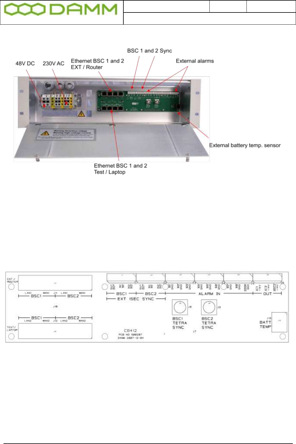
Doc. No.
Rev.
Date
DRAFT
1.01
2012-01-27
Damm Cellular Systems A/S, Denmark
TetraFlex® 7.5 Manual - BS41x
TetraFlex® 7.5
Manual
1-29
1.3.7 Connection Box CB412
Figure 1-27: Connection box
1.3.7.1 Ethernet connect
8 Ethernet connections are present for BSC1 and BSC2:
BSC1 LAN1 and 2 and BSC 2 LAN1 and 2 for connection to other nodes, routers, log server,
Network Management etc..
BSC1 WAN1 and 2 and BSC2 WAN1 and 2 for connection to corporate network, SIP units,
Remote desktop, Switch board (PABX), API etc.
Figure 1-28: CB412 connection board
The connection from BSC1 and BSC2 is coming from the LAN and WAN connector on the
front of the BSC412 front plate and connected on the backside of the connection box and
spitted out to LAN1 / LAN2 and WAN1 / WAN2.
NB: When using 2 BSC412’s there is a connection between the BSC1 and BSC2 LAN and
WAN on the backplane connection, this will be switched off by an electronic switch device
when there is a cable in both BSC1 LAN1 and BSC2 LAN1 and the same goes for the WAN
connector. This is to avoid recirculation of the signals
See also section 2.7.3 for Ethernet software configurations description.

Doc. No.
Rev.
Date
DRAFT
1.01
2012-01-27
Damm Cellular Systems A/S, Denmark
TetraFlex® 7.5 Manual - BS41x
TetraFlex® 7.5
Manual
1-30
1.3.7.2 External alarm connections
The BS is provided with 8 external alarm inputs. One of these is reserved for the “Door Open”
alarm (Not yet implemented) and the rest are currently not pre-defined for a specific function.
All alarm inputs are provided with a 1Kohm resistor to +5V. To activate an alarm the input
shall be grounded.
The BS is also provided with 3 alarm outputs currently not allocated any specific function.
The outputs are open collector outputs capable of sinking 0.25A. The outputs are protected
for inductive transients with 36V zener diodes.
The alarm connections are provided with LSA-type connections, accepting solid wires with
the dimension 0.4mm2 to 0.6 mm2.
1.3.8 Back-up battery for BS41x
1.3.8.1 Introduction
This application note describes how to attach a backup battery to the BS41x Tetra Base
Stations.
All the BS41x versions are powered with one or several PS411 Power Supplies.
The PS411 can be powered directly from an external DC source of –48V.
The PS411 can also be powered directly from AC mains of 100 to 240V, 47-63Hz without any
battery backup. This mode is convenient at test of the Base Station.
The standard installations, however, is the combination of AC mains power feed with a –48V
lead-acid backup battery connected. The PS411 has all the build-in features to have the
battery connected and charge it. This allows uninterrupted service for a period depending on
the size of the battery. For very service-critical systems this can be extended with a Diesel
generator starting automatically after a certain period of battery operation.
All BS versions can be connected to an external –48V lead-acid battery. The external battery
kit includes a circuit breaker to protect the battery and the TS411 temperature sensor to allow
the PS411 to provide a temperature compensated charging voltage.
1.3.8.2 Selecting external batteries
Several issues should be taken into account, when selecting batteries. In general, only
battery types intended for use as back-up battery in telecom systems should be used.
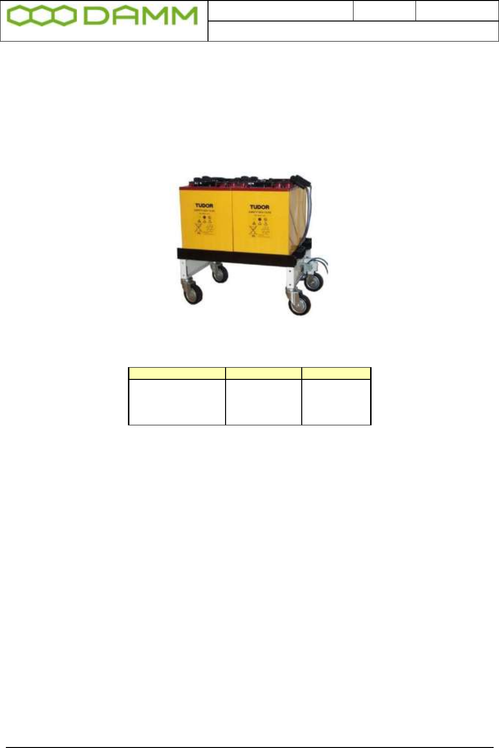
Doc. No.
Rev.
Date
DRAFT
1.01
2012-01-27
Damm Cellular Systems A/S, Denmark
TetraFlex® 7.5 Manual - BS41x
TetraFlex® 7.5
Manual
1-31
The battery lifetime is a critical parameter. High quality back-up batteries normally have a
specified lifetime of 10-15 years at normal room temperature.
The batteries should also be of the gas-tight type when co-located with the BS to avoid
corrosive gases, which may damage the electronics.
A battery capacity of 48V 50Ah would be a typical choice for a 4-carrier BS. The picture
below shows an example of such a battery.
The following estimated back-up times is being achieved with a 50Ah battery (weight about
130kg):
Note that for higher load current the efficiency of the battery drops considerably below the
100%.
For the 8-carrier Base Station a 100Ah battery could be considered (weight about 250kg).
1.3.8.3 External battery installation
The connections needed for the battery attachment is shown on the schematics below
Base Station size
Current
Backup time
2-carrier
6A
8 hours
4-carrier
11A
4 hours
6-carrier
16A
2.5 hours
8-carrier
21A
1.8 hours

Doc. No.
Rev.
Date
DRAFT
1.01
2012-01-27
Damm Cellular Systems A/S, Denmark
TetraFlex® 7.5 Manual - BS41x
TetraFlex® 7.5
Manual
1-32
BS
Sensor
-
+
GND
Battery
48V
-
+
4-Wire
Blue 10sqmm
Black 10sqmm
Yellow/Green 15sqmm
Circuit
Breaker 50A
Sensor
The minus pole of the battery shall be provided with a circuit breaker as close to the battery
as possible in order to protect for any excess current flow at a short circuit. The nominal
current shall be higher than the peak charging/discharging current to avoid unintended
disconnects.
The Base Station should be connected to the battery with 10 mm2 blue and black wires. In
addition, a 15mm2 yellow/green wire shall connect protective ground on the rack to ground on
the battery, which should be connected to the plus-pole of the battery. The Base Station itself
(and optionally the battery) shall be provided with an effective grounding.
The TS411 temperature sensor shall be located at the battery and connected to the BS in the
connection box with the delivered 10m of cable. The cable is a standard 4-wire telephone
cable provided with two 4-pole RJ11 plugs (narrow types). The cable can be extended if
needed.
1.3.8.4 Battery charging
The PS411 contains configuration settings to control the charging of a –48V battery.
If charging is not selected the PS411 gives a fixed output voltage of –48V DC.
If charging is selected and the TS411 is properly attached, the PS411 changes to charging
mode. The output voltage is then increased to the correct charging voltage selected with the
configuration settings normally controlled from the BSC.
The output voltage is calculated from the nominal charging voltage at 25 Celsius, e.g. 2.25V
DC per cell and the required temperature compensation, e.g. –72mV per Celsius. With these
values the voltages would be:
Temperature
V-charge
-20 Celsius
57.2V
+25 Celsius
54.0V
+55 Celsius
51.8V

Doc. No.
Rev.
Date
DRAFT
1.01
2012-01-27
Damm Cellular Systems A/S, Denmark
TetraFlex® 7.5 Manual - BS41x
TetraFlex® 7.5
Manual
1-33
1.3.8.5 Battery deep discharge protect
The Base Station is provided with a feature to switch off the load, when the battery is close to
being discharged in order to protect the battery.
The Base Station is prepared for –60V battery operation, wherefore a switch is placed on the
back plane of the BS to indicate to the PS411’s, whether a -48V or -60V battery is used.
Note that the present version of PS411 can only operate with -48V DC, wherefore this feature
is not active, and the switch shall be placed in the –48V position.
Battery
48V
Turn-on voltage
45.0V
Turn-off voltage
40.0V

Doc. No.
Rev.
Date
DRAFT
1.01
2012-01-27
Damm Cellular Systems A/S, Denmark
TetraFlex® 7.5 Manual - Basic system parameters
TetraFlex® 7.5
Manual
2-34
PART-2: SW Installation and
Configuration

Doc. No.
Rev.
Date
DRAFT
1.01
2012-01-27
Damm Cellular Systems A/S, Denmark
TetraFlex® 7.5 Manual - Basic system parameters
TetraFlex® 7.5
Manual
2-35
2.1 BASIC SYSTEM PARAMETERS
TetraFlex® 7.5 software is not compatible with earlier versions, and nodes with e.g. version
7.4 can not interact with nodes with version 7.5.
Please consult the document “Update guideline for ver.7.4 to 7.5” for upgrading to TetraFlex
7.5.
2.1.1 System capability
The System is preconfigured with the full TetraFlex® SW package, but some functions may
be restricted by the dongle setting.
The following is the compiled default software parameters of the system, but they can be
increased on request. Some of the functions are dongle related. Readout can be done with
TetraOM command. The system can be ordered as “Standard” and “Optional Enhanced”
system size.
Function
Standard
Optional Enh.
Dongle
Organizations
1.000
1.000
No
Profiles
2.000
10.000
No
Subscribers max.
20.000
150.000
No
Nodes max.
254
999
Yes
Voice GW connection max.
32
32
Yes
Application GW connections max.
20
20
Yes
Application GW Streams max.
100
100
Yes
Application GW Streams/Application max.
32
32
Yes
Numbers of Log servers max.
25
100
Yes
You can check these parameters with OM command: S00/C

Doc. No.
Rev.
Date
DRAFT
1.01
2012-01-27
Damm Cellular Systems A/S, Denmark
TetraFlex® 7.5 Manual - Virus protection
TetraFlex® 7.5
Manual
2-36
2.2 VIRUS PROTECTION
2.2.1 Introduction
The DAMM system is designed with the LAN area as a completely closed IP area without any
connection to the outside world.
That means, that BSC’s, TR’s etc. without a WAN connection cannot access the outside
world and cannot be accessed from the outside world.
Only system components with a WAN connection have a risk to get infected, including
Gateways, Log Servers, Terminal Servers etc., all entities, which if present need external
access.
Any virus problem on systems have been closely watched for a period of time, but so far no
infections have been observed.
Regarding system components WITHOUT a WAN connection, it is most safe to proceed
without any virus protection as we do today. This is of cause under the presumptions that the
operator has control with external media as USB sticks, CD etc. These media must be virus
free before inserted or connected to the system. Installing a virus protection would create the
need of opening up access to an update server, which would increase the risk that viruses
could penetrate into the internal LAN area.
2.2.2 Virus Threat
The major threat for a system is that viruses will infect the system components with WAN
access. These components will either be a Damm BSC running Windows or a PC with a full
Windows installation. The major source of infection is normally via E-mails and via Home
pages. It is therefore strongly recommended never to use any computer in a system for these
tasks.
2.2.2.1 Standard PC
For standard PC’s running Windows and used for tetra applications or running a BSC the
firewall can be kept activated. It is just needed to include the programs in the exception list.
Window XP SP3 and Windows 7 ask automatically, whether you want to do that. In addition,
it is recommended to have an anti-virus program running on these computers. Internally at
DAMM, AVG antivirus is used and can be recommended. This gives a reasonable protection,
and no issues have been seen regarding conflicts between AVG and Tetra applications. The
Log Server (TetraFlex® only) could have some performance degradation during scanning,
whereas the BSC is running with higher priority and is not expected to be degraded.
Scanning should be setup to run in the night when system activity is low. No experience has
been gained with other anti-virus programs.

Doc. No.
Rev.
Date
DRAFT
1.01
2012-01-27
Damm Cellular Systems A/S, Denmark
TetraFlex® 7.5 Manual - Virus protection
TetraFlex® 7.5
Manual
2-37
2.2.2.2 BSC
Regarding the DAMM BSC’s running Windows Embedded the risk of infection is much lower
as a lot of the services giving problems are not installed here, although the risk of infection
still exists. Attempts have earlier been made to get AVG installed, but AVG does not accept
the product code of Windows Embedded, and DAMM has not succeeded to get AVG to
implement the needed changes.
2.2.3 MS Security Essentials
Microsoft has recently released their new Microsoft Security Essentials. At present this is not
compatible with the BSC.
In case installation has been attempted, an error message
DATA ENCRYPTION detected an error in the protocol stream and has disconnected
the client may appear when attempt is made to connect via the remote desktop
To correct this, refer to the following Microsoft KB article
http://support.microsoft.com/kb/323497

Doc. No.
Rev.
Date
DRAFT
1.01
2012-01-27
Damm Cellular Systems A/S, Denmark
TetraFlex® 7.5 Manual - Dongle Configuration
TetraFlex® 7.5
Manual
2-38
2.3 DONGLE CONFIGURATION
2.3.1 License Dongles
2.3.1.1 Site versus Node:
Until the DAMM TetraFlex® system software was introduced the word “Site” has been used to
indicate number of Radio Sites in a system. There was coherency between number of “Sites”
and number of “Radio sites”.
The DAMM TetraFlex® concept opens for “Sites” that is not a “Radio site” but a “Gateway
site”, a “NM site” or a “Log Server site”, and that one physical “Site” can be both a “Radio
site” but also a “Gateway site”.
Therefore “Node” is introduced.
A node is consequently:
Any PC running BSC.exe software, except for a redundant BSC
A site is consequently:
The geographical position of nodes or equipment
2.3.1.2 Dongle types
NOTE: TetraFlex® V7.20 and forward require a new type of dongle. If no encryption key is
required in the dongle, it is possible to order a number of empty spare dongles and remotely
upgrade these as needed. If encryption key is required and dongle is to be used at the node
containing the master subscriber register, the dongle must be ordered from DAMM sales.
Currently there are 5 types of dongles:
o Node license dongle
Including possible settings for Node, API, Packet Data, Voice GW and Log
Server
o API client dongle
o Dispatcher dongle
o Log Server/ log client dongle
o Spare dongle
All dongles are programmed with:
o Dongle hardware serial number.
o DAMM dongle serial number.
A Node dongle is programmed with:
o Application Date Limit.
o Dongle Date Limit. (This is intended for demo system and special projects only and
will as default be set to infinity).
o Nodes Max (must be equal to or higher than the highest defined node number)
o Radio Cell TR’s max

Doc. No.
Rev.
Date
DRAFT
1.01
2012-01-27
Damm Cellular Systems A/S, Denmark
TetraFlex® 7.5 Manual - Dongle Configuration
TetraFlex® 7.5
Manual
2-39
o Voice Gateway connections max
o Packet Data Gateway
o Application connections max
o Voice Streams max
o Air Interface Encryption
o Air Interface Encryption KSG
An API Client dongle is programmed with:
o Dongle Date Limit
o Dispatcher, Yes - No
A Log Server dongle is programmed with:
o Dongle Date Limit
o Application Date Limit
o Call Info Log
o SDS content Log
o Voice Log Max
By means of the dongle read out software or the TetraOM commands the End-User can read:
o Dongle hardware serial number
o DAMM dongle serial number
o System and Node license’s settings.
Doc. No.
Rev.
Date
DRAFT
1.01
2012-01-27
Damm Cellular Systems A/S, Denmark
TetraFlex® 7.5 Manual - Dongle Configuration
TetraFlex® 7.5
Manual
2-40
2.3.1.3 Dongle settings and combinations
APPLICATIONS
BSC
A detail for each application has
been defined in the system
planner. Be aware that the
selections here may result in
additional dongle hardware to be
invoiced.
Voice GW
Packet data GW
Application Conn
Log Server
Log Client
API
DAMM Dispatcher
Network Management
DONGLE
BSC node (BSC 4xx)
1st BSC
Redundant BSC node (BSC 4xx)
2nd BSC
BSC node dongle (PC)
API Client Dongle
Log Server dongle
Log client dongle
Network management dongle
Network Management may be
invoked from any PC with a valid
DAMM dongle.
Select only if separate NM dongle
is desired
OBS: Max. 1 selection per
column except for BSC.
Max 4 applications per dongle.
(BSC = 1 application)
Log server statistics only functionality is available if Log Server is installed and a
DAMM dongle is present. Needs no dongle reference to server or client
Dispatcher only refers to DAMM dispatcher, not customer programmed
Figure 2-1: Dongle Combinations
2.3.1.4 Dongle Update
The dongle can be reprogrammed by means of an update file. The file can be sent by e-
mail from DAMM to the Partner, and downloaded locally to the system by means of the
Remote Desktop icon in the node and thereafter executed. The update file is linked to the
Dongle hardware serial number and can only be executed on the node where the specific
dongle serial number is installed. The update file (.exe file) can be placed on any driver on
the target e.g. C:\ or the desktop and executed from there.
The special encryption key cannot be updated. The dongle must be returned to DAMM for
change/update of encryption key, but other parameters may be upgraded remotely.
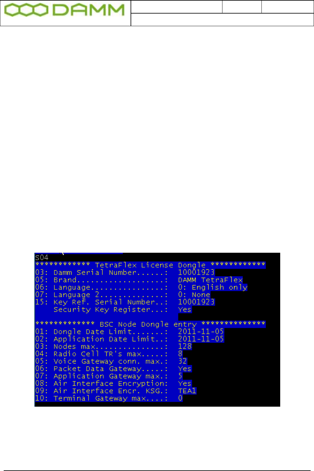
Doc. No.
Rev.
Date
DRAFT
1.01
2012-01-27
Damm Cellular Systems A/S, Denmark
TetraFlex® 7.5 Manual - Dongle Configuration
TetraFlex® 7.5
Manual
2-41
2.3.1.5 Spare part Dongle:
o A Spare Part Dongle will be offered at a nominal price. If used in the node containing
the master subscriber register, the dongle can only be used as spare dongle if the
original dongle has no encryption key programmed. In case that encryption key is
present, the replacement dongle must be ordered from DAMM sales.
o An order for Spare Part Dongles shall follow the Administrative procedure for
ordering.
o A Spare Part Dongle is programmed with all settings at “zero”.
o When needed, the Partner must inform DAMM about the serial number of the faulty /
missing dongle and DAMM will send a mail with a file containing the System and
Node license’s settings from the original dongle.
o An invoice will be issued with the value of the System and Node licenses in the
dongle, which will be credited when the original dongle is received by DAMM
2.3.1.6 Dongle exchange and information of content
At startup the BSC.exe is checking if a dongle is present, and if missing, the BSC will not
start.
To view the preprogrammed BSC settings in the dongle, the following TetraOM commands
may be used:
S04 Shows the license settings of the dongle for the BSC:
Figure 2-2: Dongle Readout
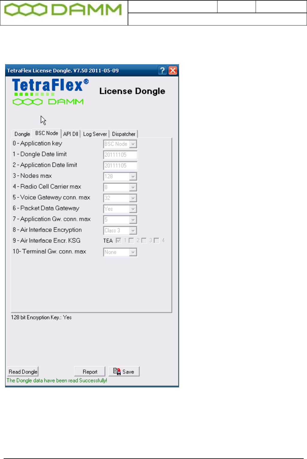
Doc. No.
Rev.
Date
DRAFT
1.01
2012-01-27
Damm Cellular Systems A/S, Denmark
TetraFlex® 7.5 Manual - Dongle Configuration
TetraFlex® 7.5
Manual
2-42
The total numbers of dongle settings can only be shown with the license dongle reader
program that can be found on the “Startmenu” – “Tetraflex” – “Dongle” – “License dongle”:
2.3.1.7 Explanation to the readout:
o DAMM dongle serial number (HW serial number can be red by S04/I)
o Brand, in this case DAMM TetraFlex® (OEM version are available)
o Language
o Key Register: If YES the dongle is programmed with a security key for Authentication
/ Encryption

Doc. No.
Rev.
Date
DRAFT
1.01
2012-01-27
Damm Cellular Systems A/S, Denmark
TetraFlex® 7.5 Manual - Dongle Configuration
TetraFlex® 7.5
Manual
2-43
BSC Node:
o Dongle Date Limit:
If set, the dongle ceases operation when the specified date is reached
o Application Date Limit:
The Application Date in the SW package is compared to this date for SW
update allowance
o Nodes Max:
The maximum node number which can be defined in the system
o Radio Cell TR’s max:
Maximum allowed transceivers per radio cell
o Voice Gateway Conn. max:
Maximum telephone connections per node
o Packet Data Gateway:
Packet data allowed or not
o Application Conn. max:
Maximum application connections (API interfaces)
o Air Interface Encryption:
Encryption allowed or not
o Air Interface Encr. KSG:
The TEA active in the BS (TEA1, TEA2, and TEA3)
o Terminal Gateway max:
(not include in this version)
The next dongle settings are not shown with the S04 command only in the Dongle
reader program:
Log Server:
o Dongle Date Limit:
If set, the dongle ceases operation when the specified date is reached
o Application Date Limit:
The Application Date in the SW package is compared to this date for SW
update allowance
o Call Info Log:
Call information logging set Yes or No
o SDS content Log:
SDS contents logged Yes or No
o Voice Log Max:
Maximum of voice streams that can be logged simultaneously

Doc. No.
Rev.
Date
DRAFT
1.01
2012-01-27
Damm Cellular Systems A/S, Denmark
TetraFlex® 7.5 Manual - Dongle Configuration
TetraFlex® 7.5
Manual
2-44
API DLL:
o Dongle Date Limit:
If set, the dongle ceases operation when the specified date is reached
o Voice Streams max:
Number of simultaneous voice streams in the application
o Flags: Discreet listening – if flag is set discreet listening into ongoing calls is
possible on the API (e.g. when using the dispatcher)
Ambience listening- if flag is set ambient listening is possible on the API (e.g.
In the dispatcher)
o Application Server:
(not included in this version)
Dispatcher:
o Dongle Date Limit:
If set, the dongle ceases operation when the specified date is reached
o Application Date Limit:
The Application Date of the SW package is compared to this date for SW
update allowance
o Flags: When flag is set ESRI (.shp), GeoTIIF(.tif) and ECW (.ecw) maps can be
used in the dispatcher.
The dongle is programmed at the factory by use of a master dongle. A specific dongle can
however be updated with a specific update exe file created by use of the master dongle and
executed on the computer with the dongle installed. This allows the update file to be sent by
e-mail and updated locally, or it could be installed and executed from DAMM’s hotline access.
NOTE: This does not apply if the dongle is programmed with a security key. If this key needs
to be updated, the dongle must be returned to DAMM for upgrade/change
2.3.1.8 Partners access to Software Releases:
o Any Partner with access to the restricted area on http://www.damm.dk can download
all software packages available, and save them locally in his administrative system,
for later use. If a Partner needs a software package not saved locally and not
available on http://www.damm.dk, he can require this package by means of a mail to
support@damm.dk
o An End-User can only execute software packages on a BSC4XX or PC, when the
dongle is inserted and the software Application Date is earlier than the Application
Date Limit programmed into the dongle.
o In case a Partner has a SLA, and wishes to have the Application Date Limit
extended, he can place an order for extension of the SLA. He will then receive a
dongle update for the total population of dongles. This update can be implemented
when convenient or together with a new software releases, at an appropriate time.
o In case a Partner does not have a SLA, and wishes to have the Application Date
Limit extended for one or more dongles, he can order a SLA. He will then receive a

Doc. No.
Rev.
Date
DRAFT
1.01
2012-01-27
Damm Cellular Systems A/S, Denmark
TetraFlex® 7.5 Manual - Dongle Configuration
TetraFlex® 7.5
Manual
2-45
dongle updates for the total population of dongles. This update can be implemented
if convenient together with the new Software Releases, at an appropriate time.
o In case a Partner does not have a SLA and does not intend to order one, but wishes
to execute a new Software Release on one or more systems, he can order the new
Software Release and he will receive dongle updates with new Application Date Limit
for the concerned dongles, which can be implemented together with the new
Software Releases, at an appropriate time.
2.3.1.9 Programming of Dongle Application Date Limit:
This setting is subject to change without notice
o The Application Date Limit for execution of software packages is set to:
Partners without SLA: - the delivery date plus warranty period.
This can be set individually.
Partners with SLA: - 24 months and can be extended with periods of 24
months
2.3.1.10 Consequences for Partner and End-User:
o The Partner can at any time execute all software packages with an Application Date
that is earlier than the Application Date Limit programmed in his dongle.
o This ensures that a Partner has support in the warranty period alternatively the SLA
period and can run the latest software available just before the warranty period
alternatively the SLA period expires.
o The End-User can decide to continue running a software package after the
Application Date Limit is passed
o The End-User can also decide via an agreement with Partner to obtain new released
and to have the Application Date Limit changed in order to run new releases

Doc. No.
Rev.
Date
DRAFT
1.01
2012-01-27
Damm Cellular Systems A/S, Denmark
TetraFlex® 7.5 Manual - Software installation
TetraFlex® 7.5
Manual
2-46
2.4 SOFTWARE INSTALLATION
All software is preinstalled from factory on the CF Storage media in the SB421 or BSC412.
This includes also the BS421, TR412, Power supply- and combiner software.
The next chapter is covering the re-installing or updating of software on these units. Also
installation of relevant software on external PC is covered.
Please also read the relevant release notes and upgrade guides.
2.4.1 CF Storage media
The TetraFlex® system uses an 8GB Compact Flash (CF) Card as storage media
The CF card is divided in to 3 partitions
8GB CF Card – Order no. 105126* (V7.30 and forth)
Partition No.
Name
Usage
1 (2 Gbyte)
CF-P1
(C:drive)
Primary partition (system) -TetraFlex® and operation
system
2 (2 Gbyte)
CF-P2
(D:drive)
Secondary partition for Upgrade TetraFlex® and
operation system
3 (4 Gbyte)
CF-P3
(E:drive)
Log Server database files
*Please inform about sw version when ordering a new flash card.
On previous versions (Pre Ver.7.x) a build in hard disk was installed having the drive letter F:
Apart from the standard Windows Operation System (OS) directories, the CF card contains
the directory “c:\Tetra” where the primary Tetra functionality is stored
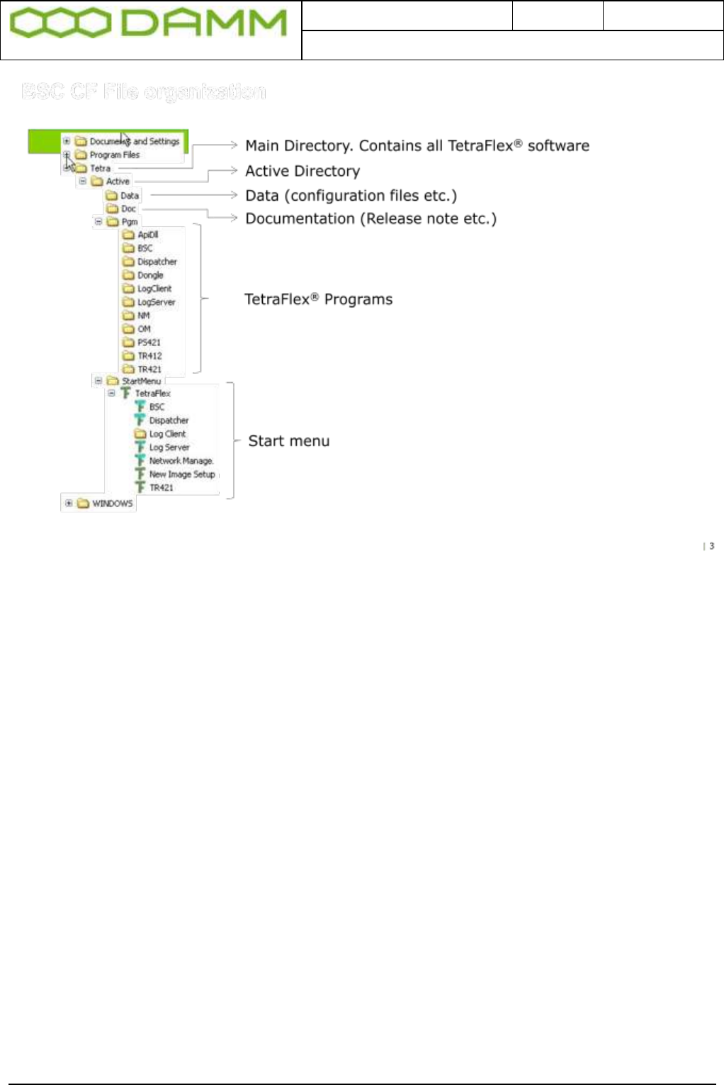
Doc. No.
Rev.
Date
DRAFT
1.01
2012-01-27
Damm Cellular Systems A/S, Denmark
TetraFlex® 7.5 Manual - Software installation
TetraFlex® 7.5
Manual
2-47
2.4.2 Windows License
The TetraFlex® has previously been delivered with the Windows XPe embedded OS
Due to outdate of XP from Microsoft, future systems will be delivered with Windows
Embedded Standard 2009 (WES2009)
The license label on the BSC will state which version is initially delivered.
Be aware that it is a violation of license to upgrade an XPe OS with WES2009 unless a new
license is purchased from sales.
A WES2009 can legally be downgraded to XPe should this be decided.
2.4.3 TetraFlex® Installation/Upgrade
2.4.3.1 Preconditions
The software package can be installed on either the SB421, BSC412 or on an external PC.
The Dispatcher and ApiDll, applications are compatible with the following operating systems:
o XP
o Windows 7
The BSC, Log Client, Log Server, NM and OM are compatible with the following operating
system:
o XP embedded

Doc. No.
Rev.
Date
DRAFT
1.01
2012-01-27
Damm Cellular Systems A/S, Denmark
TetraFlex® 7.5 Manual - Software installation
TetraFlex® 7.5
Manual
2-48
o Windows Embedded Standard 2009 (WES2009)
o XP
o Windows 7
o Windows Server 2008 R2
Installing the new Release can be done in different ways:
o Installing whole image including XP - relevant when upgrading SB421 and BSC412
from releases older than 7.30 e.g. 7.21 or new installation
o Installing whole image including WES 2009 (if the SB421 or BSC412 has a license
for WES2009) - relevant when upgrading SB421 and BSC412 from releases older
than 7.30 e.g. 7.21 or new installation
o Installing the TetraFlex packet or individual parts of the packet
2.4.3.2 Log Server running on Service Box with 2 Gbyte CF Card
If the Service Box has to run the Log Server program, the CF card has to be exchanged to
the new 8GByte CF card with the full TetraFlex packet including a preinstalled Log Server.
The actual TetraFlex configuration should be copied from the old to the new CF card (the
configuration is stored in C:\Tetra\Active\data\.
The Service box with the Log Server needs also to have 1GB RAM to function properly.
2.4.3.3 Installing a new image on SB421 and BSC412
If this procedure is not followed, and the upgrade is done remotely, the remote
connection to the system might be lost and it is necessary to go on site for
configuration.
NOTE: Always use CF-card delivered from DAMM that are prepared to be bootable from
either BSC 412 or SB421. Having any configuration files on the cf-card they should be
backed up, otherwise they are lost. If you want to be able to use the old sw version again
Copy drive C: (CF-P1) to drive D: (CF-P2).
The new image can be downloaded from DAMM’s web site (see chapter “Partners access to
Software Releases”.
Before using the image – please unzip. Use a PC and place the unzipped files in a directory
e.g. \Image.
Always check the Application Date Limit on the Dongle before installing new software. If the
the Application Date Limit is older than the date of the software version you are installing, it
will not work.
o Move the flash disk to an external card reader and check if it is formatted (C: NTFS
format, label CF-P1) and copy the new image to the partition CF-P1)
o Place the CF Card in the BSC412 or SB421 and reboot. After a while
the“FBReseale” dialog appears, please be patient it takes a while.

Doc. No.
Rev.
Date
DRAFT
1.01
2012-01-27
Damm Cellular Systems A/S, Denmark
TetraFlex® 7.5 Manual - Software installation
TetraFlex® 7.5
Manual
2-49
o Go to …\Tetra\Active\Pgm\BSC directory and open the file ImageSetup.bat file for
editing
o Edit the file (delete REM notes) for the configuration needed (recommendation is all
except headlines)
o Insert the correct IP and data (PC Name) in the top “set” lines (do not edit the bottom
“set” lines)
o Save the file
o DO NOT RUN. The bat file will be executed and then deleted the first time the
BSC.exe is started
o To make the BSC service and application start, make a copy of bsc.exe to bsc_.exe
The system configuration is stored in the the files CnfgBsc.txt, CngfBss.txt, CnfgMain.txt,
CnfgFact.txt and CnfgBs.txt in the \\Tetra\Active\Data folder. When these files are missing
they are auto-generated when the BSC application is started (with default values).
These files can also be generated with the following OM commands:
F70/SAVE CnfgBsc.txt
S70/SAVE -> CnfgBss.txt
M70/SAVE ->CnfgMain.txt
M90/FACTORYUNLOCK
M90/SAVE -> CnfgFact.txt
M90-
H71/SAVE-> CnfgBs.txt (used by BSC412 only)
After the files have been generated they must be edited with the correct IP address and other
parameters. Please see the chapter “SB421 configuration” and “BS41x Configuration” for
more details.
If you want to use DHCP server (recommend for SB421) this must be started manually. Go to
\Program files\DHCPserver and start the program DHCPsrv.exe. Install as service.
o NOTE This does NOT include the configuration of the LAN and WAN network card
settings in Windows. This must be done manually.
2.4.4 Installing individual parts of the TetraFlex packet.
All applications are preinstalled from factory on the SB421 and the BSC412, but can be re-
installed or installed on different external PC’s. Be aware of having the approriate dongles
when running the applications on various machines. Also check the Application Date Limit
before installing new releases.
Note: See also relevant upgrade guidelines and release notes when installing new
software.
2.4.4.1 BSC
1. If the system is already installed with TetraFlex® release 7.5 you only have to install the
new BSC software:

Doc. No.
Rev.
Date
DRAFT
1.01
2012-01-27
Damm Cellular Systems A/S, Denmark
TetraFlex® 7.5 Manual - Software installation
TetraFlex® 7.5
Manual
2-50
o Copy “…\Pgm\BSC\BSC.exe” into the active folder in the BSC “C:\Tetra\Active\”.
o Restart the BSC.
o Repeat the above two points for all BSC’s in the system.
2. If the system is installed with older TetraFlex releases please follow the Update guideline
for ver.7.4 to 7.5
3. If the installation is done on a new XP/ Windows installation, the following files should be
executed (If not already there the files could temporary be placed in the following path
“C:\Tetra\Active\pgm\BSC”):
o XpQosSetup.reg
o WinPcap_4_0_1.exe
o Restart the BSC via start menu “BSC Restart” or execute BSC.vbs and select
RESTART
4. If the installation is done on a PC with Windows 7, the following files should be executed
(If not already there the files could temporary be placed in the following path
“C:\Tetra\Active\pgm\BSC”):
o vbs-runas.reg (to allow BSC and BSC-GUI to run as administrator)
o XpQosSetup.reg
o WinPcap_4_0_1.exe
o Restart the BSC via start menu “BSC Restart” or excecute BSC.vbs and select
RESTART
In the “C:\Tetra\Active\” you will find a number of directories beside the pgm directory -
mentioned above-, these directories contain: system configuration files, the subscriber
database, and sound files to be used as part of the Tetra core features.
If a specific audio file doesn’t exist it is copied to the disk, when the service starts. User
generated sound files (in the C:\Tetra\Active\Audio folder) with different names as the
standards are kept.
Authentication keys need to be re-imported from the security key file from where they
originally were imported (and a renew of all keys must be performed).
2.4.4.2 Start Menu
The various TetraFlex parts can be started from the Windows start menu if the
C:\Tetra\Active\StartMenu\TetraFlex folder with all its content is copied to C:\Documents and
Settings\All Users\Start Menu.
2.4.4.3 OM
Stop the OM program - when running - before proceeding.
1. If the system is installed with TetraFlex release 7.5:
o Copy all files from “…\Pgm\OM\” into the active folder: “C:\Tetra\Active\PGM\OM”.
o Repeat this for all nodes in the system.
Doc. No.
Rev.
Date
DRAFT
1.01
2012-01-27
Damm Cellular Systems A/S, Denmark
TetraFlex® 7.5 Manual - Software installation
TetraFlex® 7.5
Manual
2-51
2. If the system is installed with older TetraFlex releases please follow the Update guideline
for ver.7.4x to 7.5
Having an OM shortcut on the desktop, change it to point at
“C:\Tetra\Active\pgm\OM\OM.vbs”.
2.4.4.4 NM
Stop the NM program - when running.
1. If the system is installed with TetraFlex release 7.5:
o Copy all files from “…\Pgm\NM\” into the active folder: “C:\Tetra\Active\PGM\NM”.
o Repeat this for all nodes in the system.
2. If the system is installed with older TetraFlex releases please follow the Update guideline
for ver.7.4x to 7.5
If there is a NM shortcut on the desktop, change it to point at
“C:\Tetra\Active\pgm\NM\NM.vbs”.
2.4.4.5 Dispatcher
The dispatcher application can only run on an external PC (not SB421 or BSC412) and the
PC must be provided with the appropriate dongle for starting the dispatcher.
The installation programs for the Dispatcher are default placed at the SB421 and BSC412
and can be installed on a external PC(s) from there.
Dispatcher installation programs:
When (re)starting the BSC, a Dispatcher distribution point is created via the TetraFlex share
under the folder structure: C:\Tetra\Share\Dispatcher\. Install the dispatcher on an external
PC by executing the Setup.exe file from this folder (to find the share use the File Explorer on
the PC where you want to install the Dispatcher).
For updating the dispatcher installation program on the the SB421 or BSC412, place the
dispatcher files in c:\tetra\share\dispatcher and c:\tetra\active\pgm\dispatcher.
Having any unwanted files in any of the above mentioned folders (e.g. from older
installations) please delete them before copying the new Dispatcher installation files.

Doc. No.
Rev.
Date
DRAFT
1.01
2012-01-27
Damm Cellular Systems A/S, Denmark
TetraFlex® 7.5 Manual - Software installation
TetraFlex® 7.5
Manual
2-52
If you are allowed to restart the BSC you may place the Dispatcher files in
c:\tetra\update\pgm\dispatcher\ They will then be copied to the right directory when activating
“BSC BackupUpdateRestart”
Having any unwanted files in any of the above mentioned folders (e.g. from older
installations) please delete them before copying the new Dispatcher installation files.
2.4.4.6 Log Server
The Log Server is available either as an external Log Server or installed on the 8GByte
Compact Flash card. The Log Server requires at least 1GB RAM to operate properly. The
log server is as default stopped and need to be restarted when needed.
To upgrade an existing Log Server to release 7.5 the Log Server must be stopped, all files
and folders from C: \Tetra\Active\Pgm\LogServer\ and C: \Tetra\Active\Pgm\LogClient\ must
be copied to the unit where the Log Server is installed. The Log Server can then be restarted
using the start menu TetraFlex → LogServer Restart. The Log Server is now running and the
Log Client installation files are ready for distribution via the "TetraFlex" share
C:\Tetra\Share\LogClient\
Note: The database for ver. 7.5 is not compatible with earlier versions. When restarting - the
new log server is making a copy of the old database - and it is starting with a new empty
database. The old database is stored in a folder with ver. no and date like:
\TetraFlexLogDB_4_0_20110912_103145
If you want to use the subscriber information in the Logserver from you ver. 7.4 database it
can be copied from the ver. 7.4 to ver 7.5 database following this procedure:
a. Stop the Log Server and MySql server service
b. Copy the following files from the old database to the new:
i. MsLogConfig.myd
ii. MsLogConfig.myi
iii. MsLogConfig.frm
c. Start the MySql server service and the Log Server again.
If using a database older than ver. 7.4 you have to contact DAMM for converting the
subscriber data.
2.4.4.7 Log Client
The Log Client applications may be installed on an external PC work station with the
appropriate dongle.
Install the Log Client by connecting to the Log Server (on SB421, BSC412 or external
logserver) with the file explorer. Find the folder Log Client using the TetraFlex share
(C:\Tetra\share\LogClient) and execute the LogClientInstall.vbs. When the Log Client shortcut
is executed, the new and the old LogClient.exe are compared. If they differ a backup of the
old Log Client files will be made and all the Log Client files are copied from the Log Server to
the local machine, except for the LogClient.ini file. If they are equal the local Log Client files
will be executed without copying.

Doc. No.
Rev.
Date
DRAFT
1.01
2012-01-27
Damm Cellular Systems A/S, Denmark
TetraFlex® 7.5 Manual - SB421 Configuration
TetraFlex® 7.5
Manual
2-53
2.4.4.8 PS421
The power supply software (PS421.hex) is placed in c:\tetra\active\pgm\PS421 directory.
The PS421 can be upgraded by using the OM command
M68/PS421/+
2.4.4.9 TR412
When unpacking the software package the TR412.bin file will be placed in
\Tetra\Active\Pgm\TR412.
Download this file to all TR412 by using the TetraOM command:
H68/TR412/A
2.4.4.10 BS421
Overwrite the existing TR421.dll file at C:\Tetra\Active\Pgm\TR421 with the new TR421.dll
On the local BSC execute the BS421Download.bat file (Path: C:\Tetra\Active\Pgm\TR421).
Restart all the TR’s by help of TetraOM commands:
99/RESTART
2.4.4.11 Installing TEA2 encryption
Files for TEA2 encryption are not part of the software package, but have to be ordered
separately. The TEA2 version of TR421.dll and TR412.bin are installed in the same way as
described above for BS421 and TR412.

Doc. No.
Rev.
Date
DRAFT
1.01
2012-01-27
Damm Cellular Systems A/S, Denmark
TetraFlex® 7.5 Manual - SB421 Configuration
TetraFlex® 7.5
Manual
2-54
2.5 SB421 CONFIGURATION
The SB421 enables you to connect a VGA monitor and a USB keyboard directly to the
SB421 without having an external PC.
In case no graphics is shown, press <Ctrl> + <Alt> + <F1> to reset the connection.
2.5.1 Initial setup
2.5.1.1 Ethernet Connection
The SB421 supports the following Ethernet connections, all auto negotiating
o 2 x 10/100 Mb/s Ethernet LAN connection for the Base Stations
o 1 x 10/100 Mb/s Ethernet WAN/LAN connection for remote operation and multi-node
backbone connection
o 2 x Ethernet type DC 1 second pulse connection for BS421 timing.
The Ethernet connections are LSA-type connections accepting only solid wires with the
dimension 0.4mm2 to 0.6mm2.
The Ethernet connections are protected by arresting devices.
The Ethernet connections are limited to SELV
The Ethernet WAN connection is connected to an Ethernet switch or directly to the PC /
Network by means of a straight or crossed Ethernet cable.
The Ethernet LAN connection shall solely be connected to the BS421(s) and optionally to a
redundant SB421 and/or IP backbone for multimode operation.
For redundant BSC operation, please see the chapter describing setup and requirements.
2.5.1.2 Turn on the SB421
Turn on the power to the BSC using SW101 on the Interconnection Board
Turn on the power to the BS421(s) using SW111 (TR1) and SW133 (TR2)
If changes in the BIOS are required, press F2 key shortly after applying power (while screen
is still blank)
Power up will take 2-3 minutes, mainly dependent on the startup time of operating system on
the SB421.
After successful power up, check the BSC LED’s for proper function as described in section
1.1.4.4.4
2.5.1.3 System BIOS configuration
To enter the BIOS setup application, press F2 during initial boot of the SB421
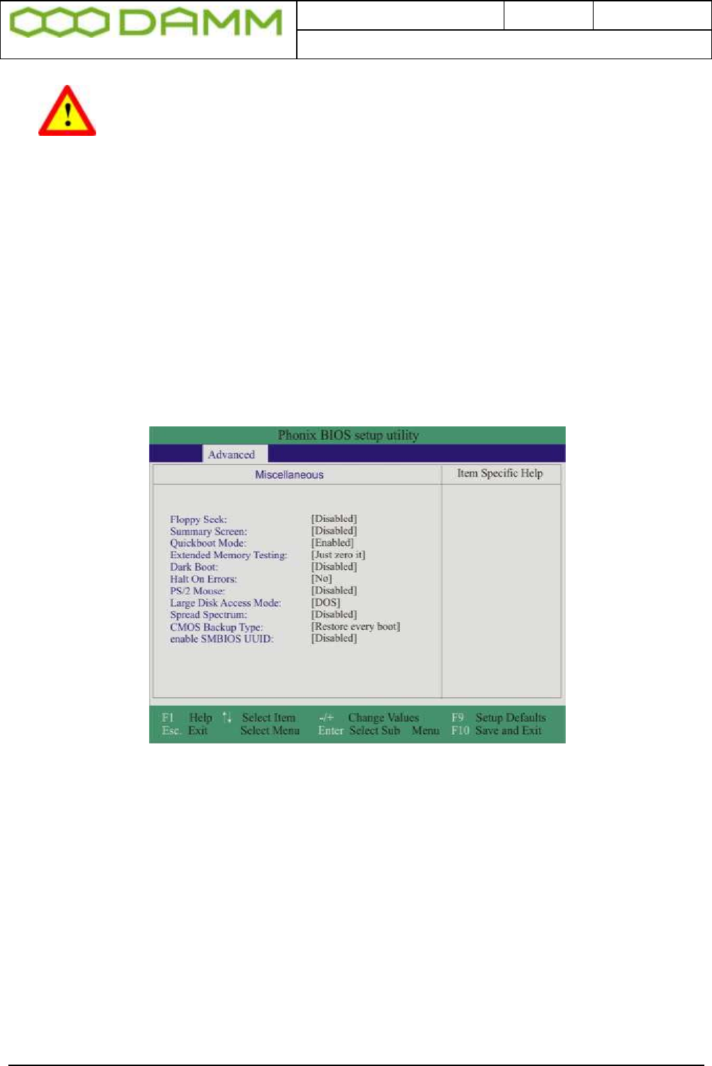
Doc. No.
Rev.
Date
DRAFT
1.01
2012-01-27
Damm Cellular Systems A/S, Denmark
TetraFlex® 7.5 Manual - SB421 Configuration
TetraFlex® 7.5
Manual
2-55
WARNING: Be careful not to disable the USB ports in the BIOS. When USB
ports are disabled, the dongle cannot be read and there is no way of getting
direct access to the SB421 PC by means of a monitor and keyboard / mouse.
2.5.1.3.1 Hard disk disable
NOTE: In case of an internal hard disk is present, disable this totally before booting from the
CF card. After initial boot the HD may be enabled again and should appear as D:\ drive with a
2GB CF card installed and F:\ with an 8GB CF card installed.
DO NOT try to reconfigure drive letters with the build-in drive manager in the OS
2.5.1.3.2 BIOS setup for the TetraFlex® V7.30 and newer (CF Boot)
Please configure the BIOS according to the following screenshots
Figure 2-3: Miscellaneous
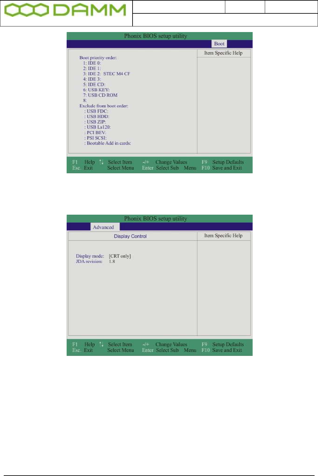
Doc. No.
Rev.
Date
DRAFT
1.01
2012-01-27
Damm Cellular Systems A/S, Denmark
TetraFlex® 7.5 Manual - SB421 Configuration
TetraFlex® 7.5
Manual
2-56
Figure 2-4: Boot configuration
Figure 2-5: Display configuration
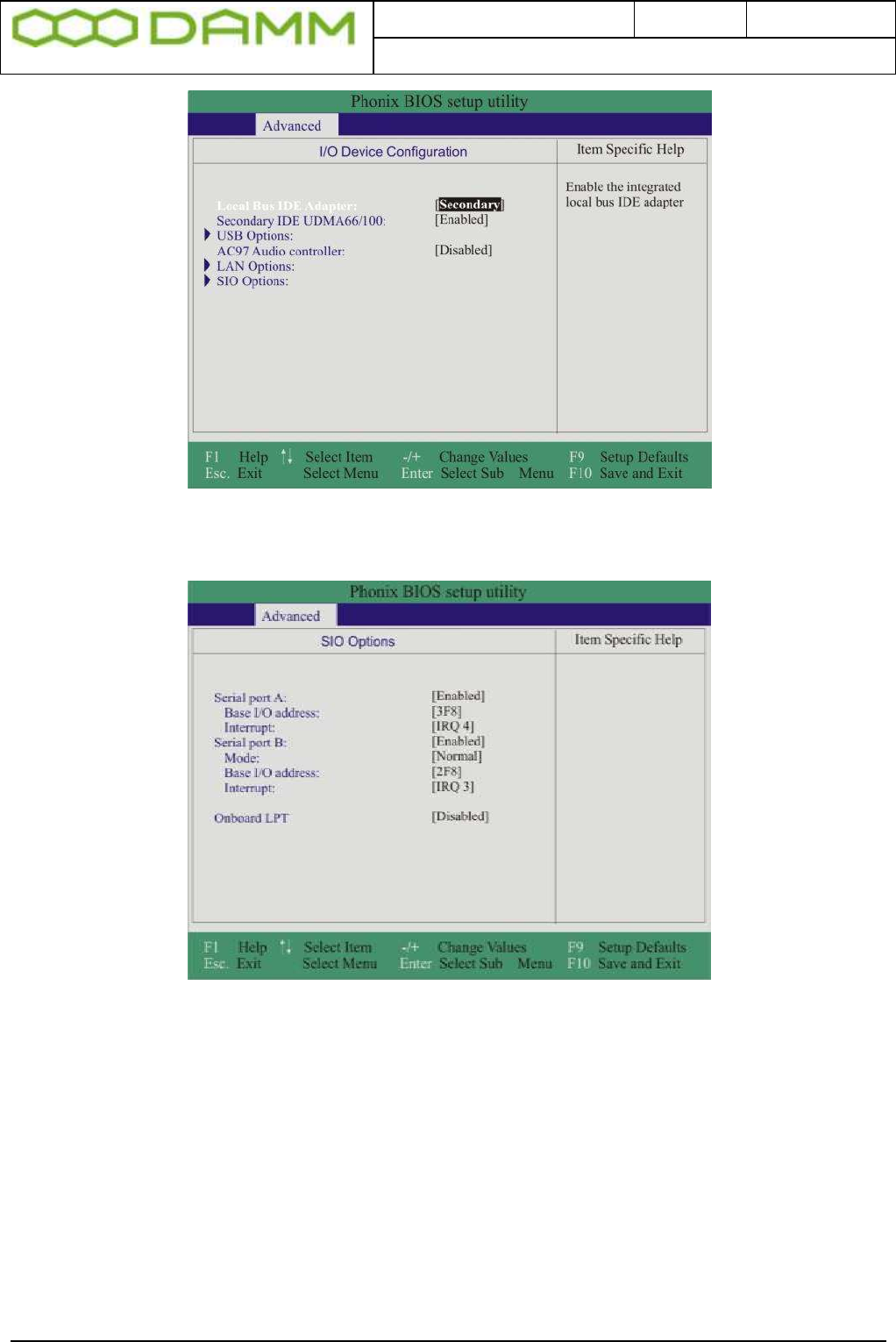
Doc. No.
Rev.
Date
DRAFT
1.01
2012-01-27
Damm Cellular Systems A/S, Denmark
TetraFlex® 7.5 Manual - SB421 Configuration
TetraFlex® 7.5
Manual
2-57
Figure 2-6: I/O selection
Figure 2-7: Port configuration
2.5.1.3.3 BIOS setup for new fast Compact Flash (CF) Cards
Due to a BIOS incompatibility, the use of new CF cards requires a change in the BIOS set up:
o Enter the BIOS setup by pressing F2 key under boot
o Select the MAIN area
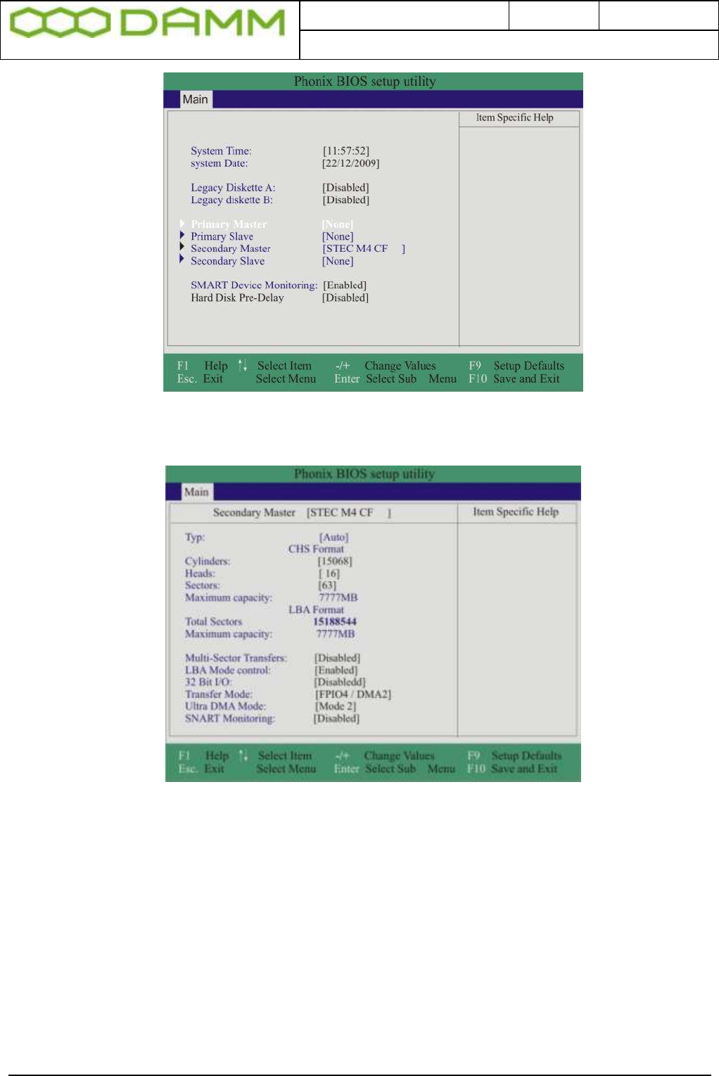
Doc. No.
Rev.
Date
DRAFT
1.01
2012-01-27
Damm Cellular Systems A/S, Denmark
TetraFlex® 7.5 Manual - SB421 Configuration
TetraFlex® 7.5
Manual
2-58
Figure 2-8: BIOS main selection
o Select Secondary Master
Figure 2-9: USER type change
o Select “TYPE” and change type to “Auto” by tapping the <Space> key
o Press <F10> to save the setting and exit the BIOS setup
2.5.1.4 IP address set-up
For the TetraFlex® system all IP addresses except for multi node networking is preset upon
delivery. The only setup necessary is the IP addresses for the WAN used for application GW,
network management, remote desktop connection, log server client, and dispatcher client.
These IP addresses are entirely user dependent and they are setup using the WAN Ethernet
board configuration in Windows operation system.

Doc. No.
Rev.
Date
DRAFT
1.01
2012-01-27
Damm Cellular Systems A/S, Denmark
TetraFlex® 7.5 Manual - SB421 Configuration
TetraFlex® 7.5
Manual
2-59
2.5.1.4.1 Default network card IP address setup
As default the IP addresses are defined as
o LAN Network Card: 172.16.1.10
This IP address must be equal to the IP address defined for the BSC
If these IP’s addresses are miss-configured, in addition to a non working system,
also a PS alarm may show on the BSC LED’s
o WAN Network Card: DHCP
2.5.1.5 MAC address Set-up
On delivery from DAMM, the MAC is set to the correct value
BSC´s delivered from 01.01.2008 has the MAC address stored in a flash device. No action
needed.
BSC´s delivered before 01.01.2008 (MAC address label may be present on the BSC unit)
may have the MAC redefined.
The MAC is stored on the storage device (HD or CF). This means that if the system is cloned
from another SB421 or reinstalled with the image file available at the http://www.damm.dk,
the MAC address MUST be changed from the MAC specified in the source file to the actual
value valid for the specific SB421 serial number.
If MAC cannot be determined, contact support@damm.dk with the serial number in question
To enter / change the MAC, follow the procedure as stated.
o Look up and write down the MAC address noted on the label placed in the upper
right corner of the CPU (BSC) unit in the SB421. See
o Figure 1-2: BSC421
o Use the file explorer and go to C:\Programs\MacMakeUp\MacMakeup.exe
Figure 2-10: Start MacMakeUp Application
o In the MacMakeUp application select the 8255xER PCI Adapter
o Enter the MAC address (Enter value like 000FE3000431)
o Press “Change”
o Close the application
o Re-open MacMakeUp and check that the MAC is actually changed / saved
o Disable and then enable the WAN net card to make MAC change valid.

Doc. No.
Rev.
Date
DRAFT
1.01
2012-01-27
Damm Cellular Systems A/S, Denmark
TetraFlex® 7.5 Manual - BS421 Configuration
TetraFlex® 7.5
Manual
2-60
Figure 2-11: Change MAC
2.6 BS421 CONFIGURATION
2.6.1 Ethernet Connection
The BS421 supports 1 x 10/100 Mb/s. Ethernet connection and 1 x Ethernet type DC
connection for timing.
The purpose of the connections is
o To establish SB421 connection for control of the base station
o To establish connection to another BS421 for timing and synchronization. (1 sec
Pulse).
The Ethernet connections are limited to SELV (Safety Extra Low Voltage) connections.
The Ethernet connection shall be connected directly to the SB421 TR connection board.
The DC timing connection is connected through the SB421 LAN cable. Arresting units are an
integrated part of the SB421.
.
2.6.1.1 Set-up of IP address
2.6.1.1.1 DHCP (Typical TetraFlex® single node)
The IP address and the net mask is setup by means of DHCP.
When the system is delivered from DAMM, the BSC and the BS421 are paired and should
start-up without any need of configuration change.
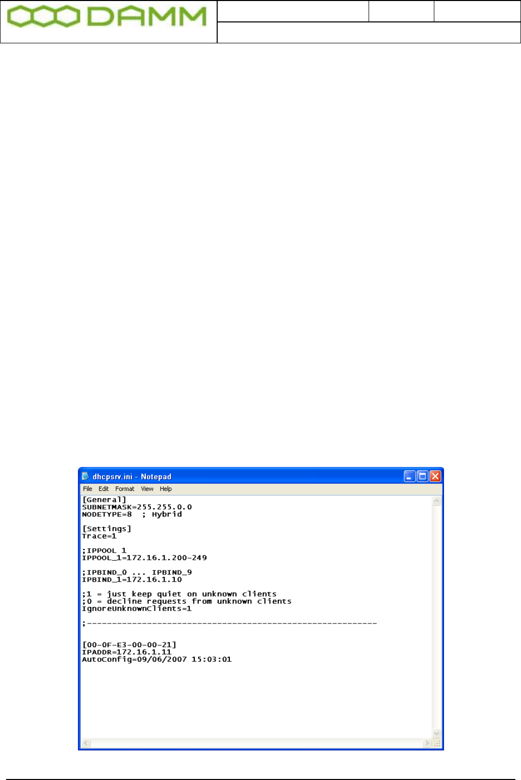
Doc. No.
Rev.
Date
DRAFT
1.01
2012-01-27
Damm Cellular Systems A/S, Denmark
TetraFlex® 7.5 Manual - BS421 Configuration
TetraFlex® 7.5
Manual
2-61
However, if the BS421 is connected to another BSC, the IP address configuration must be
reset.
2.6.1.1.2 How does DHCP work with the SB421 (BSC)?
The IP address may be assigned by means of DHCP.
This means that the SB421 must first be started. When the SB421 is started her after the
BS421/1 must be started and then in a dual carrier system the BS421/2.
The BS421 gets an IP address from the PC’s DHCP server. This IP address is tied to the
BS421 MAC address.
If the MAC address is unknown to the PC, the BS421 will be assigned an IP in the range
172.16.1.200 - 249.
In this case the BS421 IP address must be changed.
2.6.1.1.3 Changing the BS421 IP
o Open C:\Program Files\DHCPServer\dhcpsrv.ini with notepad or another text editor.
o (Hint: save a backup of the original file before editing)
NOTE: All entries above the dotted line are factory presets and must only be changed for
redundant SB421 (change IP Bind to 172.16.1.19) or when IP address segments must be
changed.
Figure 2-12: DHCP Setup
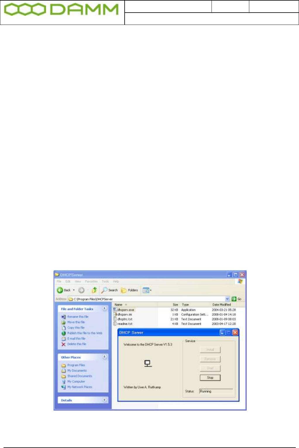
Doc. No.
Rev.
Date
DRAFT
1.01
2012-01-27
Damm Cellular Systems A/S, Denmark
TetraFlex® 7.5 Manual - BS421 Configuration
TetraFlex® 7.5
Manual
2-62
o Below the dotted line one or more MAC [In Brackets] / IP addresses are shown.
o If only one MAC / IP is shown, change the IP address to 172.16.1.11
o If more IP’s are shown and only one BS421 is connected, determine which IP
address is valid by use of a ping command to the IP’s. Delete the wrong IP / MAC
entries and change the remaining IP to 172.16.1.11
o If more IP’s are shown and two BS421 is connected, determine which IP’s are valid
by use of a ping command to the IP’s. Delete the wrong IP/MAC entries and change
the remaining IP’s to 172.16.1.11 for the first BS421 and 172.16.1.12 for the second
BS421 and so on. Observe the correct MAC / IP combination.
o NOTE: It is highly recommended to assign IP’s to one BS at a time by shutting of the
power to the other.
o Save the dhcpsrv.ini file
o Restart BS421 by means of the appropriate switch (SW111 and SW133 ) inside the
SB421 or use TetraOM PS command 11- / 11+ and 12- /12+
o Ping the 172.16.1.11(TR1) and 12 (TR2) to check if the addresses are correct
2.6.1.1.3.1 DHCP with redundant SB421
With redundant SB421 the procedure for DHCP also applies, but the redundant SB421
communication with the BS421(s) is (are) initially off line (DHCP server stopped).
To stop the DHCP server, log in to C:\ProgramFiles\DHCPserver and double click on the
dhcpsrv.exe file
Figure 2-13: DHCP Redundant Setup

Doc. No.
Rev.
Date
DRAFT
1.01
2012-01-27
Damm Cellular Systems A/S, Denmark
TetraFlex® 7.5 Manual - BS421 Configuration
TetraFlex® 7.5
Manual
2-63
Then select “STOP” to temporarily stop the DHCP server.
When the IP setup of the main SB421 is finished,
o The dhcpsrv.ini file must be copied to the C:\ProgramFiles\DHCPserver of the
redundant SB421
o The IPBIND setting must be changed from IPBIND_1=172.16.1.10 to
IPBIND_1=172.16.1.19
o The DHCP server must be started up again
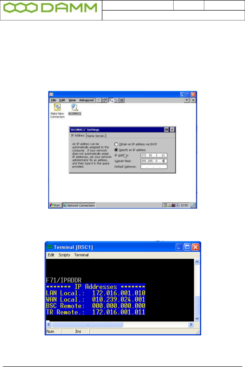
Doc. No.
Rev.
Date
DRAFT
1.01
2012-01-27
Damm Cellular Systems A/S, Denmark
TetraFlex® 7.5 Manual - BS421 Configuration
TetraFlex® 7.5
Manual
2-64
2.6.1.1.4 Static IP
Setting the TR with Static IP address (Default is dynamic ):
o Open the VNC for the selected BS421
o Select START -> Settings -> Network and dial up connections
o Open the AU1MAC1
o Select Specify an IP address and enter the relevant data into the fields
o Select OK and exit the program
Figure 2-14: Static IP setup
o Using TetraOM command F71/…, check or change the IP for BS1 (TR remote)
Figure 2-15: TetraOM IP definition

Doc. No.
Rev.
Date
DRAFT
1.01
2012-01-27
Damm Cellular Systems A/S, Denmark
TetraFlex® 7.5 Manual - BS421 Configuration
TetraFlex® 7.5
Manual
2-65
2.6.1.1.5 TR421 Update / Install
For updating the transceiver program; TR421.dll on the BS421, use this procedure:
o Change the IP addresses used in “TR421Download.bat” file (path
c:\tetra\active\pgm\TR421\) with the actual IP addresses to match the TR421's.
o The address of the first TR is default 172.16.x.11 where x is the node number (IP
must be written in the bat-files without the leading zeros).
o “Rem” out all unused TR421's
Default TR421Download.bat:
@echo *********************************************************
@echo ***** TR421 file download *****
@echo *********************************************************
@echo Copyright 1985-2009
@echo Damm Cellular Systems A/S, Denmark
@echo Ver. 7.40 2009-09-17
@echo Change all the IP Addresses below to match the BS421's
@echo rem out all unused BS421's
@echo ********** Copy files to TR421-1 *********
net use Z: \\172.16.1.11\CF-Card tetra /USER:tetra /PERSISTENT:NO
copy TR421.dll Z:\Tetra\Pgm\Tr\*.* /Y
copy TR421.bat Z:\Tetra\Pgm\Tr\*.* /Y
net use Z: /DELETE
rem @echo ********** Copy files to TR421-2 *********
rem net use Z: \\172.16.1.12\CF-Card tetra /USER:tetra /PERSISTENT:NO
rem copy TR421.dll Z:\Tetra\Pgm\Tr\*.* /Y
rem copy TR421.bat Z:\Tetra\Pgm\Tr\*.* /Y
rem net use Z: /DELETE
rem @echo ********** Copy files to TR421-3 *********
rem net use Z: \\172.16.1.13\CF-Card tetra /USER:tetra /PERSISTENT:NO
rem copy TR421.dll Z:\Tetra\Pgm\Tr\*.* /Y
rem copy TR421.bat Z:\Tetra\Pgm\Tr\*.* /Y
rem net use Z: /DELETE
rem @echo ********** Copy files to TR421-4 *********
rem net use Z: \\172.16.1.14\CF-Card tetra /USER:tetra /PERSISTENT:NO
rem copy TR421.dll Z:\Tetra\Pgm\Tr\*.* /Y
rem copy TR421.bat Z:\Tetra\Pgm\Tr\*.* /Y
rem net use Z: /DELETE
@echo Please restart all TR421 services afterwards
@echo by executing B/99/RESTART from BSC
pause
On the local BSC execute “BS421Download.bat” file (Path “C:\Tetra\Active\Pgm\TR421”):
Restart all TR’s by using the TetraOM commands:
99/RESTART

Doc. No.
Rev.
Date
DRAFT
1.01
2012-01-27
Damm Cellular Systems A/S, Denmark
TetraFlex® 7.5 Manual - BS421 Configuration
TetraFlex® 7.5
Manual
2-66
NB: Update only NK.BIN and Boot.ini if you are adviced to do so (in case they are damaged
or need to be updated).
Installation of NK.bin file (Windows CE): Refer to section 2.6.2.1
Installation of the Boot.bin file:
o Copy the Boot.bin file to the root of the TR421 CF-Card.
o Restart the TR421 with the command
99/RESTART
o Reboot the TR421 with command to the PS421, commands
AP (Address the Power supply)
11- (power off for TR1 and TR3
11+ (power on for TR1 and TR3)
12- (power off for TR2 and TR4)
12+ (power on for TR2 and TR4)
2.6.2 Installing Windows CE on BS421
The operating system on BS421 is Windows CE that is contained in one file - NK.bin this
chapter describes how to install it.
IMPORTANT:
Do not copy NK.bin (WinCE) to the BS421 unless instructed to do so, or forced to do
so due to breakdown.
2.6.2.1 Copy NK.bin (WinCE) to BS421
If the BS421 is connected with VNC, the BS application (TR421) MUST be stopped before
copying files. Enter 99/STOP <Enter> in the OM Command Interpreter and the application
stops and shows the normal WinCE desktop
WARNING: If the BS application is not stopped before copying, the connection to the
BS421 may be lost. In this case proceed as follows:
o Disassemble the BS421
o Take out the CF-Card
o Put the CF-card into an compatible card reader
o Manually copy the NK.bin file to the CF card
o Put the CF-card back in the BS421
o Reassemble the BS421 and proceed as described in section 2.6.2.2
If communication with BS421 is present, proceed as follows

Doc. No.
Rev.
Date
DRAFT
1.01
2012-01-27
Damm Cellular Systems A/S, Denmark
TetraFlex® 7.5 Manual - BS421 Configuration
TetraFlex® 7.5
Manual
2-67
o Search for BS421 using Start -> Search -> Files or Folders -> Computer
o Enter the IP address of the BS421 e.g. 172.16.1.11 or 172.16.1.12
o Select Search
o Select the search result
o Select CF-Card
o Create a new directory called CF-Card\TMP on the BS421
o Copy the file NK.bin from SB421 C:\tetra\PGM\TR to the CF-Card\TMP on BS421
o Open VNC for TR1 or TR2 from the desktop
o Open My Device
o Copy NK.bin from CF-Card\TEM to CF-Card
o Accept overwrite of old NK.bin file
The copy function takes app. 15 min.
Note: If for some reason the connection to the system is broken, the copying of the file will
continue locally. Just wait until the copying has finished (minimum 15-20 minutes) before
restart.
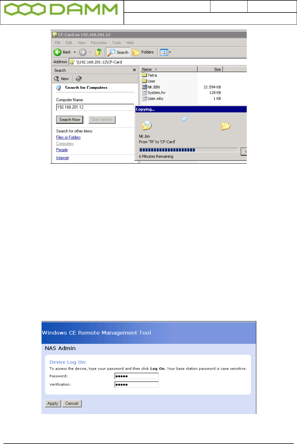
Doc. No.
Rev.
Date
DRAFT
1.01
2012-01-27
Damm Cellular Systems A/S, Denmark
TetraFlex® 7.5 Manual - BS421 Configuration
TetraFlex® 7.5
Manual
2-68
Figure 2-16: NK.BIN copy
o After successful copy, delete the CF-Card\TMP directory
o Restart BS421 using switch in SB421
2.6.2.2 Configure admin user
When a new NK.bin file has been copied to the BS421, the BS421 Admin and User settings
are lost. To reestablish, follow the procedure:
o Start the Internet Explorer from SB421 Start -> Programs -> Internet Explorer
o Connect to the file-server web client on BS421 using:
http://”TRx IP address”/remoteadmin
(“TRx IP address” = 172.16.1.11 for TR1 or 172.16.1.12 for TR2)
o Password = tetra
o Verification = tetra
o Select Apply
Figure 2-17: Configure Admin and User
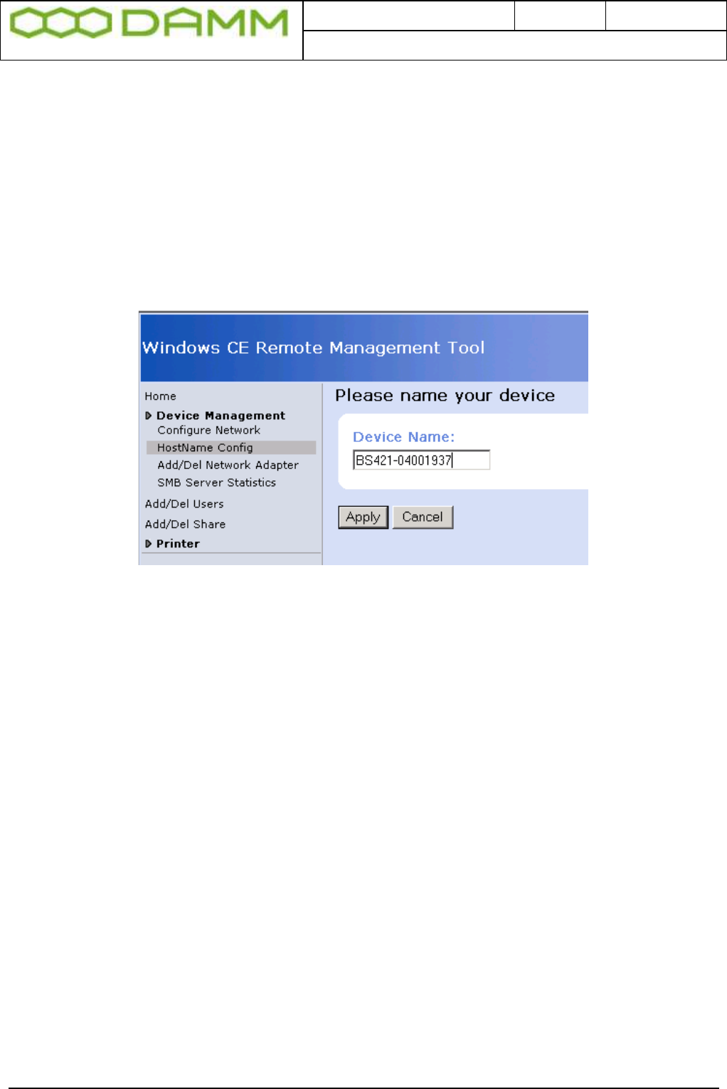
Doc. No.
Rev.
Date
DRAFT
1.01
2012-01-27
Damm Cellular Systems A/S, Denmark
TetraFlex® 7.5 Manual - BS421 Configuration
TetraFlex® 7.5
Manual
2-69
The gateway will restart and prompt for username and password
o Enter username = admin
o Enter password = tetra
2.6.2.3 Configure host name
o Insert BS421-“BS421 serial number”
o Press Apply. To move on, it might be necessary to temporarily make a change to
the Device Name and press <Apply>. Immediately change it back to the original
name and press <Apply>, then move to on to the next point
Figure 2-18: Configure Host Name
2.6.2.4 Configure file-server user
o Select add/del User
o Enter username = tetra
o Enter password = tetra
o Enter confirm = tetra
o Press Add New or <Enter>
o Check user tetra has been added and exit the browser

Doc. No.
Rev.
Date
DRAFT
1.01
2012-01-27
Damm Cellular Systems A/S, Denmark
TetraFlex® 7.5 Manual - BS421 Configuration
TetraFlex® 7.5
Manual
2-70
Figure 2-19: Configure user and password
2.6.3 Copy to and from Compact Flash Card (CF Card) on BS421
o Use Explorer to connect to BS421
o Start -> Search -> For files or folders -> Computers
o Enter TRx IP address 172.16. 1.11 for TR1, 172.16.1.12 for TR2 and so on
o Check that the S/N is correct
o When connected, update the CF card as required