Damm Cellular Systems A S 104012 410 MHZ TRANSCEIVER MODULE User Manual TetraFlex 7 5 Manual
Damm Cellular Systems A/S 410 MHZ TRANSCEIVER MODULE TetraFlex 7 5 Manual
Contents
- 1. User Manual - 1
- 2. User manual - 2
- 3. User Manual - 3
- 4. User Manual - 4
- 5. Warning statements for user's manual
- 6. Notes to installer for user manual
- 7. Revised pages 4 and 5 of the user's manual 11 01 2012
- 8. User addendum 4 carrier 11 01 12
- 9. User addendum 8 carrier 11 01 2012
- 10. Note to installers to be placed in user manual
User Manual - 1

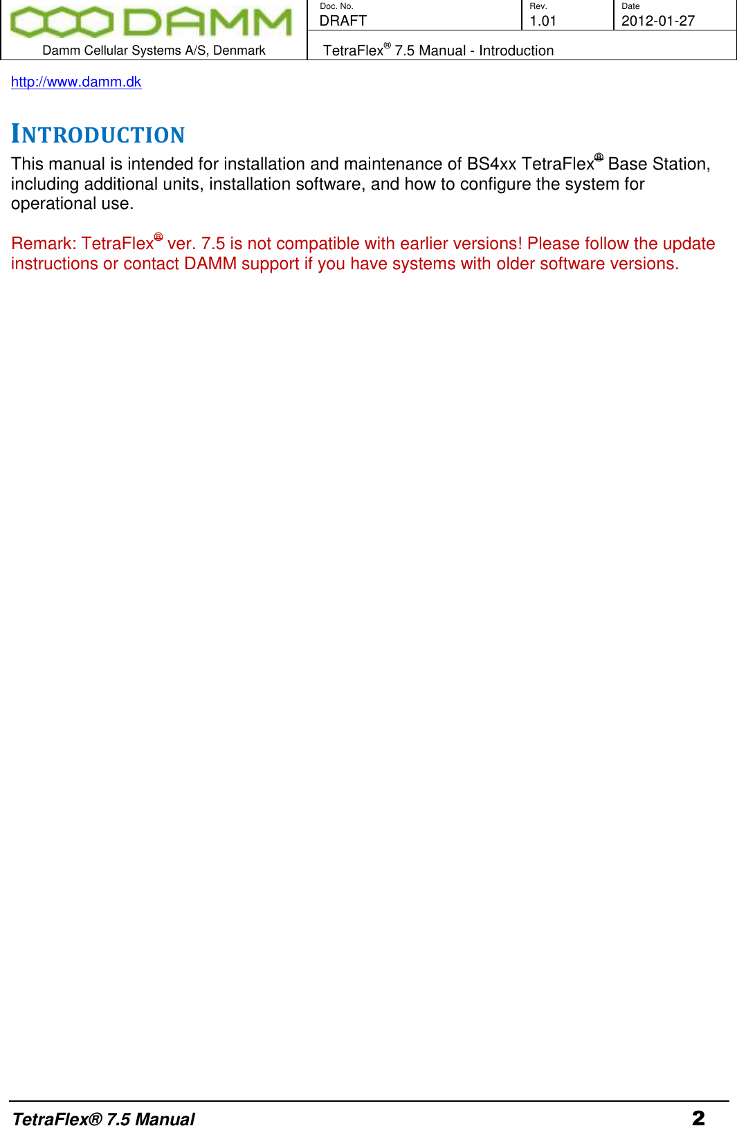
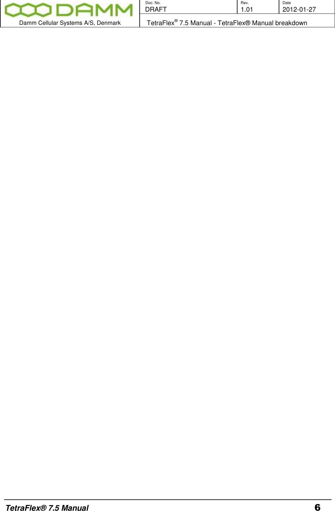
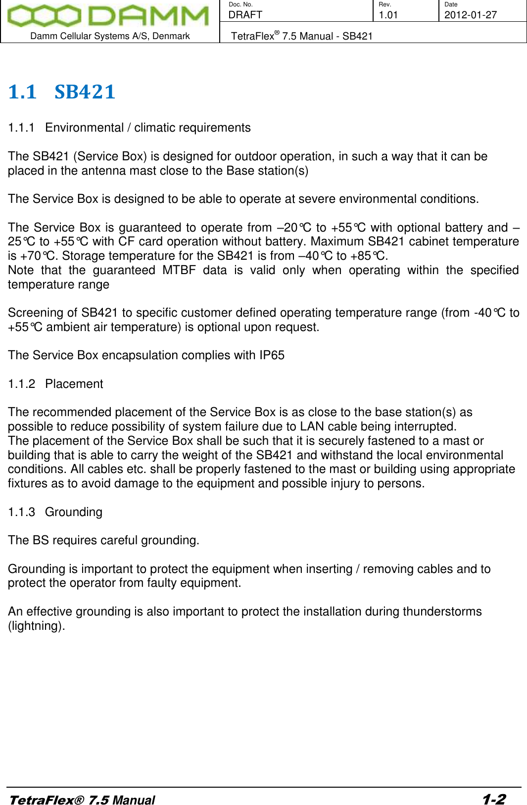

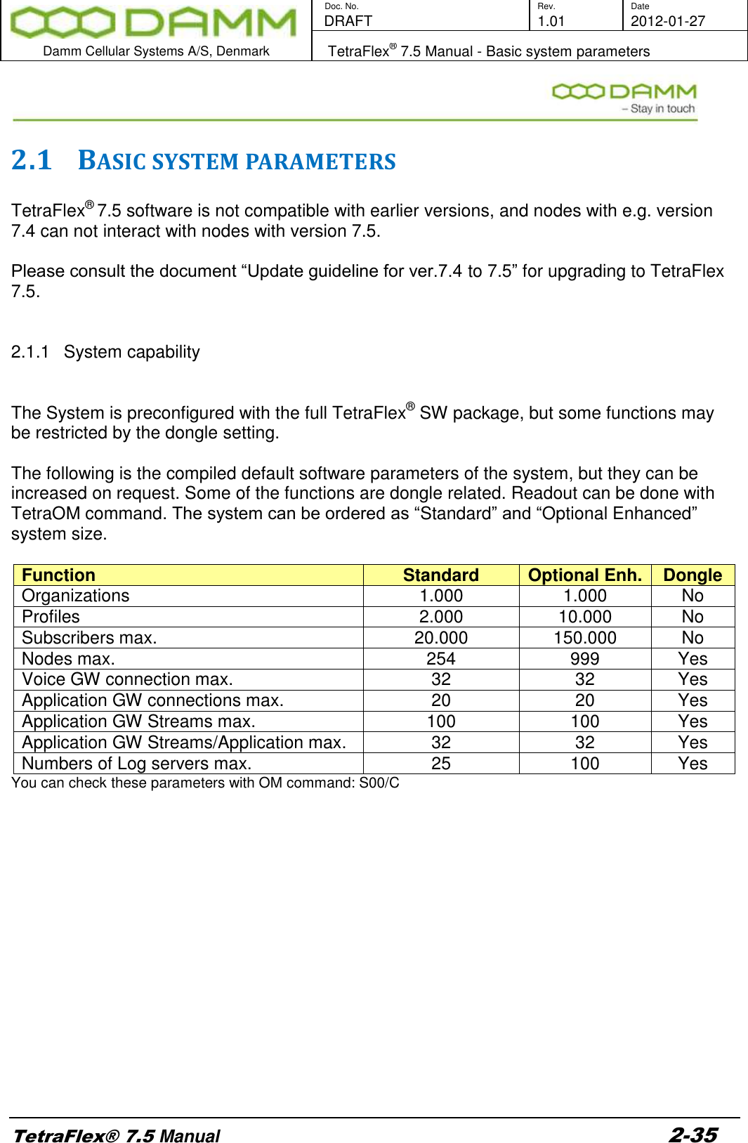
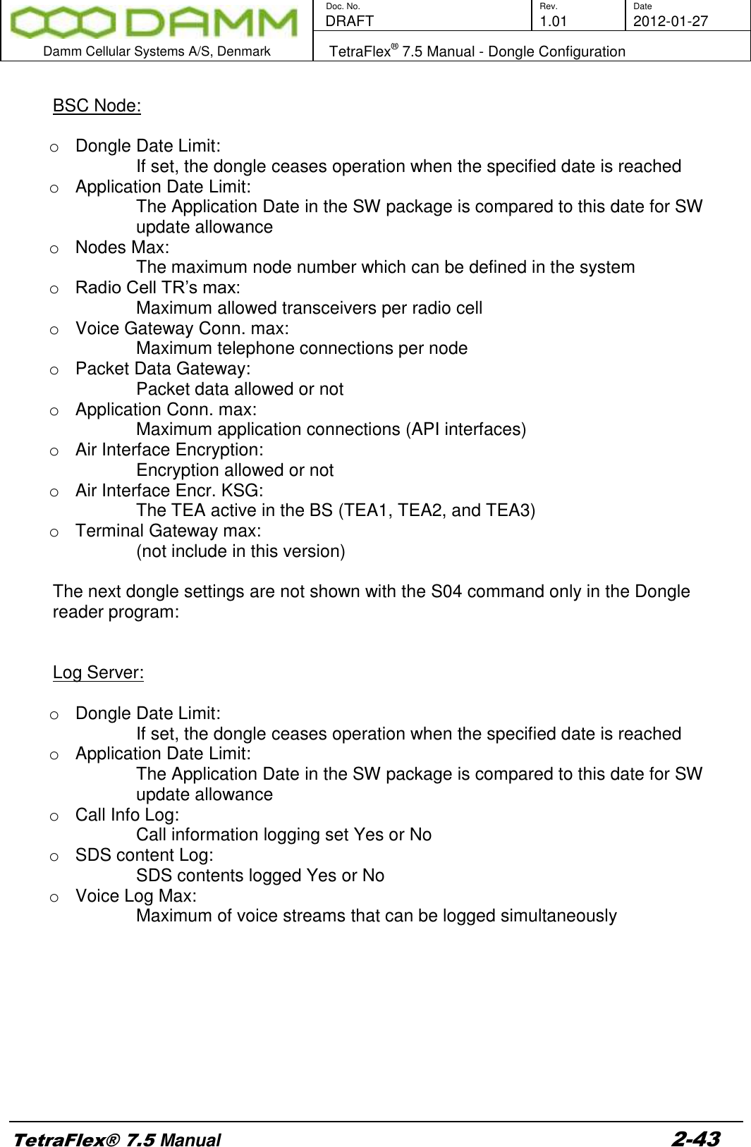
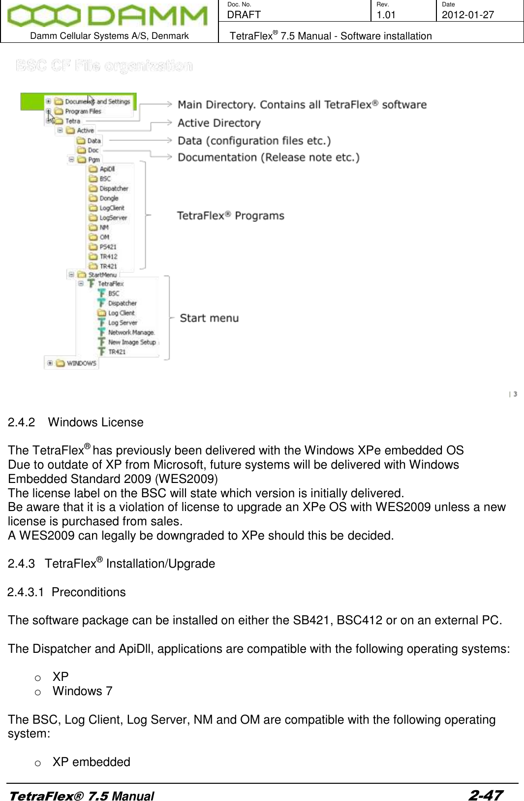
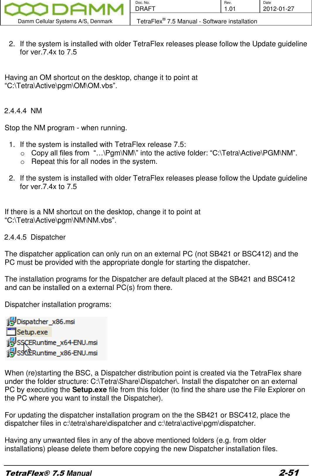
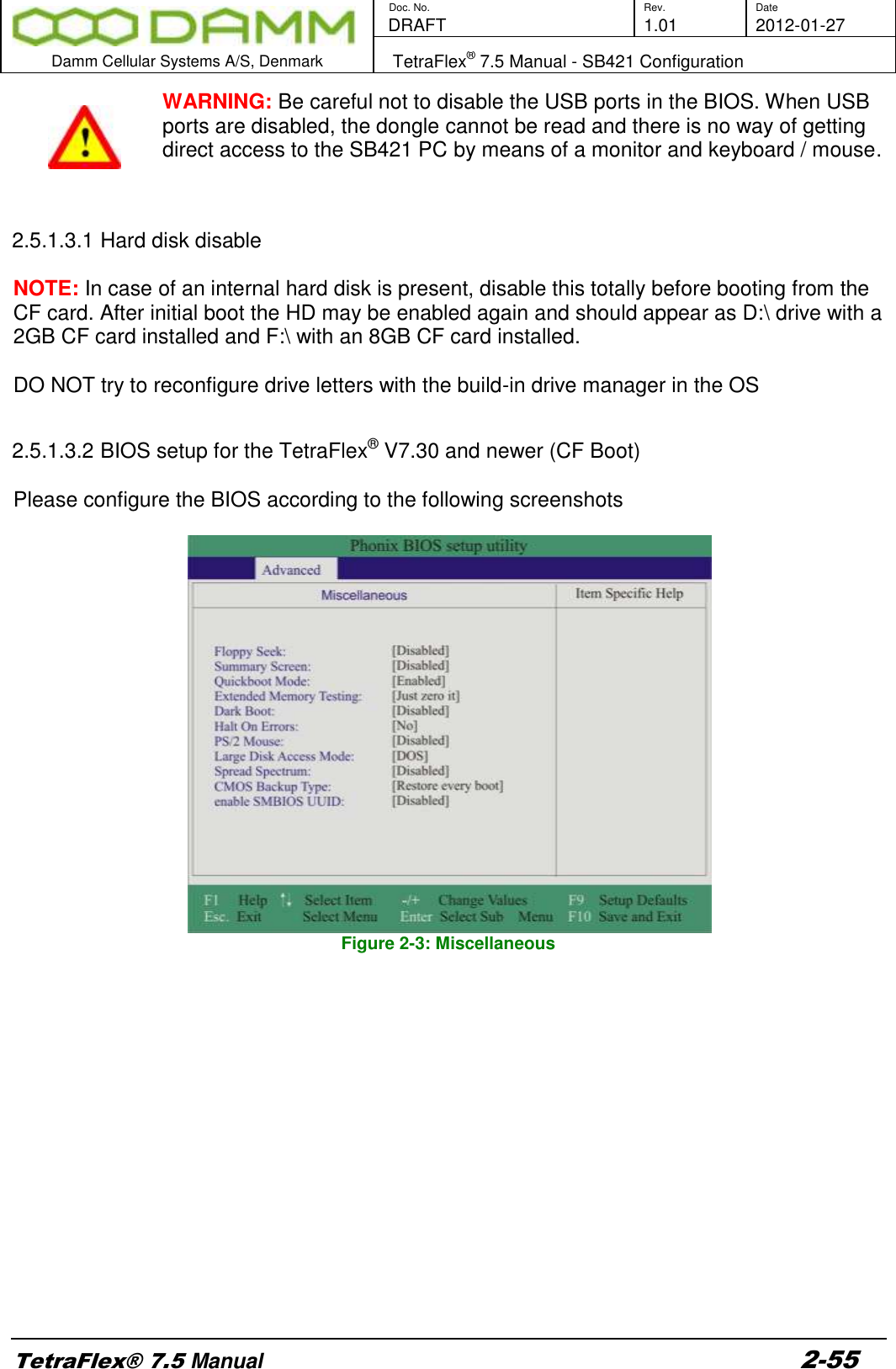
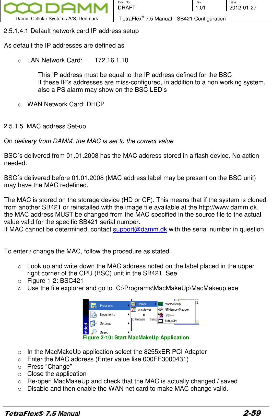
![Doc. No. Rev. Date DRAFT 1.01 2012-01-27 Damm Cellular Systems A/S, Denmark TetraFlex® 7.5 Manual - BS421 Configuration TetraFlex® 7.5 Manual 2-62 o Below the dotted line one or more MAC [In Brackets] / IP addresses are shown. o If only one MAC / IP is shown, change the IP address to 172.16.1.11 o If more IP’s are shown and only one BS421 is connected, determine which IP address is valid by use of a ping command to the IP’s. Delete the wrong IP / MAC entries and change the remaining IP to 172.16.1.11 o If more IP’s are shown and two BS421 is connected, determine which IP’s are valid by use of a ping command to the IP’s. Delete the wrong IP/MAC entries and change the remaining IP’s to 172.16.1.11 for the first BS421 and 172.16.1.12 for the second BS421 and so on. Observe the correct MAC / IP combination. o NOTE: It is highly recommended to assign IP’s to one BS at a time by shutting of the power to the other. o Save the dhcpsrv.ini file o Restart BS421 by means of the appropriate switch (SW111 and SW133 ) inside the SB421 or use TetraOM PS command 11- / 11+ and 12- /12+ o Ping the 172.16.1.11(TR1) and 12 (TR2) to check if the addresses are correct 2.6.1.1.3.1 DHCP with redundant SB421 With redundant SB421 the procedure for DHCP also applies, but the redundant SB421 communication with the BS421(s) is (are) initially off line (DHCP server stopped). To stop the DHCP server, log in to C:\ProgramFiles\DHCPserver and double click on the dhcpsrv.exe file Figure 2-13: DHCP Redundant Setup](https://usermanual.wiki/Damm-Cellular-Systems-A-S/104012.User-Manual-1/User-Guide-1739420-Page-82.png)