Damm Cellular Systems A S 104012 410 MHZ TRANSCEIVER MODULE User Manual TetraFlex 7 5 Manual
Damm Cellular Systems A/S 410 MHZ TRANSCEIVER MODULE TetraFlex 7 5 Manual
Contents
- 1. User Manual - 1
- 2. User manual - 2
- 3. User Manual - 3
- 4. User Manual - 4
- 5. Warning statements for user's manual
- 6. Notes to installer for user manual
- 7. Revised pages 4 and 5 of the user's manual 11 01 2012
- 8. User addendum 4 carrier 11 01 12
- 9. User addendum 8 carrier 11 01 2012
- 10. Note to installers to be placed in user manual
User manual - 2
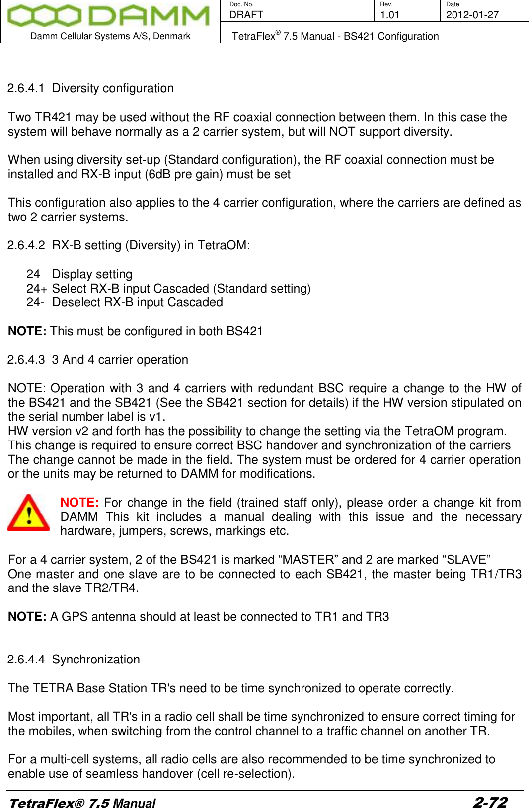
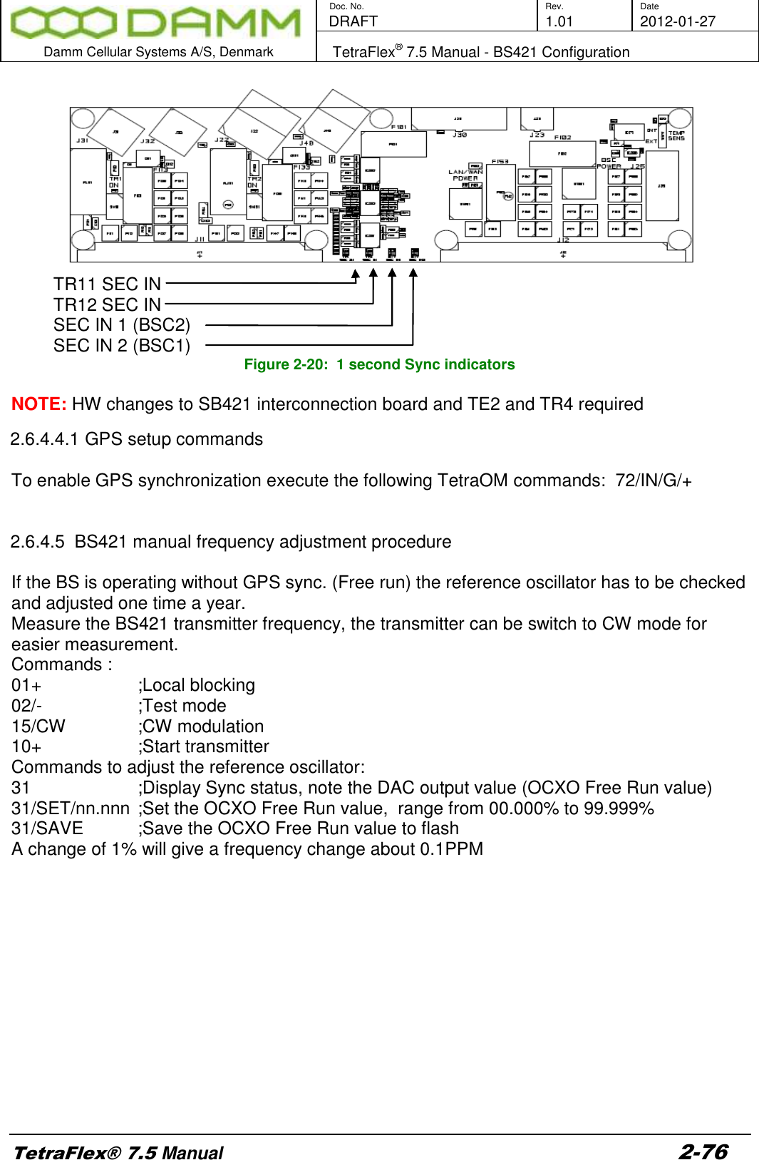
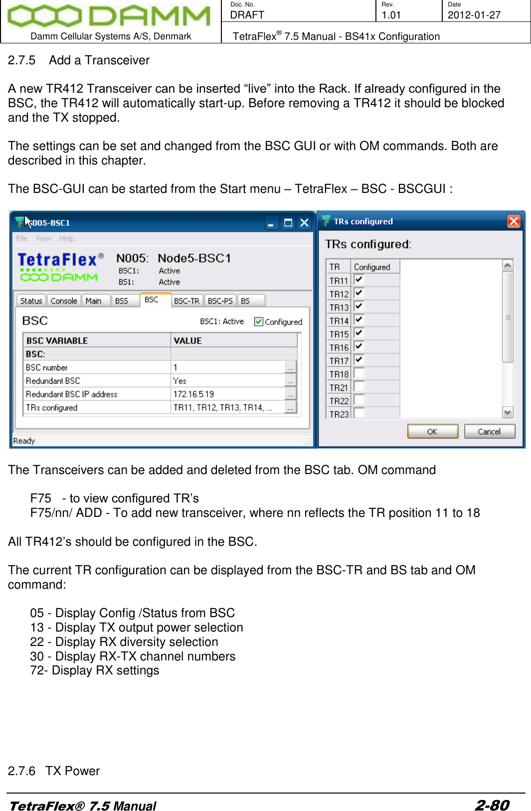
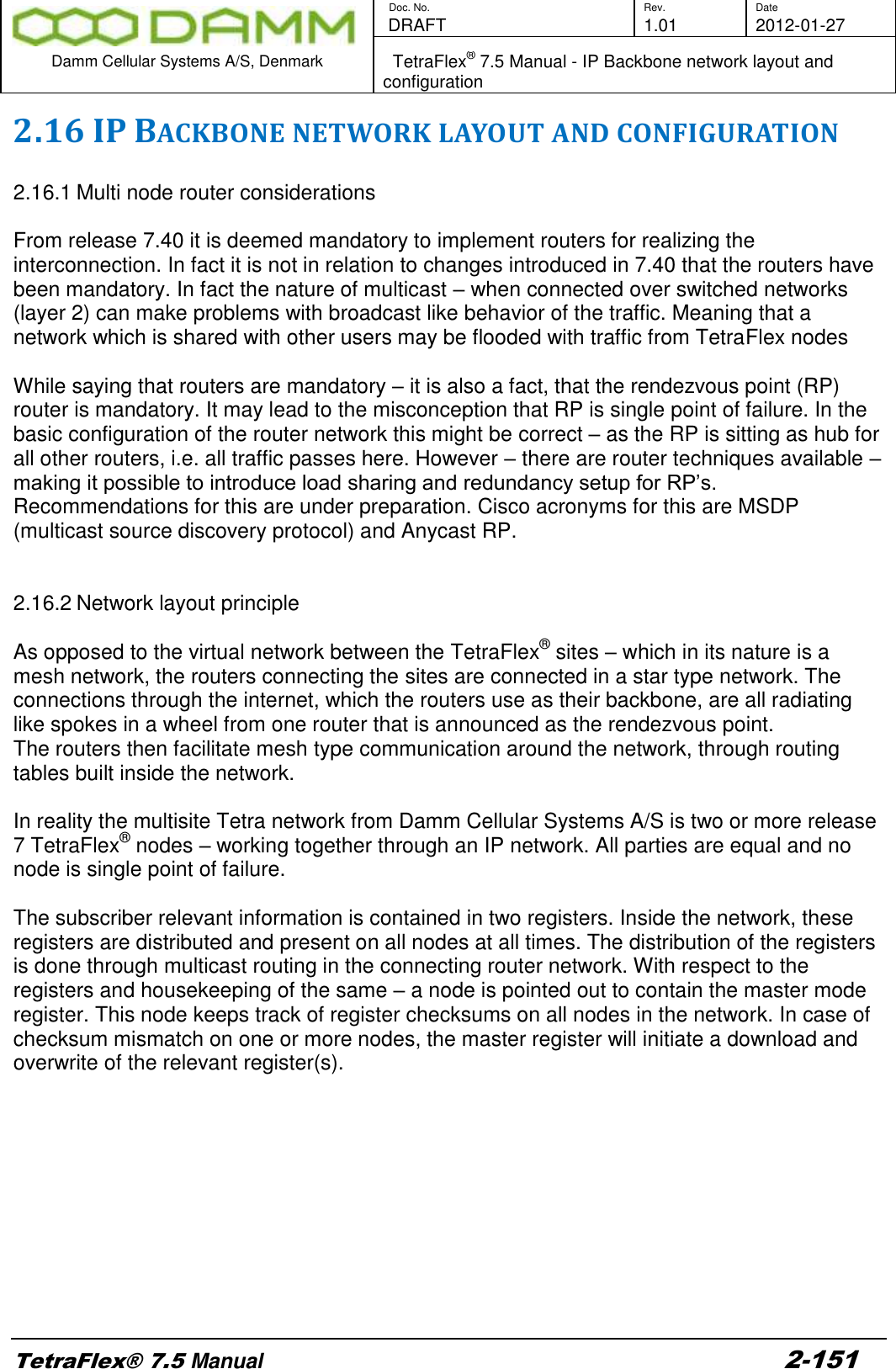
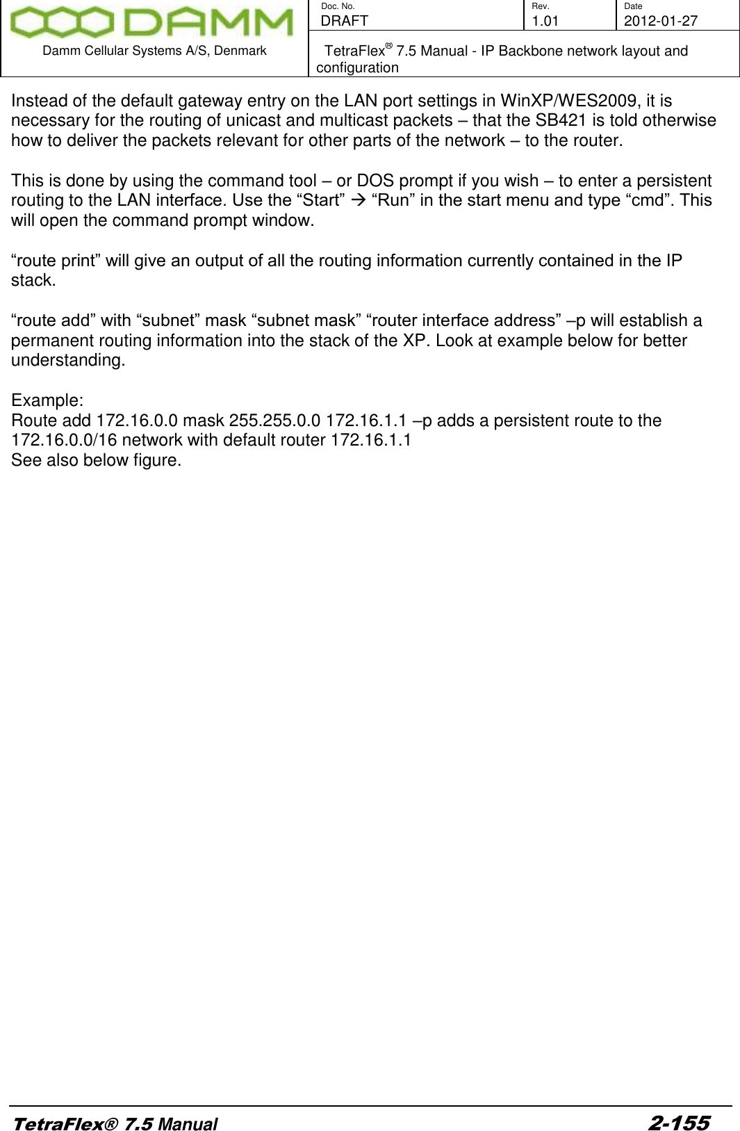
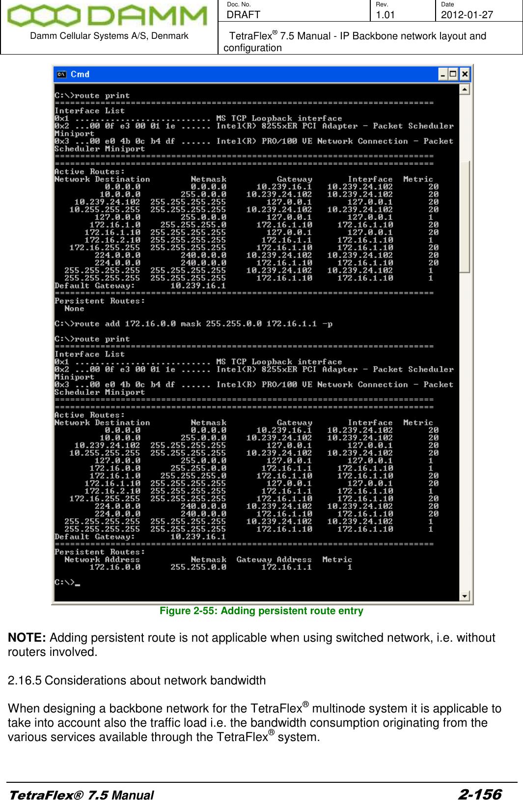
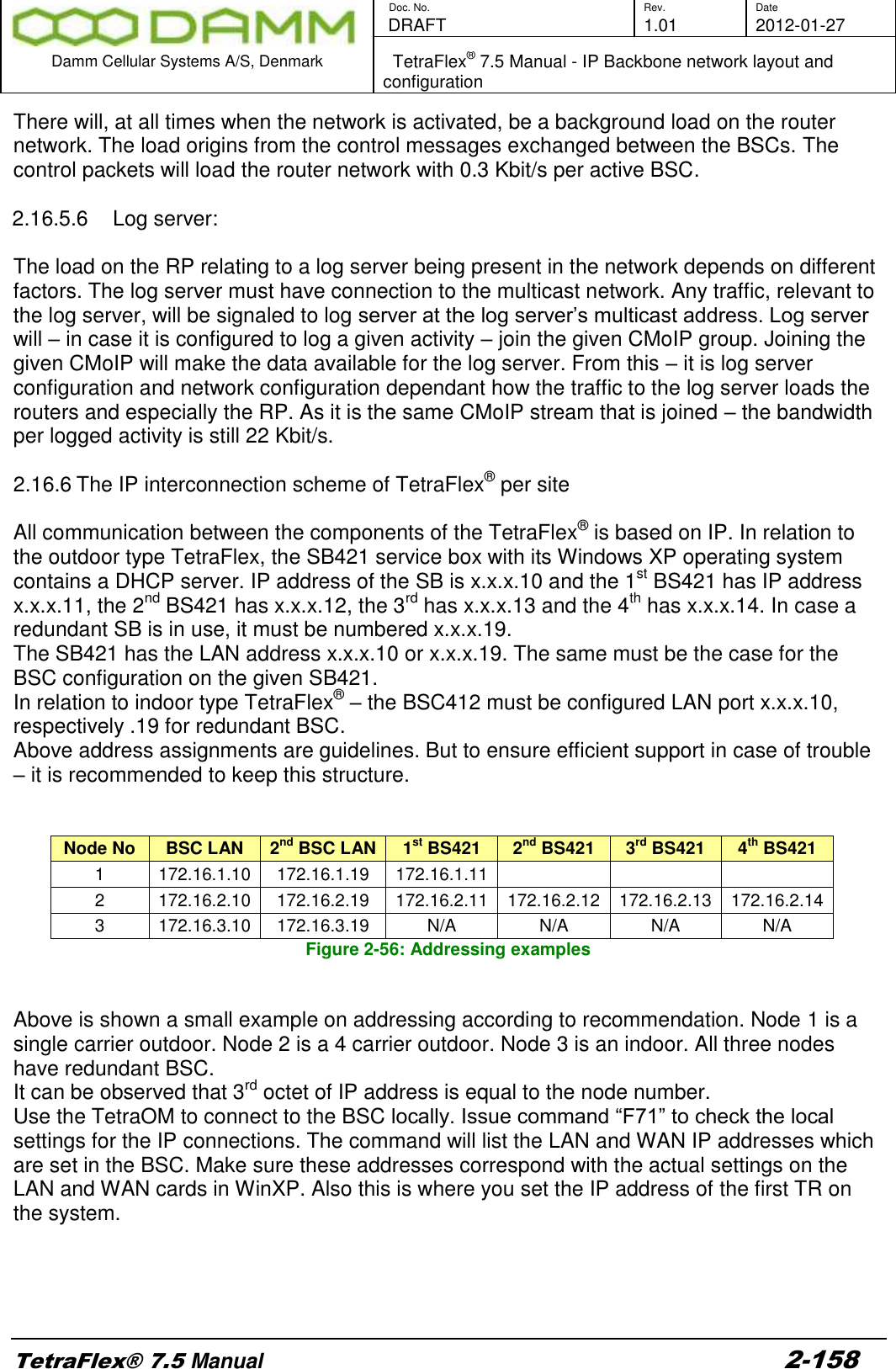
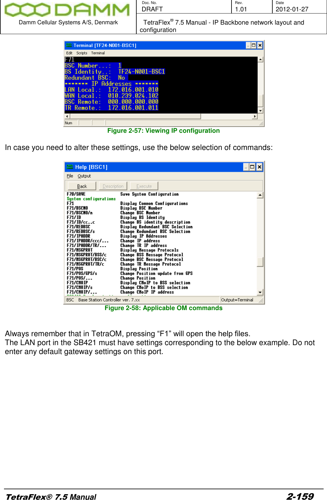
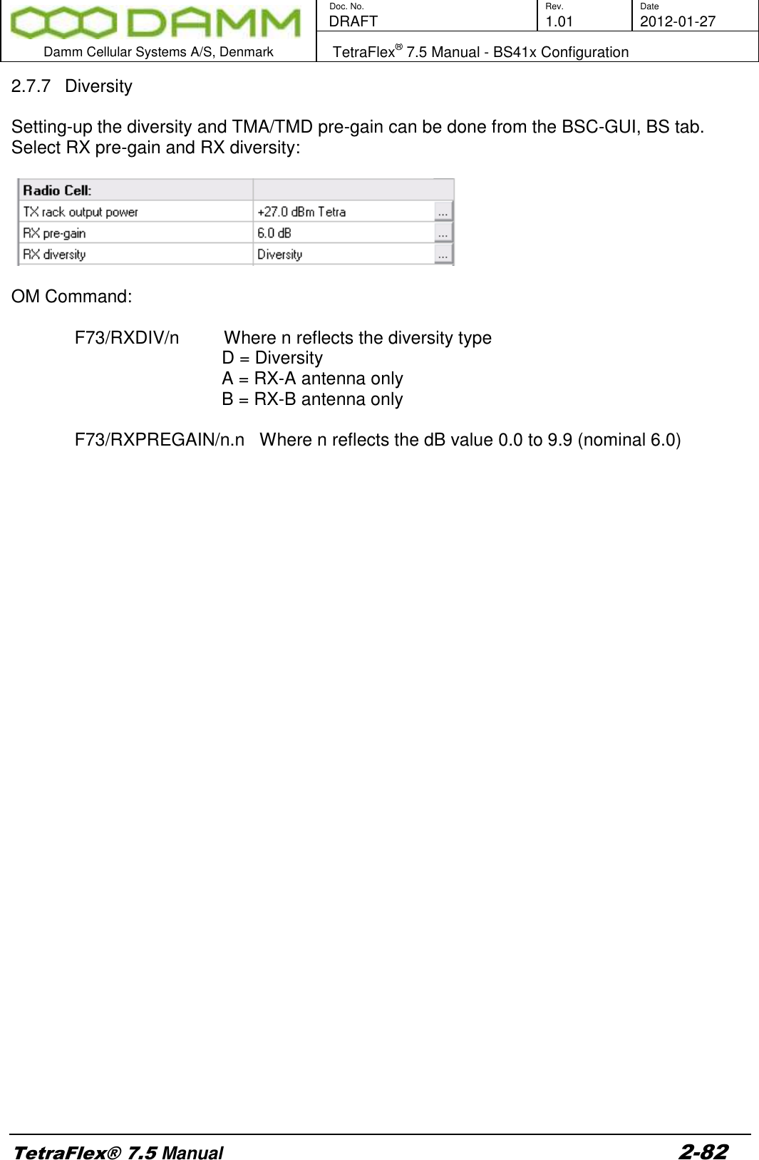
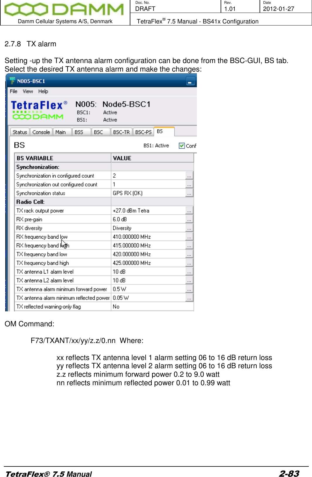
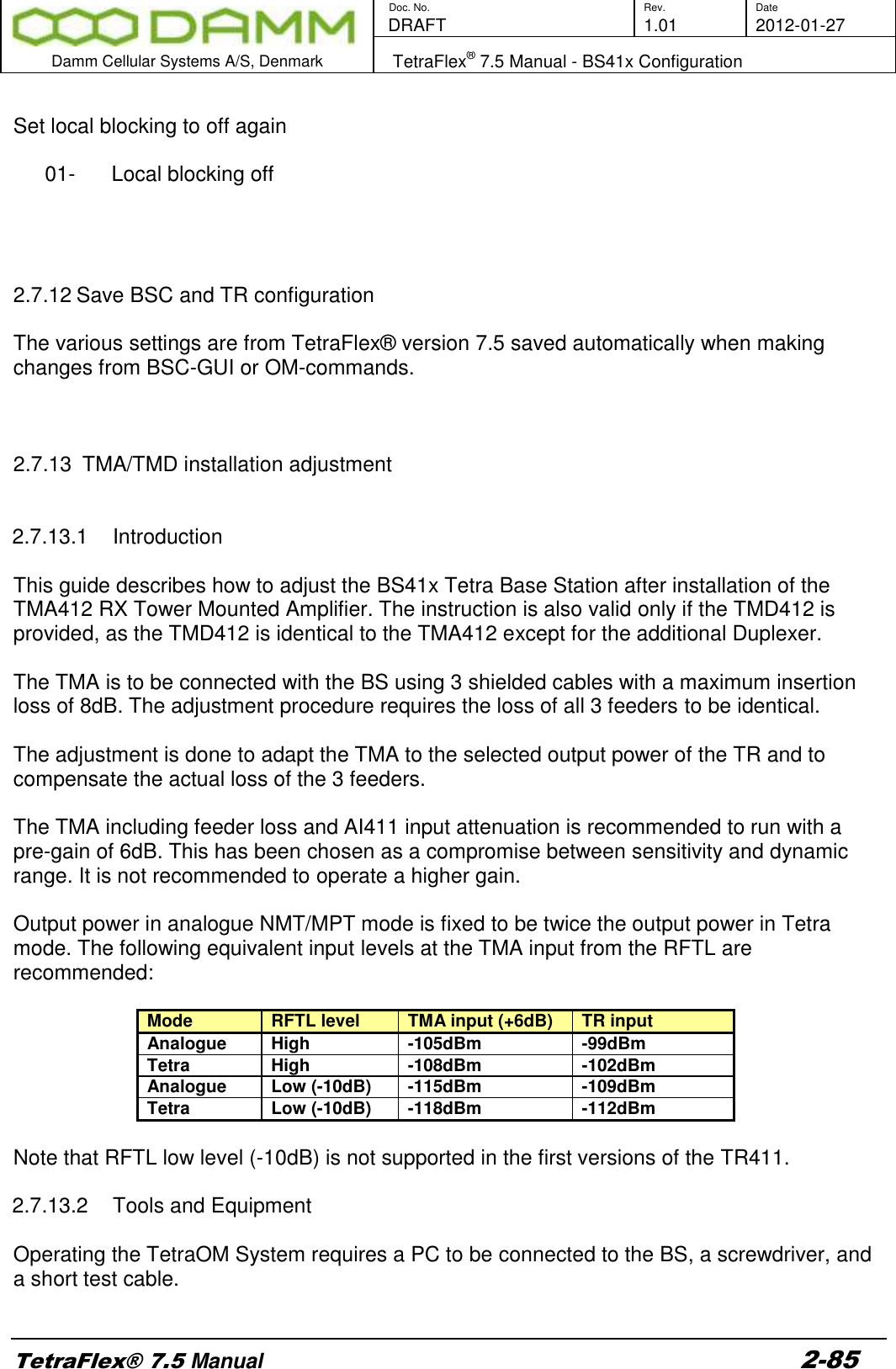
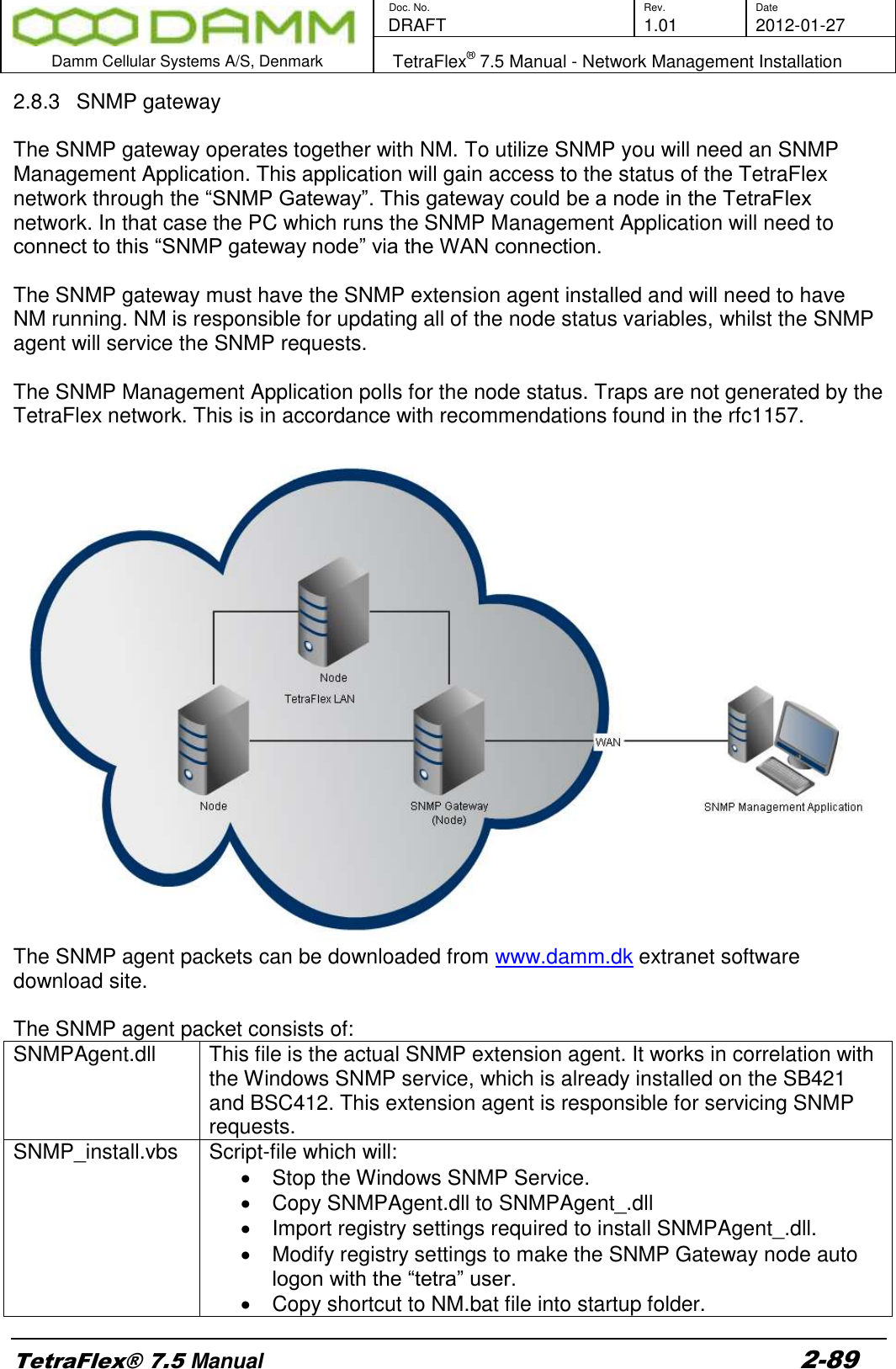
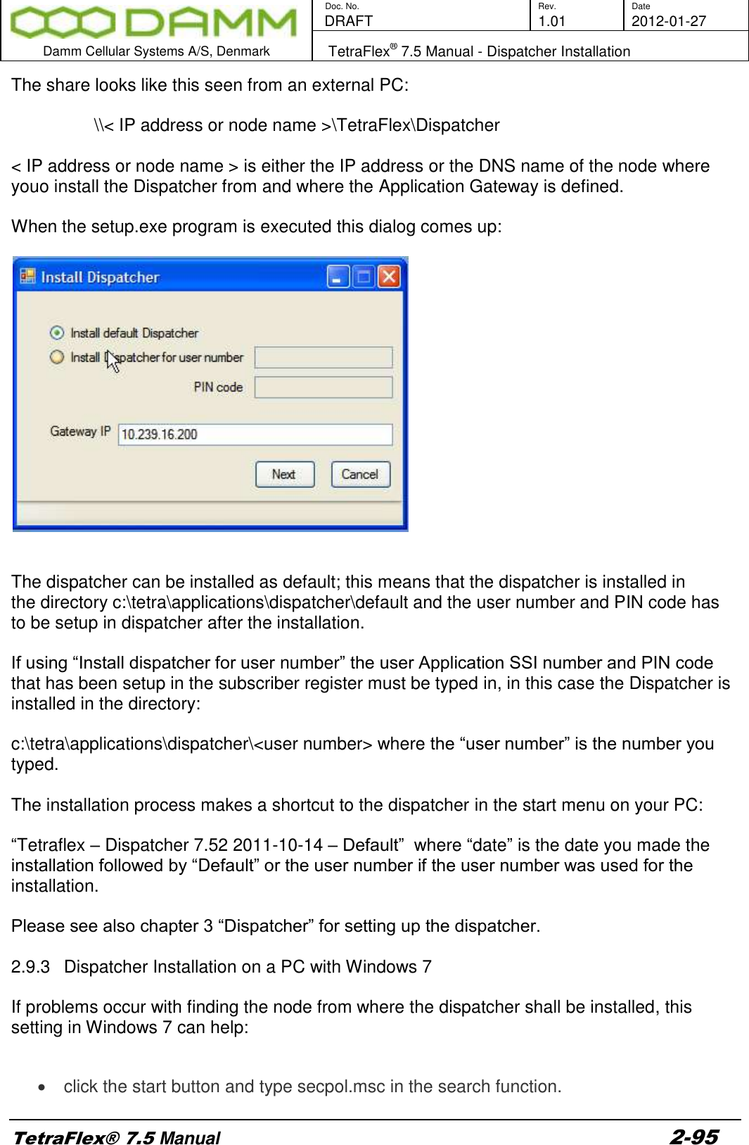
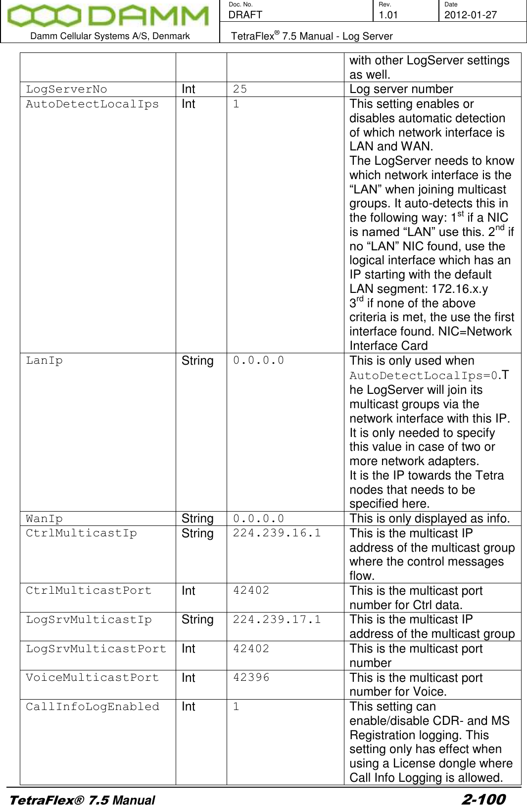
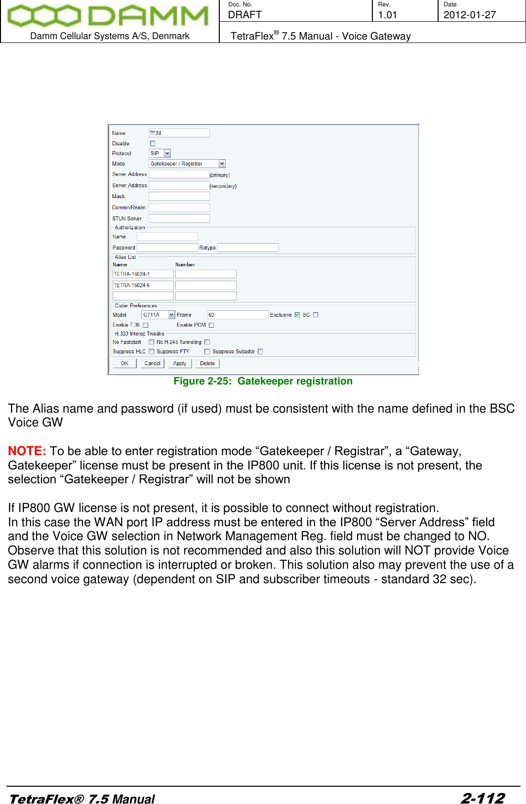
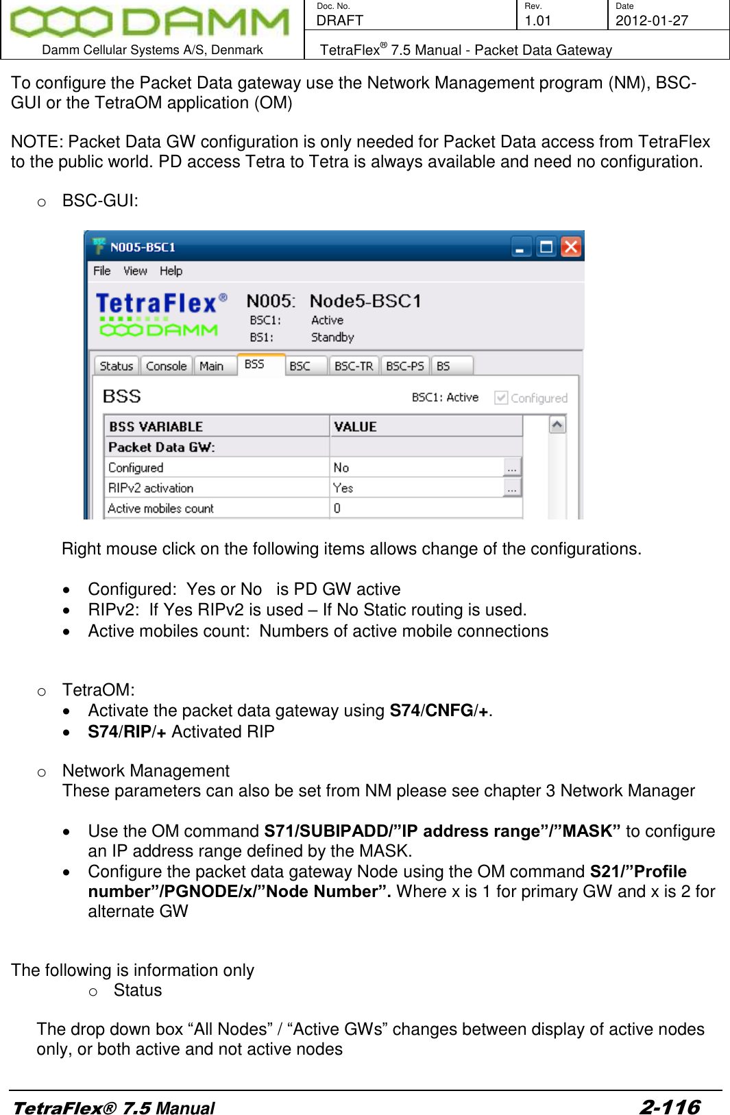
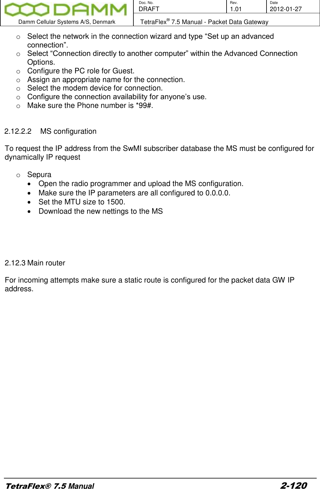
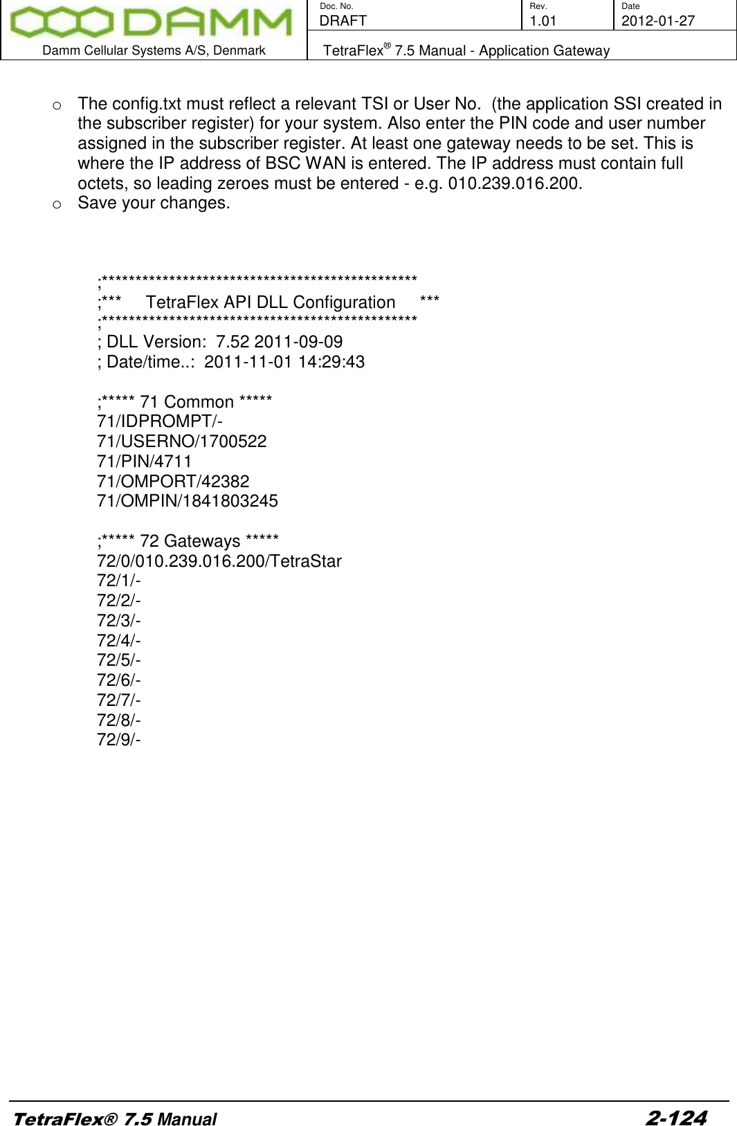
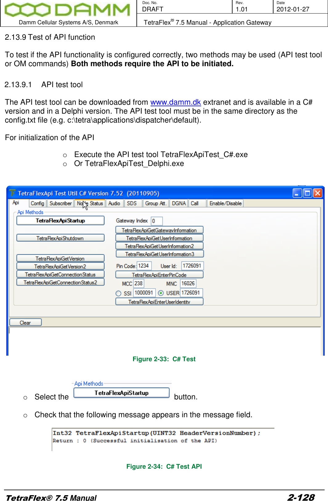
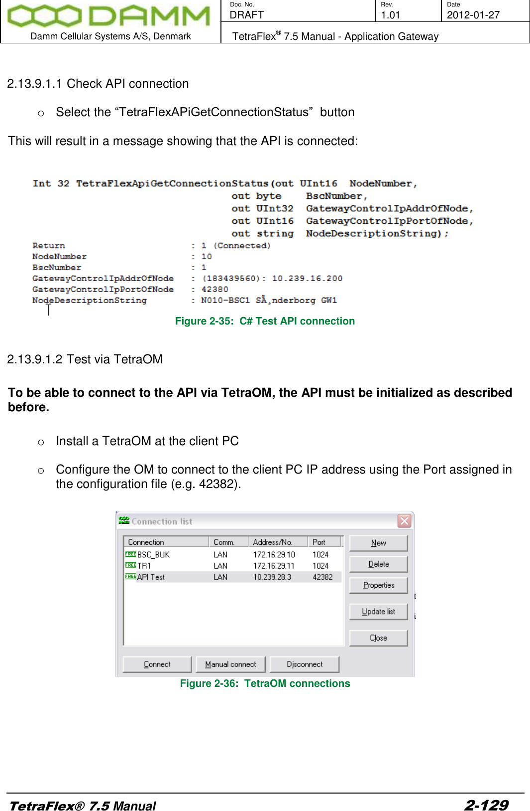
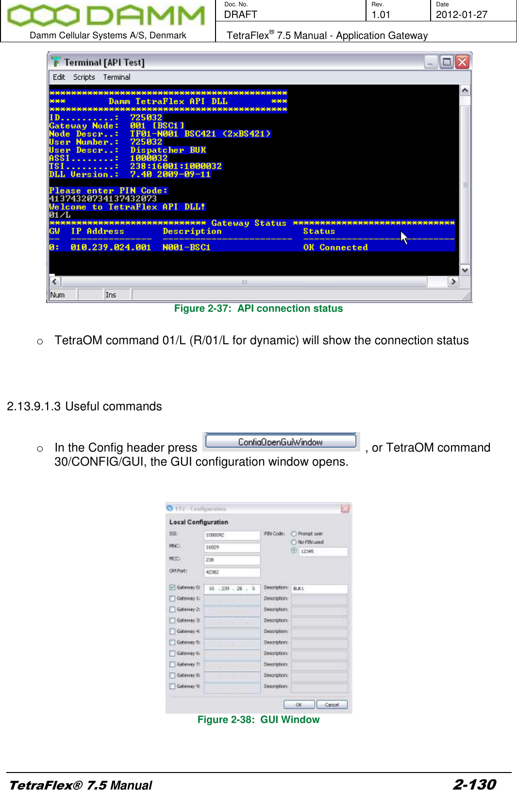
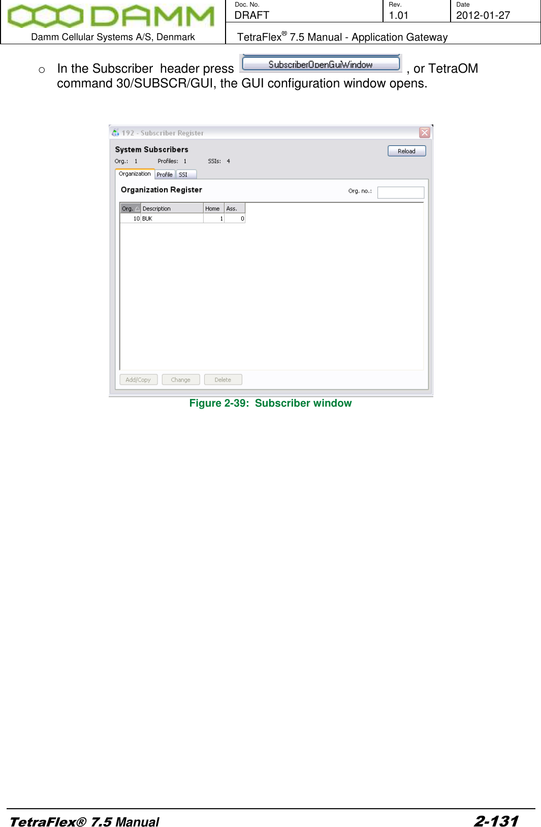
![Doc. No. Rev. Date DRAFT 1.01 2012-01-27 Damm Cellular Systems A/S, Denmark TetraFlex® 7.5 Manual - BS41x Configuration TetraFlex® 7.5 Manual 2-81 Setting the desired TX power level for all TR41x use the BSC-GUI, BS-Tab select the TX rack output power: The setting is Tetra Mode output power at Rack TX Antenna connector. An insertion loss of the combiner system of 4.0dB is assumed. If the value is lower or higher than the TR412 limits, the TR412 will set the power to the minimum or maximum power respectively. If set to Disabled (Controlled by TR412) the output is set to 0 Ant. conn. Tetra Power TR412 Power Standard TR412 +26.0dBm to +40.0dBm 1.0W to 25.0W High power TR412 +30.0dBm to +44.0dBm 2.5W to 62.5W OM Command: H73/TXPWR/+nn.n -Change TX output power (at Rack TX connector) nn.n: Output power (26.0..44.0 [dBm]), 00.0: Disabled (controlled of TR412 setting)](https://usermanual.wiki/Damm-Cellular-Systems-A-S/104012.User-manual-2/User-Guide-1739424-Page-11.png)
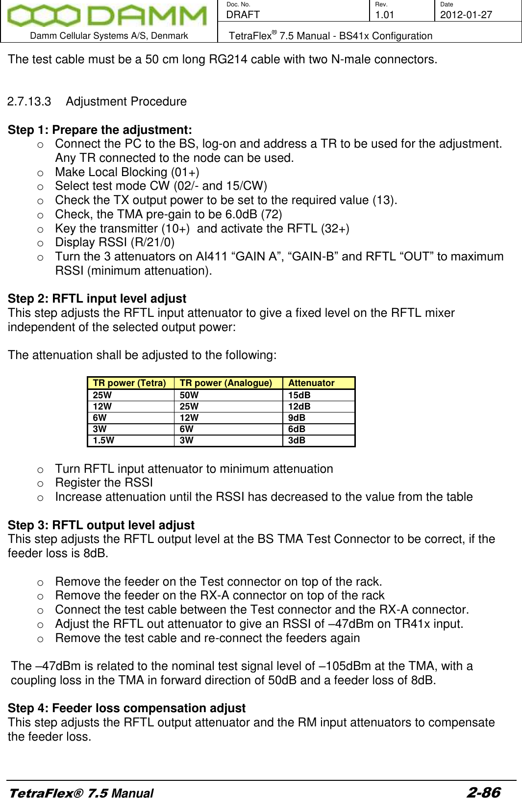
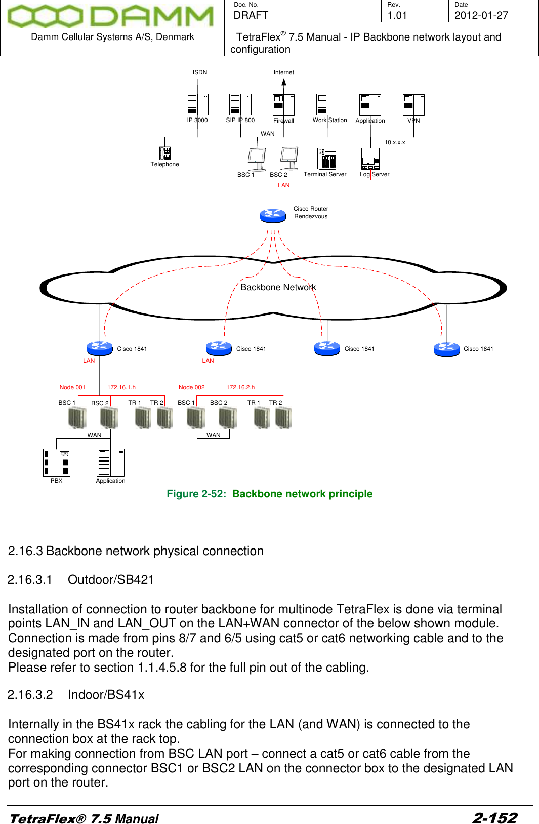
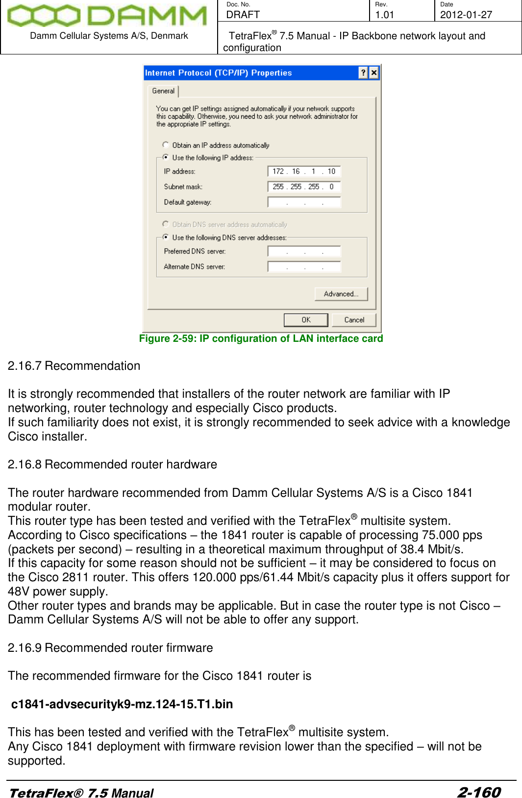
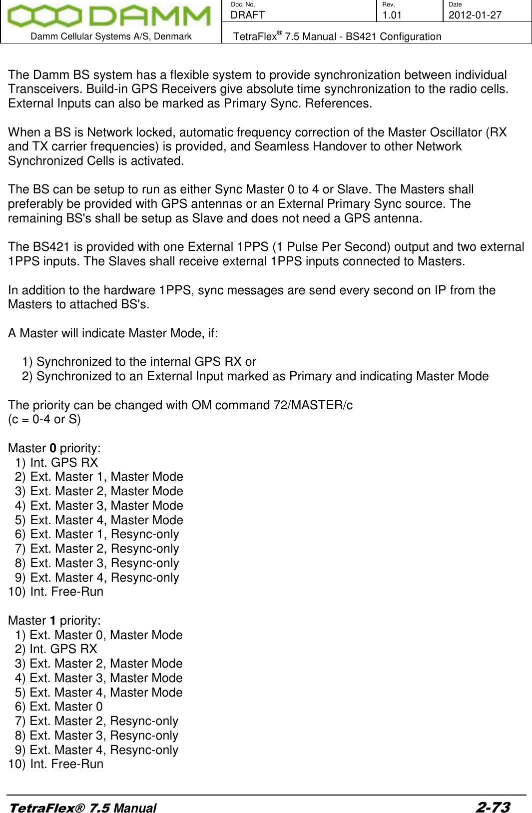
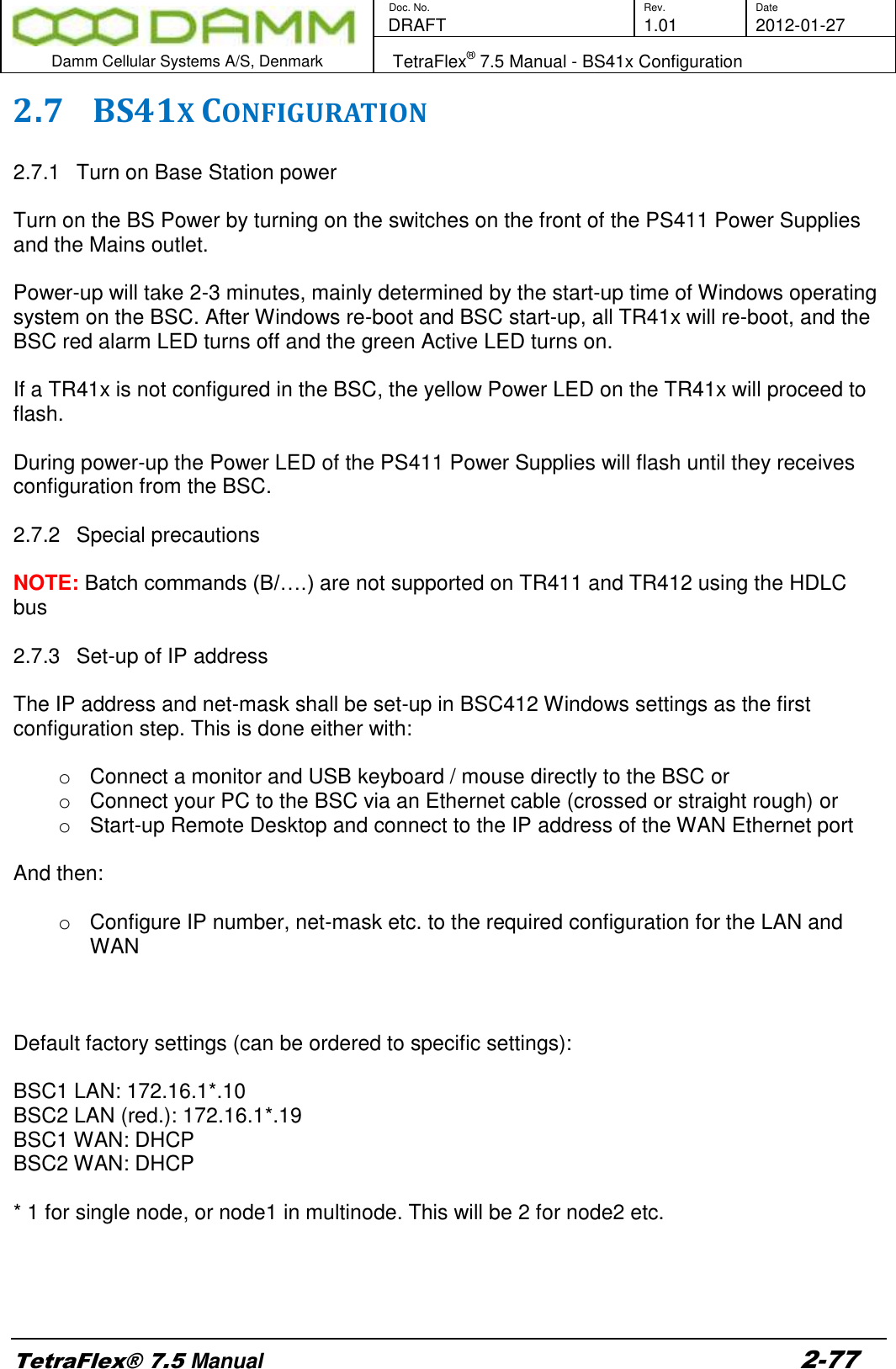
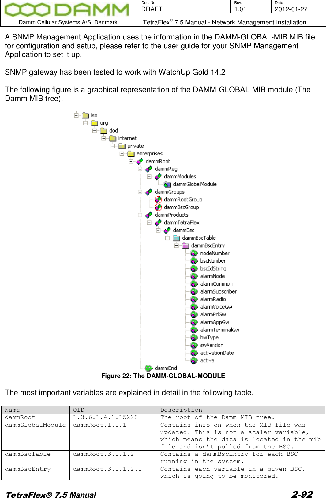
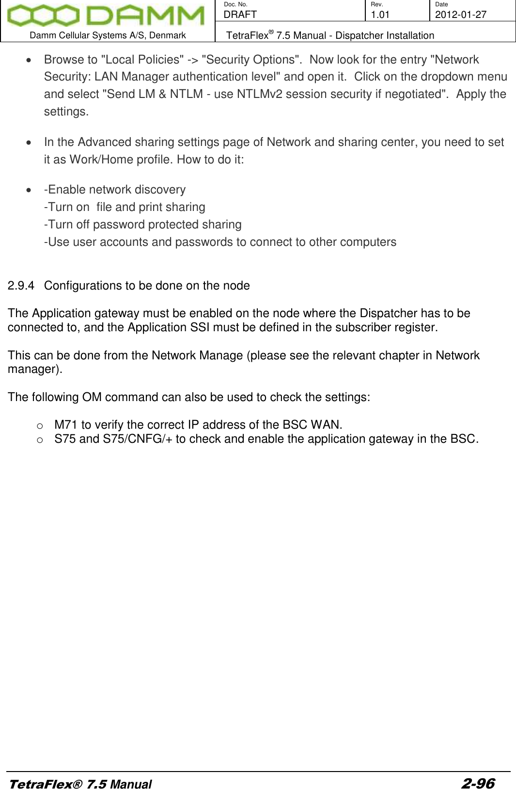
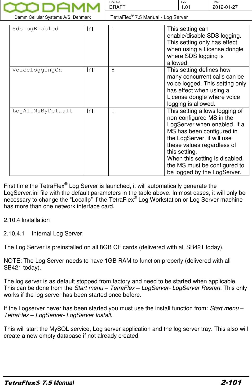
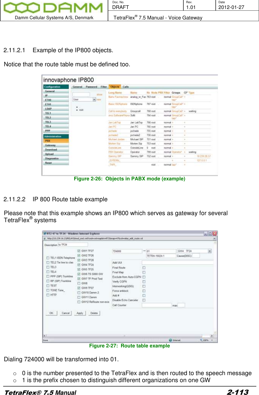
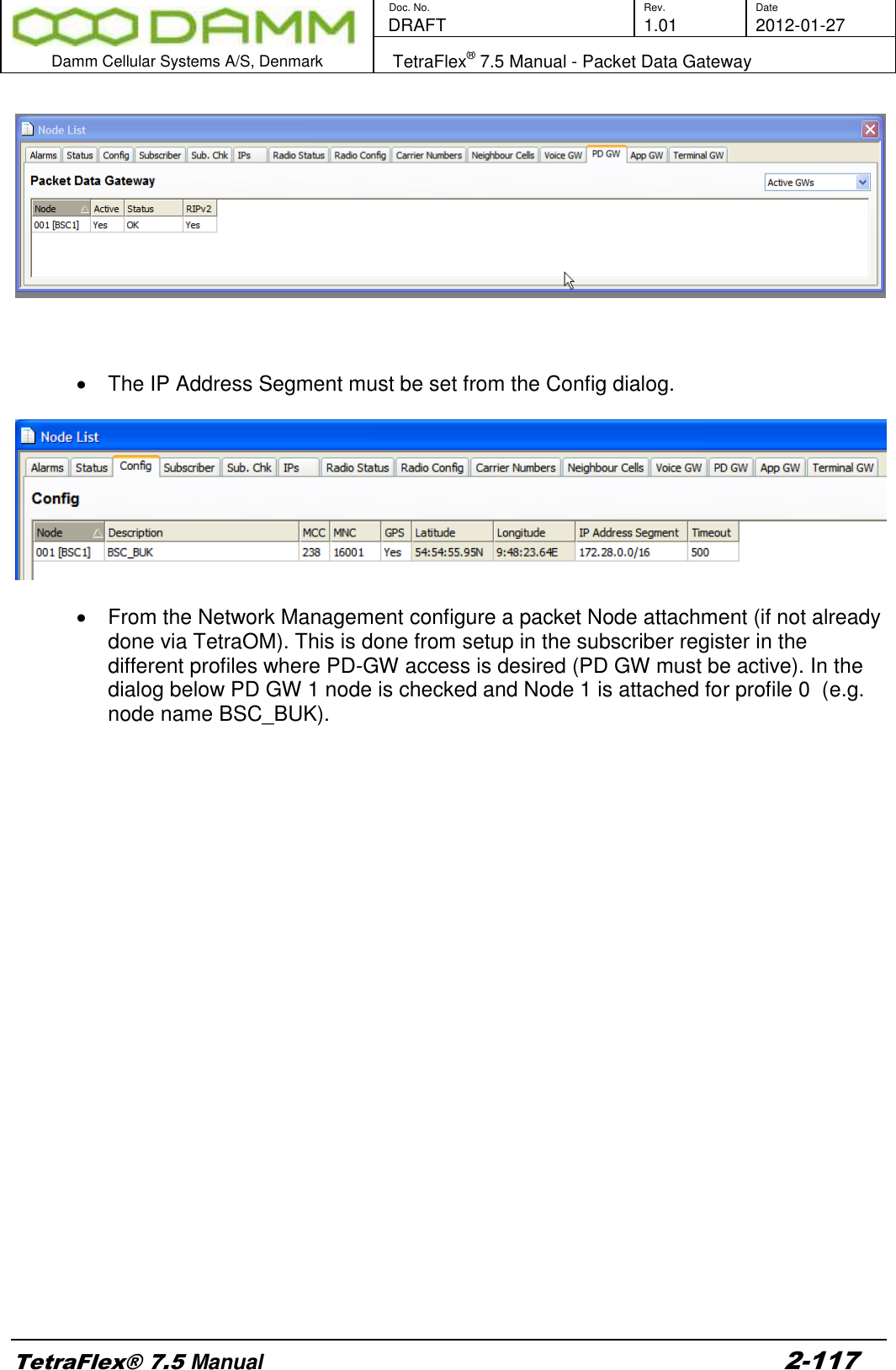
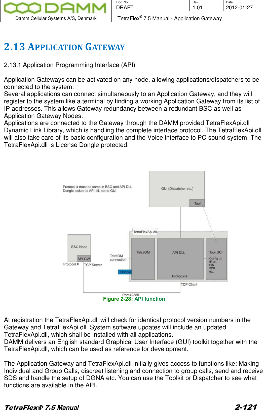
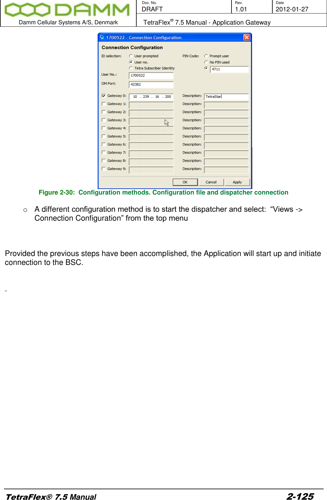
![Doc. No. Rev. Date DRAFT 1.01 2012-01-27 Damm Cellular Systems A/S, Denmark TetraFlex® 7.5 Manual - Network Management Installation TetraFlex® 7.5 Manual 2-90 Start Windows SNMP Service. SNMPInstall.reg Registry file containing registry settings necessary to install the SNMP extension dll. The settings in this file will be imported by the SNMP_Install.vbs file. NM.exe Network Management application. NM is regularly updating the BSC variables, so that the extension agent is able to service the SNMP request with the latest info. Network Management.lnk Shortcut to the NM.bat file located under C:\Tetra\Active\Pgm\NM. DAMM-GLOBALMIB. Mib Damm MIB tree 2.8.3.1 SNMP installation To install the SNMP agent on the SB421 or BSC412 complete the following steps: 1. Copy “DAMM-GLOBAL-MIB.mib” into the documentation folder of the BSC “C:\Tetra\Active\Doc\”. 2. Copy SNMPAgent.dll, SNMP_install.vbs, SNMPInstall.reg, NM.exe and Network Management.lnk to the SNMP gateway node. The files should be placed in C:\Tetra\Active\Pgm\NM. 3. Run the SNMP_install.vbs file to install the SNMP extension dll and registry settings. 4. Start-up the Network Management application (NM). NM should be set to auto start to start-up automatically when the computer is restarted. The SNMP gateway will not operate without the NM. 2.8.3.2 SNMP Manually PC installation If the Damm SNMP agent is to be installed on a PC instead of a SB421 or BSC412, you will have to install the agent manually. To manually install the Damm SNMP agent do the following: 1. Make sure the Windows SNMP Service is installed on the PC. It can be installed via: “Control Panel” – “Add or remove programs” – “Add/Remove Windows components” – “Management and monitoring tools” – “Simple Network Management Protocol”. 2. Copy SNMPAgent.dll, NM.exe and Network Management.lnk to the PC. The files should be placed at C:\Tetra\Active\Pgm\NM. 3. Copy the SNMPAgent.dll, and rename the copy “SNMPAgent_.dll”. 4. Install the SNMPAgent_.dll by entering the following settings into the registry: HKEY_LOCAL_MACHINE\SYSTEM\CurrentControlSet\Services\SNMP\Parameters\ExtensionAgents] "TetraFlexSNMP"="SOFTWARE\\SNMP\\CurrentVersion" [HKEY_LOCAL_MACHINE\SOFTWARE\SNMP\CurrentVersion] "Pathname"="C:\\Tetra\\Active\\Pgm\\NM\\SNMPAgent_.dll" 5. Make the PC login automatically upon boot, by entering the following settings into the registry (exchange DefaultUserName and DefaultPassword with the correct username and password):](https://usermanual.wiki/Damm-Cellular-Systems-A-S/104012.User-manual-2/User-Guide-1739424-Page-20.png)
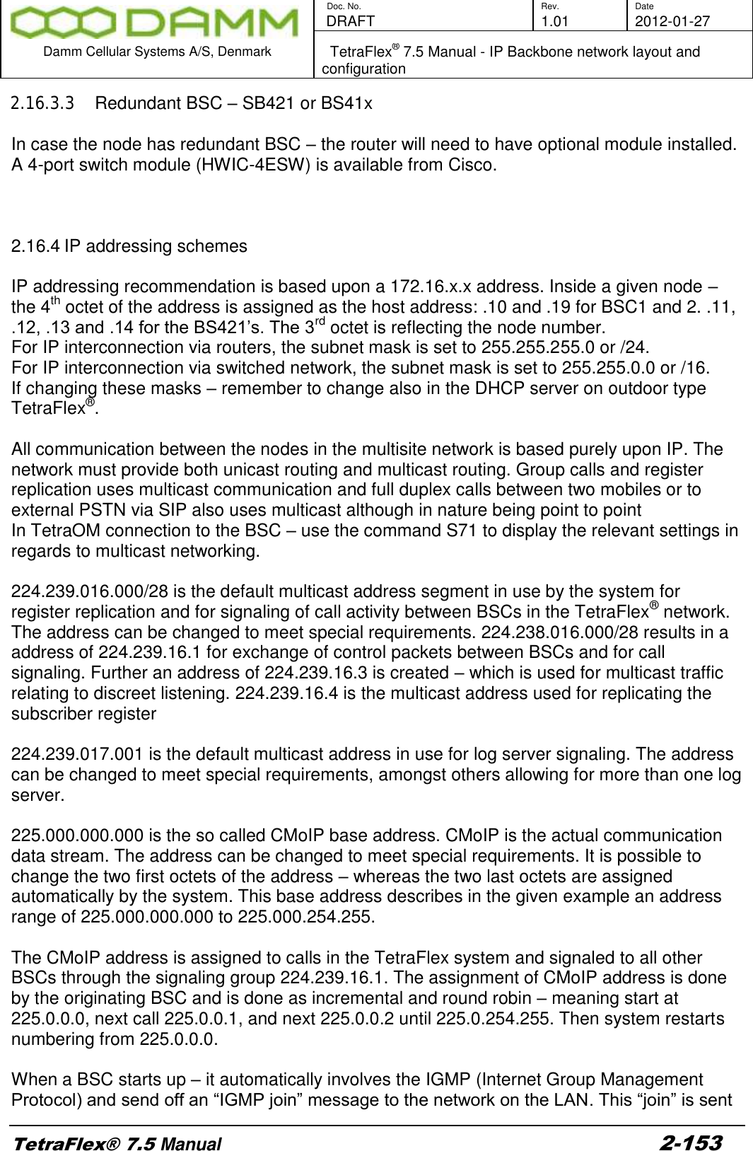
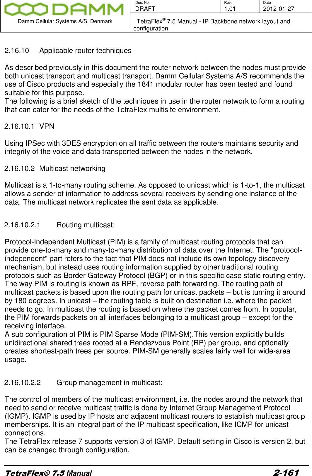
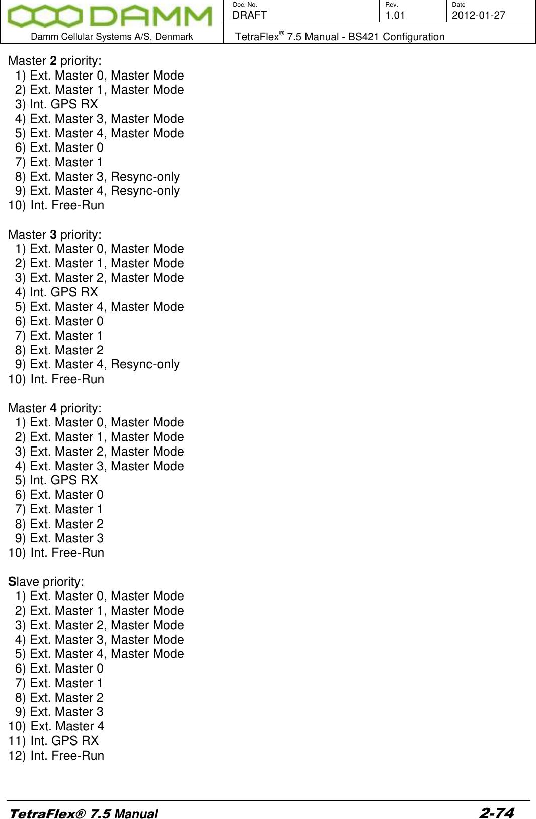
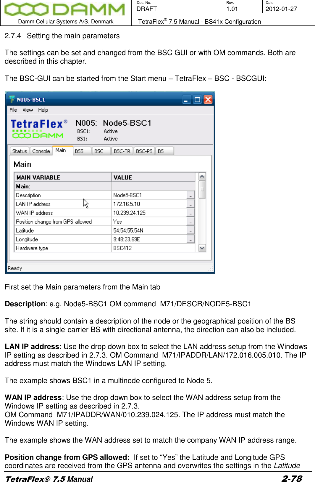
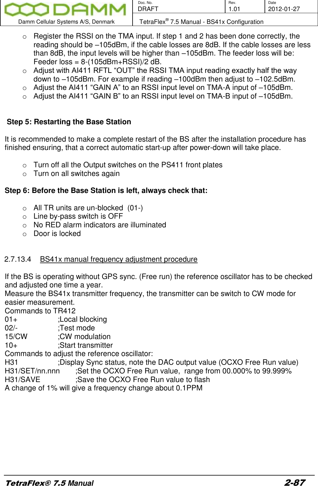
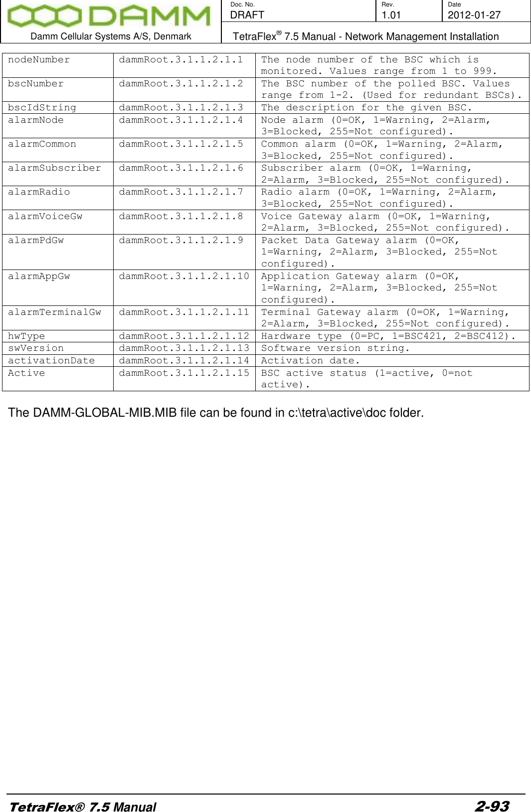
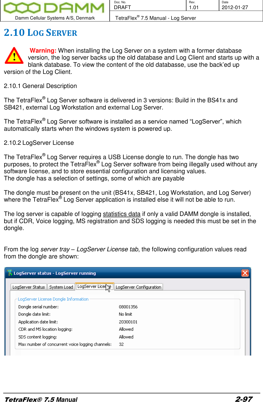
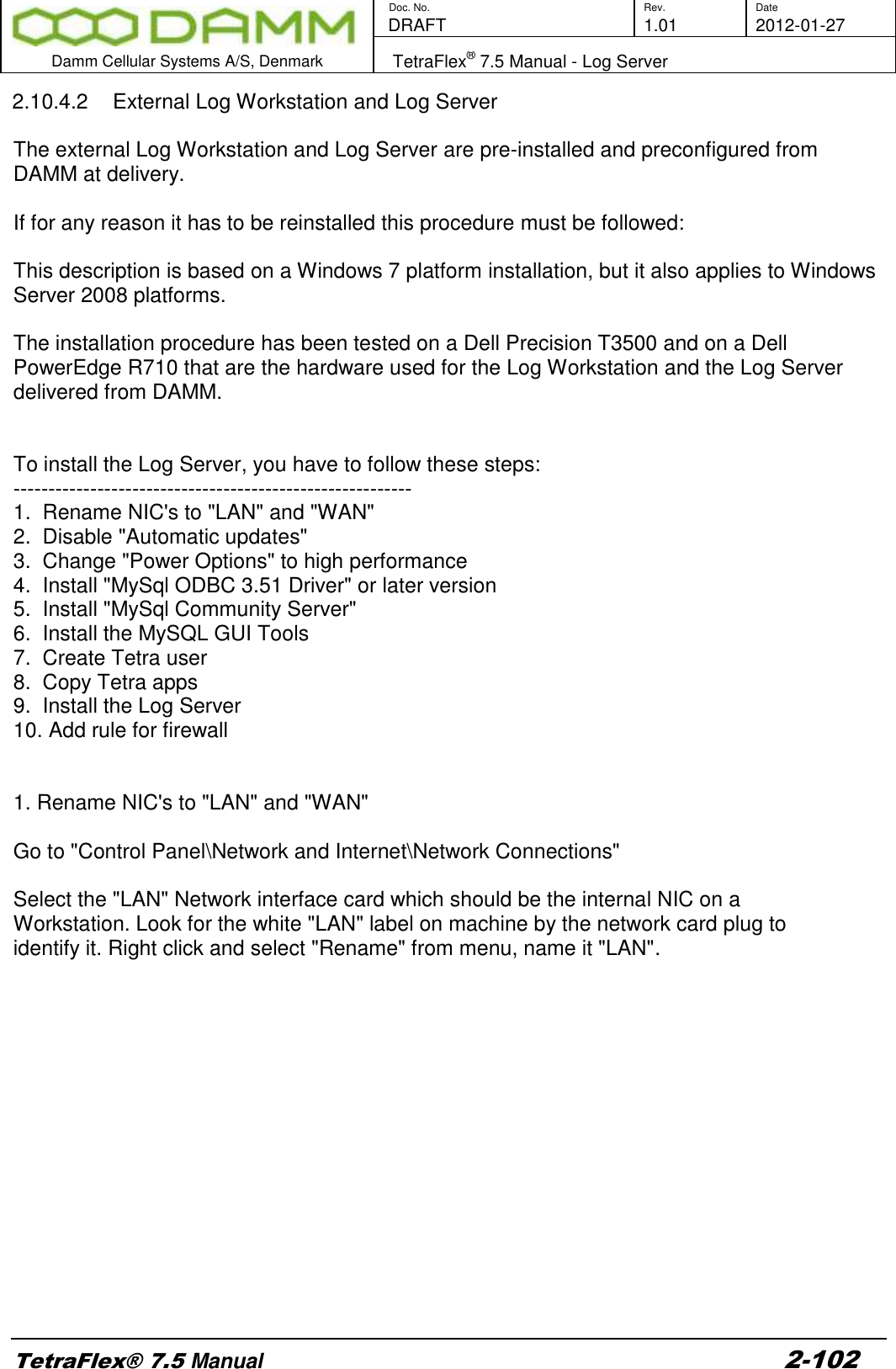
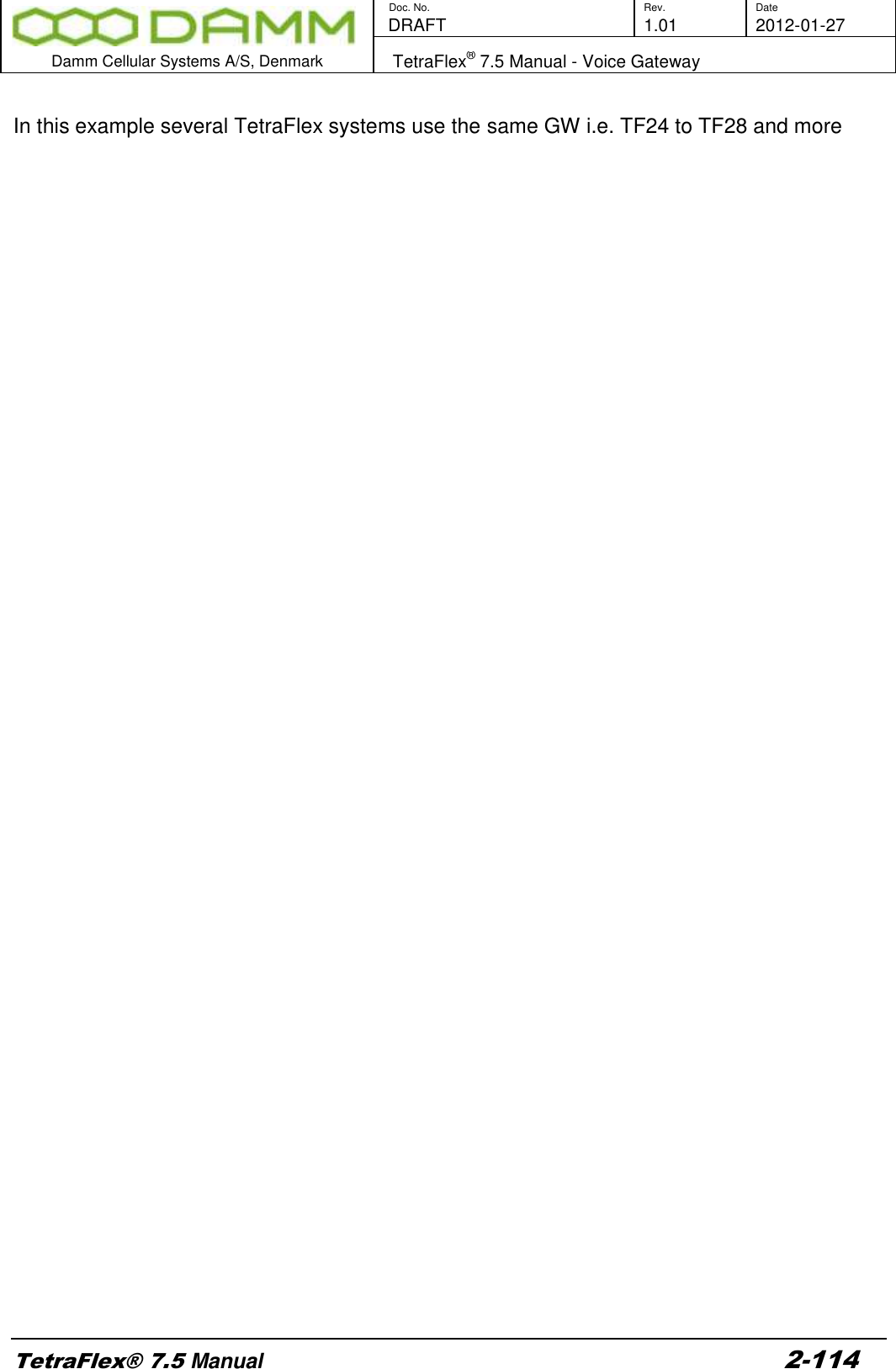
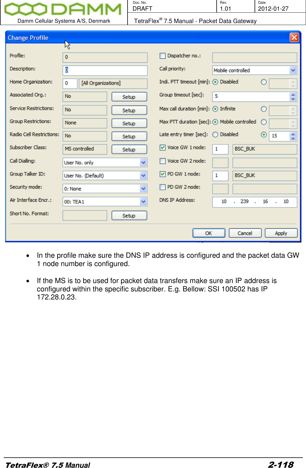
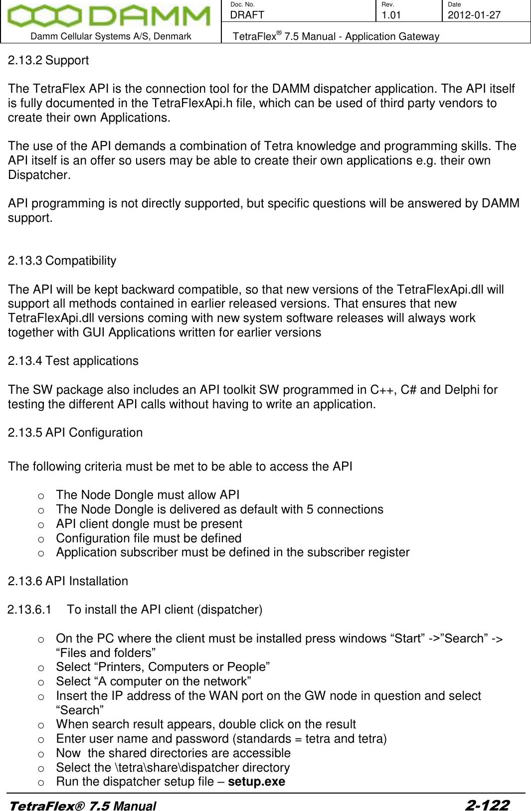
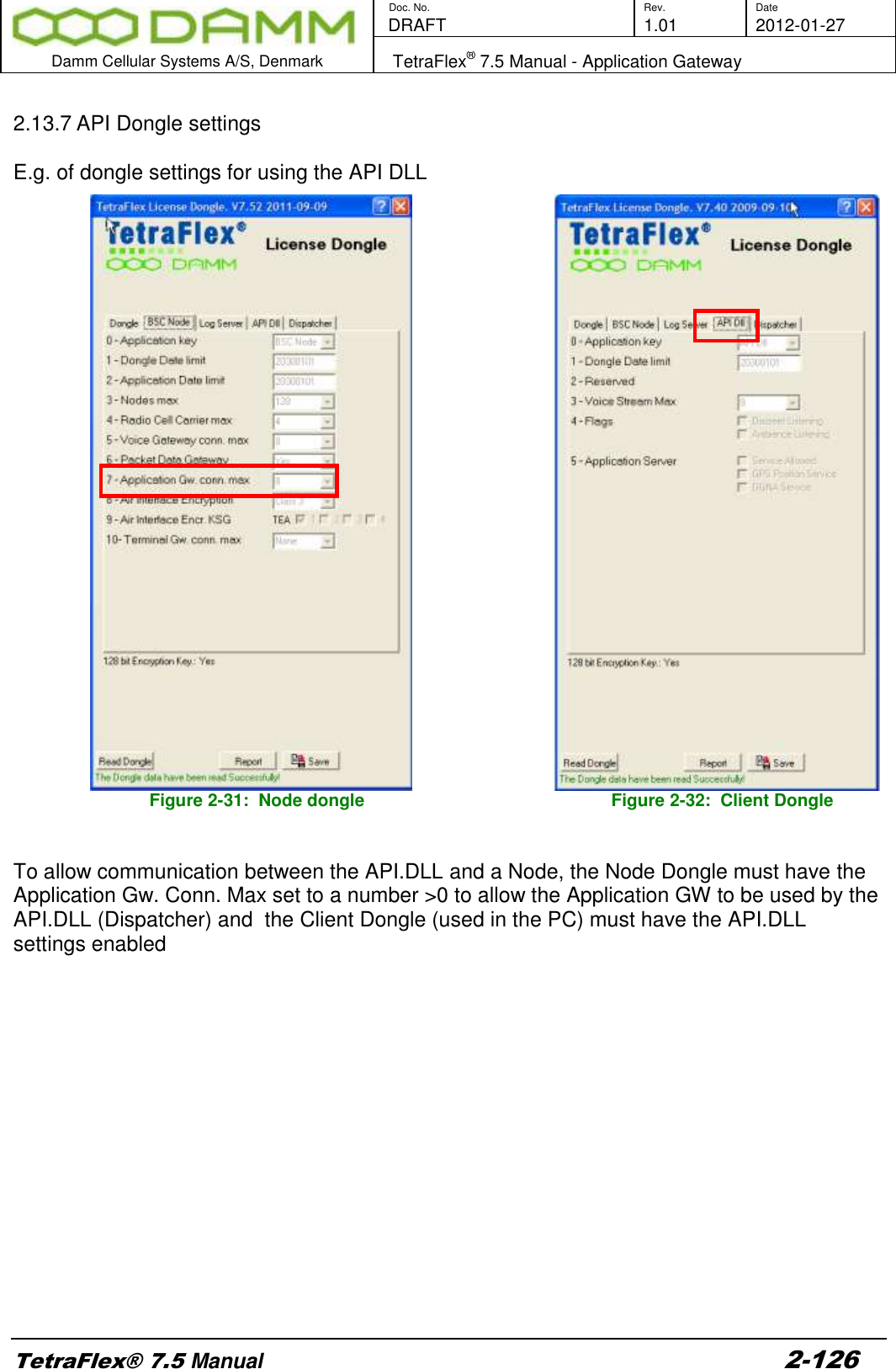
![Doc. No. Rev. Date DRAFT 1.01 2012-01-27 Damm Cellular Systems A/S, Denmark TetraFlex® 7.5 Manual - Network Management Installation TetraFlex® 7.5 Manual 2-91 [HKEY_LOCAL_MACHINE\SOFTWARE\Microsoft\Windows NT\CurrentVersion\Winlogon] "AutoAdminLogon"="1" "DefaultUserName"="tetra" "DefaultPassword"="tetra" 6. Place the Network Management.lnk file in the startup folder to make the Network Management application startup automatically upon boot.. 7. Check the SNMP Security settings (start -> right click on ”my computer” -> manage -> Services and Applications -> Services -> SNMP Service -> Properties -> Security). These settings could be as shown in the example on the following figure: A more safe solution is to restrict the SNMP access by ticking ”Accept SNMP packets from the hosts” and add the Host name, IP or IPX address of the specific known hosts. 8. Restart the Windows SNMP Service. 9. Start the Network Management application. NM should be set to auto start-up to make it start-up automatically when the computer is restarted. The SNMP gateway will not work without the NM. 2.8.3.3 SNMP MIB Tree](https://usermanual.wiki/Damm-Cellular-Systems-A-S/104012.User-manual-2/User-Guide-1739424-Page-21.png)
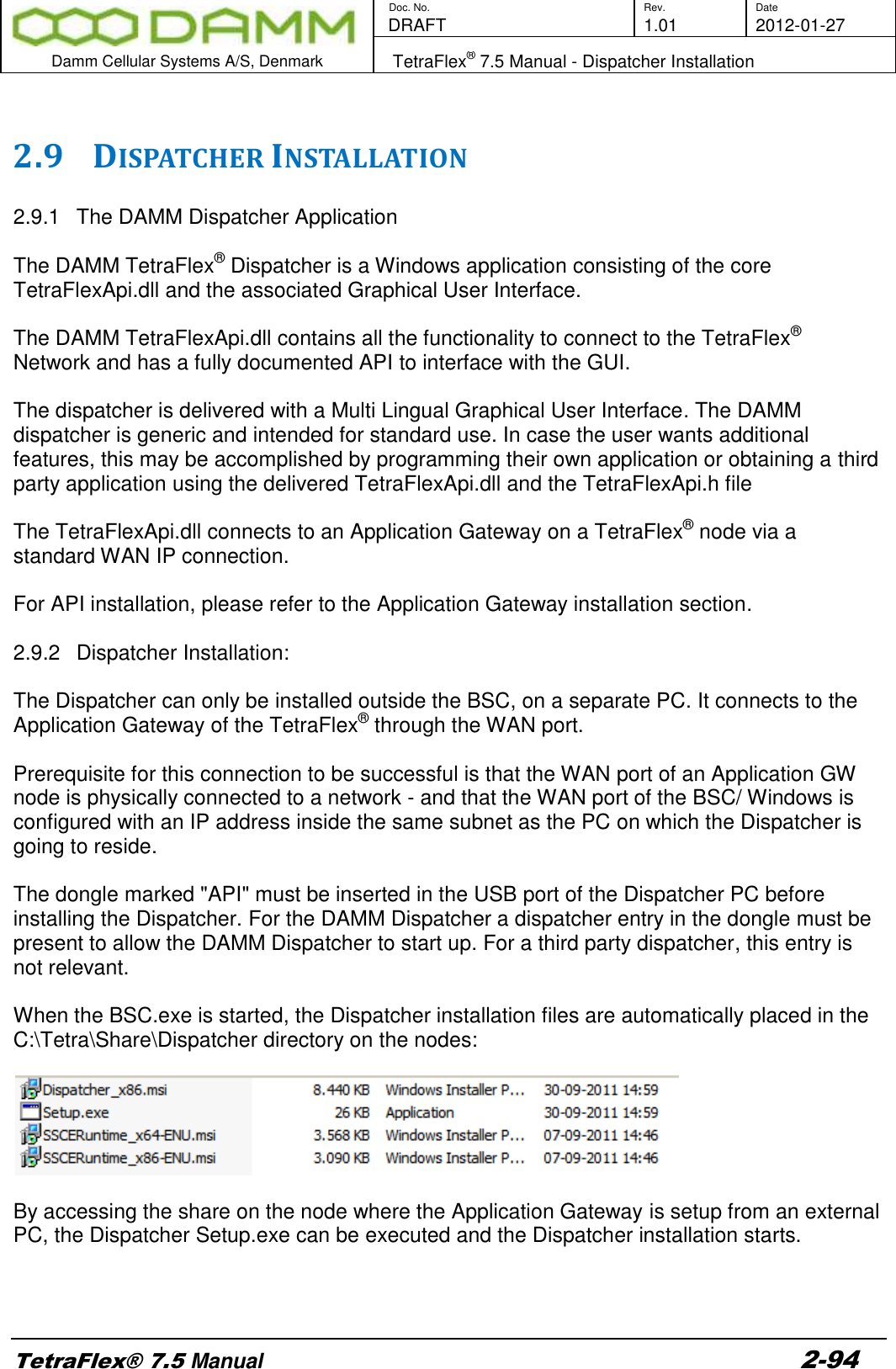
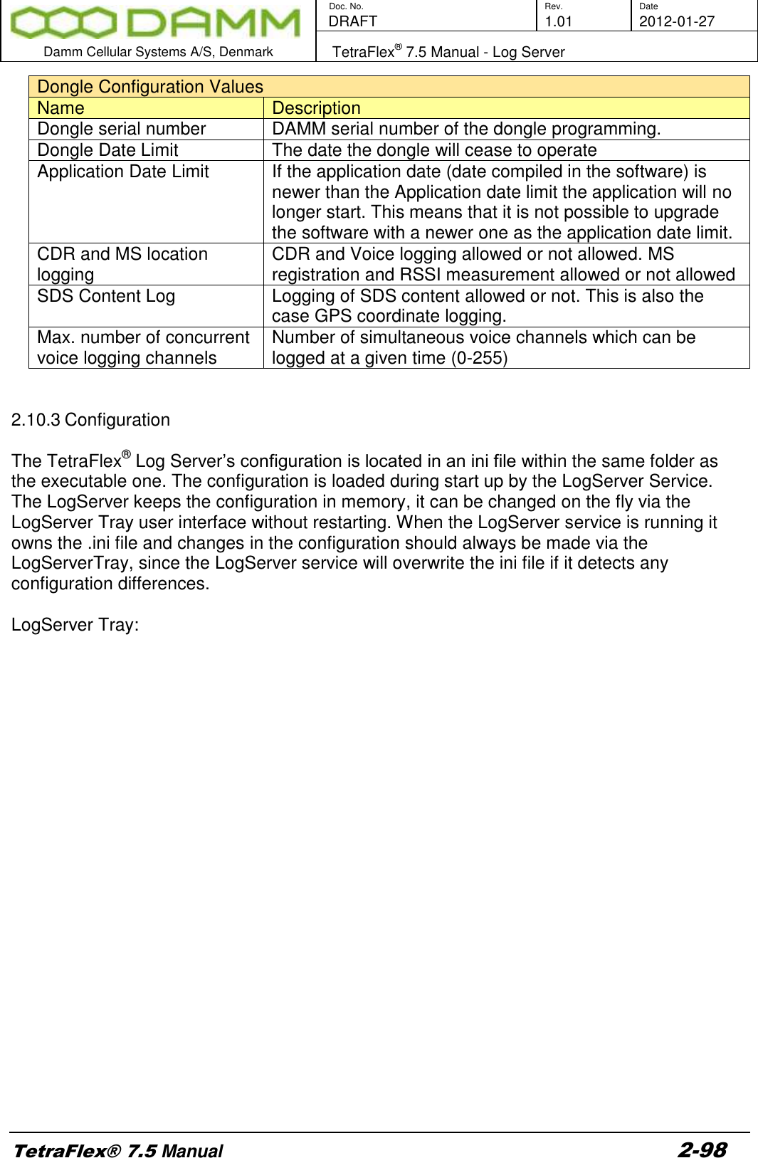
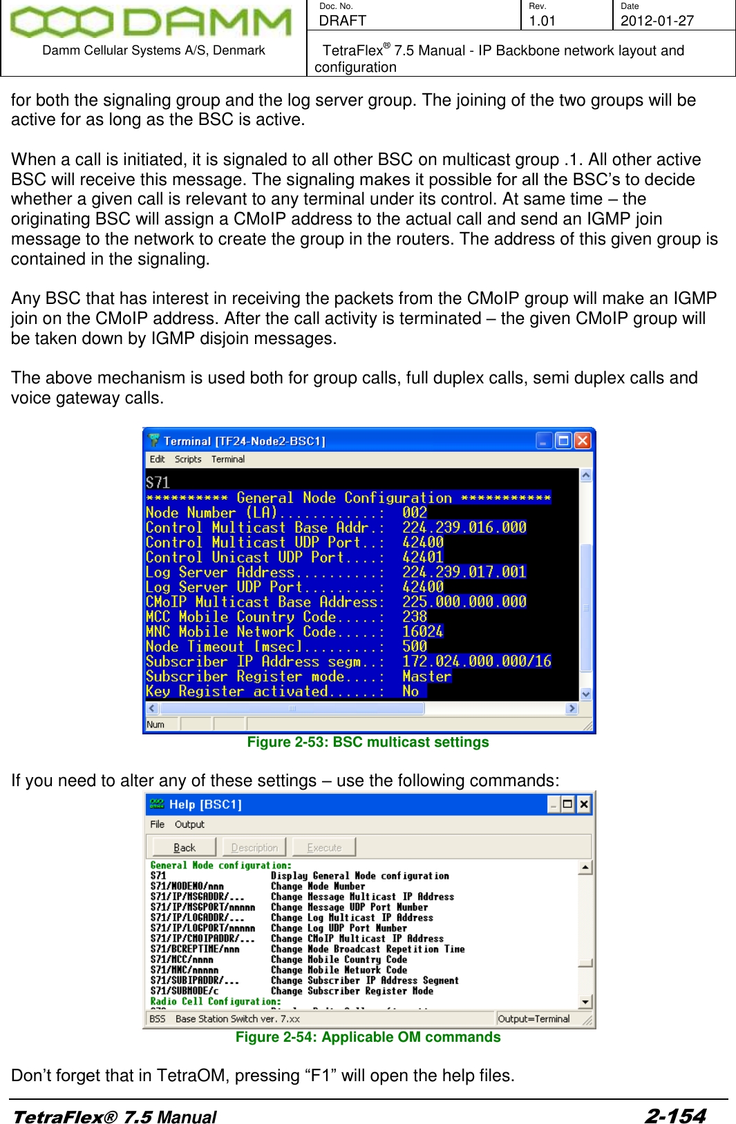
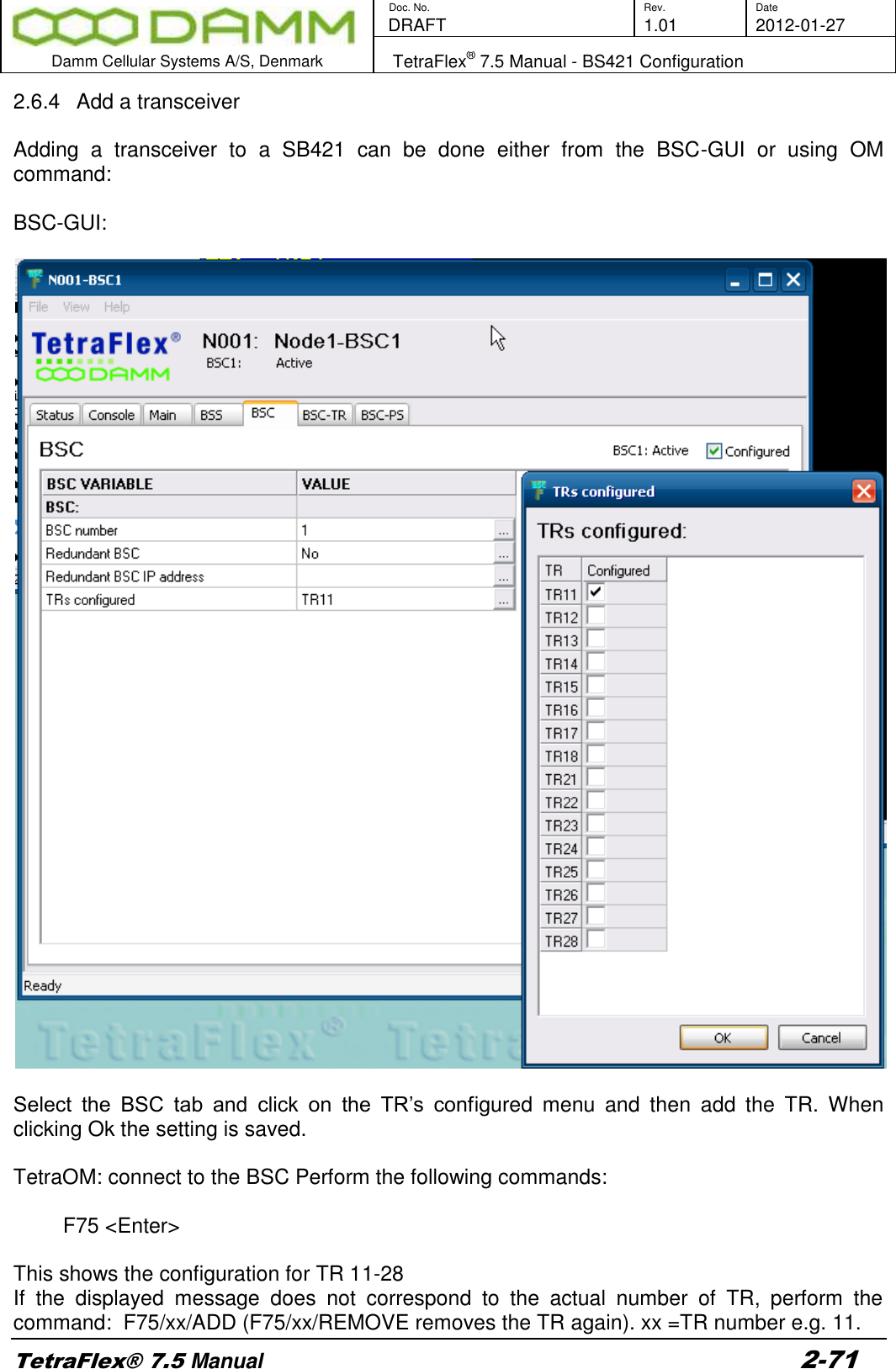
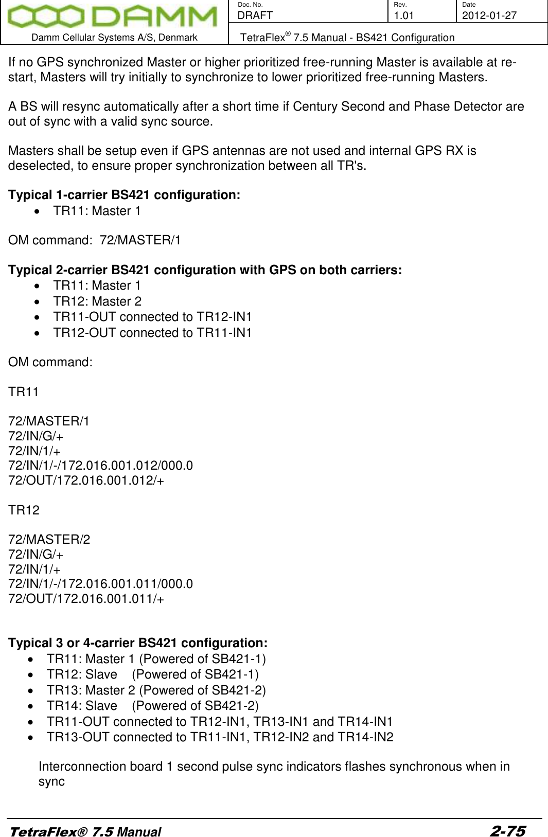
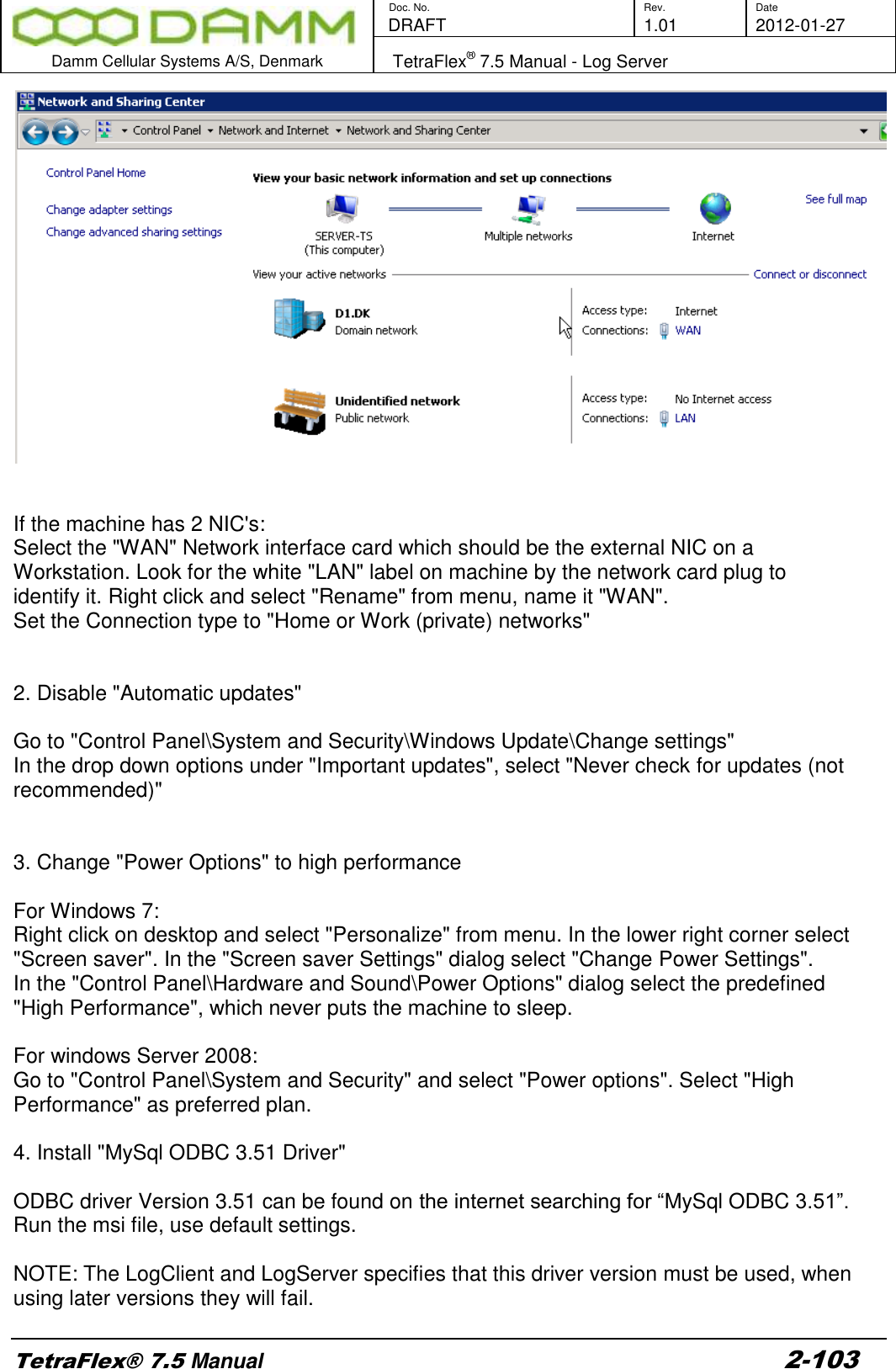
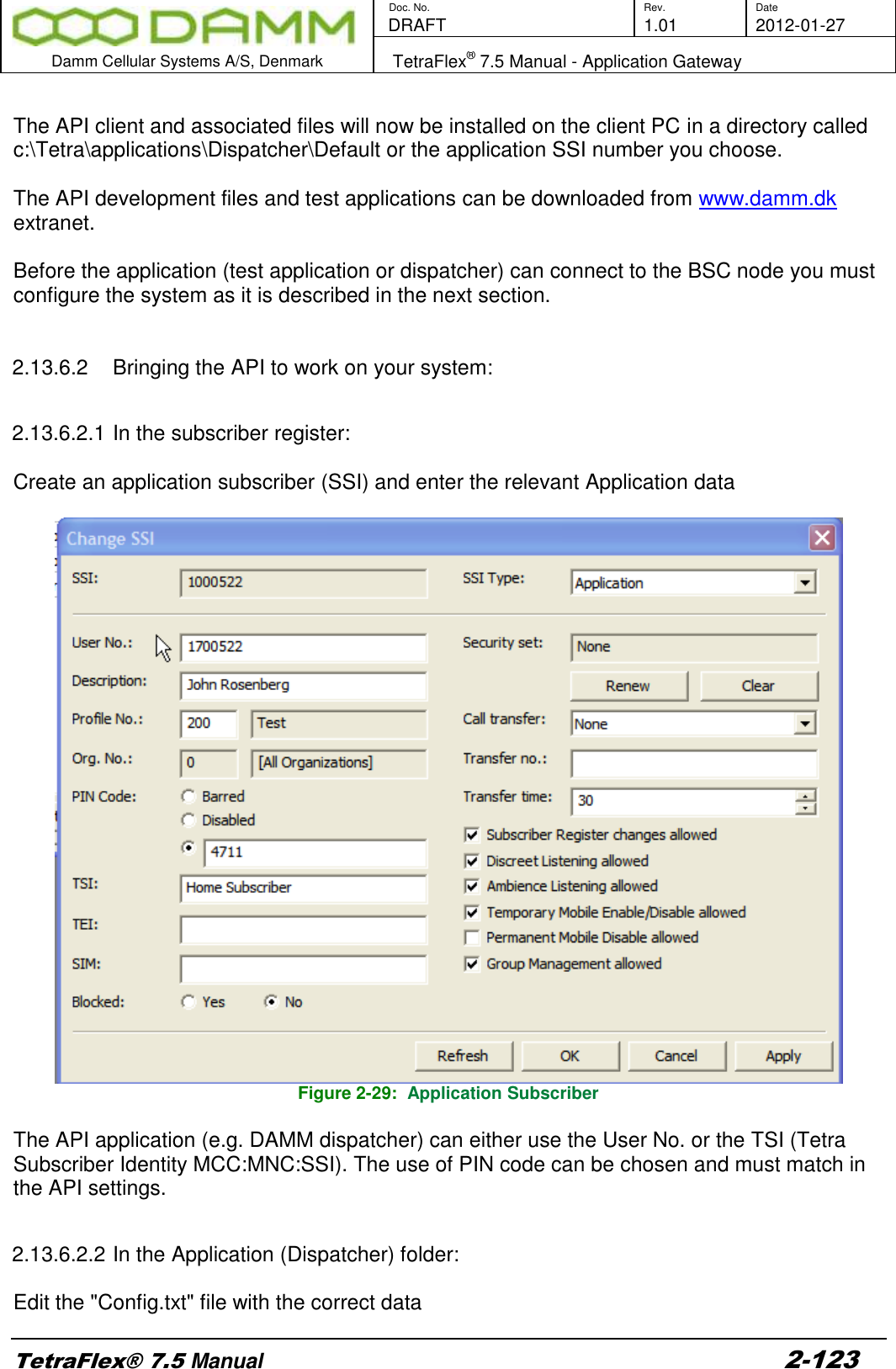
![Doc. No. Rev. Date DRAFT 1.01 2012-01-27 Damm Cellular Systems A/S, Denmark TetraFlex® 7.5 Manual - Log Server TetraFlex® 7.5 Manual 2-99 Please see the following LogServer.ini file description that corresponds to the fields in the LogServer Configuration tab except fields marked with * . LogServer.ini Section [LogServer] Name Type Default Value Description DBServer* String localhost This is either the machine name or IP address of the SQL Server. DBInitialCatalog* String TetraFlexLogDB This is the name of the database which should be connected to. DBLoginName* String root This is the login name to the database. DBLoginPwd* String tetra This is the password to the database. LogServerDescr String Default LogSrv Description This is a textual description of a maximum of 32 characters describing this instance of the LogServer. This info is sent to NM, and is visible there along](https://usermanual.wiki/Damm-Cellular-Systems-A-S/104012.User-manual-2/User-Guide-1739424-Page-29.png)
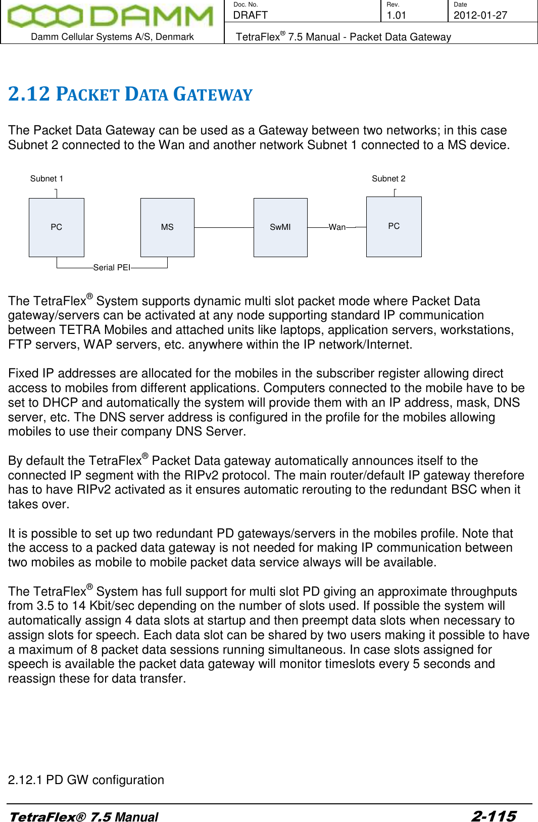
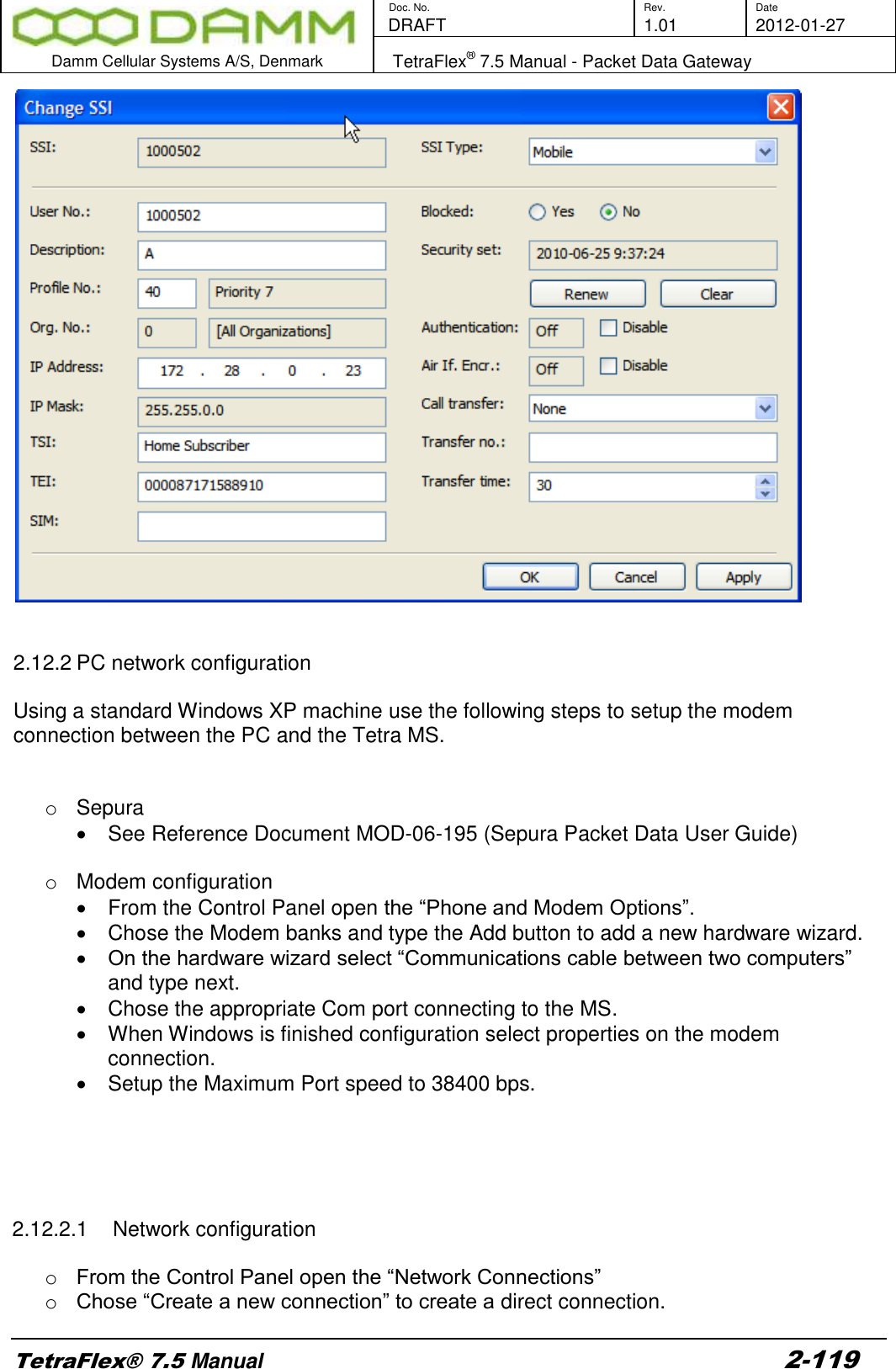
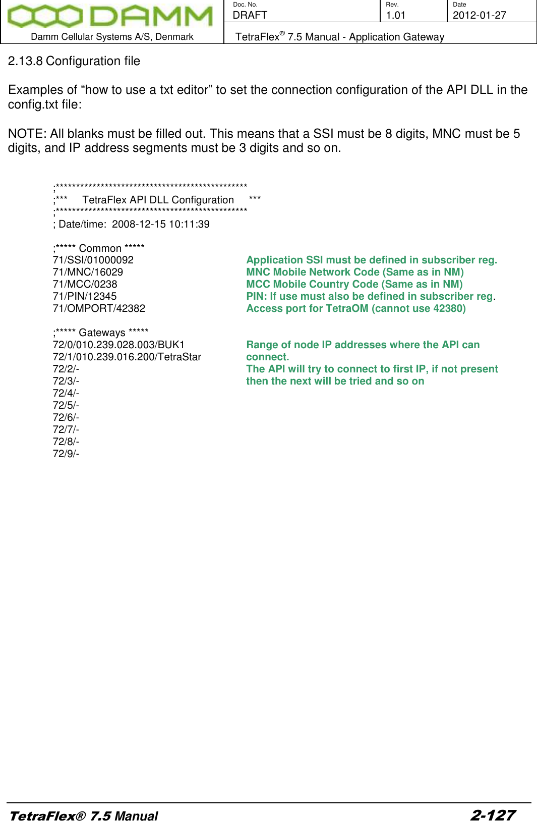
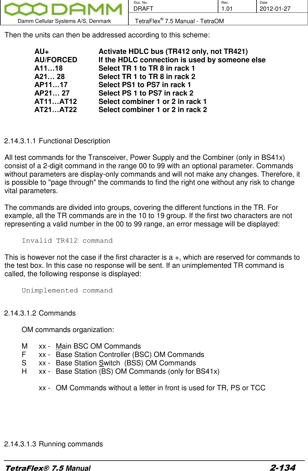
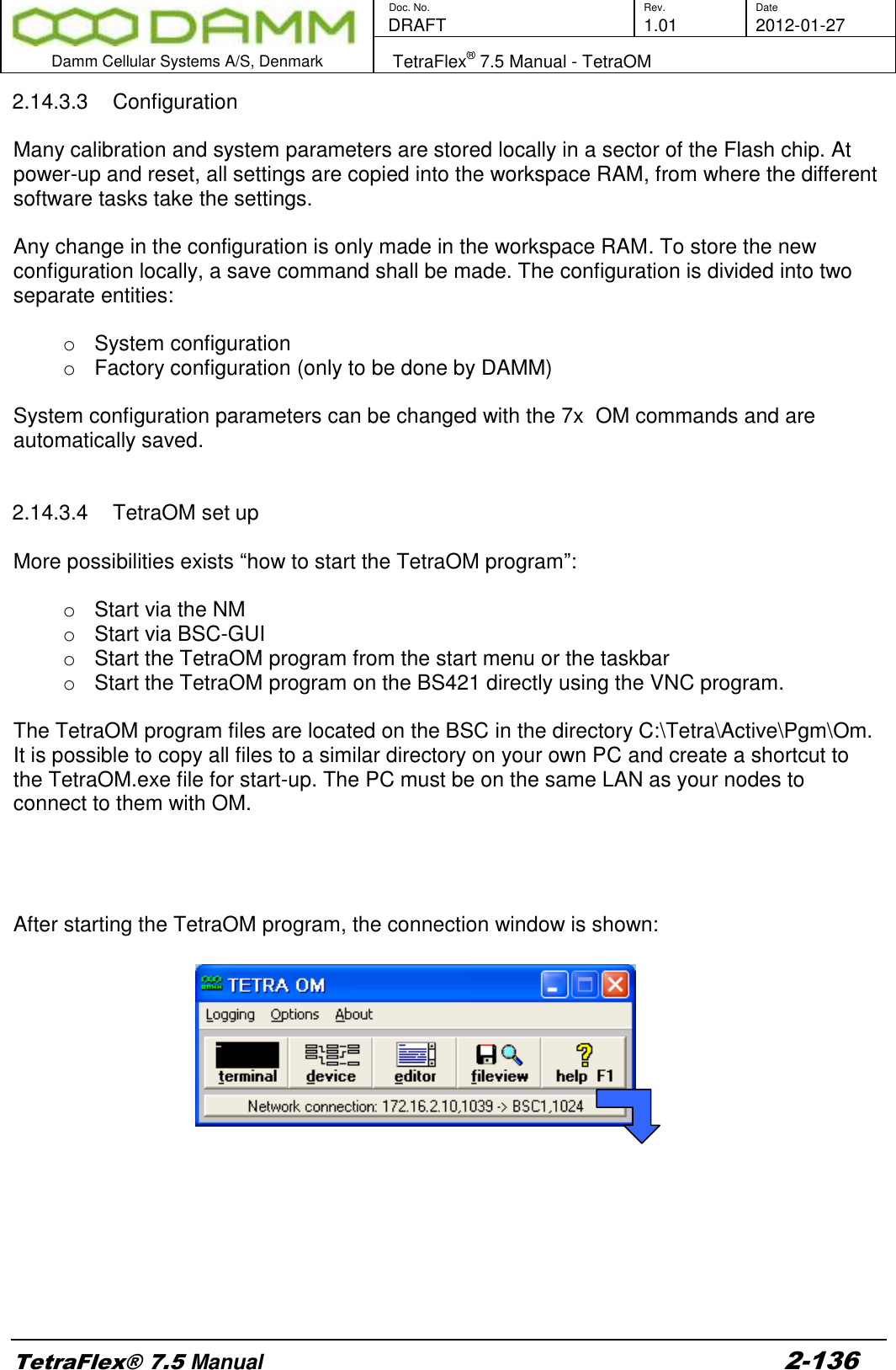
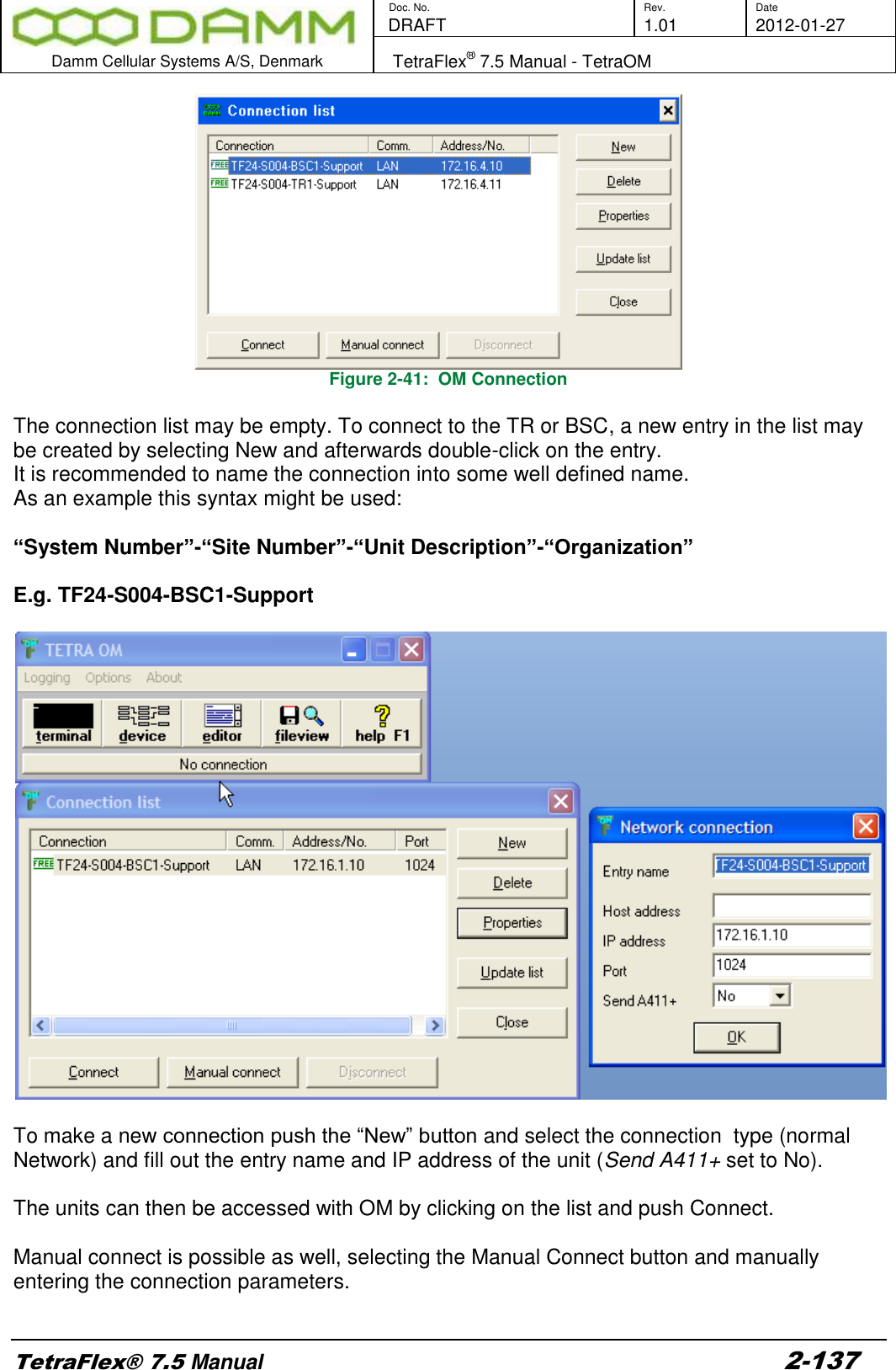
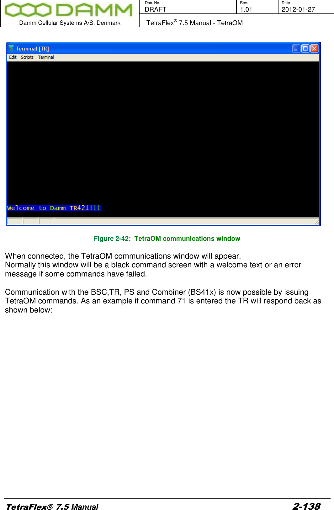
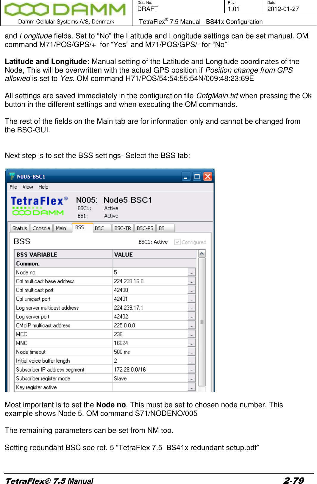
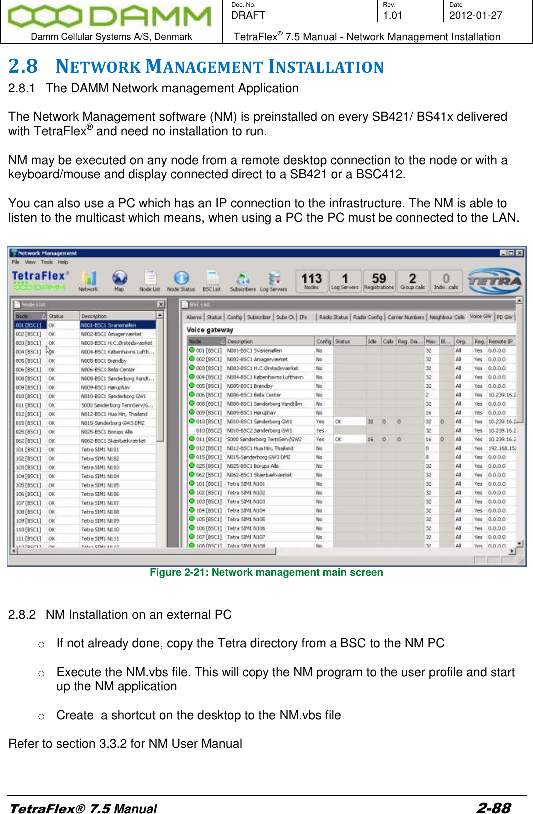
![Doc. No. Rev. Date DRAFT 1.01 2012-01-27 Damm Cellular Systems A/S, Denmark TetraFlex® 7.5 Manual - TetraOM TetraFlex® 7.5 Manual 2-133 For the indoor BS41x, IP connection to the TR412’s, combiner and Power supply is not possible and must be made via the HDLC bus. To activate the HDLC bus UART, use TetraOM command AU+. If for some reasons the HDLC cannot be activated use AU/FORCED first. For onsite situations, a CRT, keyboard, and mouse can be connected directly to the BSC with standard extension cables. This also allows monitoring of the Windows booting, modification of the BIOS CMOS set-up, and makes it possible to alter the IP address when lost. When a TCP/IP connection is available, file transfer to and from the BSC is possible and may be used for backup, restore and software upgrade. 2.14.2 Power supply addressing outdoor (SB421) The internal Power supply in the SB421 can be addressed with the OM command: AP When succeed, the response from the PS is Address: AP [PS421] Note: The Power Supply can only be addressed when the SB421 IP address is selected in the connection list. 2.14.3 TR421, Combiner, Power supply addressing indoor (BS4xx) To get access to these units the IP address for the BSC must be used and Port 42024 as shown in the connection list below:](https://usermanual.wiki/Damm-Cellular-Systems-A-S/104012.User-manual-2/User-Guide-1739424-Page-63.png)