Damm Cellular Systems A S 104012 410 MHZ TRANSCEIVER MODULE User Manual TetraFlex 7 5 Manual
Damm Cellular Systems A/S 410 MHZ TRANSCEIVER MODULE TetraFlex 7 5 Manual
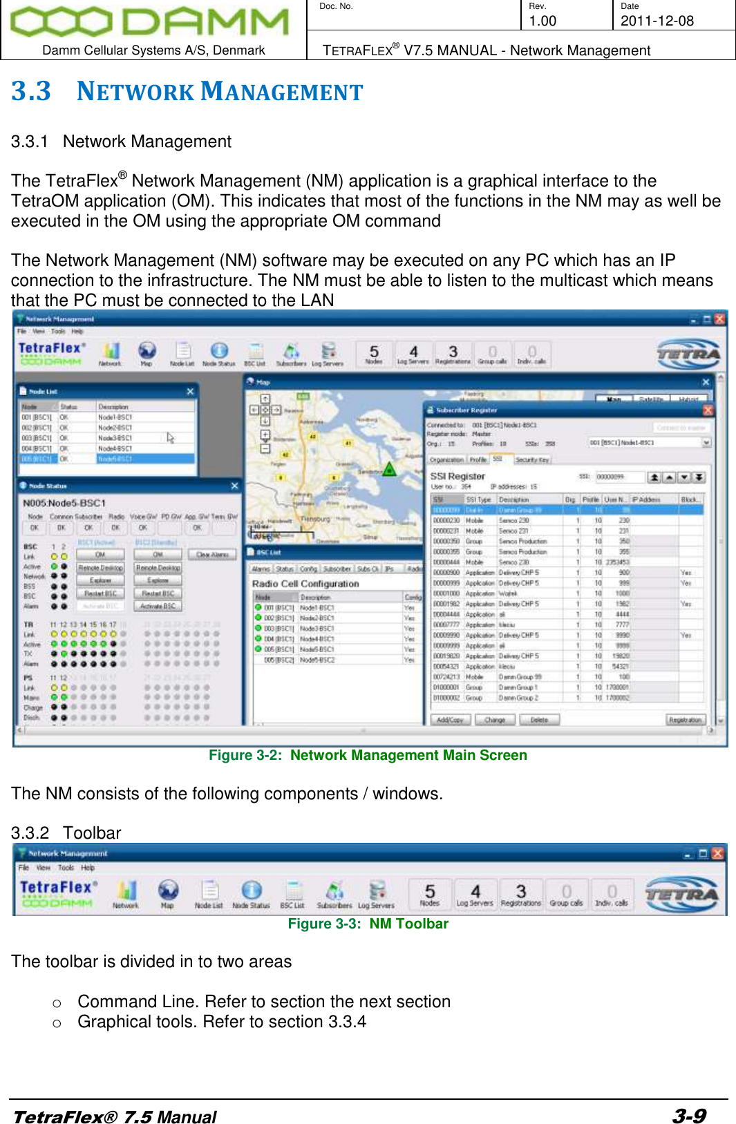
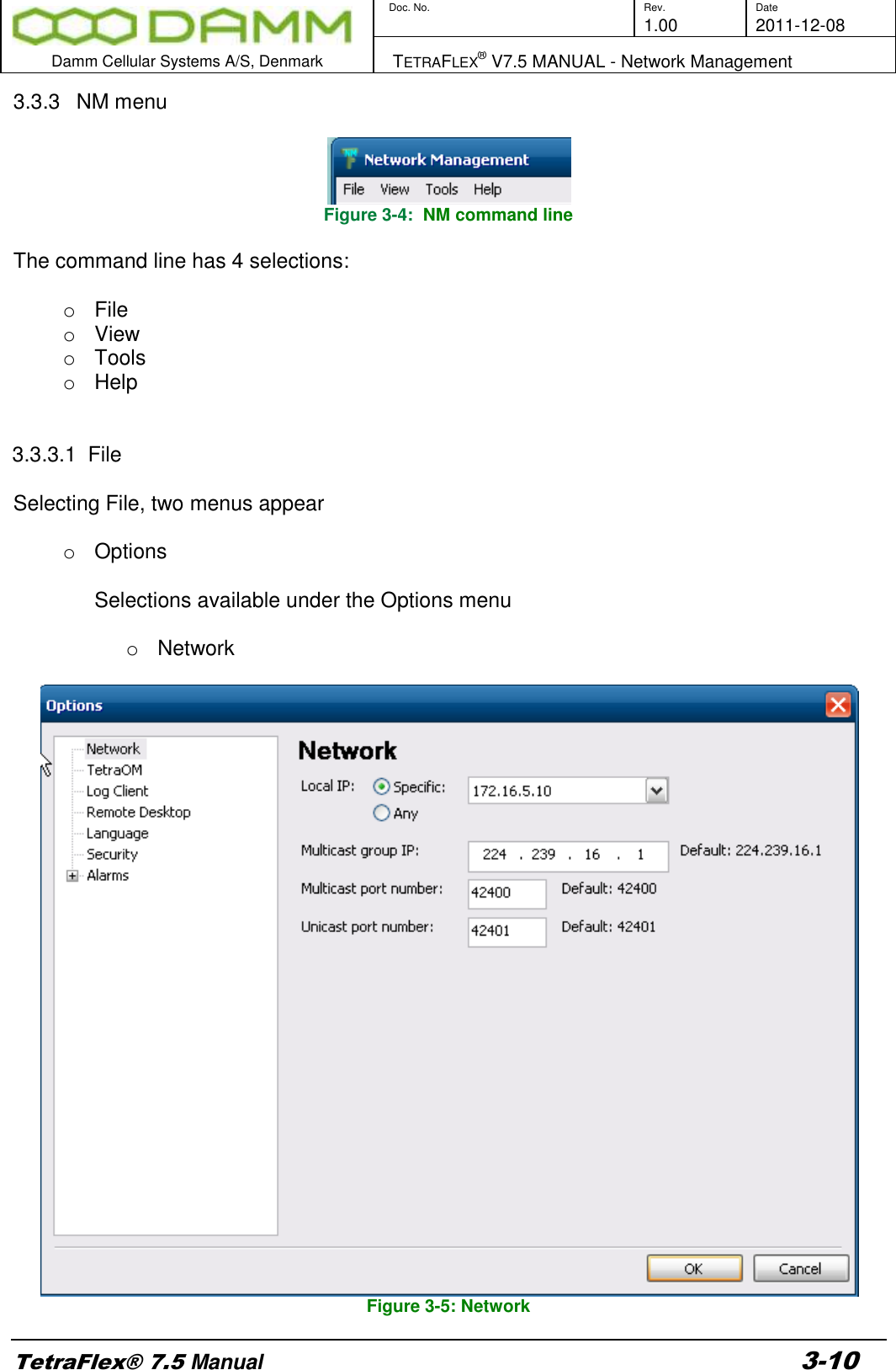
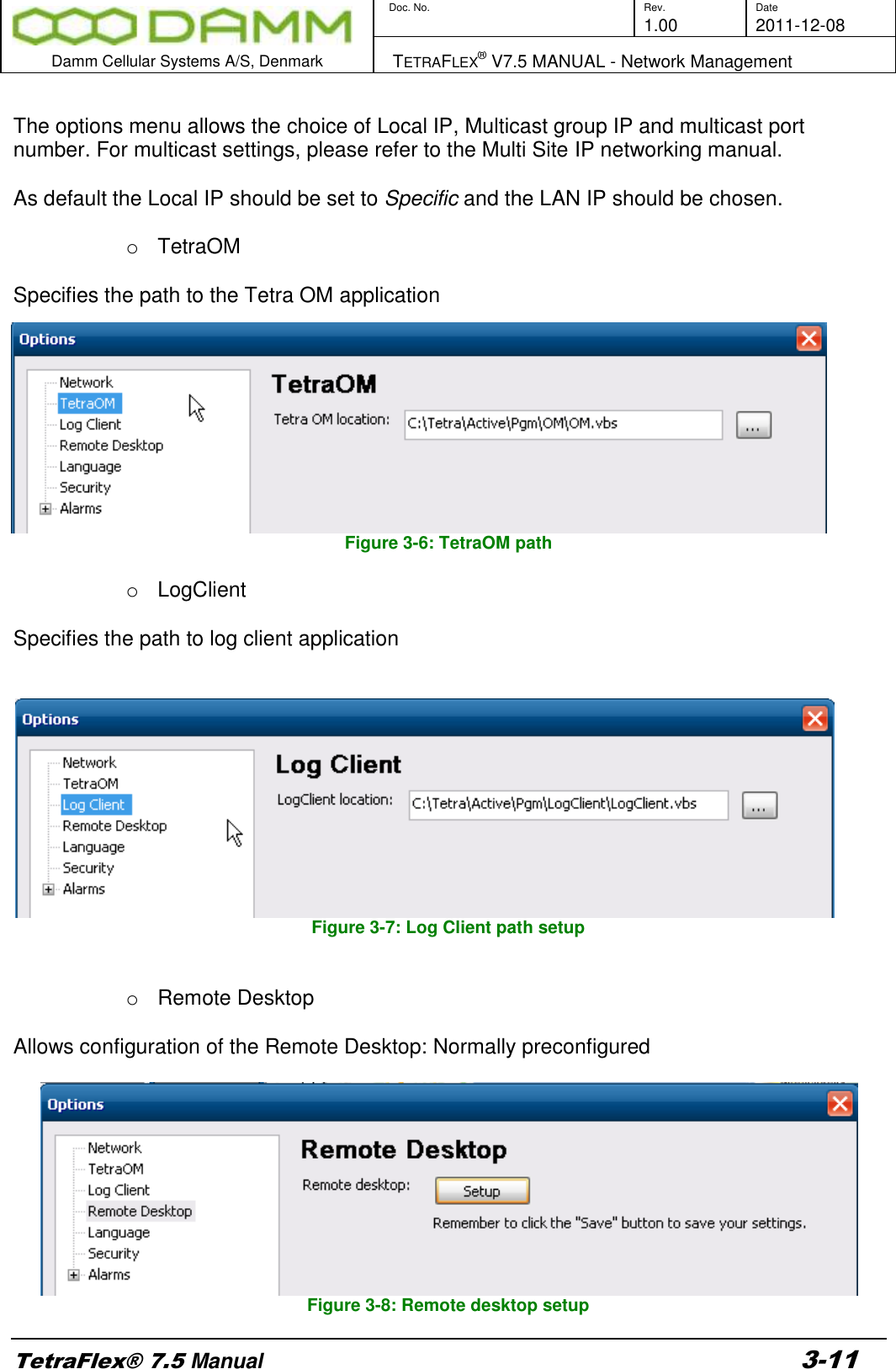
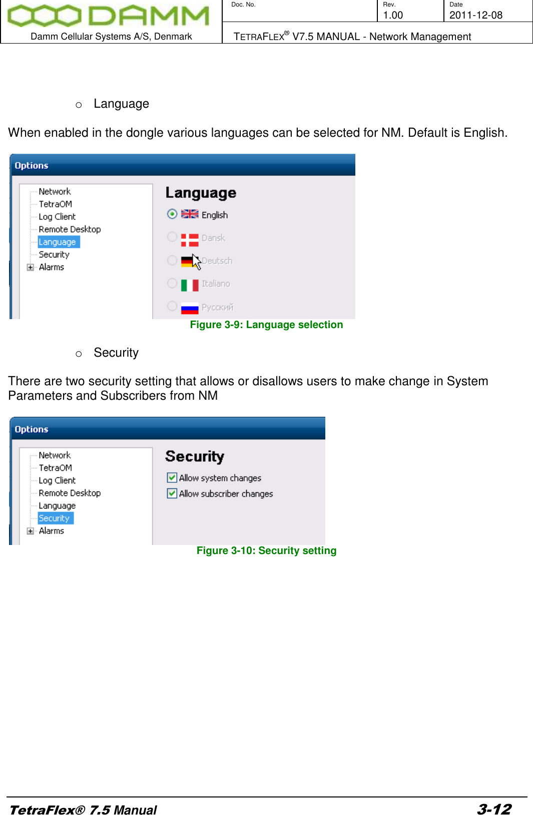
Contents
- 1. User Manual - 1
- 2. User manual - 2
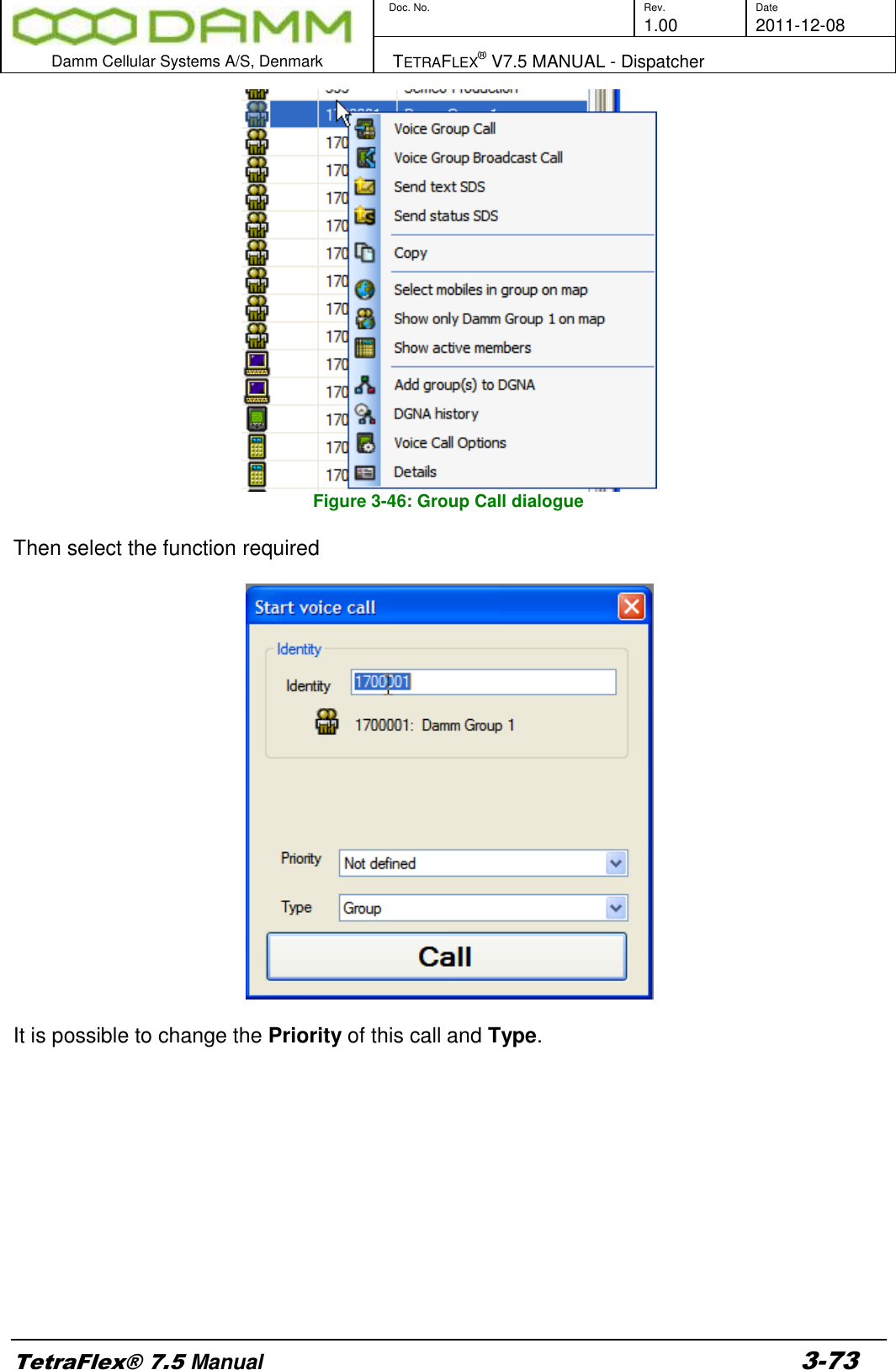
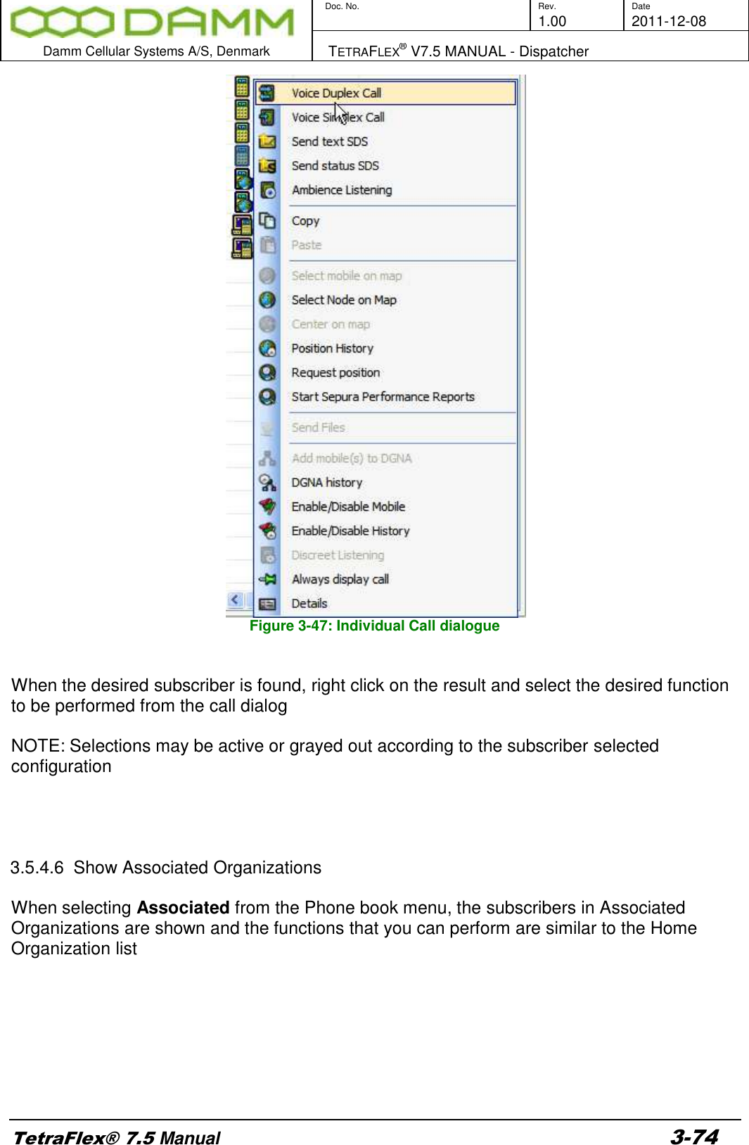
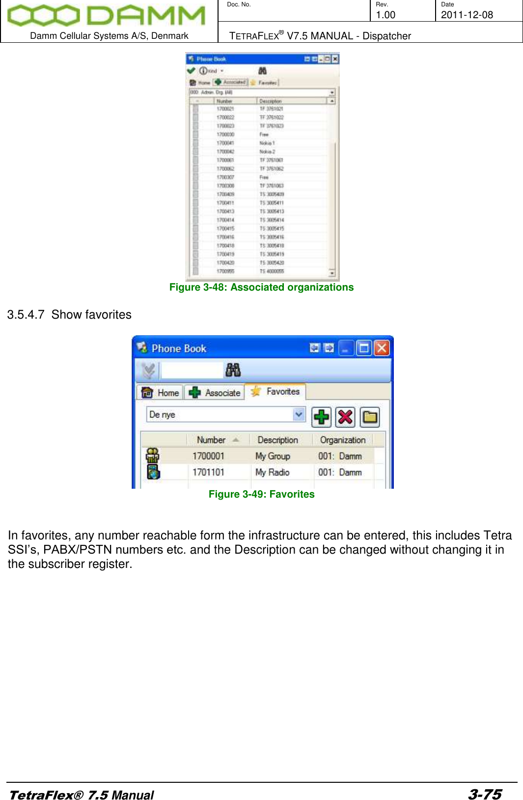
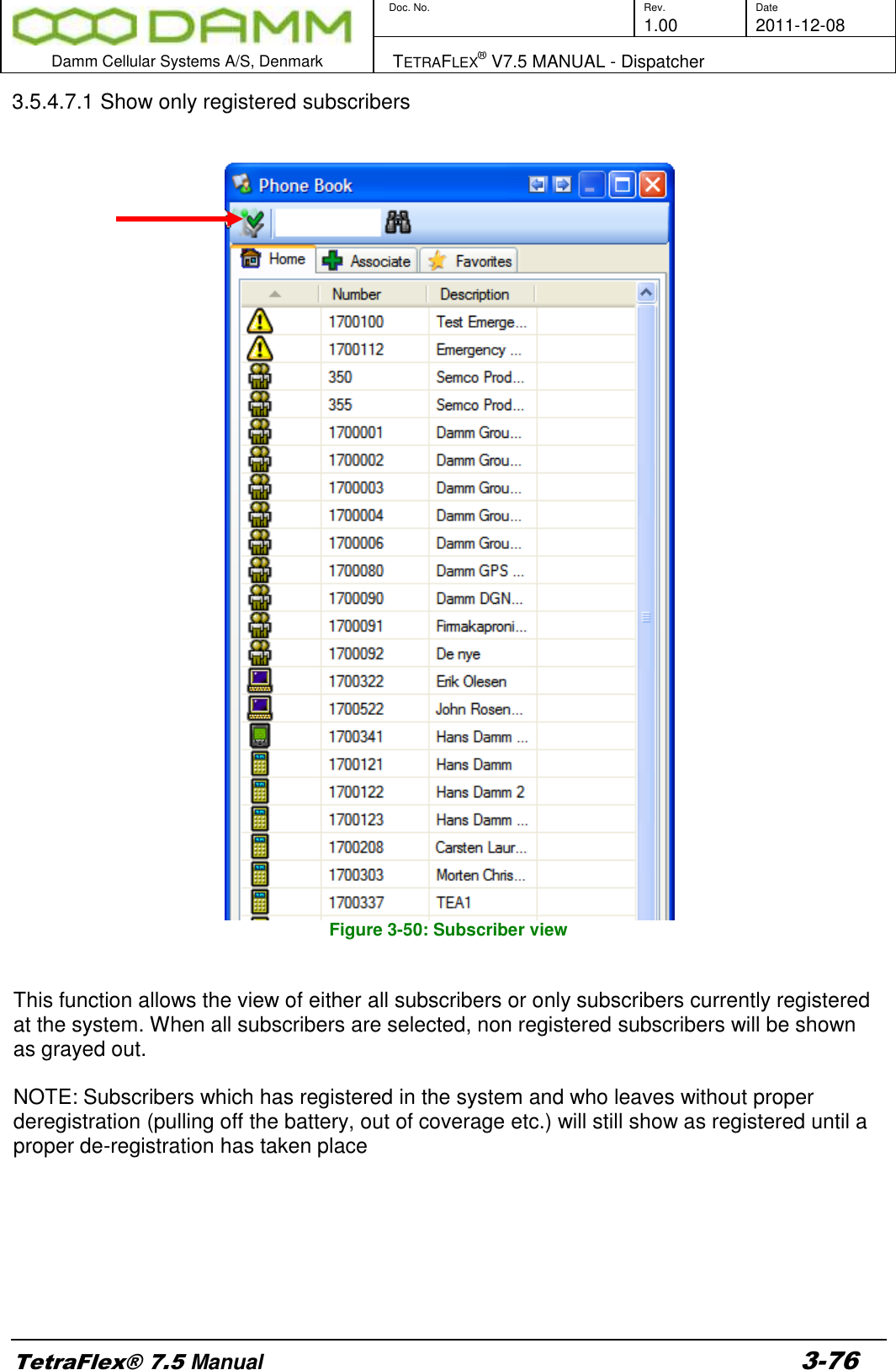
- 3. User Manual - 3
- 4. User Manual - 4
- 5. Warning statements for user's manual
- 6. Notes to installer for user manual
- 7. Revised pages 4 and 5 of the user's manual 11 01 2012
- 8. User addendum 4 carrier 11 01 12
- 9. User addendum 8 carrier 11 01 2012
- 10. Note to installers to be placed in user manual
User Manual - 3