DareGlobal Technologies DSL-500 ADSL MODEM User Manual
Shanghai DareGlobal Technologies Co., Ltd. ADSL MODEM
Users Manual
ADSL MODEM
USER MANUAL

ADSL MODEM USER MANUAL
- 2 -
CONTENTS
1. OVERVIEW..................................................................................................................................4
1.1 ABOUT ADSL................................................................................................................4
1.2 DEVICE INTRODUCTION..........................................................................................4
1.3 PROTOCOLS ...............................................................................................................5
1.4 FEATURES .....................................................................................................................5
2. HARDWARE INSTALLATION AND SOFTWARE CONFIGURATION..............................6
2.1 SYSTEM REQUIREMENT .........................................................................................6
2.2 HARDWARE INSTALLATION ....................................................................................6
2.2.1 HARDWARE CONNECTION..................................................................................6
2.2.2 INSTALLATION STEPS...........................................................................................6
2.3 SOFTWARE CONFIGURATION................................................................................7
2.3.1 PREPARATION BEFORE SOFTWARE INSTALLATION .....................................7
2.3.2 COMPUTER CONFIGURATION ............................................................................7
2.3.3 ADSL MODEM CONFIGURATION........................................................................7
2.3.4 ADSL MODEM WORK MODE CONFIGURATION..............................................8
2.3.5 ADSL MODEM SOFTWARE INTRODUCTION....................................................8
3. PROTOCOL CONFIGURATION............................................................................................10
3.1 HIERARCHY OF PROTOCOLS ..............................................................................10
3.2 RFC1483 BRIDGE CONFIGURATION...................................................................10
3.3 STATIC ROUTING CONFIGURATION...................................................................13
3.4 PPPOA AND PPPOE CONFIGURATION ..............................................................16
4. APPLICATION OF DHCP .......................................................................................................18
4.1 TCP/IP PROTOCOL CONFIGURATION................................................................18
4.2 MODEM CONFIGURATION.....................................................................................18
5. OTHER FUNCTIONS AND CONFIGURATION...................................................................21
5.1 STATUS CHECKING.................................................................................................21
5.2 CONFIGURATION OF MODEM’S IP ADDRESS AND PASSWORD................22
6. RESET TO DEFAULT SETTING............................................................................................23
7. SPECIFICATION.......................................................................................................................24
7.1 POWER SUPPLY.......................................................................................................24
7.2 STANDARDS..............................................................................................................24
7.3 ENVIRONMENT REQUIREMENTS........................................................................24
APPENDIX .....................................................................................................................................25
APPENDIX A. TROUBLESHOOTING...........................................................................25
APPENDIX B. SPLITTER CONNECTION....................................................................26
APPENDIX C. CONFIGURATION OF TCP/IP PROTOCOL.................................................27
APPENDIX D. SHIPPING LIST......................................................................................29

ADSL MODEM USER MANUAL
- 3 -
Reference Standards
Related Documents
Definition & Acronyms
ATU-C ADSL Transceiver Unit, Central Office End
ATU-R ADSL Transceiver Unit, Remote Terminal End
FEXT Far-end Cross Talk
HDSL High-rate Digital Subscriber Line
POTS Plain Old Telephone Service
PSTN Public Switched Telephone Network
WINS Windows® Internet Name Server
ADSL Asymmetric Digital Subscriber Line
OAM Operations, Administration And Maintenance
QAM Quadrature Amplitude Modulation
DMT Discrete Multitone
DSL Digital Subscriber Line
FEC Forward Error Correction
ATM Asynchronous Transfer Mode
WAN Wide Area Network
PRD Pseudo-random Downstream
PRU Pseudo-random Upstream
USB Universal Serial Bus
LAN Local Area Network
PVC Permanent Virtual Circuit
SVC Switched Virtual Circuit
PPP Point to Point protocol
DNS Domain Name Server
VPI Virtual Path ID
VCI Virtual Circuit ID
DSL Digital Subscriber Line
IP Internet Protocol
CO Central Office
EC Echo Canceling
ADSL MODEM USER MANUAL
- 4 -
1. OVERVIEW
1.1 ABOUT ADSL
ADSL MODEM is a broadband Internet access device,which utilizes the high frequency segment of the
phone line to transmit high-speed data without interfering with the voice transmission. The frequency of ADSL
signal is higher than that of voice, so voice and ADSL signal can coexist in one line by using a splitter to
insulate each from the other. ADSL data transfer on the asymmetry way. The upload speed is up to 1Mbps and
download speed is up to 8Mbps. It is an ideal device for broadband access.
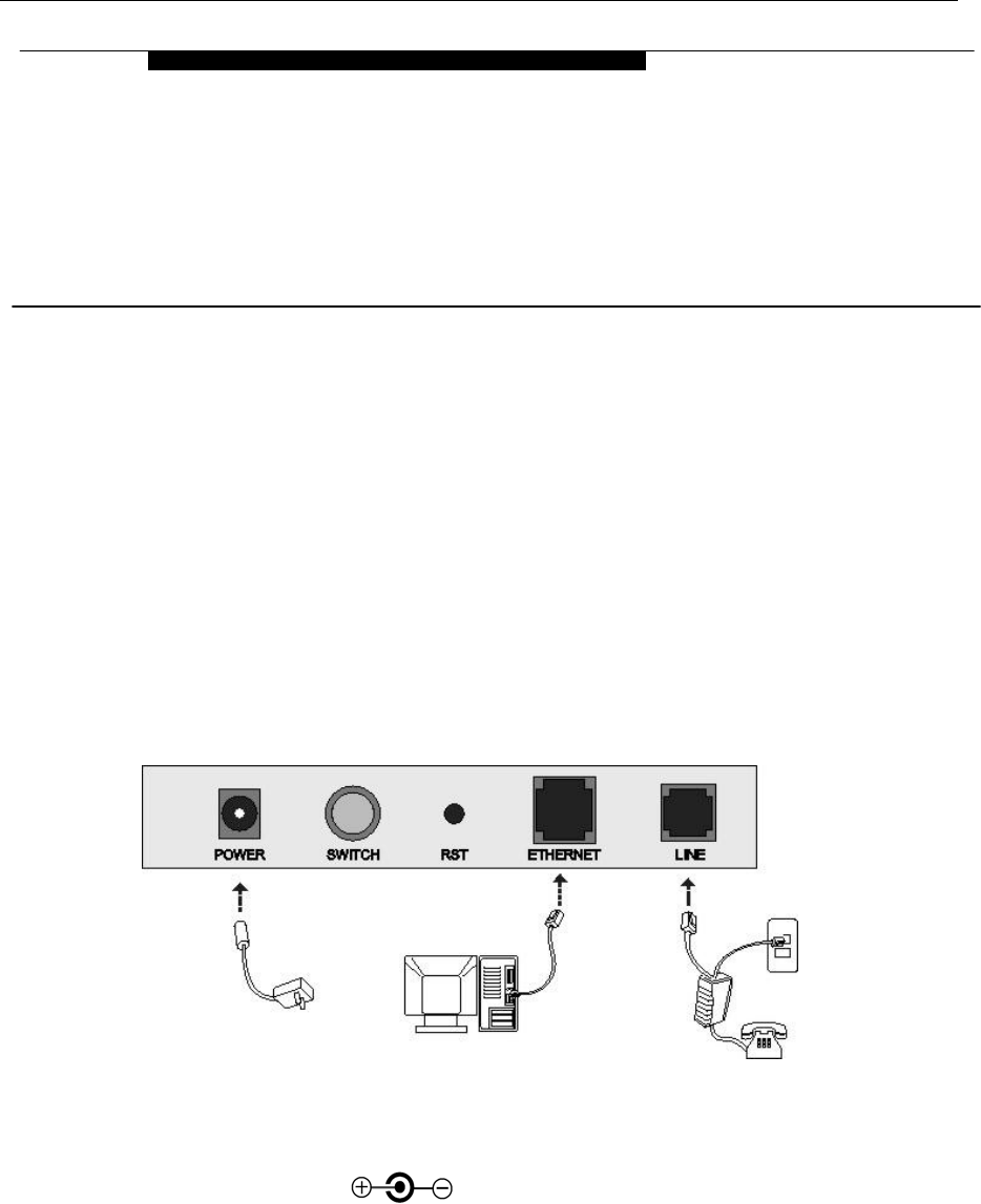
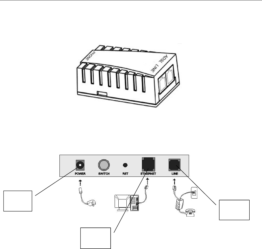
1.2 DEVICE INTRODUCTION
Figure 1.1
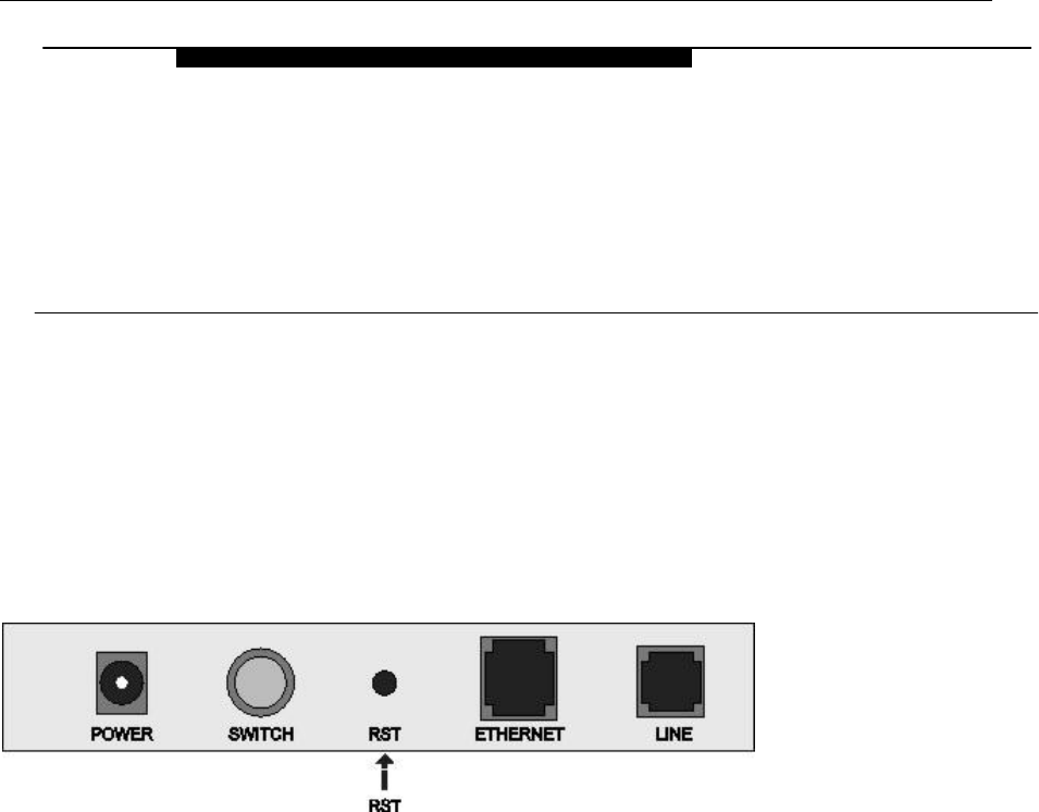
Interface introduction:
① Power Interface: 5.2V DC, 1000mA.
② Power switch: To turn on or off the power.
③ Reset Key: Reset default configuration.
④ Ethernet Interface: To be connected to a PC or a HUB by a CAT 5 twisted parallel cable. A straight-through
network cable should be used when it is connected to a PC network card and a
crossover cable should be used for UP LINK interface of HUB.
⑤ Line Interface: To be connected to a telephone.
1
OVERVIEW

ADSL MODEM USER MANUAL
- 5 -
1.3 LED STATUS INDICATION
Table 1.1
Status POWER
(red)
LINK (yellow) DATA (green) PC(green)
Steady
light
Power on The modem is
in good
connection
/ Ethernet line is connected
Flashing / No signal / /
Fast
flashing
/ In handshaking
status
Transmitting or receiving data /
Off Power off Power off Not connected with PC
properly
Ethernet line not connected
properly
1.4 PROTOCOLS
ADSL Modem supports the following protocols:
1. PPPoA(PPP over ATM ) LLC encapsulation or VCMUX encapsulation (RFC2364)
2. PPPoE (PPP over Ethernet) LLC encapsulation or VCMUX encapsulation (RFC2516)
3. 1483 bridge(1483 Bridged IP over ATM)LLC encapsulation or VCMUX encapsulation (RFC1483)
4. 1483 routing(1483 Routing IP over ATM)LLC encapsulation or VCMUX encapsulation(RFC1483)
5. Classical IP over ATM (RFC1577)
1.5 FEATURES
1. Supports ANSI T1.413 ISSUE 2, ITU G.992.1 (G.DMT) and ITU G.992.2 (G.LITE),ADSL2/2+.
2. Web-based configuration and monitoring.
3. Supports up to 8 PVCs.
4. Routing function.
5. NAPT、DHCP function.
6. Maximum upstream transmission rates of 1Mbps
7. Maximum downstream transmission rates of 8 Mbps
8. Software upgradeable.
9. Transmission distance up to 5 km.
10. ATM management function.
11. Based on EOA long distance management
ADSL MODEM USER MANUAL
- 6 -
2. HARDWARE INSTALLATION AND SOFTWARE
CONFIGURATION
2.1 SYSTEM REQUIREMENT
A computer with a network card with Ethernet interface.
2.2 HARDWARE INSTALLATION
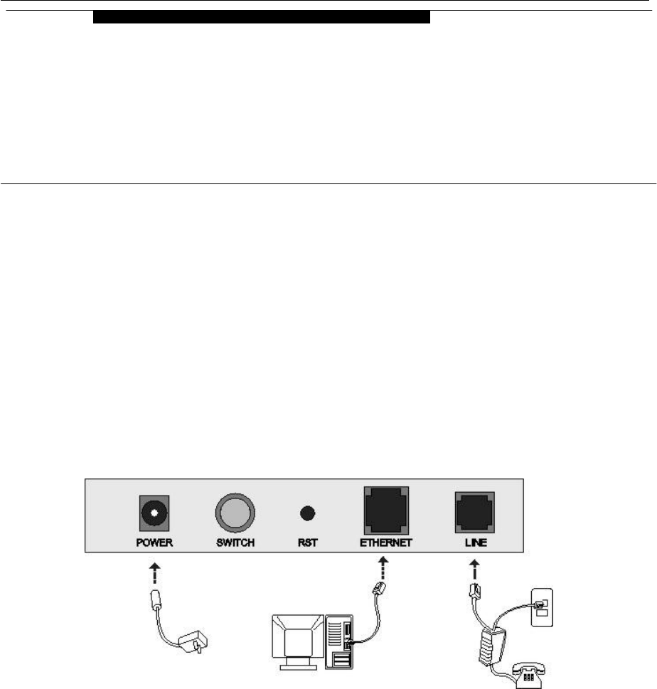
2.2.1 HARDWARE CONNECTION
Figure 2.1
To go online and make phone calls simultaneously, please refer to Appendix B: SPLITTER
CONNECTION.
2.2.2 INSTALLATION STEPS
1. Connect line port⑤ of the ADSL MODEM to telephone jack with the telephone cord that comes with the
modem.
2. Connect Ethernet port④ of the ADSL MODEM to Ethernet port of the computer using the network cable
that comes with the modem.
3. Plug in the power cord ①, and turn on the power.
2
HARDWARE INSTALLATION AND
SOFTWARE CONFIGURATION
ADSL MODEM USER MANUAL
- 7 -
2.3 SOFTWARE CONFIGURATION
2.3.1 PREPARATION BEFORE SOFTWARE INSTALLATION
Before the installation, please confirm information below or consult with the ADSL service provider. Table
2.1 shows all the information needed to configure for different protocols.
Table 2.1
Virtual Dial Mode Private Line Mode
Protocol PPPOE PPPOA 1483 Bridged 1483 Routed 1577 Private Line
VPI VPI VPI VPI VPI
VCI VCI VCI VCI VCI
User name User name IP address/Sub
mask IP address/Sub
mask
Necessary
Information
Password Password Gateway Gateway
2.3.2 COMPUTER CONFIGURATION
The default factory-set IP Address for the ADSL MODEM is: 192.168.1.1. The Subnet Mask is:
255.255.255.0. Users can configure ADSL MODEM through an Internet browser. ADSL MODEM can be used
as a gateway and DNS server and users need to set the computer’s TCP/IP protocol as follow:
1. Set the computer at same Internet segment with ADSL MODEM so as to enter ADSL MODEM
configuration page through a browser.
2. Set the computer’s gateway’s IP address the same as the ADSL Modem’s.
3. Set the computer’s DNS server’s IP address the same as the ADSL Modem’s or that of an effective DNS
server.
If the user has any question regarding the computer’s TCP/IP protocol, please refer to APPENDIX C:
TCP/IP PROTOCOL CONFIGURATION.
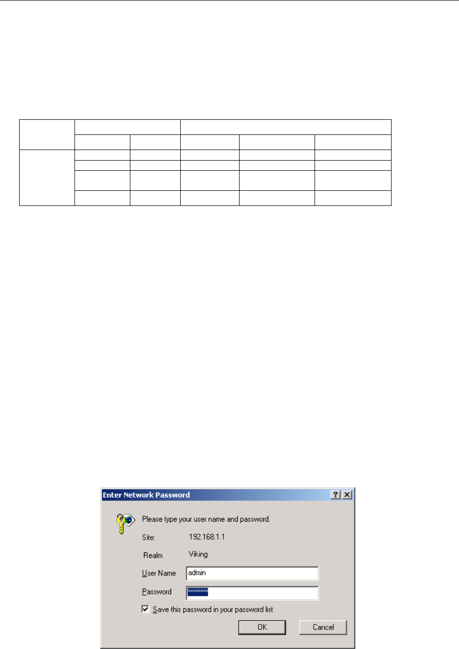
2.3.3 ADSL MODEM CONFIGURATION
Open the browser; input http://192.168.1.1 in the address column. Press “Enter” key then the entry dialog
box will pop up as Figure 2.2, Input username: admin, and password: password (Note that this is capital
sensitive), then press “Enter”. The ADSL MODEM configuration page will be shown.
Figure 2.2
ADSL MODEM USER MANUAL
- 8 -
2.3.4 ADSL MODEM WORK MODE CONFIGURATION
1. For different protocols, the users need to set ADSL Modem accordingly as listed below:
Table 2.2
ATM VC Protocol Use DNS User Name Password
√ PPPoE Enable √ √
PPPoE
PPPoA √ PPPoA Enable √ √
Lower interface Default route
1483 Bridged √ Disable
Lower interface IP Address Sub mask Gateway Address
1483 Routed
√ √ √ √
Lower interface IP Address Sub mask IPoA Mode Gateway Address 1577
Private Line √ √ √ 1577 √
Note: √ means configure according to ADSL service provider’s instructed value.
PPPoE can also be realized via third party dialup software.
PPPoE PPPoA 1483 Bridged 1483 Routed 1577 Private Line
User Manual
Reference Chapter 3.4 3.4 3.2 3.3 3.3
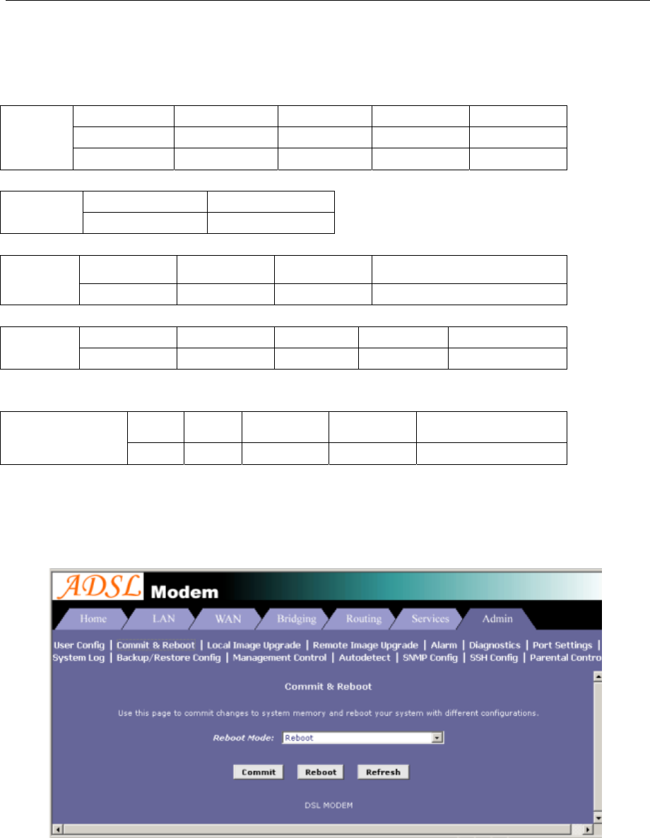
2. After getting through every page for parameters set-up, click “Submit” to save the value in ADSL
MODEM
3. Click the “Commit & reboot” on “Admin” Tab to enter the saving configuration page as Figure 2.3. Click
“Commit”button to save the setting. Click “Reboot” button to reboot the ADSL MODEM. The ADSL
MODEM will work on the new parameters.
Figure 2.3
2.3.5 ADSL MODEM SOFTWARE INTRODUCTION
The same toolbar will appear on different pages, for example“LAN config”is on the page“LAN”and
“Routing”. You can modify on either page.

ADSL MODEM USER MANUAL
- 9 -
1. Home
The page shows the complete configuration. You can click any item to enter the detail configuration page.
2. LAN
You can set the IP address and subnet mask, configure the modem as DHCP server, or add DHCP pool on
the page.
3. WAN
You can check the ADSL’s working status and parameters, add/edit or delete ATM lower interface, add/edit
or delete PPP、EOA and IPOA protocol.
4. Bridging
You can add/delete bridging interface on the page. You can also open and close the bridged mode, set LAN,
check DSL parameters, add/delete ATM interface and EOA interface.
5. Routing
You can find the routing table on this page. Other functions could be done on other pages previously
described.
6. Services
You can configure the NAT, RIP, firewall and DNS or check it on this page.
7. Admin
You can modify user’s password, save modified configuration, reboot ADSL MODEM, update software,
and check alarm and port settings information and diagnostics on this page
Usually you will be able to complete most of the settings needed on the pages of Home, LAN, WAN,
Admin.
ADSL MODEM USER MANUAL
- 10 -
3. PROTOCOL CONFIGURATION
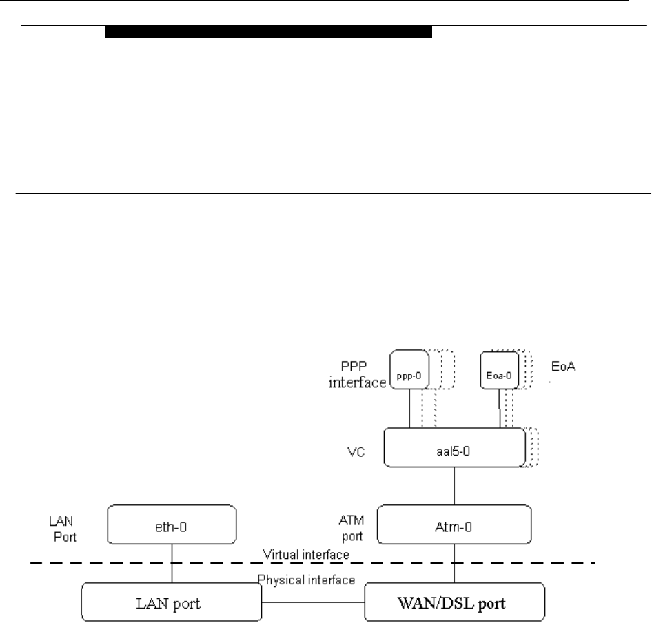
3.1 HIERARCHY OF PROTOCOLS
The hierarchy of protocols interface is shown in Figure 3.1.
Figure 3.1
Both PPP and EOA module are build on ATM level interface. If you want to setup PPP, EOA or IPOA modules
you must ensure you have an ATM interface first. Please configure protocol modules as stated below:
1. Setup LAN module Eth-0;
2. Setup ATM module. The user can click the “Add”, “Edit” or “Delete” button of ATM VC toolbar in the
page “WAN” to create, edit or delete ATM modules;
3. Setup PPP, EOA or IPOA modules, the user can click the “Add”, “Edit” or “Delete” button of PPP,
EOA or IPOA toolbars in the page of WAN to create, edit or delete different protocol modules.
3.2 RFC1483 BRIDGE CONFIGURATION
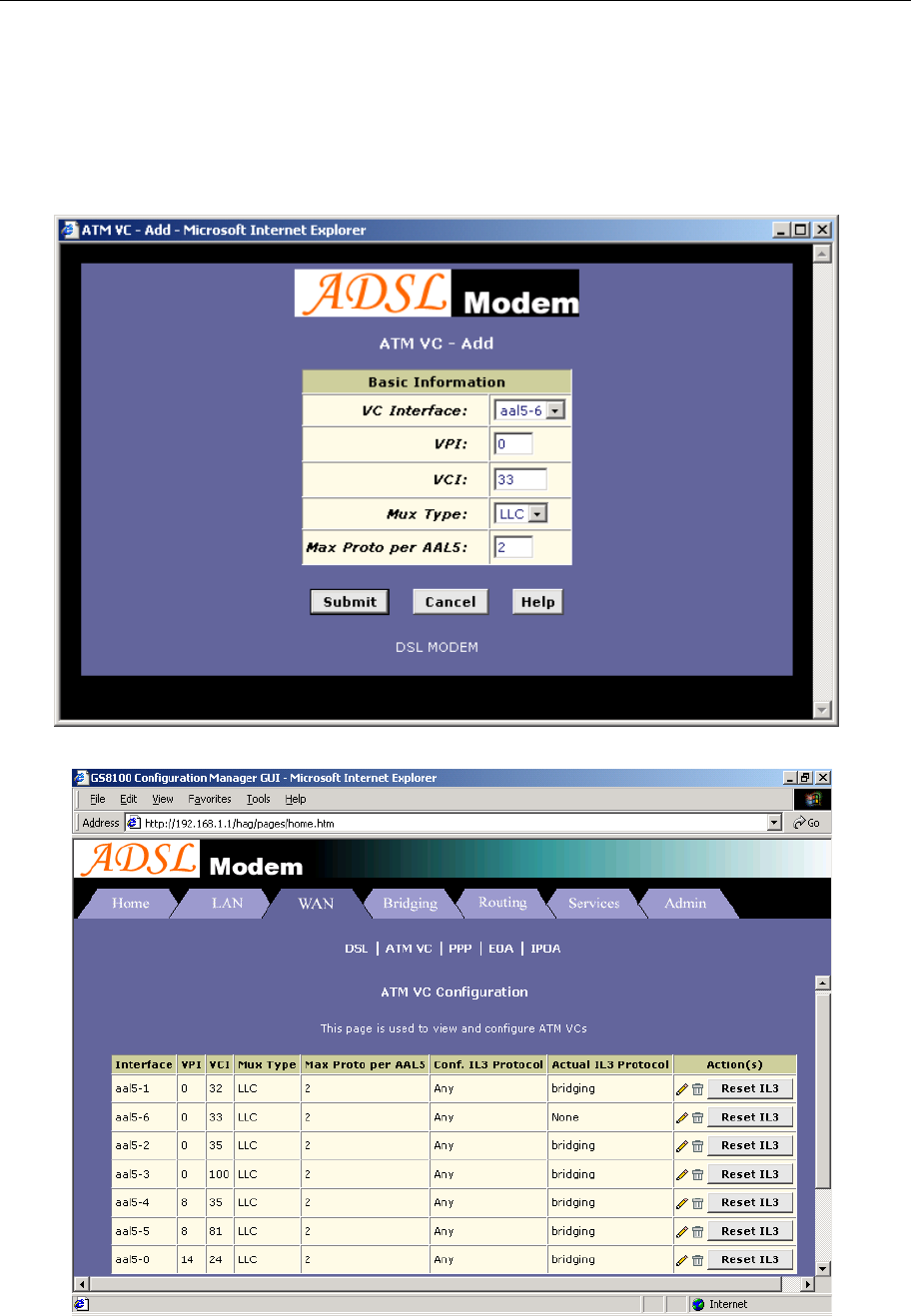
1. ATM VC Configuration
− The user can edit, create and delete ATM VC level module. The factory-set configuration has 6 ATM
VCs.
3
PROTOCAL CONFIGURATION
ADSL MODEM USER MANUAL
- 11 -
− Then we will add one more ATM PVC module: aal5-6 (VPI=0, VCI=33) as an example, and use this
PVC to setup a RFC1483 Bridge.
− Click the ATM VC label in Page “WAN”, then click “Add” button in the ATM VC toolbar, the pop up
Window is shown as Figure 3.2.
− Type number “0” in VPI item and “33” in the VCI item, then click “Submit” button. The result window
is shown as Figure 3.3.
Figure 3.2
Figure 3.3
ADSL MODEM USER MANUAL
- 12 -
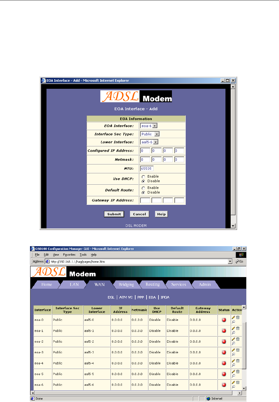
2. EOA Configuration
Click EOA label. The factory –set configuration has 6 EOAs. Here we add one EOA : eoa-6 as an
example.
− Click “Add” button, the pop up Window is shown as Figure 3.4.
− Choose aal5-6 option for Lower interface; Disable option for Default Route. Don’t change other
items.
− Click “Submit” button, the result window is shown as Figure 3.5.
Figure 3.4
Figure 3.5
ADSL MODEM USER MANUAL
- 13 -
3. Click “Bridging” Page -> choose eoa-6 option for interface name -> click “Add” button -> click “Submit”
button.
4. Click “Commit & Reboot” label in the page Admin, shown as in Figure 2.3. Click “Commit” button to
save. When it shows “Changes Committed Successfully...” click “Reboot” button or turn off then turn on
the ADSL MODEM. The MODEM will work on the new parameters.
3.3 STATIC ROUTING CONFIGURATION
(RFC1483 routing/RFC1577configuration)
1. RFC1483 routing
a) ATM VC configuration
Use one of the ATM VCs which we had added in 3.2 for example: aal5-6 (VPI=0, VCI=33)
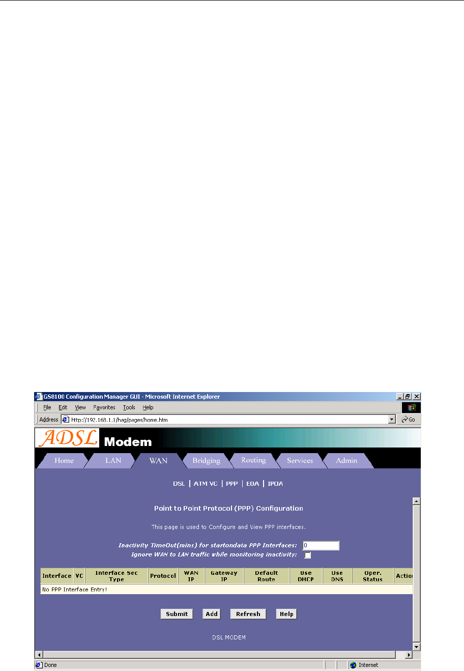
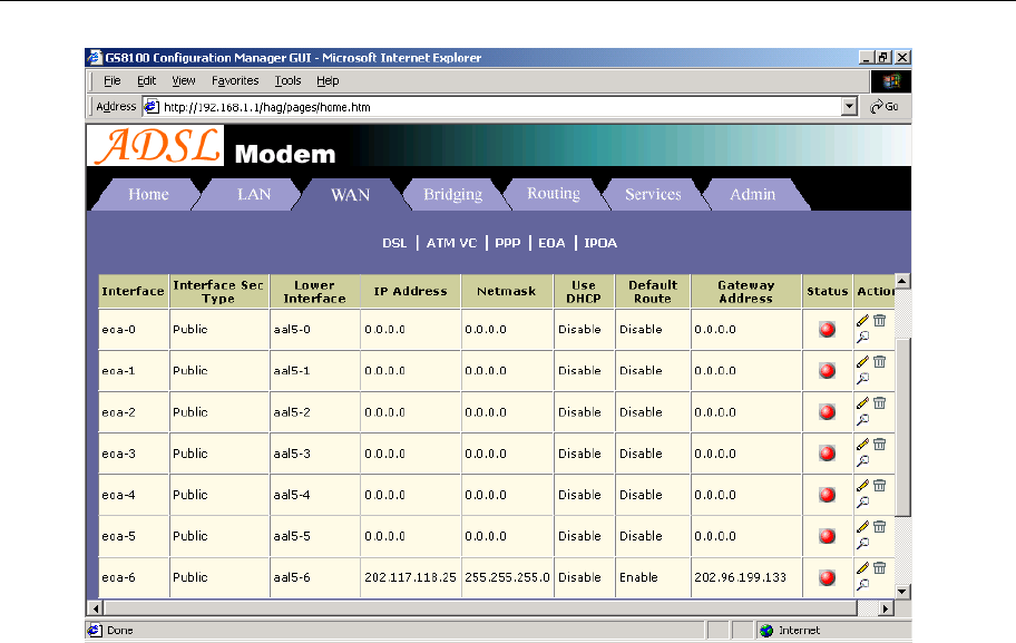
b) EOA configuration
− Only one PPP can be accepted by the MODEM as default router. So confirm there are no PPPs
in the “PPP” of Page “WAN”, shown as Figure 3.6.
− Click EOA label. The factory default configuration sets 6 EOAs (RFC1483 bridge). Add eoa-6
for example.
− Click “Add” button, the pop up window is shown as Figure 3.4
− Choose aal5-6 for Lower Interface option
− Choose enable for Default Route option
− Fill the IP address, IP subnet mask and gateway IP address items with the parameters provided
by DSL ISP. Here we will use “202.117.118.25”, “255.255.255.0” and “202.96.199.133” as
examples.
− Don’t change other options, click “Submit” button, and the result window is shown as Figure 3.7
Figure 3.6
ADSL MODEM USER MANUAL
- 14 -
Figure 3.7
c) Click “Commit & Reboot” label in Page Admin to access save configuration tools page, shown as
Figure 2.3. Click “Commit” button. Wait till this message “Changes Committed Successfully...”
appears. Click “Reboot” button or turn off and on power of the ADSL MODEM. The MODEM will
work on the new parameters.
2. RFC1577 configuration
a) ATM VC configuration
Use one of the factory default ATM VCs for example: aal5-6 (VPI=0, VCI=33)
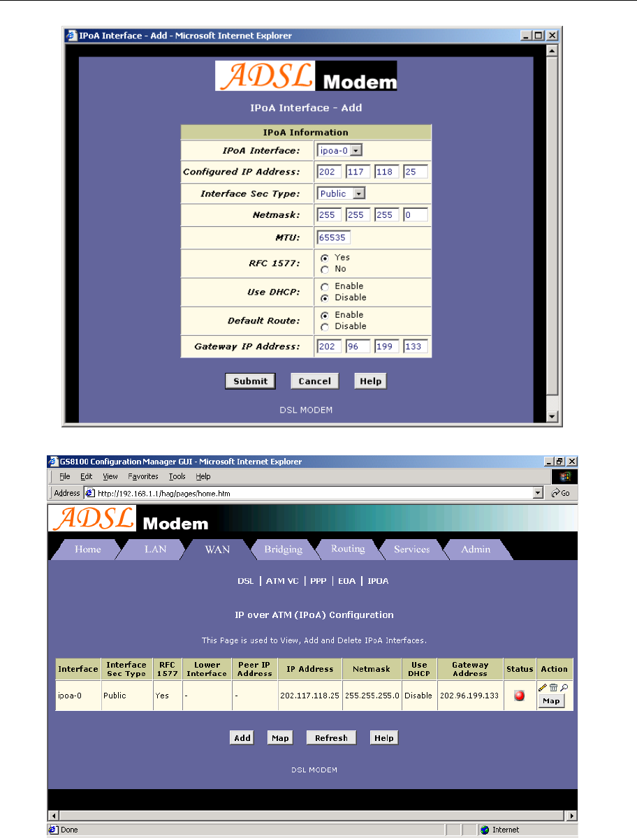
b) IPOA configuration
− Only one PPP can be accept by the MODEM as default route. So confirm there are no PPPs in
the “PPP” of Page “WAN”, shown as Figure 3.6.
− Click IPOA label. Add one IPOA ipoa-0 for example.
− Click “Add” button, the pop up window is shown as Figure 3.8.
− Choose 1577 for IPOA type option.
− Choose Enable for Default Route option.
− Fill in the IP address, IP subnet mask and gateway IP address items with the parameters provided
by DSL ISP. Here use “202.117.118.25”, “255.255.255.0” and “202.96.199.133” for example.
− Do not change other options, click “Submit” button, and the result window will be shown as
Figure 3.9
ADSL MODEM USER MANUAL
- 15 -
Figure 3.8
Figure 3.9
c) Click “Commit & Reboot” in Page Admin to access Save configuration tools page, shown as Figure
2.3. Click “Commit” button and wait till the message “Changes Committed Successfully...” appears.
Click “Reboot” button or turn off and on the power of the ADSL MODEM. The MODEM will work
on the new parameters.

ADSL MODEM USER MANUAL
- 16 -
3.4 PPPOA AND PPPOE CONFIGURATION
There are two methods for PPPOE configuration: 1483 bridge + third-party dialup software; Internal virtual
Dialup function in the MODEM.
1483 bridge + third-party dialup software
− Setup RFC1483 Bridge.
− Install third party dialup software such as Enternet300, WinPoet or RasPPPoE. For more detail
consult with the DSL ISP.
− Use the installed software to dial up.
Internal virtual Dialup function in the MODEM
1. ATM VC configuration
Use one of the factory set ATM VCs for example: aal5-0 (VPI=14, VCI=24)
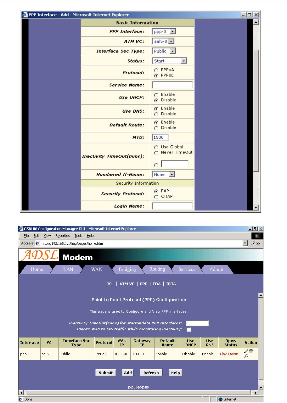
2. PPP configuration
− Click “PPP” label on the Page “WAN”.
− Click “Add” button, the pop up window is shown as Figure 3.10.
− Choose aal5-0 for the Lower Interface option.
− Choose Enable for DNS option.
− Fill in the User Name and Password provided by the DSL ISP.
− Do not change other options. Click “Submit” button, the result window is shown as Figure 3.11.
3. Click “Commit & Reboot” in Page “Admin” to access Save configuration tools page, shown as Figure
2.3. Click “Commit” button and wait till the message “Changes Committed Successfully...” appears.
Click “Reboot” button or turn off and on the power of the ADSL MODEM. The MODEM will work on the
new parameters.
ADSL MODEM USER MANUAL
- 17 -
Figure 3.10
Figure 3.11

ADSL MODEM USER MANUAL
- 18 -
4. APPLICATION OF DHCP
Apart from being a modem, ADSL Modem can also support router, DHCP and DNS applications, which
are especially applicable for small business, small scale LAN, net-café, etc.
The ADSL Modem can work as a router, DHCP sever and DNS sever without proxy server. The
configuration steps are shown below:
4.1 TCP/IP PROTOCOL CONFIGURATION
1. Set IP address as “Automatically obtain IP address”;
2. Set gateway’s IP the same as Modem’s;
3. Set DNS’s address at the Modem’s IP address or a valid DNS address.
4.2 MODEM CONFIGURATION
1. Set protocol as described in Chapter 3.
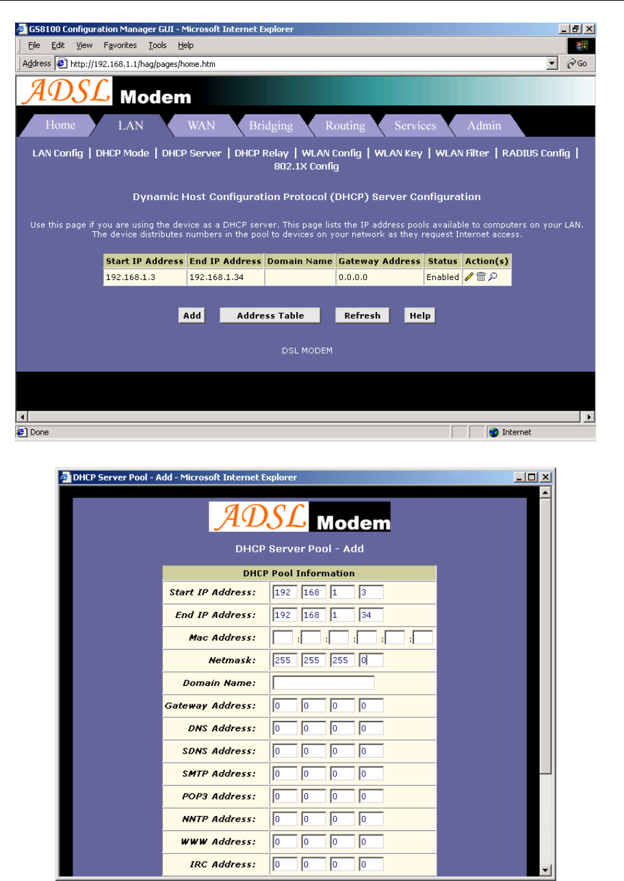
2. DHCP sever settings:
a) Click DHCP mode label of Page “LAN”. Choose DHCP sever for DHCP mode option. Then click
“Submit”.
b) Click
DHCP sever label to define DHCP starting and ending IP address, shown as Figure 4.2.
c) Click to delete current DHCP sever address pool.
d) If you want to add new DHCP sever address pool, click “Add” button, the pop up window is shown as
Figure 4.3.
e) Fill in the starting IP address, ending IP address and subnet mask IP address Items. Here we will use
192.168.1.3, 192.168.1.34 and 255.255.255.0 as an example.
f) Do not change other options. Click “Submit”, the result window is shown as Figure 4.2.
4
APPLICATION OF DHCP
ADSL MODEM USER MANUAL
- 19 -
Figure 4.2
Figure 4.3
ADSL MODEM USER MANUAL
- 20 -
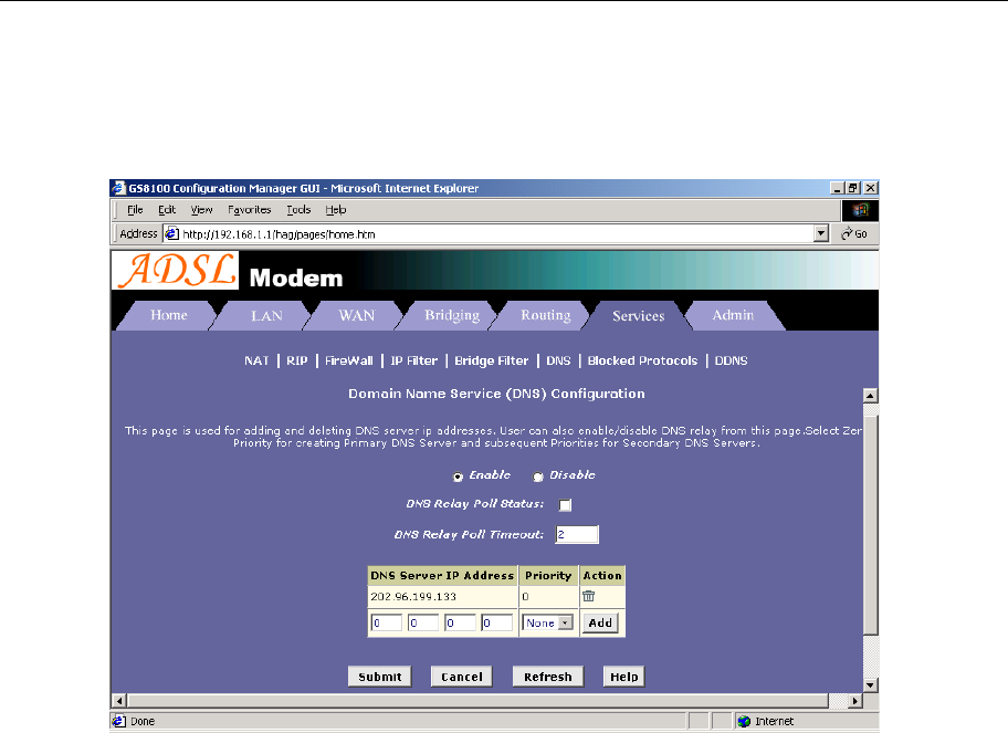
3. DNS settings:
Click DNS label of Page Services. Choose Enable option. Fill in the DNS sever IP address column with
the valid DNS sever IP address; here we use 202.96.209.5 and 202.96.209.133 for example. Click “Add”, the
result window is shown as Figure 4.4.
Figure 4.4
4. Click “Commit & Reboot” label in Page Admin to access Save configuration tools page, shown as Figure
2.3. Click “Commit” and wait till the message “Changes Committed Successfully...” appears. Click
“Reboot” or turn off and on the power of the ADSL MODEM. The MODEM will work on the new
parameters.
ADSL MODEM USER MANUAL
- 21 -
5. OTHER FUNCTIONS AND CONFIGURATION
5.1 STATUS CHECKING
The working status of ADSL MODEM can be monitored by some pages.
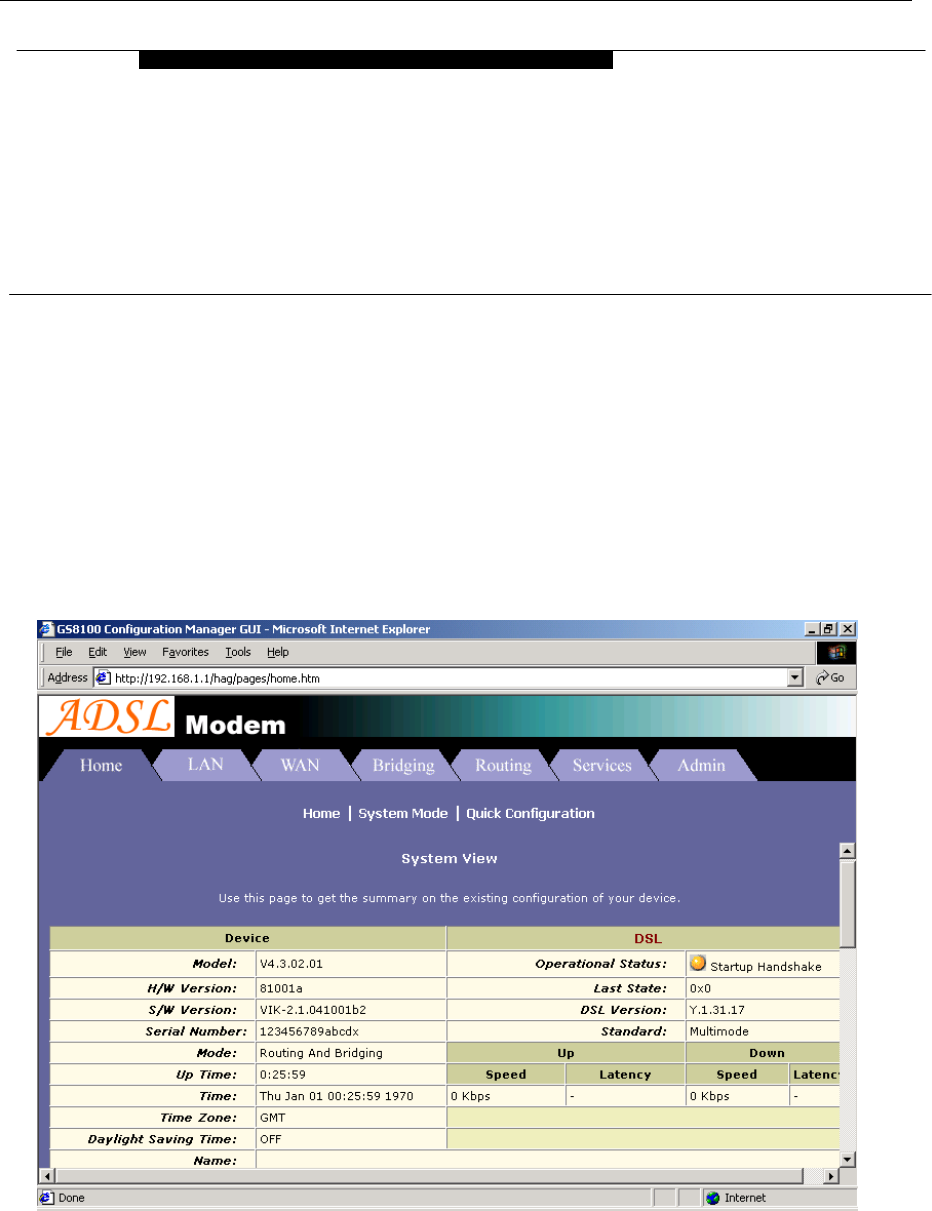
1. System Information
As shown in Figure 5.1, the information of hardware version, software version, DSL link status, link speed,
LAN interface and WAN interface can be viewed on this page.
Figure 5.1
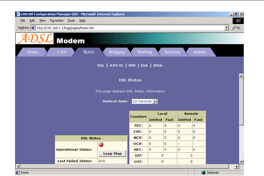
2. DSL Information
As shown in Figure 5.2, the line status of ADSL, duration, connection speed, signal noise ratio, power and
the line attenuation can be viewed on the Routing menu and DSL parameter page.
5
OTHER FUNCTIONS AND
CONFIGURATION
ADSL MODEM USER MANUAL
- 22 -
Figure 5.2
5.2 CONFIGURATION OF MODEM’S IP ADDRESS AND PASSWORD
1. CONFIGURATION OF MODEM’S IP ADDRESS
As a network device, ADSL Modem has its own IP address and MAC address. The factory sets the ADSL
Modem at a default IP address of 192.168.1.1 and subnet mask of 255.255.255.0. The user can configure these
addresses through the LAN configuration tab on page LAN.
2. Configuration of administrator’s password and user’s password
When logging on the setting page of ADSL Modem, the system requires user name and password to verify
for permission. The default administrator’s account is “admin” and the default password for this account is
“password”. The user, through the user configuration tab on page Admin, can change the passwords. (Attention:
please remember the password after changing otherwise you will not be able to change configuration after
saving.)
ADSL MODEM USER MANUAL
- 23 -
6. RESET TO DEFAULT SETTING
If you are experiencing difficulty logging on to the configuration page (For example: you forget the
password), you can reset the ADSL MODEM to the default configuration,Then you will be able to log on with
the default username and password.
Method:
Turn on the ADSL MODEM, put a pin into the eyelet, and press only once.
6
RESET TO DEFAULT SETTING

ADSL MODEM USER MANUAL
- 24 -
7. SPECIFICATION
7.1 POWER SUPPLY
Exterior power adapter
Input: 220VAC, 50Hz
Output: 5.2VDC,1000mA.
Polarity:
7.2 STANDARDS
EMI/Immunity: FCC Part 15 Class B, CE Mark (EN55022 Class B/EN50082)
Safety Standard: UL, EN60950, 3C
Communication: FCC Part 68, CYR21
Electromagnetic: in accordance with FCC, ETSI and CISPR standard
7.3 ENVIRONMENT REQUIREMENTS
Temperature: 5℃-40℃(41F-104F)
Relative humidity:0%-95%
Electromagnetic disturbance:FCC PART15&68
7
SPECIFICATION

ADSL MODEM USER MANUAL
- 25 -
APPENDIX
APPENDIX A. TROUBLESHOOTING
Phenomena Solution
The indicator of power
supply is not on
1. Make sure the connection of power supply is good.
2. Make sure the switch of power supply is turned on.
3. Make sure the output of power supply is correct.
The indicator of PC is not
on
1. Check the connection between the cable and the network card.
2. Make sure that the correct cable is used.
3. Make sure the cable works fine by pinging the host IP address.
Can not access Internet or
remote networks
1. Make sure the problems listed above are eliminated.
2. Make sure the software configuration of the ADSL Modem is
correct.
3. Make sure you have restarted the ADSL Modem after
configuration change.
4. Check IP connection using ping command.
5. Make sure the DNS of the computer is correct.
Can’t access some web
server
1. The MTU of operating system might be too large.
2. Some operating systems might need to be patched.
Can not log on to the
configuration page
1. Make sure the PC indicator is on.
2. Make sure the configuration of TCP/IP is correct.
3. Make sure the data indicator of Modem is on when using Ping
command.
4. Make sure the user name and password is correct.
5. Reset the device.
8
APPENDIX
ADSL MODEM USER MANUAL
- 26 -
APPENDIX B. SPLITTER CONNECTION
1. Splitter
2. Connection
Firstly, use a telephone cord to connect the LINE port of the splitter and the RJ-11 port (the phone jack) on
the wall. Then use another telephone cord to connect the ADSL port of the splitter and the LINE port of the
ADSL Modem. Finally, use another telephone cord to connect the telephone set and the PHONE port of the
splitter.
Power
Interface Line
Interface
Ethernet
Interface
ADSL MODEM USER MANUAL
- 27 -
APPENDIX C. CONFIGURATION OF TCP/IP PROTOCOL
Here we will explain the configuration which using Windows 2000 operation system as an example.
For other operation systems the process is similar.
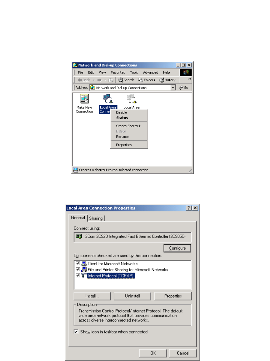
1. Right click on the “Local Area Connection”, click “Properties” on the pop up menu, as shown in Figure
C.1.
Figure C.1
2. The dialog box of networks is shown in Figure C.2. On the “General” property page select “Internet
Protocol(TCP/IP)”,and then click the “Properties” button.
Figure C.2
ADSL MODEM USER MANUAL
- 28 -
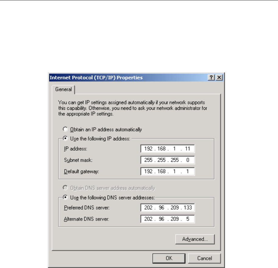
3. The “Internet Protocol (TCP/IP) properties” pop up window is shown as Figure C.3. Select “Use the
following IP address”. Input the following IP address: 192.168.1.11 and subnet mask: 255.255.255.0
(These addresses and subnet mask are similar with the factory default setting. The user can set different IP
addresse and subnet mask whenever necessary). Select “Gateway”, input the default IP address of the
gateway: 192.168.1.1 and IP address of Preferred DNS server: 202.96.209.133 (you can use your ISP’s
address), IP address of Alternate DNS server: 202.96.209.5(you can use your ISP’s address). The result is
shown in Figure C.3.
Figure C.3
4. Click “OK” button to return to the “Local Area Connection Property” dialog box.
5. Click “OK” button to close the Network property dialog box.

ADSL MODEM USER MANUAL
- 29 -
APPENDIX D. SHIPPING LIST
Make sure the following items are included in the box. If any one of them is missing, please
contact the vendor immediately.
ADSL MODEM
×1
User Manual ×1
TelephoneLine(RJ-11) ×2
Power Adapter ×1
Cable Cat5 RJ45 ×1
Splitter ×1

ADSL MODEM USER MANUAL
- 30 -
Please use the factory recommended
power supply.

ADSL MODEM USER MANUAL
- 31 -
FCC Warning:
Note: This equipment has been tested and found to comply with the limits for a Class B digital device,
pursuant to part 15 of the FCC Rules. These limits are designed to provide reasonable protection
against harmful interference in a residential installation. This equipment generates, uses and can
radiate radio frequency energy and, if not installed and used in accordance with the instructions, may
cause harmful interference to radio communications. However, there is no guarantee that interference
will not occur in a particular installation. If this equipment does cause harmful interference to radio or
television reception, which can be determined by turning the equipment off and on, the user is
encouraged to try to correct the interference by one or more of the following measures:
—Reorient or relocate the receiving antenna.
—Increase the separation between the equipment and receiver.
—Connect the equipment into an outlet on a circuit different from that to which the receiver is
connected.
—Consult the dealer or an experienced radio/TV technician for help.
Modifications not authorized by the manufacturer may void users authority to operate this device.
This device complies with part 15 of the FCC Rules. Operation is subject to the following two
conditions: (1) This device may not cause harmful interference, and (2) this device must accept any
interference received, including interference that may cause undesired operation.