Data Critical 02DR-10110 WMTS OPENNET LAN User Manual 06 10001003 004 B
Data Critical Corporation WMTS OPENNET LAN 06 10001003 004 B
Contents
- 1. Manual admin guide
- 2. Manual user guide
- 3. Installer note
Manual admin guide
WMTS OPENNET LAN PROGRAMMING AND DIAGNOSTICS
PatientNet Administrator’s Guide, v1.04, 10001003-004, Revision B 101
All information contained herein is subject to the rights and restrictions on the title page.
WMTS OPENNET LAN PROGRAMMING AND DIAGNOSTICS
Note: The information in this section is only applicable for Wireless Medical
Telemetry Service (WMTS) version of PatientNet.
About this Section
This section includes instructions for the following tasks:
• defining the Device Master (page 103)
• viewing OpenNet diagnostics (page 116)
• configuring the OpenNet LAN (page 104)
• setting Access Point parameters (page 106)
• assigning transceivers (page 135)
Accessing the OpenNet LAN screen
To access the OpenNet LAN screen:
1. Access the Service Screen (page 63).
2. Click the Service button on the System Setup screen.
3. Click the OpenNet button on the Service screen to open the OpenNet LAN
screen. If the OpenNet LAN is not enabled on your system, then the OpenNet
Status screen (page 136) will display instead of the OpenNet LAN screen.
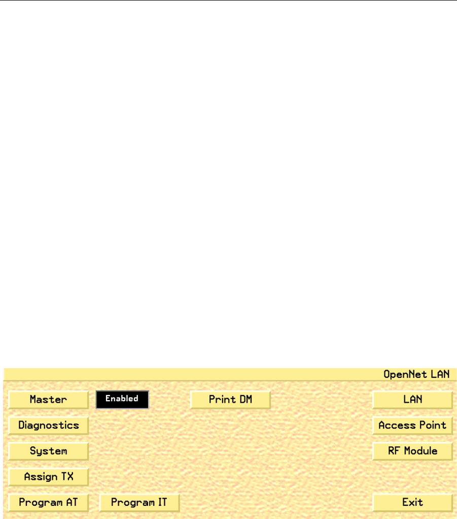
Fig. 60. OpenNet LAN Screen
4. Click the Exit button to close the OpenNet LAN screen and return to the
Service screen.

WMTS OPENNET LAN PROGRAMMING AND DIAGNOSTICS
102 PatientNet Administrator’s Guide, v1.04, 10001003-004, Revision B
All information contained herein is subject to the rights and restrictions on the title page.
Description of Buttons and Functions
The following section describes the buttons and functions of the OpenNet LAN
Screen. Subsequent sections will discuss each function in detail.
Button Function
Master Designates the system as the Device Master, which controls the user defined
parameters on systems throughout the OpenNet LAN (page 103).
Diagnostics Displays the OpenNet Diagnostics screen (page 116).
System Displays the OpenNet System Configuration screen (page 104).
Assign TX Displays the Assign Transceiver screen. (page 135)
Program AT Displays the Ambulatory Transceiver (AT), programming screen.
(page 123). See the Programming Transceivers (page 122) section for
details.
Program IT Displays the Instrument Transceiver (IT), programming screen. (page 129).
See Programming Transceivers (page 122) for details.
Print DM Prints the Device Master report, which displays the global, as well as indi-
vidual, parameters for each Access Point.
LAN Displays the OpenNet LAN Configuration screen, which is allows you to set
the OP Band, Ext Sync, and update Access Points (page 104).
• This button is only available on the Device Master system.
Access Point Displays the Access Point Settings screen, which allows you to configure the
Access Point settings (page 106).
• This button is only available on the Device Master system.
RF Module Displays the RF Module screen, which allows you to configure the RF Mod-
ule settings (page 111).
• This button is only available on the Device Master system.

WMTS OPENNET LAN PROGRAMMING AND DIAGNOSTICS
PatientNet Administrator’s Guide, v1.04, 10001003-004, Revision B 103
All information contained herein is subject to the rights and restrictions on the title page.
Designating a Device Master
The Device Master is the system on the OpenNet LAN that controls the user defined
parameters.
To designate the system as the Device Master:
1. Click the Master button to toggle between Enabled and Disabled (see fig. 60
on page 101).
• Selecting Enabled defines the system as the Device Master.
Note: Only one Device Master is allowed on the network at one time. To enable a
new Device Master, you must first disable the original Device Master, then
enable the new Device Master.
• Selecting Disabled defines the system as not being the Device
Master.
2. Click the Exit button to close the OpenNet LAN screen and return to the
Service screen.
Printing the Device Master Report
The Device Master Report displays the global, as well as individual, parameters for
each Access Point.
To print the Device Master Report:
1. Click the Print DM button on the OpenNet LAN screen to print the Device
Master Report.
2. Click the Exit button to close the OpenNet LAN screen and return to the
Service screen.
WMTS OPENNET LAN PROGRAMMING AND DIAGNOSTICS
104 PatientNet Administrator’s Guide, v1.04, 10001003-004, Revision B
All information contained herein is subject to the rights and restrictions on the title page.
Configuring the Device Master
You can configure global parameters for the Device Master in the OpenNet LAN Con-
figuration screen.
To configure the OpenNet LAN parameters:
Note: In order to view the LAN button, the Central Station must be designated as
the device master (see “Designating a Device Master” on page 103).
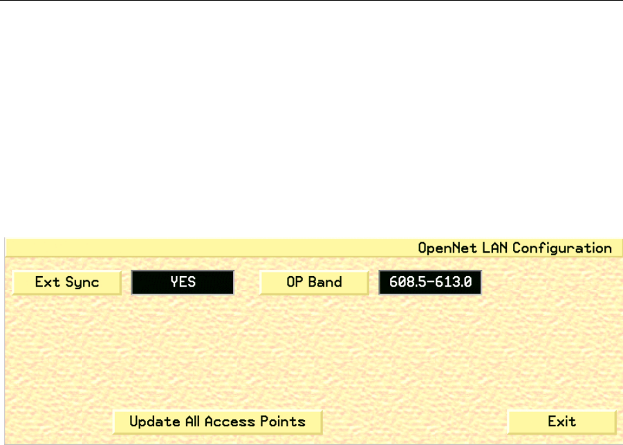
1. Click the LAN button to open the OpenNet LAN Configuration screen (fig.
61).
Fig. 61. OpenNet LAN Configuration Screen
2. Click the Ext Sync button to toggle the Access Point synchronization source
between Yes and No.
• Selecting Yes will designate an external source for providing the synchroni-
zation of each Access Point.
• Selecting No will designate a single Access Point the task of providing its
own synchronization.
Note: You can only set the Ext Sync to No for a single Access Point system.

WMTS OPENNET LAN PROGRAMMING AND DIAGNOSTICS
PatientNet Administrator’s Guide, v1.04, 10001003-004, Revision B 105
All information contained herein is subject to the rights and restrictions on the title page.
3. Click the OP Band button to set the operating band that will be used by the
Access Point.
• Typically, the 608.5-613.0 OP Band is selected. However, where the Patient-
Net System operates in the same hospital as another system (or systems) that
also use(s) the 608-614 MHz WMTS band, it will be necessary to select one
of the sub-bands. The sub-band should coordinate with the hospital’s spec-
trum policy.
• Additional sub-bands include: 608.5-609.7, 609.6-610.8, 610.7-611.9, and
611.8-613.0
WARNING: All transceivers must be programmed to the same OP Band as the Access
Points. This is an administrative procedure only. Do not attempt to program
the transceivers with the selected OP Band.
4. Click the Update All Access Points button to update any allocated Access
Points on the OpenNet LAN with the current configuration data from the
Device Master.
WARNING: Selecting Update All Access Points will re-configure all Access Points on the
network and will affect proper system operation. Do not activate this button
on a live system.
5. Click the Exit button to close the OpenNet LAN Configuration screen and
return to the OpenNet LAN screen.
WMTS OPENNET LAN PROGRAMMING AND DIAGNOSTICS
106 PatientNet Administrator’s Guide, v1.04, 10001003-004, Revision B
All information contained herein is subject to the rights and restrictions on the title page.
Setting Access Point Parameters
You can view and edit the settings for all Access Points on the network with the
Access Point Settings screen.
To view and edit Access Point settings:
Note: In order to view the Access Point button, the system must be designated as
the device master (see “Designating a Device Master” on page 103).
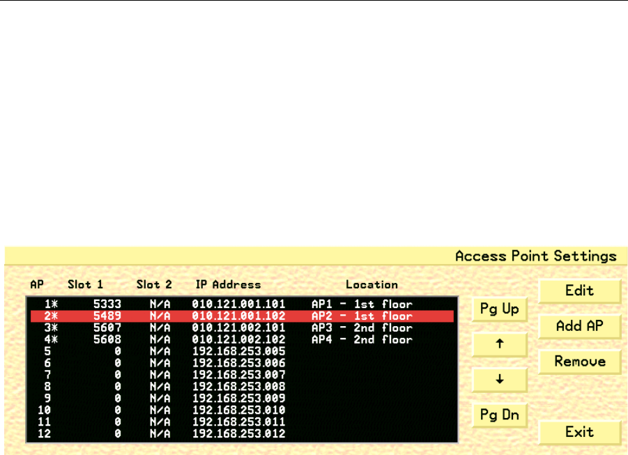
1. Click the Access Point button on the OpenNet LAN screen to open the
Access Point Settings screen (fig. 62).
Fig. 62. Access Point Settings Screen
2. Click the Pg Up, Pg Dn, and arrow buttons to select each Access Point and
view its current settings.
3. Click the Edit button to open the Access Point Configuration screen (see
“Configuring Access Point Parameters” on page 108). This will allow you to
change the selected Access Point’s parameters.
4. Click the Add AP button to open the Access Point Configuration screen and
configure the settings for the next available Access Point in sequence (see
“Configuring Access Point Parameters” on page 108).
5. Click the Remove button to remove a selected Access Point from the Access
Point Settings screen and the OpenNet LAN.
• A warning popup will display requesting you to click either Yes, which will
remove the selected Access Point, or No, which will close the popup and
leave the Access Point unchanged.

WMTS OPENNET LAN PROGRAMMING AND DIAGNOSTICS
PatientNet Administrator’s Guide, v1.04, 10001003-004, Revision B 107
All information contained herein is subject to the rights and restrictions on the title page.
6. Click the Exit button to close the Access Point Settings screen and return to
the OpenNet LAN screen.
The columns in the Access Point Settings screen are described below
AP displays the access point for each configured RF Module on the Open-
Net LA.
Note: An asterix (*) next to the AP number indicates that the Access Point
is active in the Device Master.
Slot 1 displays the 24 bit ID number for the RF Module that is located in the
first slot of the Access Point
Slot 2 displays the 24 bit ID number for the RF Module that is located in the
second slot of the Access Point
IP Address displays the IP address for an Access Point
Location displays each Access Point’s location.
WMTS OPENNET LAN PROGRAMMING AND DIAGNOSTICS
108 PatientNet Administrator’s Guide, v1.04, 10001003-004, Revision B
All information contained herein is subject to the rights and restrictions on the title page.
Configuring Access Point Parameters
You can configure the parameters for each Access Point on the OpenNet LAN with
the Access Point Configuration screen. This screen also allows you to configure the
parameters for Access Points that have been added to the network.
To configure Access Point parameters:
Note: In order to view the Access Point button, the system must be designated as
the device master (see “Designating a Device Master” on page 103).
1. Click the Access Point button on the OpenNet LAN screen to open the
Access Point Settings screen (see fig. 62 on page 106).
2. Select the Access Point that you would like to configure and click the Edit
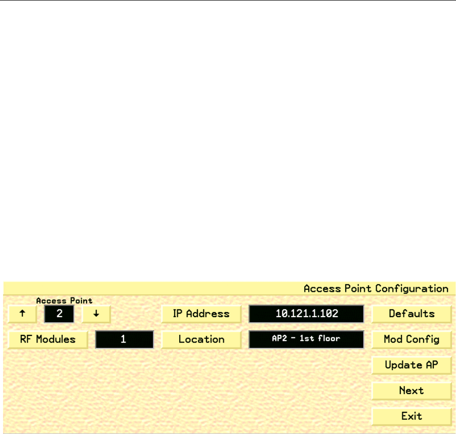
button to open the Access Point Configuration screen (fig. 63).
Note: Clicking the Add AP button on the Access Point Settings screen displays
the Access Point Configuration screen for the next available, currently
unassigned, Access Point on the system. This allows you to configure and
add the new AP to the system.
Fig. 63. Access Point Configuration Screen
3. Select the desired Access Point number by clicking the up and down arrows,
which will cycle through the available Access Points and update the fields
with settings for each selected Access Point.
4. Click the RF Modules button to toggle the RF Module setting between 1 and
2. The RF Module setting defines the number of RF Modules that reside in the
selected Access Point.
5. Click the IP Address button to open a keypad with which you can set the IP
address for the selected Access Point.

WMTS OPENNET LAN PROGRAMMING AND DIAGNOSTICS
PatientNet Administrator’s Guide, v1.04, 10001003-004, Revision B 109
All information contained herein is subject to the rights and restrictions on the title page.
6. Click the Location button to open the Location popup (fig. 64), which allows
you to enter the Access Point’s location
Fig. 64. Access Point Default Location Popup
7. Click the Defaults button to return the selected Access Point’s settings to the
system default configuration.
8. Click the Mod Config button to open the RF Module Configuration screen
(see “Configuring RF Module Parameters” on page 113), which allows you to
configure the RF Module for the selected Access Point.
9. Click the Update AP button to update the selected Access Point device with
the new configuration data.
Note: During the Update process, the Access Point will not be active.
10. Click the Next button to display the Access Point Configuration Page 2 screen
(page 110).
11. Click the Exit button to close the Access Point Configuration screen and
return to the Access Point Settings screen.
WMTS OPENNET LAN PROGRAMMING AND DIAGNOSTICS
110 PatientNet Administrator’s Guide, v1.04, 10001003-004, Revision B
All information contained herein is subject to the rights and restrictions on the title page.
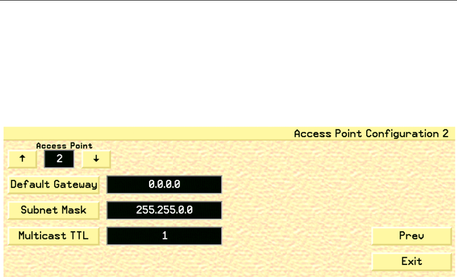
Configuring Access Point Parameters - Part 2
The second page of the Access Point Configuration screen allows you to configure
additional Access Point parameters.
1. Click the Next button on the Access Point Configuration screen (see “Access
Point Configuration Screen” on page 108) to open the Access Point Configu-
ration Page 2 screen (page 110).
Fig. 65. Access Point Configuration Screen - Part 2
2. Select the desired Access Point number by clicking the up and down arrows,
which will cycle through the available Access Points and update the fields
with settings for each selected Access Point.
3. Click the Default Gateway button to open a keypad that allows you to set a
valid gateway address for the selected Access Point. This button is for admin-
istrative purposes only. Do not attempt to set the Default Gateway.
4. Click the Subnet Mask button to open a keypad with which you can enter the
OpenNet LAN subnet mask for the system. This button is for administrative
purposes only. Do not attempt to set the Subnet Mask.
5. Click the Multicast TTL button to open a keypad that allows you to set a
valid Mulitcast Time to Live (TTL) for the selected Access Point. Valid
values are between 1 and 255. Set the Multicast TTL to 1 unless instructed to
do otherwise. This button is for administrative purposes only. Do not attempt
to set the Multicast TTL.
6. Click the Prev button to return to the Access Point Configuration screen
(page 108).
7. Click the Exit button to close the Access Point Configuration screen and
return to the Access Point Settings screen.
WMTS OPENNET LAN PROGRAMMING AND DIAGNOSTICS
PatientNet Administrator’s Guide, v1.04, 10001003-004, Revision B 111
All information contained herein is subject to the rights and restrictions on the title page.
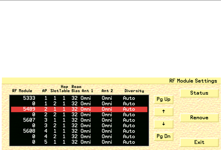
Configuring RF Modules
You can view the current RF Module configurations for each Access Point on the net-
work with the RF Module Settings screen.
To view RF Module settings:
1. Access the OpenNet LAN screen (page 101).
2. Click the RF Module button to open the RF Module Settings screen (fig. 66),
or you can click the Mod Config button on the Access Point Configuration
screen (see “Configuring Access Point Parameters” on page 108).
Fig. 66. RF Module Settings
3. Click the Status button to open the RF Module Status screen (see fig. 67 on
page 112), which allows you to view the current status of each RF Module in
the blackboard.
4. Click the Remove button to remove a selected RF Module from the RF Mod-
ule Settings screen and the OpenNet LAN.
• A warning popup will display requesting you to click either Yes, which will
remove the selected RF Module, or No, which will close the popup and leave
the RF Module unchanged.
5. Click the Exit button to close the RF Module Settings screen and return to the
OpenNet LAN screen.
WMTS OPENNET LAN PROGRAMMING AND DIAGNOSTICS
112 PatientNet Administrator’s Guide, v1.04, 10001003-004, Revision B
All information contained herein is subject to the rights and restrictions on the title page.
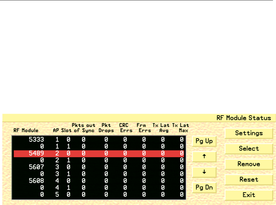
Viewing RF Module Status
Clicking the Settings and Status buttons will allow you to toggle between the RF
Module Settings and RF Module Status screens. The RF Module Status screen allows
you to view the current status of each RF Module on the RF Module Settings black-
board.
To view the status of each RF Module:
1. Access the RF Module Settings screen (see “Configuring RF Modules” on
page 111).
2. Click the Status button on the RF Module Settings screen to open the RF
Module Status screen (fig. 67).
Fig. 67. RF Module Status Screen
3. Click the Settings button to return to the RF Module Settings screen.
4. Use the Pg Up, Pg Dn, and arrow buttons to select a RF Module to configure.
5. Once you have highlighted (selected) a RF Module, click the Select button to
open the RF Module Configuration screen (see “Configuring RF Module
Parameters” on page 113). The blackboard reflects the current RF Module
configurations.
6. Click the Remove button to remove a selected RF Module from the RF Mod-
ule Settings screen and the OpenNet LAN.
• A warning popup will display requesting you to click either Yes, which will
remove the selected RF Module, or No, which will close the popup and leave
the RF Module unchanged.
7. Click the Reset button to return the status blackboard values to zero.
8. Click the Exit button to close the RF Module Status screen and return to the
OpenNet LAN screen.
WMTS OPENNET LAN PROGRAMMING AND DIAGNOSTICS
PatientNet Administrator’s Guide, v1.04, 10001003-004, Revision B 113
All information contained herein is subject to the rights and restrictions on the title page.
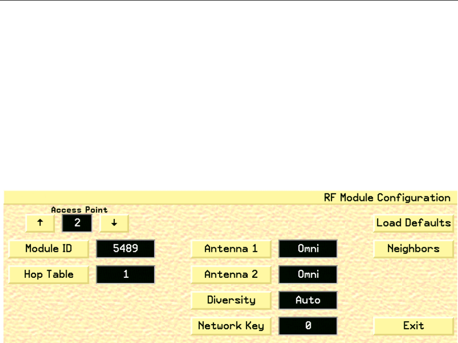
Configuring RF Module Parameters
You can configure the parameters for each RF Module on each Access Point that is on
the OpenNet Network with the RF Module Configuration screen.
To configure RF Module parameters:
1. Access the OpenNet LAN screen (page 101).
2. Access the RF Module Settings screen (page 111), highlight the RF Module
that you would like to configure, and click the Select button on the RF Mod-
ule Status screen to open the RF Module Configuration screen (fig. 68).
• From the Access Point Configuration screen (page 108), click the
Mod Config button to access the RF Module Configuration screen (fig. 68).
Fig. 68. RF Module Configuration Screen
3. Select the desired Access Point number by clicking the up and down arrows,
which will cycle through the available Access Points and update the fields
with the settings for each Access Point.
4. Click the Module ID button to open a keypad that allows you to set the RF
Module’s 24 bit identification number.
5. Click the Hop Table button to define the hop table for the RF Module. The
available values are 0 to 31.
6. Click Antenna 1 button to cycle through the available antenna types for the
first RF Module. The available antennas consist of the
following:
• Omni (always select Omni)
• Patch (future release)
• Peanut (future release)

WMTS OPENNET LAN PROGRAMMING AND DIAGNOSTICS
114 PatientNet Administrator’s Guide, v1.04, 10001003-004, Revision B
All information contained herein is subject to the rights and restrictions on the title page.
7. Click Antenna 2 button to cycle through the available antenna types for the
RF Module. The available antennas consist of the
following:
• Omni (always select)
• Patch (future release)
• Peanut (future release)
8. Click the Diversity button to define the diversity setting for both antenna 1
and 2. The available settings consist of the following:
a. Antenna 1
Auto
Ant A1
Ant A2
b. Antenna 2
Auto
Ant B1
Ant B2
Note: Select Auto unless instructed to do otherwise.
9. Click the Network Key button to open a keypad that allows you to set the
network key for the RF Module. The Network key values can be set from 0 to
255.
WARNING: All Access Points must be programmed to the same Network Key as the
transceivers. This is an administrative procedure only. Do not attempt to pro-
gram the Access Points with the Network Key.
Note: The Network key can be configured for each module slot.
10. Click the Load Defaults button to return the RF Module parameters to their
default values.
11. Click the Neighbors button to open the RF Module Neighbors Configuration
screen (see “Configuring RF Module Neighbors” on page 115).
12. Click the Exit button to close the RF Module Configuration screen and return
to the RF Module Status screen.
WMTS OPENNET LAN PROGRAMMING AND DIAGNOSTICS
PatientNet Administrator’s Guide, v1.04, 10001003-004, Revision B 115
All information contained herein is subject to the rights and restrictions on the title page.
Configuring RF Module Neighbors
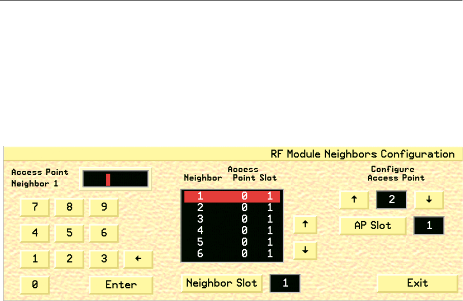
You can configure up to eight neighbors for each RF Module in each configured
Access Point on the OpenNet LAN.
To configure the neighbors of a RF Module:
1. Access the RF Module Configuration screen (page 113).
2. Click the Neighbors button on the RF Module Configuration screen to open
the RF Module Neighbors Configuration screen (fig. 69).
Fig. 69. RF Module Neighbors Configuration Screen
3. To assign a neighbor to the currently selected Access Point, type in the num-
ber of the Neighbor Access Point with the displayed keypad. The Neighbor
Access Point number will then appear in the blackboard under the Access
Point column.
4. Use the up and down arrows to highlight and select the Access Point Neigh-
bor that you would like to configure.
5. Click the Neighbor Slot button to define the desired slot, either 1 or 2, of the
selected access point’s neighbor.
• Only Access Point slots that have already been configured on the OpenNet
LAN can be selected as a Neighbor slot. Only Neighbor Slot 1 is currently
available.
6. Click the up and down arrows under the Configure Access Point heading to
define which Access Point is currently selected.
• Only Access Point that have already been configured on the OpenNet LAN
can be selected.
7. Click the AP Slot button to select the desired slot of the selected Access
Point. Only AP Slot 1 is currently available.
8. Click the Exit button to close the RF Module Neighbors Configuration screen
and return to the RF Module Configuration screen.
WMTS OPENNET LAN PROGRAMMING AND DIAGNOSTICS
116 PatientNet Administrator’s Guide, v1.04, 10001003-004, Revision B
All information contained herein is subject to the rights and restrictions on the title page.
Viewing OpenNet LAN Diagnostics
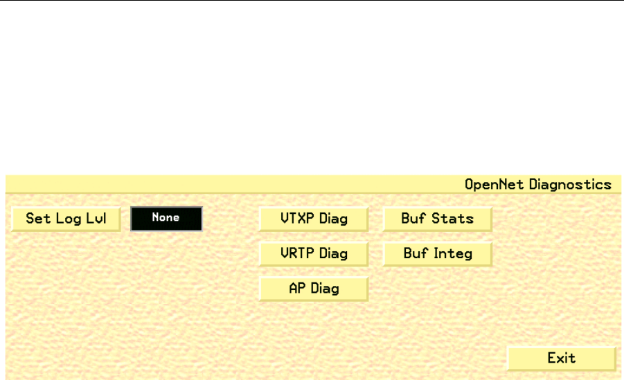
You can view, and configure, the OpenNet LAN Diagnostics on the OpenNet Diag-
nostics screen.
To View the OpenNet LAN Diagnostics:
1. Click the Diagnostics button on the OpenNet LAN screen to open the Open-
Net Diagnostics screen (fig. 70).
Fig. 70. OpenNet Diagnostics Screen
2. Click the Set Log Lvl button to toggle through the valid Set Log Level set-
tings. The set level defines the logging event criteria for the OpenNet LAN
diagnostic network for a Central Station. The options are None, Fatal, Error,
Warning, Info, and Debug.
WARNING: This button is for administrative purposes only. Do not attempt to set the Log
Level.
Note: This feature is only available for the Admin Administration level.
3. Click the Buf Stats button to check the buffer status by outputting the buffer
status to the mlog utility. This button is for administrative purposes only.
Note: The Set Log Lvl field must be set to a value other than None in order for the
status to be sent.
4. Click the Buf Integ button to check the buffer integrity by outputting the
buffer status to the mlog utility. The setting will output the data if the buffer
integrity is questionable. This button is for administrative purposes only.
Note: The Set Log Lvl field must be set to a value other than None in order for the
status to be sent.
WMTS OPENNET LAN PROGRAMMING AND DIAGNOSTICS
PatientNet Administrator’s Guide, v1.04, 10001003-004, Revision B 117
All information contained herein is subject to the rights and restrictions on the title page.
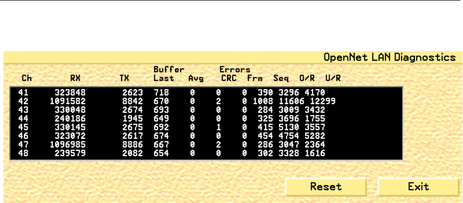
5. Clicking the VTXP Diag button will open the VTXP Diagnostics screen (fig.
71).
Fig. 71. VTXP Diagnostics Screen
The columns in the VTXP Diagnostics screen are described below.
Ch channel number
RX the number of good VTXP packets that have been received for each
channel
TX the number of good VTXP packets that have been transmitted to each
channel
Buffer Last displays the number of bytes that were contained in the last good
received VTXP packet for each channel
Buffer Avg displays the running average for the received buffer for each channel
Errors CRC displays the number of VTXP CRC errors detected for each channel
Errors FRM displays the number of VTXP frame errors detected for each channel
SEQ displays the number of VTXP sequence errors detected for each channel
O/R displays the number of over run errors detected for each channel
U/R displays the number of under run errors detected for each channel
Reset the Reset button will return each statistical value to zero
Exit the Exit button returns you to the OpenNet Diagnostics screen
WMTS OPENNET LAN PROGRAMMING AND DIAGNOSTICS
118 PatientNet Administrator’s Guide, v1.04, 10001003-004, Revision B
All information contained herein is subject to the rights and restrictions on the title page.
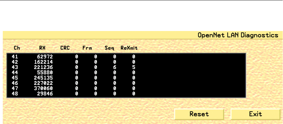
6. Clicking the VRTP Diag button will open the VRTP Diagnostics screen for
each Central Station (fig. 72).
Fig. 72. VRTP Diagnostics Screen
The columns in the VRTP Diagnostic screen are described below.
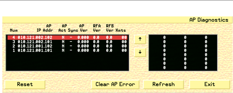
7. Clicking the AP Diag button will open the Access Point Diagnostic screen for
each Central Station (fig. 73).
Ch channel number
RX the number of VRTP packets that have been received for each channel
CRC displays the number of VRTP CRC errors detected for each channel
FRM displays the number of VRTP frame errors detected for each channel
SEQ displays the number of VRTP sequence errors detected for each channel
ReXmit displays the number of VRTP re-transmissions that were detected for
each channel
Reset the Reset button will return each statistical value to zero
Exit the Exit button returns you to the OpenNet Diagnostics screen
WMTS OPENNET LAN PROGRAMMING AND DIAGNOSTICS
PatientNet Administrator’s Guide, v1.04, 10001003-004, Revision B 119
All information contained herein is subject to the rights and restrictions on the title page.
Fig. 73. AP Diagnostics Screen
The columns on the left side of the AP Diagnostic blackboard screen are described
below.
The buttons in the AP Diagnostic screen are described below.
8. Click the Exit button to close the OpenNet Diagnostics screen and return to
the OpenNet LAN screen.
Num displays the Access Point number in the Device Master database that is
associated with the data
IP Address displays the IP address for a given Access Point
AP Act displays the Access Point active state: Y = Yes, N = No
AP Sync displays the Access Point sync state: Y = Yes, N = No sync detected
• a dash (-) is displayed when an AP is not active.
AP Ver displays the firmware version for each Access Point
RFA Ver displays the RF Module A firmware for each Access Point
RFB Ver displays the RF Module B firmware for each Access Point
(this function will be available in future software release)
Xmts displays the number of transceivers that are currently attached to the
Access Point
Blackboard displays the transceiver IDs for all transceivers attached to each Access
Point. Use the up and down arrows to navigate through the listed IDs
Refresh this button will refresh all Access Point active and sync status values
with the current values that are received from each Access Point
Clear AP
Error
this button will clear the currently active VRTP Protocol error
Reset this button clears the blackboard, requests all Access Points to identify
themselves, updates their status, and displays the received status infor-
mation on the blackboard
• Allow at least 1 minute for large systems reset
Exit the Exit button returns you to the OpenNet Diagnostics screen
WMTS OPENNET LAN PROGRAMMING AND DIAGNOSTICS
120 PatientNet Administrator’s Guide, v1.04, 10001003-004, Revision B
All information contained herein is subject to the rights and restrictions on the title page.
Configuring the OpenNet System
You can configure the OpenNet LAN parameters that are specific to each WMTS
Central Station with the OpenNet System Configuration screen.
To configure the OpenNet system:
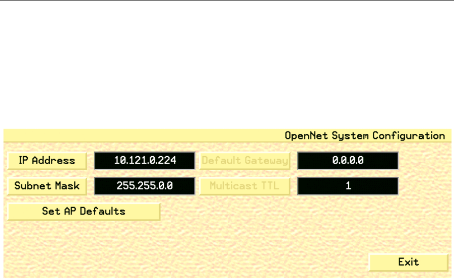
1. Click the System button on the OpenNet LAN screen to open the OpenNet
System Configuration screen (fig. 74).
Fig. 74. OpenNet System Configuration Screen
2. Click the IP Address button to open a keypad with which you enter the Open-
Net LAN IP address for the system.
3. Click the Subnet Mask button to open a keypad with which you can enter the
OpenNet LAN subnet mask for the system.
4. The Default Gateway button will be available in future releases.
5. The Multicast TTL button will be available in future releases.
6. Click the Set AP Defaults button to open the Access Point Default Configu-
ration screen (see “Configuring Access Point Defaults” on page 121).
7. Click the Exit button to close the OpenNet System Configuration screen and
return to the OpenNet LAN screen.
WMTS OPENNET LAN PROGRAMMING AND DIAGNOSTICS
PatientNet Administrator’s Guide, v1.04, 10001003-004, Revision B 121
All information contained herein is subject to the rights and restrictions on the title page.
Configuring Access Point Defaults
You can configure the default settings for all Access Points in the Access Point
Default Configuration screen.
To configure Access Point defaults:
1. Access the OpenNet System Configuration screen (page 120).
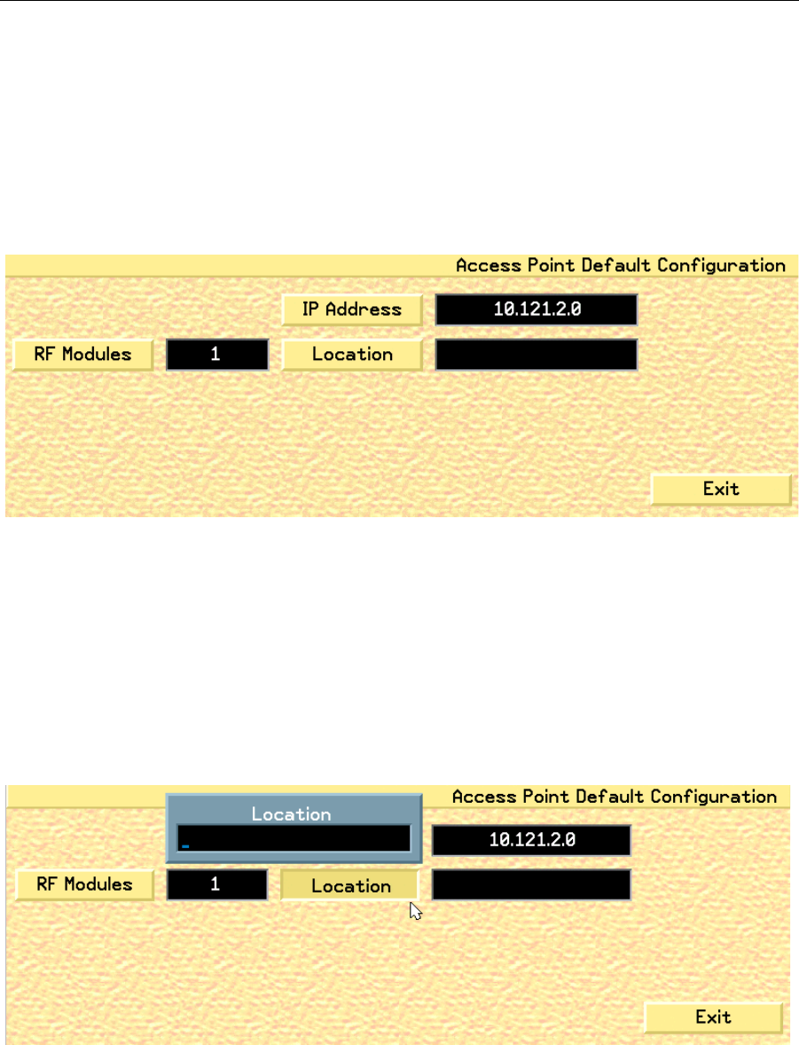
2. Click the Set AP Defaults button to open the Access Point Default Configu-
ration screen (fig. 75).
Fig. 75. Access Point Default Configuration Screen
3. Click the RF Modules button to toggle the RF Module setting between 1 and
2. The RF Module setting defines the default number of RF Modules that
reside in each Access Point.
4. Click the IP Address button to open a keypad with which you can set the
default IP address for the Access Points.
5. Click the Location button to open the Location popup (see fig. 76 on page
121), which allows you to enter the default location of the Access Points.
Fig. 76. Access Point Default Location Popup
6. Click the Exit button to close the Access Point Default Configuration screen
and return to the OpenNet System Configuration screen.

WMTS OPENNET LAN PROGRAMMING AND DIAGNOSTICS
122 PatientNet Administrator’s Guide, v1.04, 10001003-004, Revision B
All information contained herein is subject to the rights and restrictions on the title page.
Programming Transceivers
You can program DT-4500 and DT-7000/7001 transceivers with a programming cable
connected to the I/O board of any Central Station unit.
Required Items
• 9 V Battery for DT-4500
• Power Supply for DT-7000/DT-7001 transceiver
• Programming cable for DT-4500 or DT-7000/7001 Transceivers
• DT-4500 or DT-7000/DT-7001 transceivers
Attaching Transceiver Programming Cables
For the DT-4500
1. Attach the programming cable to the Port 2 connector on the MSIO board on
the rear of the unit.
2. Remove the battery from the DT-4500 transceiver.
3. Remove and save the port plug, if in place. Connect the other end of the pro-
gramming cable to the connector on the DT-4500 transceiver.
4. Place the 9 V battery into the transceiver, with the power contacts facing
down into the transceiver.
For the DT-7000
1. Attach the programming cable to the Port 3 connector on the MSIO board on
the rear of the unit.
2. Connect the other end of the programming cable to Port 1 on the
DT-7000/DT-7001 transceiver.
3. Connect the DT-7000/DT-7001 power supply to the DT-7000/DT-7001
Power Connector and to the 120 VAC/60 Hz wall power.
Note: The Port numbers listed above are the default ports. If you change the pro-
gramming port parameter in the software, then you must also connect the
programming cable to the appropriate MSIO port based on the selection.
WMTS OPENNET LAN PROGRAMMING AND DIAGNOSTICS
PatientNet Administrator’s Guide, v1.04, 10001003-004, Revision B 123
All information contained herein is subject to the rights and restrictions on the title page.
Programming Ambulatory Transceivers (DT-4500)
To program the DT-4500:
1. Access the OpenNet LAN screen (page 101).
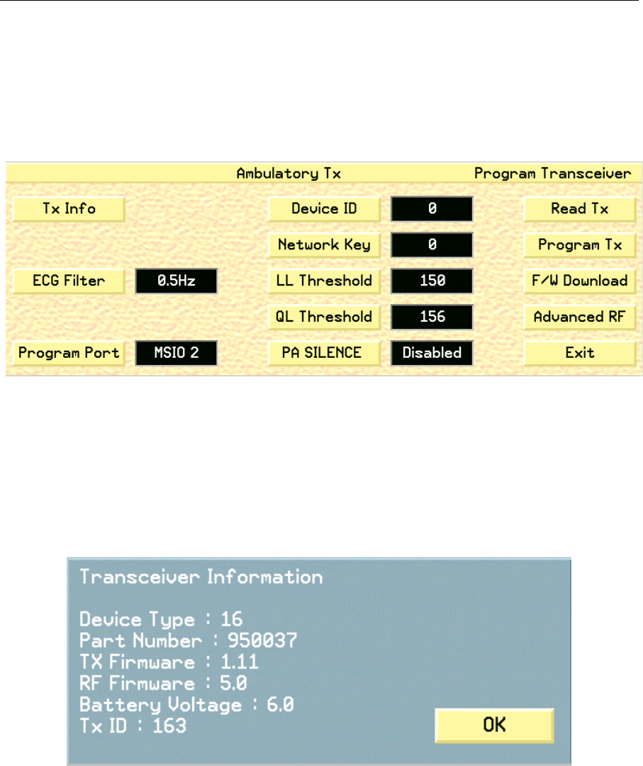
2. Click the Program AT button to open the Ambulatory Transceiver Program-
ming screen (fig. 77).
Fig. 77. Ambulatory Transceiver Programming screen
3. If the “No response from transceiver” popup appears, check the program-
ming cable connections and the transceiver battery. To re-attempt, wait until
the I/O LED on the DT-4500 stops flashing, and then select the Read TX but-
ton.
4. Click the Tx Info button to open the Transceiver Information popup (fig. 78),
which displays the current information for the attached transceiver. Click OK
to close the popup
Fig. 78. Transceiver Information popup
5. Click the Read TX button to read the currently programmed information
located on the transceiver and update the fields on the Program Transceiver
screen.

WMTS OPENNET LAN PROGRAMMING AND DIAGNOSTICS
124 PatientNet Administrator’s Guide, v1.04, 10001003-004, Revision B
All information contained herein is subject to the rights and restrictions on the title page.
6. Toggle ECG Filter (frequency response) to 0.5 or 0.05 MHz. This determines
how fast the ECG lead is adjusted after baseline changes.
WARNING: Program the DT-4500 transceiver to 0.05 Hz if you are performing ST analysis.
Otherwise, unpredictable and inaccurate analysis will result. You may use 0.5
Hz if you are not using ST analysis.
7. Click the Program Port button to select the MSIO port that will be used for
the transceiver programming interface. Clicking the button will cycle through
following options:
•MSIO 1
• MSIO 2 (DT-4500 default)
•MSIO 3
•MSIO 4
•None
Note: The Program Port field will only display the ports that are currently available
for the system. Thus, if all four ports are selected, and you decide to
change ports, none of the ports are available. You must select None on one
port in order to make it available (as the ports are mutually exclusive), and
then assign the available port to another device. Selecting None prevents
Port lockout.
8. Click the Device ID button to open a keypad that allows you to set the trans-
ceiver’s device identification number (0 - 1000).
9. Click the Network Key button to open a keypad that allows you to set the
transceiver’s network number (0 - 255).
WARNING: All transceivers must be programmed to the same Network Key as the Access
Points. This is an administrative procedure only. Do not attempt to program
the transceivers with the Network Key.
10. Click the LL Threshold button to open a keypad that allows you to set the
transceiver’s Loose Lead Threshold value (100-200). Electrode impedance
values below this threshold trigger a Lead Off alarm for all leads dependent
on the electrode violation. 150 is the default value.
11. Click the QL Threshold button to open a keypad that allows you to set the
transceiver’s Quality Lead Threshold value (100 - 200). This parameter
defines whether an electrode’s LED on the DT-4500 will illuminate when the
Attendant Present buttons are pressed. 156 is the default value.

WMTS OPENNET LAN PROGRAMMING AND DIAGNOSTICS
PatientNet Administrator’s Guide, v1.04, 10001003-004, Revision B 125
All information contained herein is subject to the rights and restrictions on the title page.
Transceiver Impedance Values
The DT-4500 Ambulatory Transceivers electrode impedance values, which are
displayed on the OpenNet Transceiver Status screen (see fig. 86 on page 136), indicate
the quality of the signal connection and are not the actual impedance values that are
measured by the system. The electrode impedance values range from 100 to 200 (opti-
mal). The typical values range between 180 and 200.
If the electrode’s impedance value is greater than the defined Quality Threshold value,
then its LED is illuminated. The DT-4500 stores the Quality Threshold value and uses
this value to determine whether or not the electrode LED should be illuminated when
the Attendant Present buttons are pressed. See the PatientNet Operator’s Manual for
details on the DT-4500 Buttons and LED indicators.
Note: A Lead Off alarm will occur when an electrode’s impedance value drops to,
or below, the current Loose Lead Threshold value.
12. Click the PA SILENCE button to enable or disable the Procedure Alarm
Silence function for the transceiver. See the PatientNet Operator’s Manual for
details on the Procedure Alarm Silence function.
13. Click the Program TX button to program a transceiver with the new parame-
ters and read the programmed information back for validation. The trans-
ceiver is now programmed.
Note: The attached device (AT or IT) is only programmed with the new parameters
when the Program TX button is pressed. Simply changing a parameter’s
value does not program the device. Programming is a two-step process:
(1) modify the desired parameter(s); (2) press the Program TX button.
Note: An error message that reads “Programming failure” is displayed when the
parameters read back from the transceiver differ from the parameters that
were written to the transceiver.
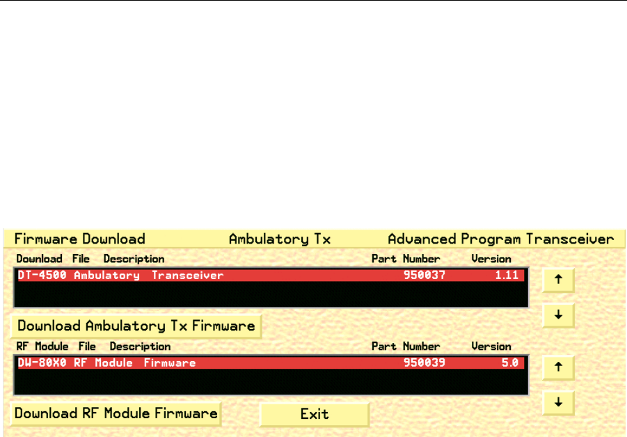
14. Click the F/W Download button to display the Advanced Program Trans-
ceiver Firmware Download screen (see fig. 79 on page 126).
15. Click the Advanced RF button to display the Advanced Program Transceiver
RF Module screen (see fig. 80 on page 127).
16. Click the Exit button to close the Ambulatory Transceiver Programming
screen and return to the OpenNet LAN screen.
WMTS OPENNET LAN PROGRAMMING AND DIAGNOSTICS
126 PatientNet Administrator’s Guide, v1.04, 10001003-004, Revision B
All information contained herein is subject to the rights and restrictions on the title page.
Downloading Ambulatory Transceiver (DT-4500) Firmware
You can download firmware modules for the DT-4500 and RF Module through the
Firmware Download Advanced Program Transceiver screen.
To download transceiver firmware:
1. Access the OpenNet LAN screen (page 101).
2. Access the Ambulatory Transceiver Program screen (page 123).
3. Click the F/W Download button to display the Advanced Program Trans-
ceiver Firmware Download screen (fig. 79).
Fig. 79. Firmware Download Advanced Program Transceiver Screen, AT
Note: If no Firmware Download Modules appear in the blackboard, then call your
technical support representative to order the appropriate Download Firm-
ware Module Disk.
4. Use the up and down arrows to view the available transceiver firmware down-
load modules in the Download File Description field. Select the appropriate
download module for the transceiver type.
5. Click the Download Ambulatory Tx Firmware button to download the DT-
4500 firmware. The DT-4500 battery voltage is checked and verified prior to
downloading.
• If the voltage check fails, then the transceiver programming is aborted.
• If ample voltage is available, then the DT-4500 is powered off and the down-
loading popup appears. Click Continue to proceed with downloading the
new firmware. Click Cancel to abort the download and the transceiver’s
firmware is not modified.
6. Click the Download RF Module Firmware button to download the RF Mod-
ule’s firmware. Click Continue or Cancel when the downloading popup
appears.
• Select Continue to proceed with downloading the new RF Module
firmware.
•Click Cancel to abort the download and the firmware is not modified.
7. Click the Exit button to return to the Ambulatory Transceiver Programming
screen.
WMTS OPENNET LAN PROGRAMMING AND DIAGNOSTICS
PatientNet Administrator’s Guide, v1.04, 10001003-004, Revision B 127
All information contained herein is subject to the rights and restrictions on the title page.
Programming RF Modules for Ambulatory Transceivers
You can program the RF Modules of Ambulatory Transceivers (AT), DT-4500s, with
the RF Module Advanced Program Transceiver screen.
To program AT RF Modules:
1. Access the OpenNet LAN screen (page 101).
2. Access the Ambulatory Transceiver Program screen (page 123).
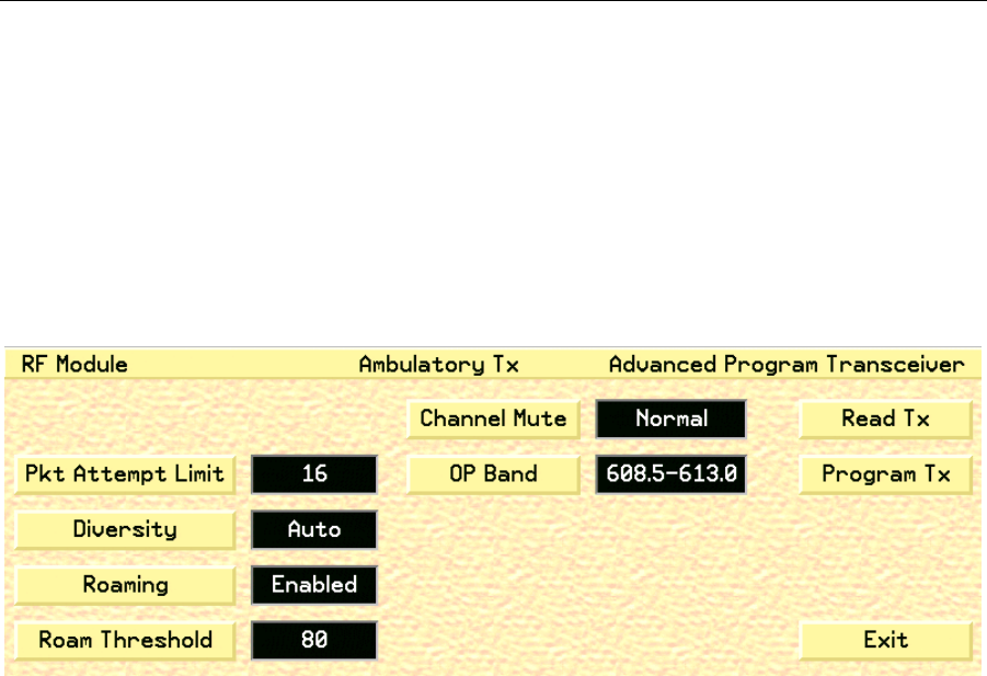
3. Click the Advanced RF button to display the RF Module Advanced Program
Transceiver screen (fig. 80).
Fig. 80. RF Module Advanced Programming screen, AT
4. Click the Read TX button to read the currently programmed information
located on the transceiver and update the fields.
5. Click the Pkt Attempt Limit button to open a keypad that allows you to set
the number of packet attempts limit for the selected RF module. The available
settings are between 0 and 22.
6. Click the Diversity button to toggle between Ant A, Ant B, or Auto, which
sets the transceiver’s diversity setting.
7. Click the Roaming button to toggle between Enabled and Disabled, which
sets the transceiver’s roaming capabilities.
8. Click the Roam Threshold button to open a keypad that allows you to enter
the transceiver’s roam threshold value. The available settings are between 0
and 255.
9. Click the Channel Mute button to set the transceiver’s Channel Mute fre-
quency. 32 frequencies are available based on the RF Modules hardware.

WMTS OPENNET LAN PROGRAMMING AND DIAGNOSTICS
128 PatientNet Administrator’s Guide, v1.04, 10001003-004, Revision B
All information contained herein is subject to the rights and restrictions on the title page.
10. Click the OP Band button to set the operating band that will be used by the
RF Module.
• Typically, the 608.5-613.0 OP Band is selected. However, where the Patient-
Net System operates in the same hospital as another system (or systems) that
also use(s) the 608-614 MHz WMTS band, it will be necessary to select one
of the sub-bands. The sub-band should coordinate with the hospital’s spec-
trum policy.
• Additional sub-bands include: 608.5-609.7, 609.6-610.8, 610.7-611.9, and
611.8-613.0
WARNING: All transceivers must be programmed to the same OP Band as the Access
Points. This is an administrative procedure only. Do not attempt to program
the transceivers with the selected OP Band.
11. Click the Program TX button to program a transceiver and read the pro-
grammed information back for validation. The transceiver is now pro-
grammed.
12. Click the Exit button to return to the Ambulatory Transceiver Programming
screen.