Data Sciences PTDM1 Digital Animal Implant Transceiver for use in Medical Research Laboratory Environments User Manual
Data Sciences International Inc Digital Animal Implant Transceiver for use in Medical Research Laboratory Environments Users Manual
Contents
- 1. Users Manual
- 2. Users Manual Warning Statement
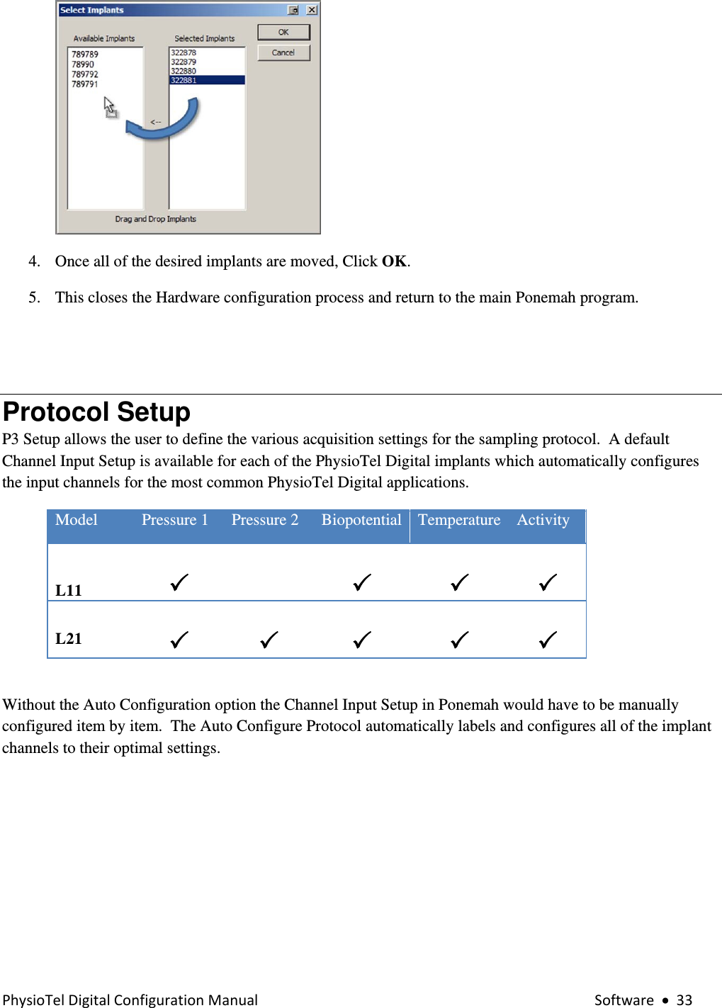
Users Manual

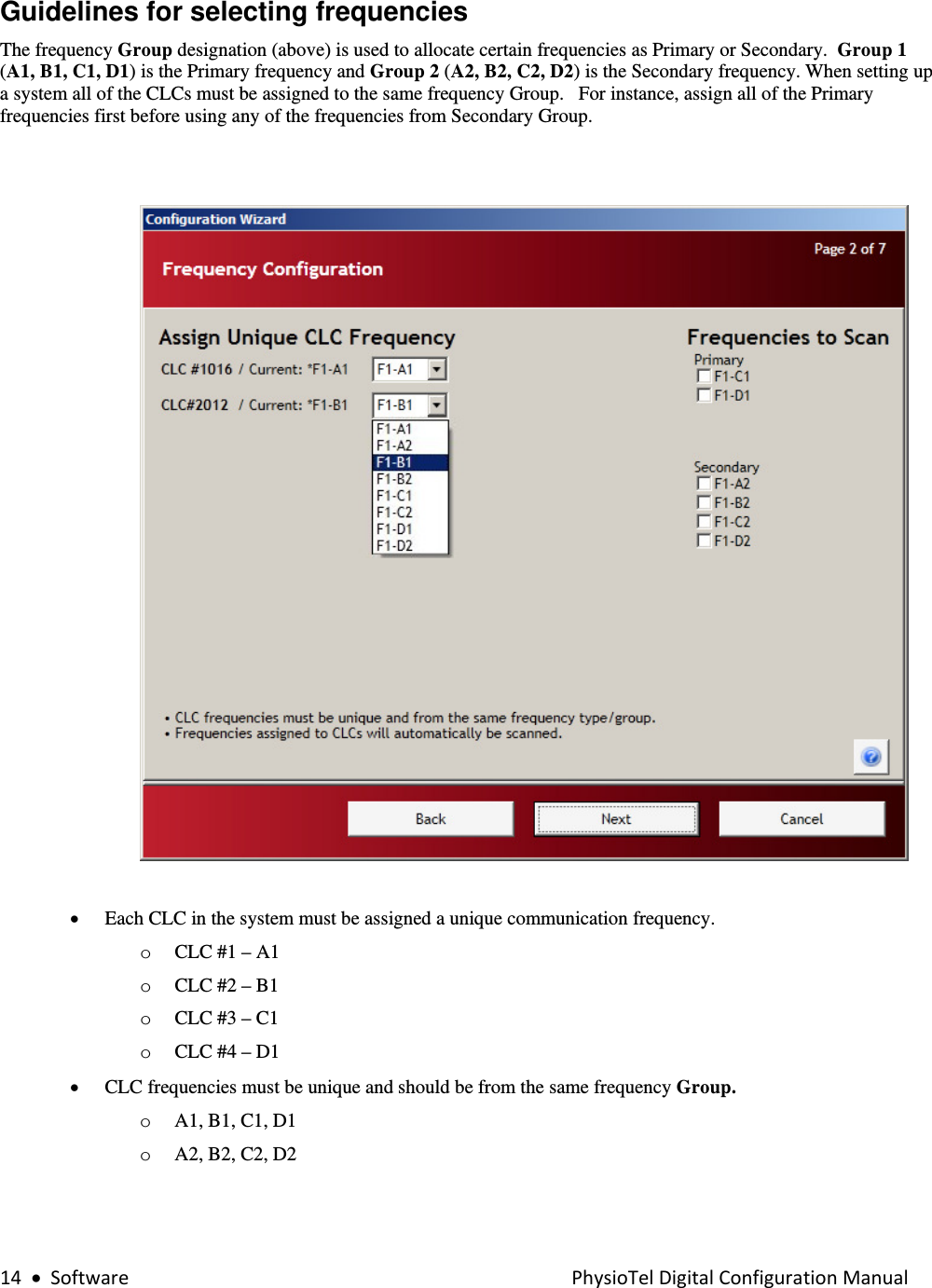
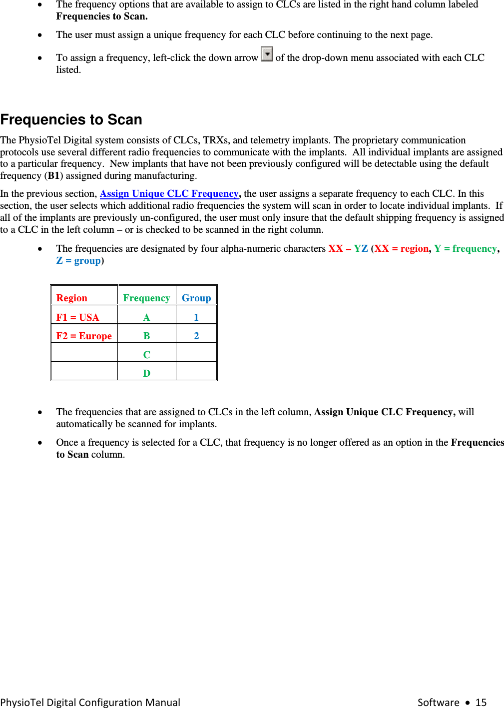
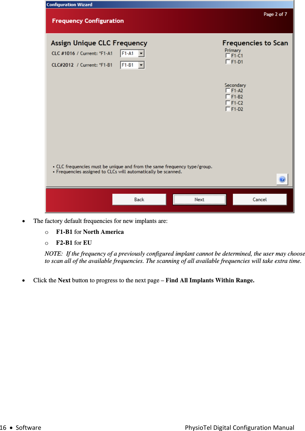
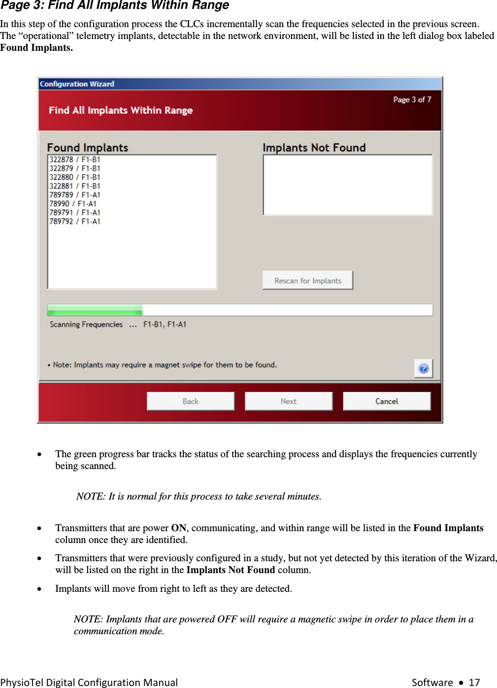
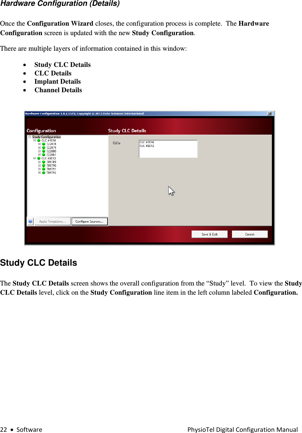
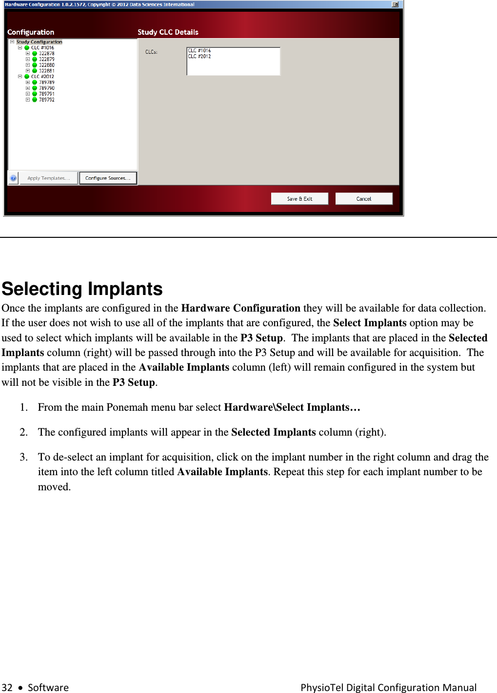
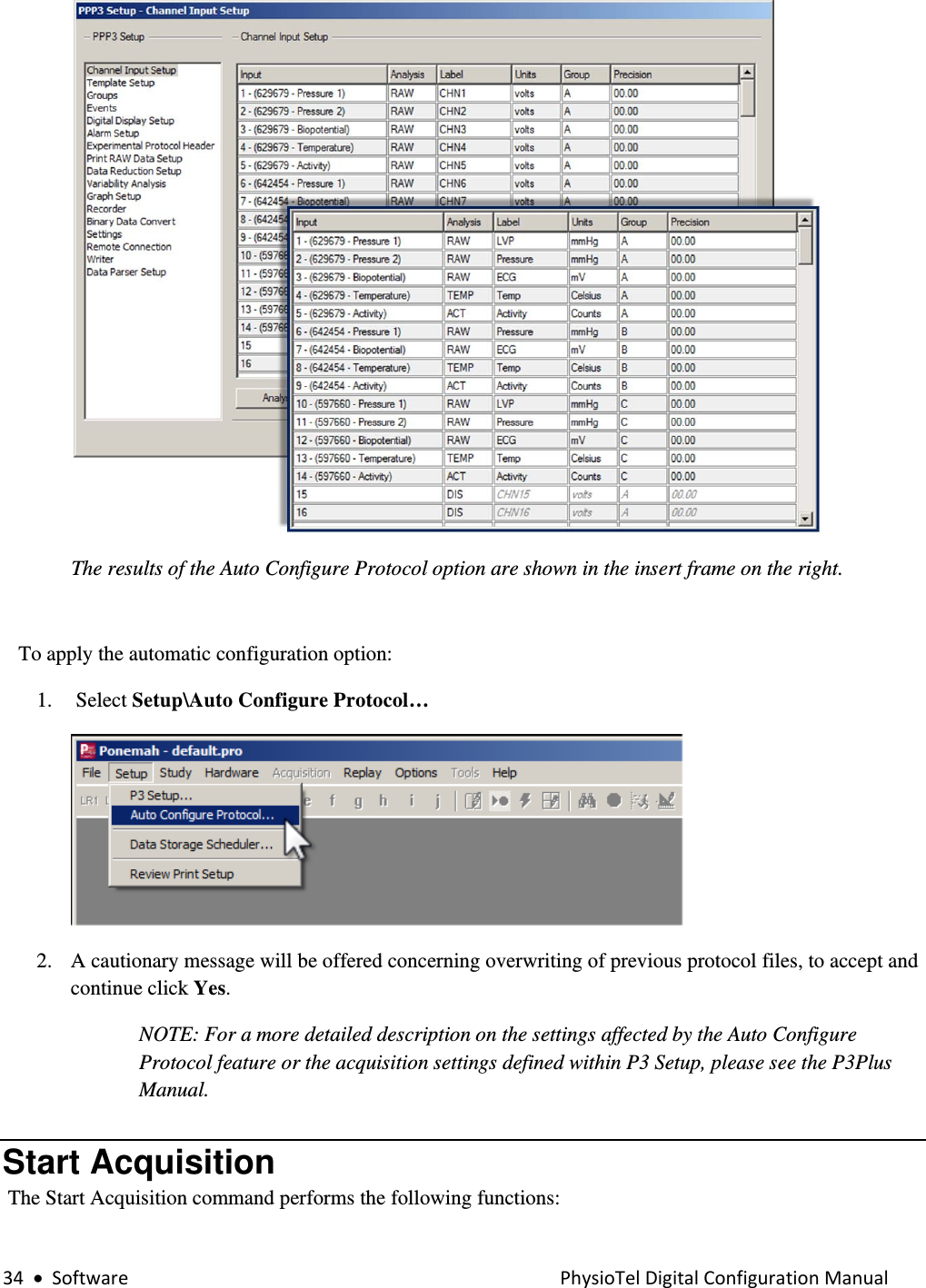
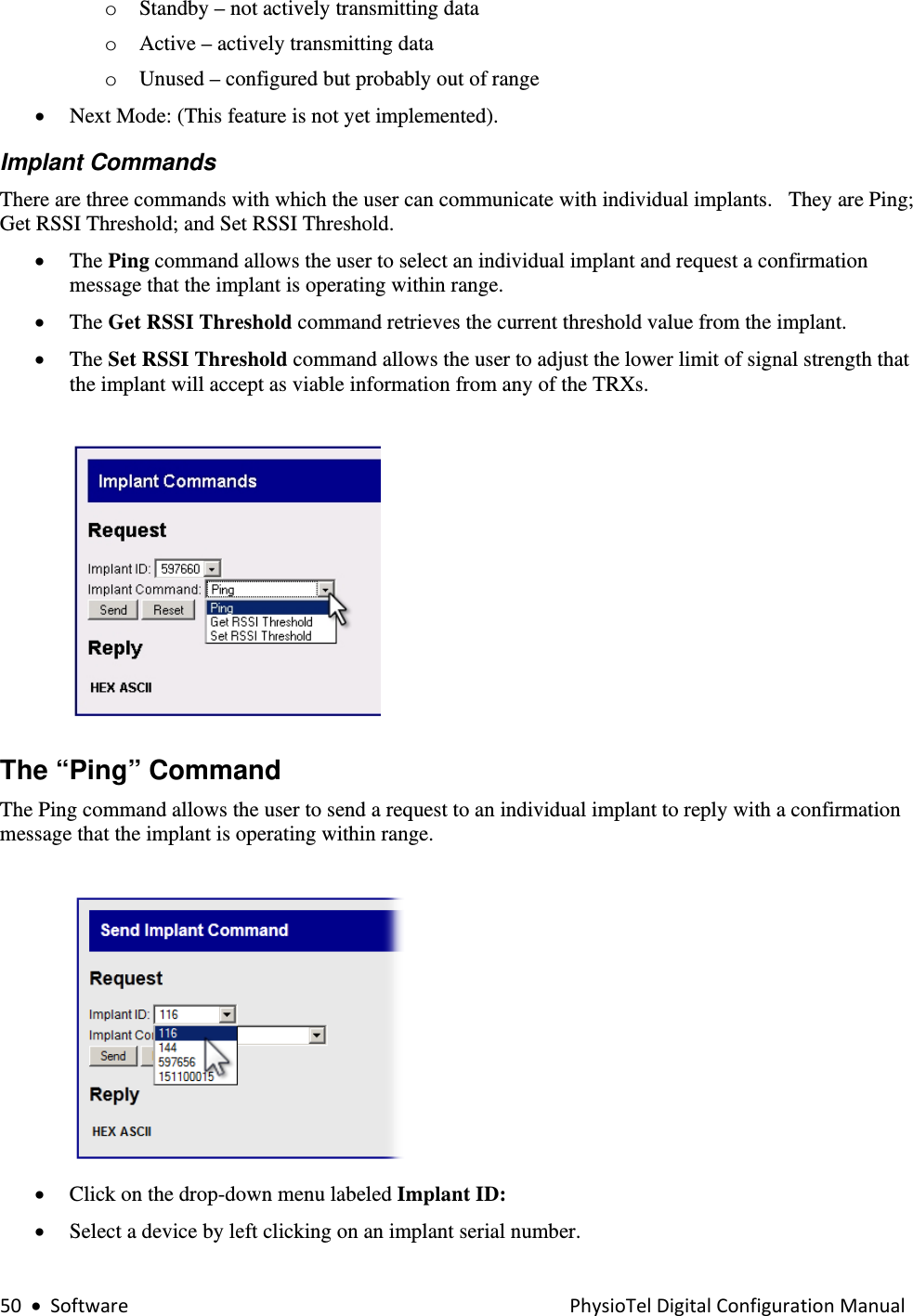
![PhysioTelDigitalConfigurationManual Software•23 • The Configuration column lists the entire configuration in an expandable tree structure. • The CLCs are listed with the assigned transmitters listed underneath. • Click on the Study Configuration line item in the left column labeled Configuration. • The right hand column Study CLC Details, lists the CLCs in the new configuration. • Hover the mouse cursor over any line item in the Configuration box to activate an information pop-up with that device’s key status condition. • The tree structure can be expanded and contracted by clicking on the [+] and [-] icons to the left of the individual line items.](https://usermanual.wiki/Data-Sciences/PTDM1.Users-Manual/User-Guide-2359491-Page-23.png)

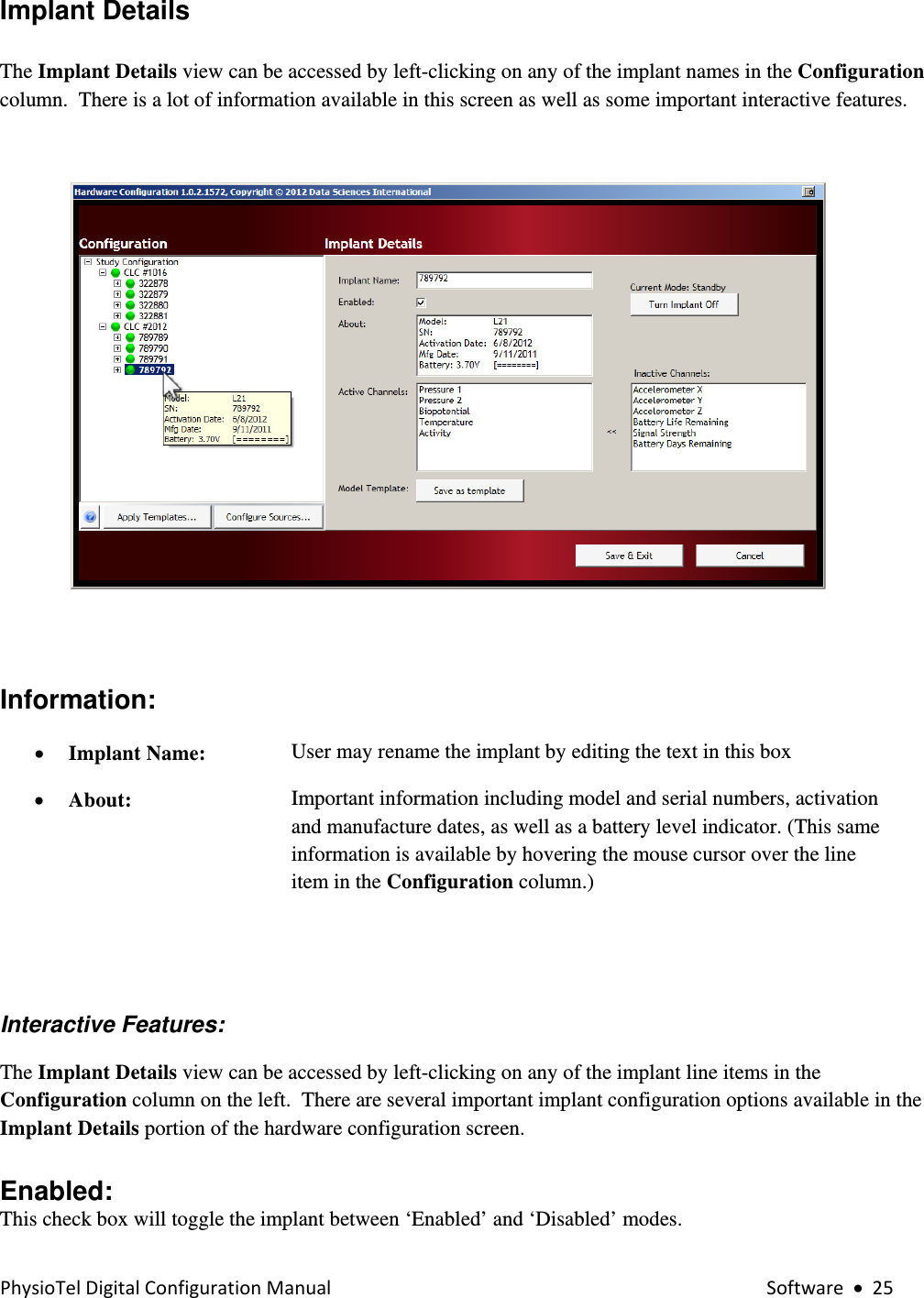
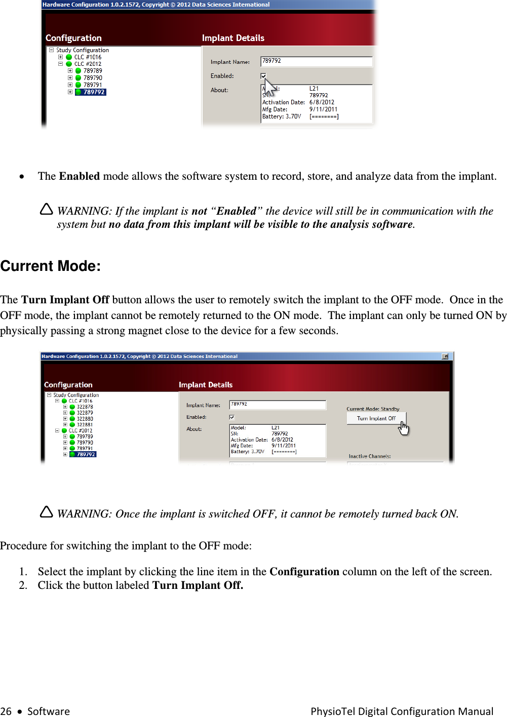
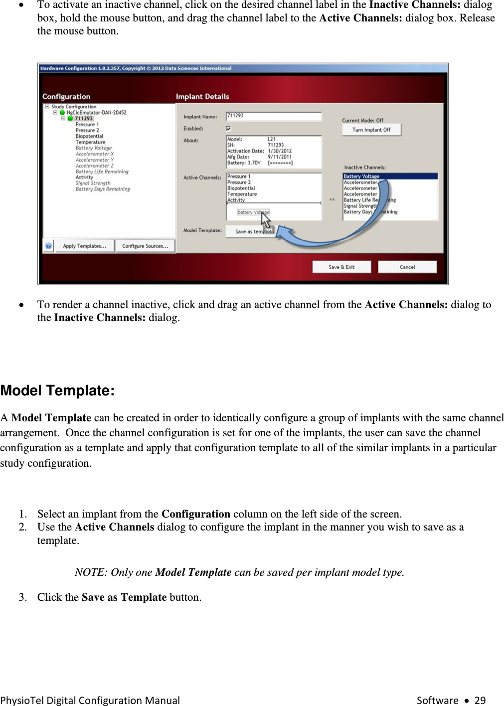
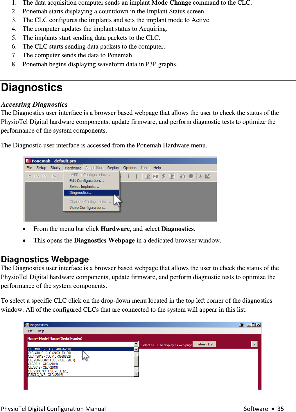
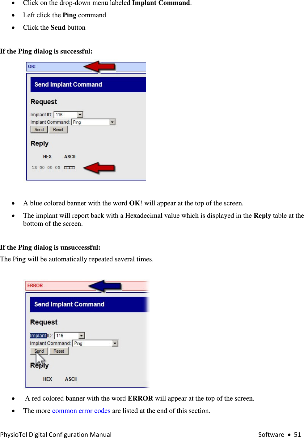
![28•SoftwarePhysioTelDigitalConfigurationManualActive Channels: The Active Channels dialog allows the user to select which data collection channels are activated in the implant. Active implant channels collect physiologic data and transmit the data through the acquisition system to be stored in the data acquisition computer. Inactive channels do not collect physiologic data, those particular implant functions are turned off. In addition to avoiding the collection of unnecessary data, the in-activation of certain data channels has the potential to preserve battery resources. Channel Details • Locate an implant by expanding the Study Configuration tree structure in the Configuration dialog box. The tree structure can be expanded and contracted by clicking on the [+] and [-] icons to the left of the individual line items. • Click on the [+] icon to the left of implant name in the Configuration dialog box to view the implant details. • The current “active” channels are listed in bold type in the Configuration box once the tree structure is fully expanded. The inactive channels are listed in italic text. Activating Inactive Channels • The default channels for the particular implant type are automatically listed in the Active Channels dialog box in the center of the Implant Details screen.](https://usermanual.wiki/Data-Sciences/PTDM1.Users-Manual/User-Guide-2359491-Page-28.png)