Data Sciences PTDM1 Digital Animal Implant Transceiver for use in Medical Research Laboratory Environments User Manual
Data Sciences International Inc Digital Animal Implant Transceiver for use in Medical Research Laboratory Environments Users Manual
Contents
- 1. Users Manual
- 2. Users Manual Warning Statement
Users Manual
DSI
PhysioTel Digital Telemetry
Platform
Model: PhysioTel Digital
Manual: MU00285
Revision: 1
Data Sciences International
119 14th Street NW, Suite 100
St. Paul, MN 55112
Phone: +1 (651) 481-7400
US: +1 (800) 262-9687
Email: support@datasci.com
www.datasci.com

PhysioTelDigitalConfigurationManualContents•iii
Copyright© 1997-2012 Data Sciences International. All rights reserved. No part of this manual may be
reproduced, translated, transcribed, or transmitted in any form or by any means manual, electronic,
electromagnetic, chemical, or optical without the written permission of Data Sciences International.
iv•ContentsPhysioTelDigitalConfigurationManual
Contents
PhysioTelDigitalTelemetryPlatform...........................................................................................................5
TheoryofOperation......................................................................................................................................5
System Diagram......................................................................................................................... 6
Software........................................................................................................................................................6
Getting Started ........................................................................................................................... 6
Hardware Selection ..................................................................................................... 6
Hardware Configuration ............................................................................................................ 7
Accessing Hardware Configuration through Ponemah................................................ 8
Configuration Wizard .................................................................................................. 8
Study CLC Details ..................................................................................................... 22
CLC Details ............................................................................................................... 24
Implant Details .......................................................................................................... 25
Channel Details ......................................................................................................... 28
Selecting Implants ................................................................................................................... 32
Protocol Setup .......................................................................................................................... 33
Start Acquisition ...................................................................................................................... 34
Diagnostics .............................................................................................................................. 35
Diagnostics Webpage ................................................................................................ 35
Glossary.......................................................................................................................................................56
Appendices..................................................................................................................................................57
Appendix A: Hexadecimal Conversion ................................................................................... 59
PhysioTelDigitalConfigurationManualPhysioTelDigitalTelemetryPlatform•5
PhysioTel Digital Telemetry
Platform
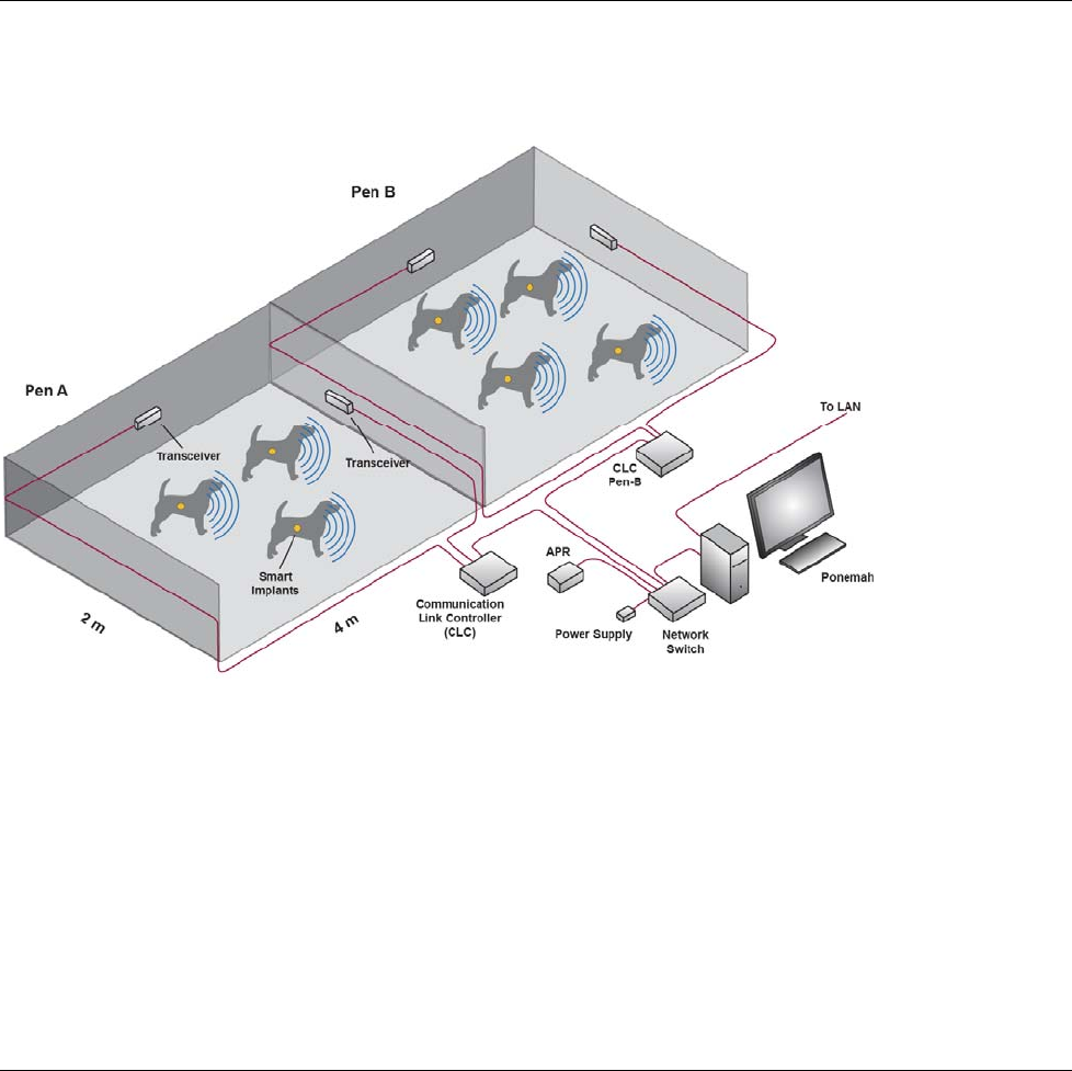
Theory of Operation
There are four main components of the PhysioTel Digital telemetry system; the data acquisition
computer, the Communication Link Controller (CLC), the transceivers (TRX), and the smart implants.
The CLC and the implants are the components that are actively communicating with one another; the
TRX is the transmitting\receiving link between them. Using a hardware configuration wizard in the data
acquisition software, the user chooses a set of implants and assigns them to a particular CLC; up to four
implants can be assigned to one CLC. Each CLC operates on a separate communication frequency.
During the configuration process the CLC instructs the implants to “Join” its unique frequency. Once
joined, the implants are ready to collect physiologic data and transmit it back to the data acquisition
computer.
6•SoftwarePhysioTelDigitalConfigurationManual
System Diagram
Software
Getting Started
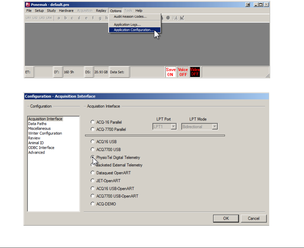
Hardware Selection
The PhysioTel Digital Telemetry system is a specific Application Interface within the Ponemah software.
Select the Application Configuration function from the Options menu. Select PhysioTel Digital Telemetry
and click OK.
PhysioTelDigitalConfigurationManual Software•7
Hardware Configuration
The PhysioTel Digital system automates the collection of physiologic data from freely moving research animals via
wireless telemetry. The system consists of a sophisticated acquisition and analysis software platform and a family of
advanced, state of the art implantable telemetry transmitters. The communications link between these two components
consists of wired and wireless components collectively referred to as the PhysioTel Digital Hardware.
8•SoftwarePhysioTelDigitalConfigurationManual
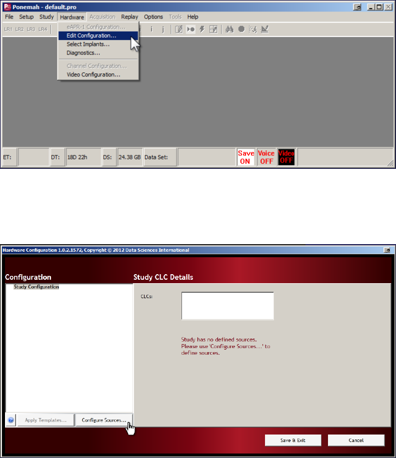
Accessing Hardware Configuration through Ponemah
• From the menu bar click Hardware, and select Edit Configuration…
• This opens the Hardware Configuration window.
• If this is a new configuration, the red colored message text will inform you that you need to use Configure
Sources… to define telemetry implant sources.
• Click on the Configure Sources… button to open the Configuration Wizard and begin the study
configuration process.
Configuration Wizard
PhysioTelDigitalConfigurationManual Software•9
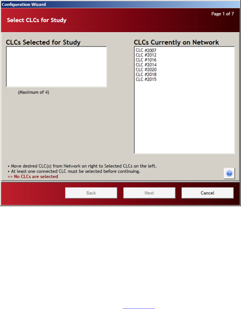
Page 1: Select CLCs for Study
Page 1 of the Configuration Wizard is basic inventory. The wizard queries the network; it finds all of the active CLCs
(Communication Link Controller) on the system and lists them in the right hand column titled CLCs Currently on
Network. To configure a CLC for use in the system, select a CLC and move it from the right column, CLCs Currently
on Network to the left column, CLCs Selected for Study.
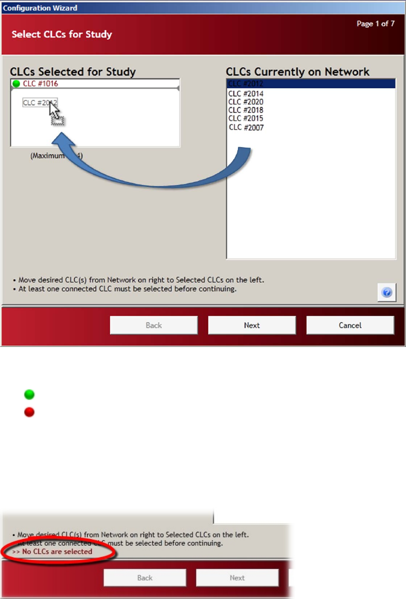
• Select a CLC in the right column, click and hold the selection with the left mouse button and drag the
selection to the left column. Release the mouse button and the CLC will be added to the list.
NOTE: The Configuration Wizard will only a maximum of four CLCs to be configured during each run
of the configuration process (4 CLCs for frequency F1, 3 CLCs for F2). If more than four CLCs are to
be configured, the Configuration Wizard will have to be run again.
10•SoftwarePhysioTelDigitalConfigurationManual
• The newly added CLC will be added to the list with a circular status indicator.
Green colored indicator: CLC enabled
Red colored indicator : CLC disabled
• If the colored status indicator does not change from red to green, an error message will be displayed in the
lower left corner of the screen indicating the nature of the discrepancy
• An error message may also appear even though the indicator is green.
• At least one CLC must be selected and enabled (green indicator) before continuing.
PhysioTelDigitalConfigurationManual Software•11
• All of the “Selected” CLCs (left column) must be enabled (green indicator) before continuing. Enabled
status means that the CLC is “powered up” and not in use by another system.
• If everything is in order, you will be able to click the Next button to proceed to Page 2.
• If the Next button is not available, consult the error messages mentioned above.
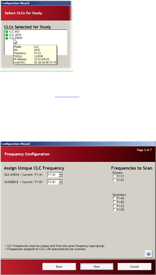
NOTE: At any time a CLC information pop up is available by hovering your mouse cursor over any of
the CLC labels on the page. Details concerning the content of this information pop-up can be found in
the chapter titled “CLC Details”
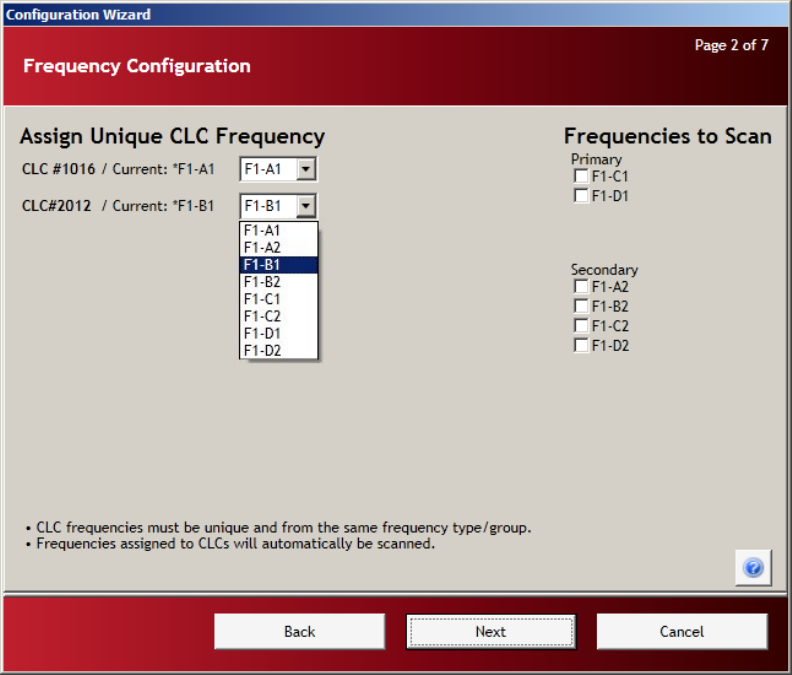
Page 2: Frequency Configuration
Page 2 allows the user to select a separate frequency for each CLC. As many as four CLCs may be configured at one
time, but each CLC must be assigned a unique operating frequency.
12•SoftwarePhysioTelDigitalConfigurationManual
Assign Unique CLC Frequency
Frequencies to Scan
Assign Unique CLC Frequency
• The CLCs that are enabled in the previous step are listed in the left hand column labeled Assign Unique
CLC Frequency.
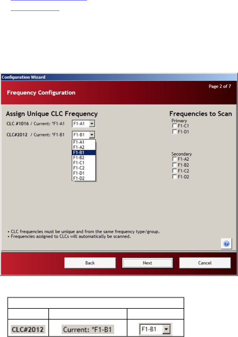
• The left hand side of the page is arranged in a table.
Assign Unique CLC Frequency
CLC label Current CLC frequency Select frequency
o CLC Label: The name that is assigned to the CLC
o Current CLC frequency: The currently assigned frequency

PhysioTelDigitalConfigurationManual Software•13
o Select frequency: Drop-down with frequency options
• The current operating frequency of each CLC is listed in the center column.
• Use the drop-down menu to the right of the CLC to select an available communication frequency.
• The frequencies are designated by four alpha-numeric characters XX – YZ (XX = region, Y = frequency,
Z = group).
Region Frequency Group
F1 = USA A 1
F2 = Europe B 2
C
D
• The available frequencies are as listed below:
USA Europe
F1-A1 F2-A1
F1-B1 F2-B1
F1-C1 F2-C1
F1-D1
F1-A2 F2-A2
F1-B2 F2-B2
F1-C2
F1-D2
14•SoftwarePhysioTelDigitalConfigurationManual
Guidelines for selecting frequencies
The frequency Group designation (above) is used to allocate certain frequencies as Primary or Secondary. Group 1
(A1, B1, C1, D1) is the Primary frequency and Group 2 (A2, B2, C2, D2) is the Secondary frequency. When setting up
a system all of the CLCs must be assigned to the same frequency Group. For instance, assign all of the Primary
frequencies first before using any of the frequencies from Secondary Group.
• Each CLC in the system must be assigned a unique communication frequency.
o CLC #1 – A1
o CLC #2 – B1
o CLC #3 – C1
o CLC #4 – D1
• CLC frequencies must be unique and should be from the same frequency Group.
o A1, B1, C1, D1
o A2, B2, C2, D2

PhysioTelDigitalConfigurationManual Software•15
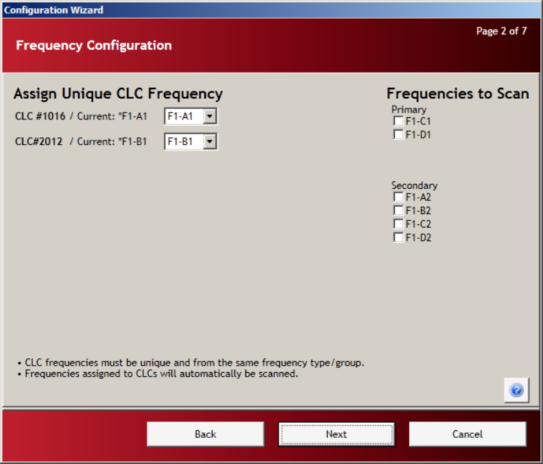
• The frequency options that are available to assign to CLCs are listed in the right hand column labeled
Frequencies to Scan.
• The user must assign a unique frequency for each CLC before continuing to the next page.
• To assign a frequency, left-click the down arrow of the drop-down menu associated with each CLC
listed.
Frequencies to Scan
The PhysioTel Digital system consists of CLCs, TRXs, and telemetry implants. The proprietary communication
protocols use several different radio frequencies to communicate with the implants. All individual implants are assigned
to a particular frequency. New implants that have not been previously configured will be detectable using the default
frequency (B1) assigned during manufacturing.
In the previous section, Assign Unique CLC Frequency, the user assigns a separate frequency to each CLC. In this
section, the user selects which additional radio frequencies the system will scan in order to locate individual implants. If
all of the implants are previously un-configured, the user must only insure that the default shipping frequency is assigned
to a CLC in the left column – or is checked to be scanned in the right column.
• The frequencies are designated by four alpha-numeric characters XX – YZ (XX = region, Y = frequency,
Z = group)
Region Frequency Group
F1 = USA A 1
F2 = Europe B 2
C
D
• The frequencies that are assigned to CLCs in the left column, Assign Unique CLC Frequency, will
automatically be scanned for implants.
• Once a frequency is selected for a CLC, that frequency is no longer offered as an option in the Frequencies
to Scan column.
16•SoftwarePhysioTelDigitalConfigurationManual
• The factory default frequencies for new implants are:
o F1-B1 for North America
o F2-B1 for EU
NOTE: If the frequency of a previously configured implant cannot be determined, the user may choose
to scan all of the available frequencies. The scanning of all available frequencies will take extra time.
• Click the Next button to progress to the next page – Find All Implants Within Range.
PhysioTelDigitalConfigurationManual Software•17
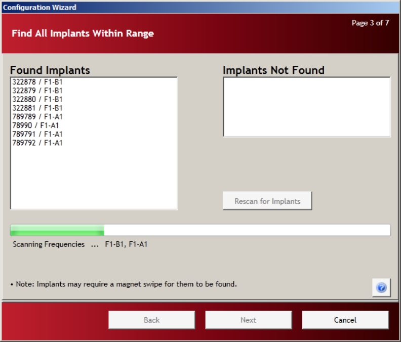
Page 3: Find All Implants Within Range
In this step of the configuration process the CLCs incrementally scan the frequencies selected in the previous screen.
The “operational” telemetry implants, detectable in the network environment, will be listed in the left dialog box labeled
Found Implants.
• The green progress bar tracks the status of the searching process and displays the frequencies currently
being scanned.
NOTE: It is normal for this process to take several minutes.
• Transmitters that are power ON, communicating, and within range will be listed in the Found Implants
column once they are identified.
• Transmitters that were previously configured in a study, but not yet detected by this iteration of the Wizard,
will be listed on the right in the Implants Not Found column.
• Implants will move from right to left as they are detected.
NOTE: Implants that are powered OFF will require a magnetic swipe in order to place them in a
communication mode.
18•SoftwarePhysioTelDigitalConfigurationManual
• The Configuration Wizard can detect a maximum of eight implants per cycle, if the system will ultimately
have more than eight implants; it is a good idea to power up and configure implants in groups of less than
eight devices.
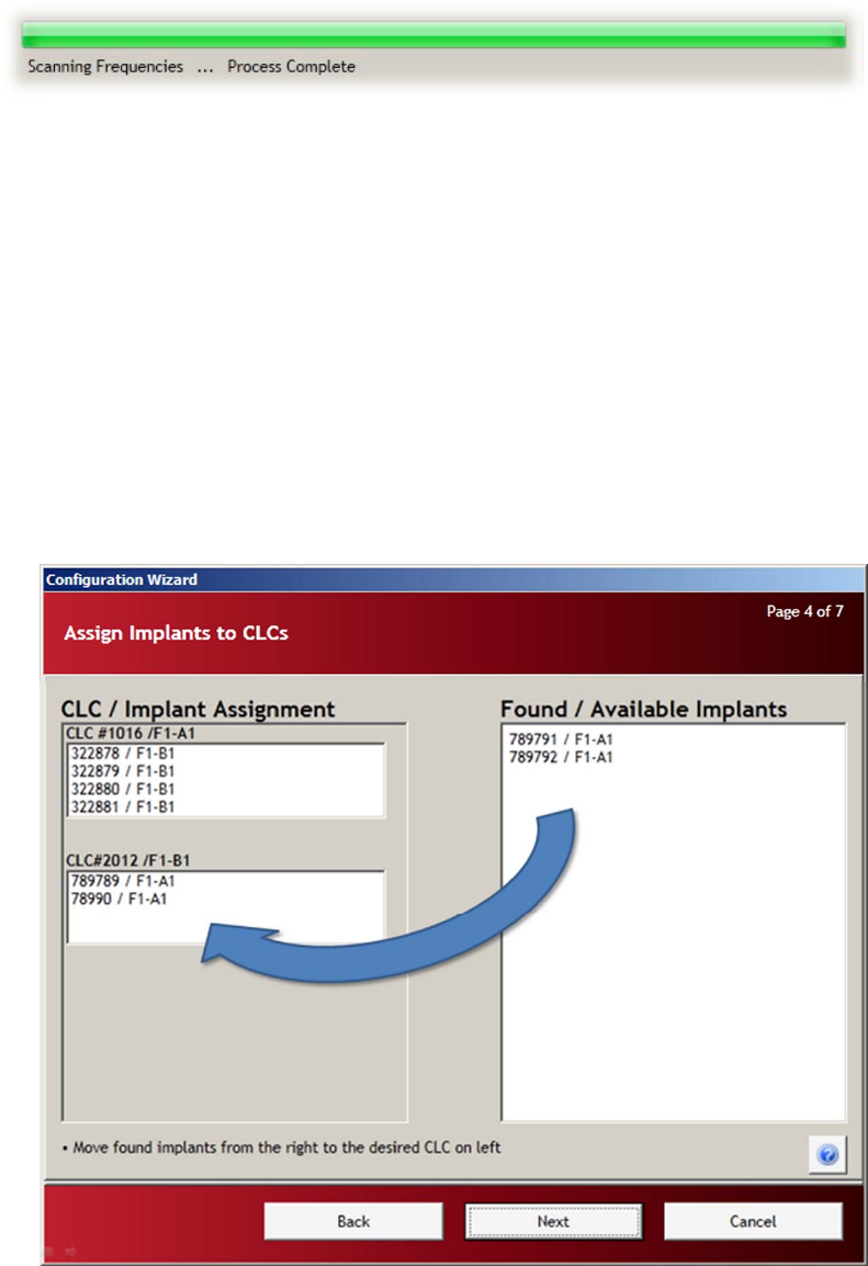
• Once the scanning process is complete and all of the implants are identified, the progress bar will be solid
green and the message “Scanning Frequencies … Process Complete” will appear below the progress bar.
• Click NEXT to proceed to the next step – Assign Implants to CLCs.
Page 4: Assign Implants to CLCs
This stage of the process allows the user to custom configure the system to assign individual implants to specific CLCs:
e.g. “I would like implant A to be assigned to CLC #4, communicating on frequency F1-A1.”
• The implants that have previously been assigned to CLCs will automatically be shown in the left column
labeled CLC / Implant Assignment.
• The implants that have not been previously assigned to a CLC will appear in the right column labeled
Found / Available Implants.
• To assign an available implant, click on the implant name in the right column and drag the implant into the
box below the desired CLC on the left.
• Once all of the implants are assigned to the appropriate CLCs, Click Next.
PhysioTelDigitalConfigurationManual Software•19
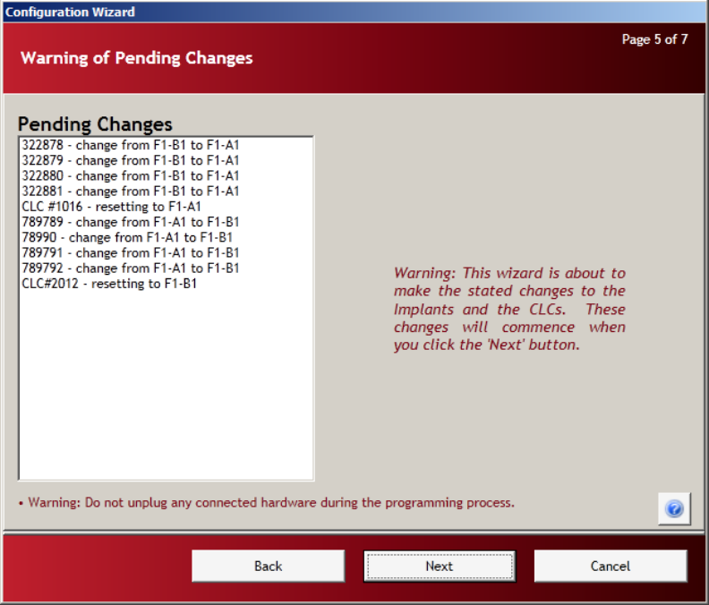
Page 5: Warning of Pending Changes
Page 5 is a confirmation page that warns the user that the pending changes are about to be committed. The
Pending Changes are listed in the dialog box on the left. There is no user interaction in this step of the
Wizard, it merely warns the user that once the Next button is pressed, there is no “Undo” option.
Ì WARNING: Do not unplug any connected hardware during the programming process.
Click Next to progress to Page 6: Change Implant Frequencies.
20•SoftwarePhysioTelDigitalConfigurationManual
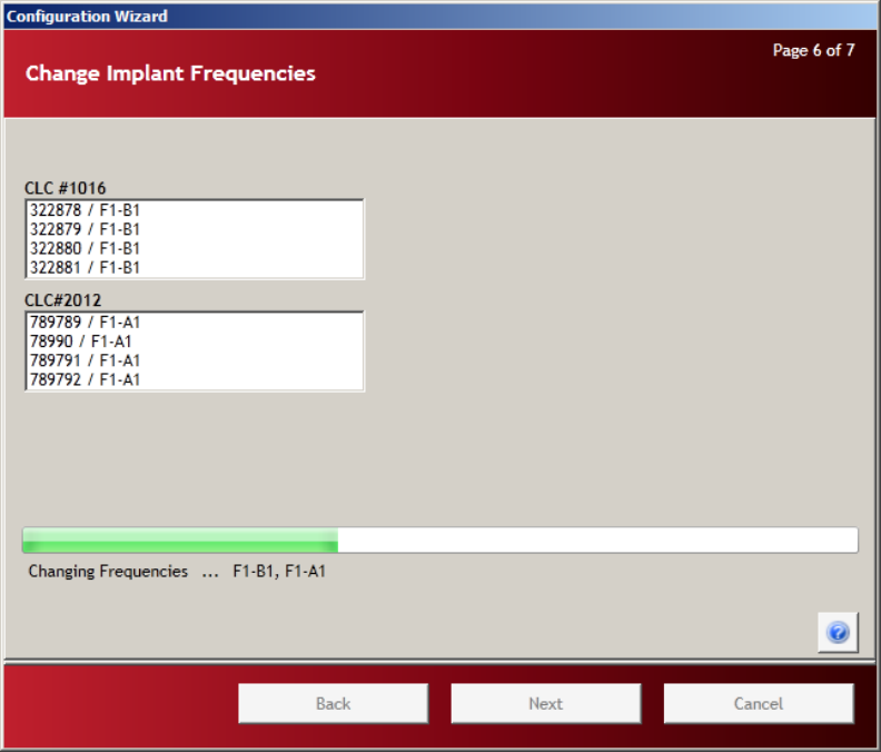
Page 6: Change Implant Frequencies
Page six is the re-assignment process. One by one, the CLCs instruct the implants to switch frequencies and
the implants comply. Once an implant switches to a new frequency, it can no longer communicate with its
previously assigned CLC. The implant must then wait until a CLC on its new frequency attempts to contact
it.
• The green progress bar shows the status of the re-assignment process and displays the pertinent
information.
NOTE: This process may take several minutes.
• As the re-assignments progress, the information in the text box below the CLC listing will
continuously update.
• Do not alter any components of the system until confirmation that the process is complete.
• Completion of the process is indicated by a completely green progress bar with the message
“Process Complete” below.
• Click Next to progress to Page 7: Accept Configuration.
PhysioTelDigitalConfigurationManual Software•21
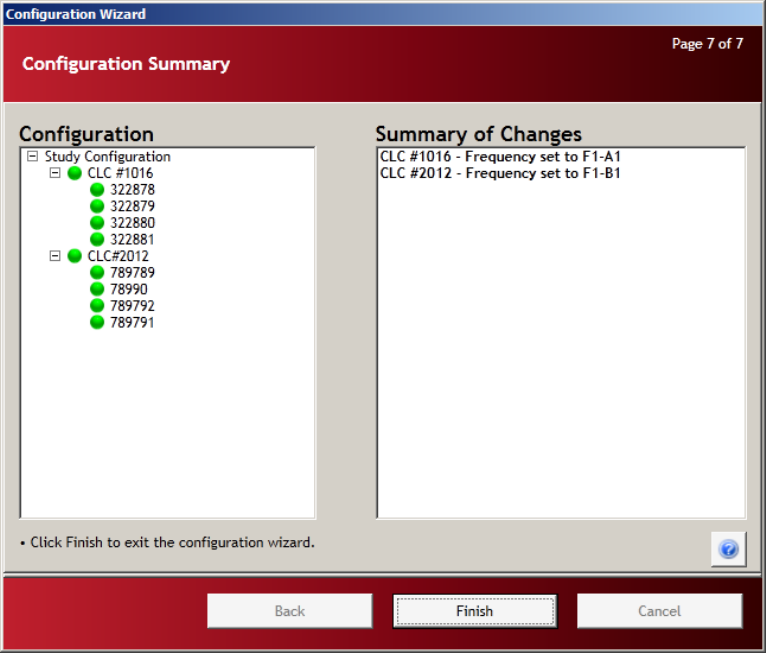
Page 7: Accept Configuration
Page seven is the final step in the Configuration Wizard. The column on the left, Configuration, presents
the newly configured tree structure of CLCs and implants. The column on the right, Summary of Changes,
will indicate successes and failures in the configuration process. If the user wishes to alter or repair the final
configuration listed in the Configuration dialog box, the wizard will have to be run again.
• The Configuration column on the left outlines the new hardware configuration.
o Study Configuration
CLC 1
• Implant 1
• Implant 2
• Etc…
CLC 2
• Implant 1
• Implant 2
• Etc…
• To accept and save the study configuration as it is outlined in the Configuration dialog box, click the
Finish button.
22•SoftwarePhysioTelDigitalConfigurationManual
Hardware Configuration (Details)
Once the Configuration Wizard closes, the configuration process is complete. The Hardware
Configuration screen is updated with the new Study Configuration.
There are multiple layers of information contained in this window:
• Study CLC Details
• CLC Details
• Implant Details
• Channel Details
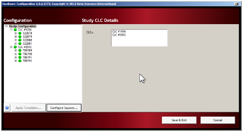
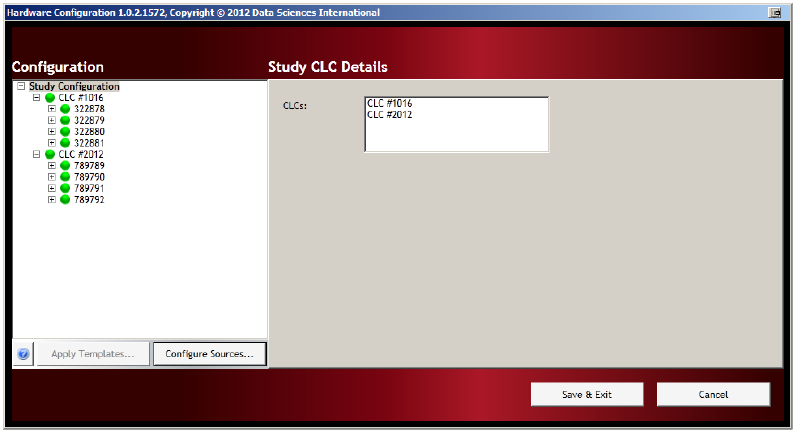
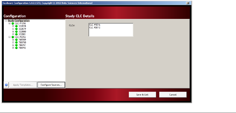
Study CLC Details
The Study CLC Details screen shows the overall configuration from the “Study” level. To view the Study
CLC Details level, click on the Study Configuration line item in the left column labeled Configuration.
PhysioTelDigitalConfigurationManual Software•23
• The Configuration column lists the entire configuration in an expandable tree structure.
• The CLCs are listed with the assigned transmitters listed underneath.
• Click on the Study Configuration line item in the left column labeled Configuration.
• The right hand column Study CLC Details, lists the CLCs in the new configuration.
• Hover the mouse cursor over any line item in the Configuration box to activate an information pop-
up with that device’s key status condition.
• The tree structure can be expanded and contracted by clicking on the [+] and [-] icons to the left of
the individual line items.
24•SoftwarePhysioTelDigitalConfigurationManual
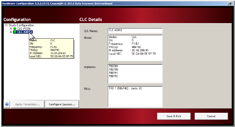
CLC Details
The CLC Details view can be accessed by left-clicking on any of the CLC line items in the Configuration
column on the left.
CLC Details include:
• CLC Name: User may rename the CLC by editing the text in this box
• About: Model
Serial number
Frequency
TRX(s)
IP Address
Local NIC (Network Interface Card)
• Implants: List of the implant names assigned to that CLC
• TRXs: List of TRXs and serial numbers assigned to that CLC –
the “Jack” number on the back panel of the CLC that the
TRX is plugged into
PhysioTelDigitalConfigurationManual Software•25
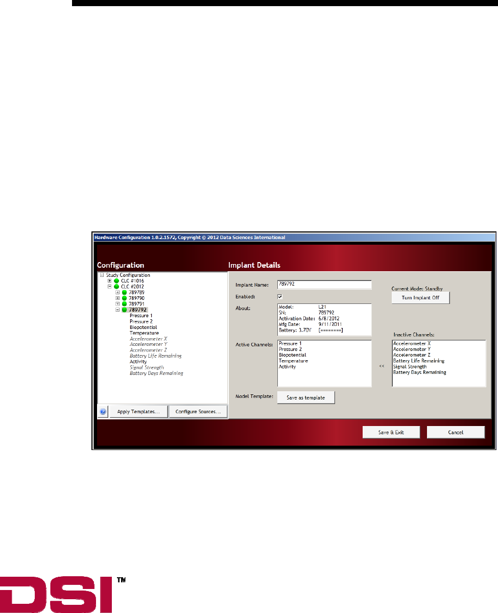
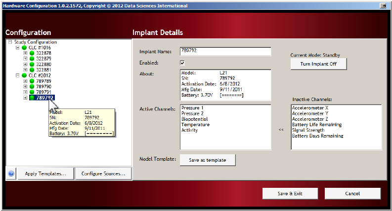
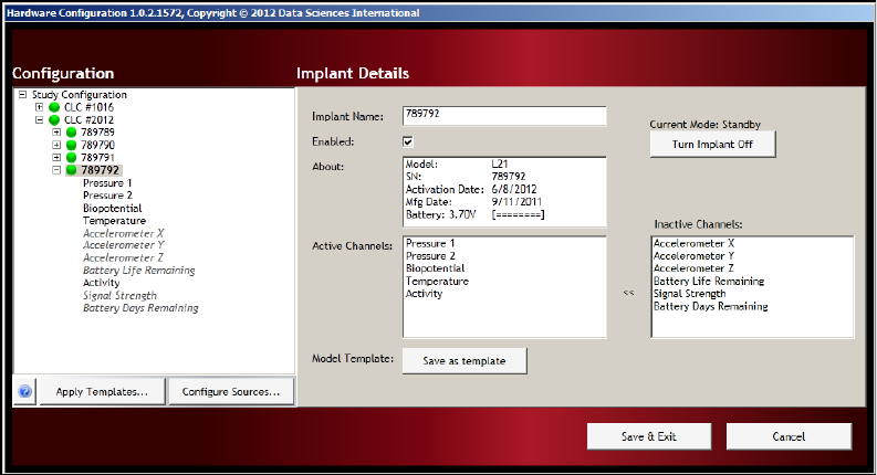
Implant Details
The Implant Details view can be accessed by left-clicking on any of the implant names in the Configuration
column. There is a lot of information available in this screen as well as some important interactive features.
Information:
• Implant Name: User may rename the implant by editing the text in this box
• About: Important information including model and serial numbers, activation
and manufacture dates, as well as a battery level indicator. (This same
information is available by hovering the mouse cursor over the line
item in the Configuration column.)
Interactive Features:
The Implant Details view can be accessed by left-clicking on any of the implant line items in the
Configuration column on the left. There are several important implant configuration options available in the
Implant Details portion of the hardware configuration screen.
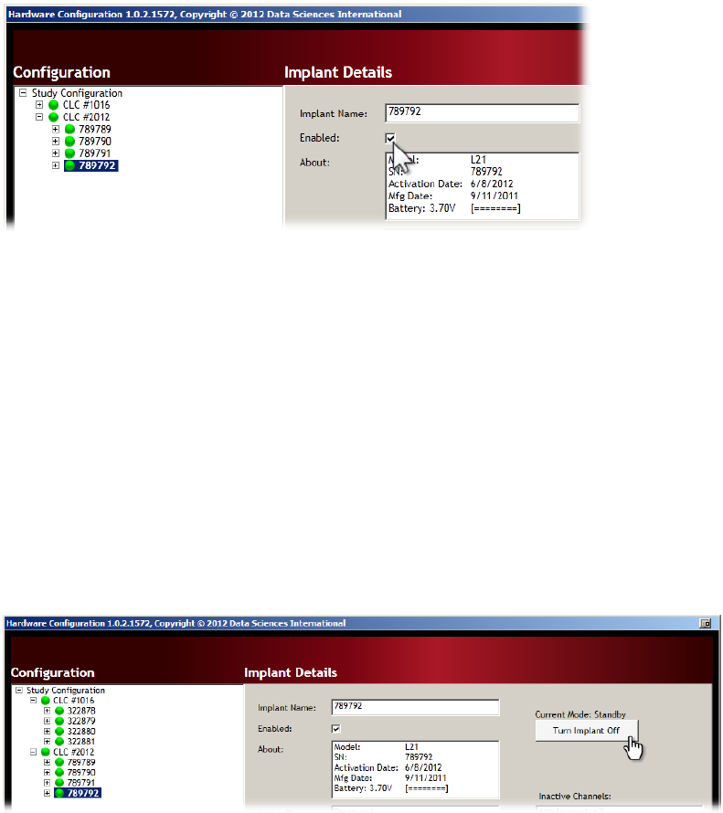
Enabled:
This check box will toggle the implant between ‘Enabled’ and ‘Disabled’ modes.
26•SoftwarePhysioTelDigitalConfigurationManual
• The Enabled mode allows the software system to record, store, and analyze data from the implant.
Ì WARNING: If the implant is not “Enabled” the device will still be in communication with the
system but no data from this implant will be visible to the analysis software.
Current Mode:
The Turn Implant Off button allows the user to remotely switch the implant to the OFF mode. Once in the
OFF mode, the implant cannot be remotely returned to the ON mode. The implant can only be turned ON by
physically passing a strong magnet close to the device for a few seconds.
Ì WARNING: Once the implant is switched OFF, it cannot be remotely turned back ON.
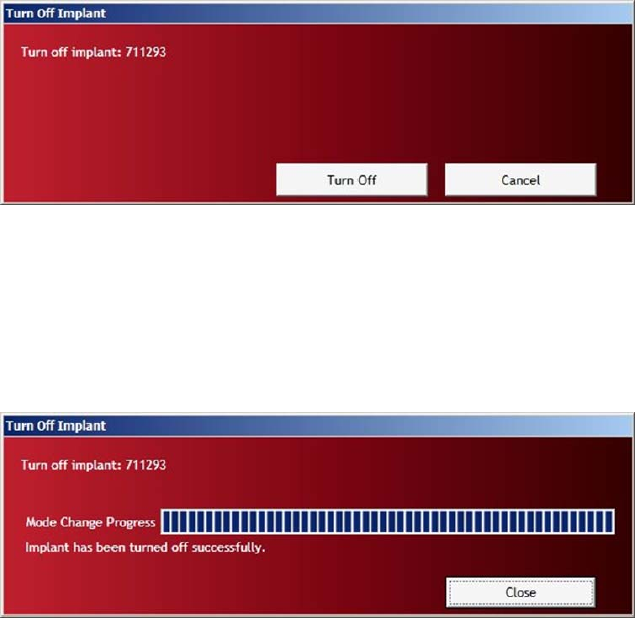
Procedure for switching the implant to the OFF mode:
1. Select the implant by clicking the line item in the Configuration column on the left of the screen.
2. Click the button labeled Turn Implant Off.
PhysioTelDigitalConfigurationManual Software•27
3. Confirm your intentions by clicking the button labeled Turn Off.
4. The progress bar will indicate the status of the operation. The completed process will be indicated by
the statement “Implant has been turned off successfully.”
5. Click the Close button to return to the Implant Details screen.
CAUTION: Once you turn off an implant it can only be returned to the ON state by physically
passing a strong magnet close to the implant device for a few seconds.
28•SoftwarePhysioTelDigitalConfigurationManual
Active Channels:
The Active Channels dialog allows the user to select which data collection channels are activated in the
implant. Active implant channels collect physiologic data and transmit the data through the acquisition
system to be stored in the data acquisition computer. Inactive channels do not collect physiologic data, those
particular implant functions are turned off.
In addition to avoiding the collection of unnecessary data, the in-activation of certain data channels has the
potential to preserve battery resources.
Channel Details
• Locate an implant by expanding the Study Configuration tree structure in the Configuration dialog
box. The tree structure can be expanded and contracted by clicking on the [+] and [-] icons to the left
of the individual line items.
• Click on the [+] icon to the left of implant name in the Configuration dialog box to view the implant
details.
• The current “active” channels are listed in bold type in the Configuration box once the tree structure
is fully expanded. The inactive channels are listed in italic text.
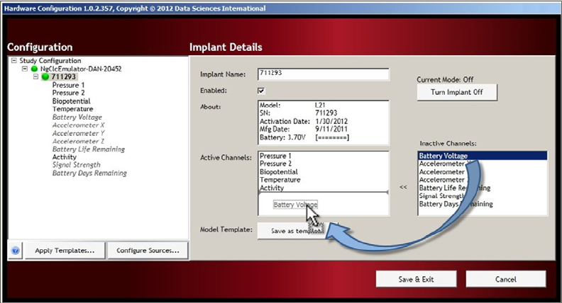
Activating Inactive Channels
• The default channels for the particular implant type are automatically listed in the Active Channels
dialog box in the center of the Implant Details screen.
PhysioTelDigitalConfigurationManual Software•29
• To activate an inactive channel, click on the desired channel label in the Inactive Channels: dialog
box, hold the mouse button, and drag the channel label to the Active Channels: dialog box. Release
the mouse button.
• To render a channel inactive, click and drag an active channel from the Active Channels: dialog to
the Inactive Channels: dialog.
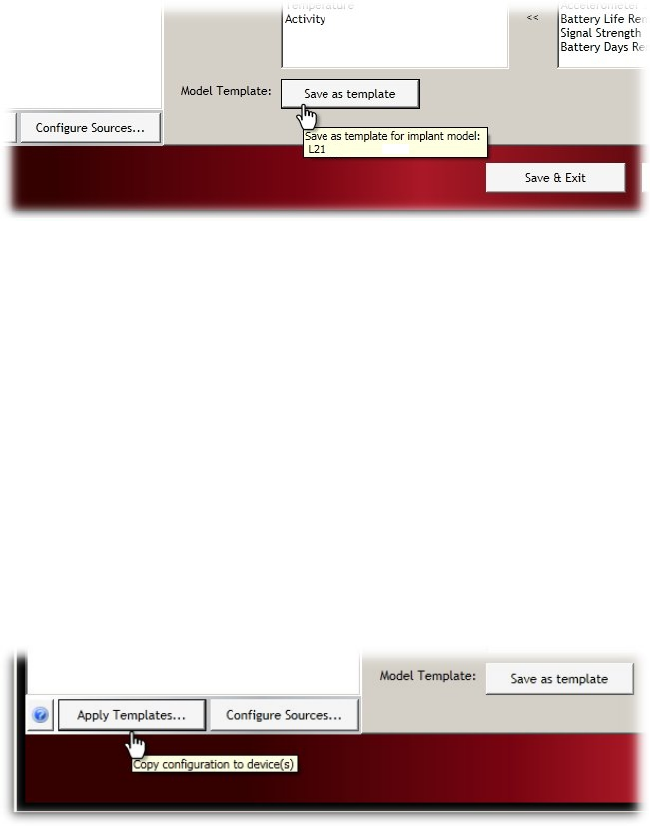
Model Template:
A Model Template can be created in order to identically configure a group of implants with the same channel
arrangement. Once the channel configuration is set for one of the implants, the user can save the channel
configuration as a template and apply that configuration template to all of the similar implants in a particular
study configuration.
1. Select an implant from the Configuration column on the left side of the screen.
2. Use the Active Channels dialog to configure the implant in the manner you wish to save as a
template.
NOTE: Only one Model Template can be saved per implant model type.
3. Click the Save as Template button.
30•SoftwarePhysioTelDigitalConfigurationManual
4. You will be offered a confirmation message “Are you sure you want to replace the template …?”
5. Click Yes to confirm.
Apply Templates:
Once an implant configuration is saved as a Model Template, that identical channel configuration can be
applied to any of the implants in the Study Configuration (provided that the implants are the same model
number).
To apply the saved template to other implants in the Configuration list:
1. Click the Apply Templates… button in the lower left corner of the window to open the Apply
Implant Channel Configuration screen.
2. Use the drop-down menu under Choose implant or template to apply: to select the saved template
you wish to apply to the other implants. It is also possible to copy the channel configurations from
one implant to another provided they are the same model type.
3. In the Apply channel configuration to: dialog box, select the individual implants to which the
template should be applied. Select the implants using the check boxes next to the implant label. The
Select All check box can be used to select/deselect all of the implants in the dialog box.
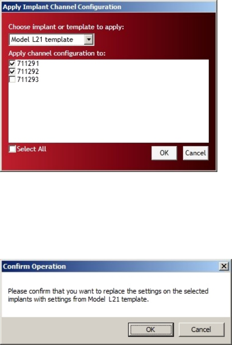
PhysioTelDigitalConfigurationManual Software•31
4. TheSelect Allcheckboxcanbeusedtoselect/deselectalloftheimplantsinthedialogbox.
5. Click OK to apply the saved template configuration.
6. A Confirm Operation dialog is offered as a precaution, click OK to accept.
Save and Exit
This completes the Hardware Configuration.
To save the configuration file and exit the configuration wizard, click the Save & Exit button.
32•SoftwarePhysioTelDigitalConfigurationManual
Selecting Implants
Once the implants are configured in the Hardware Configuration they will be available for data collection.
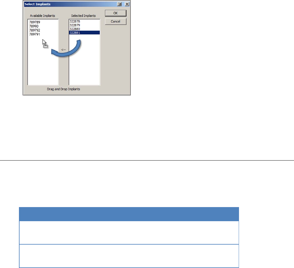
If the user does not wish to use all of the implants that are configured, the Select Implants option may be
used to select which implants will be available in the P3 Setup. The implants that are placed in the Selected
Implants column (right) will be passed through into the P3 Setup and will be available for acquisition. The
implants that are placed in the Available Implants column (left) will remain configured in the system but
will not be visible in the P3 Setup.
1. From the main Ponemah menu bar select Hardware\Select Implants…
2. The configured implants will appear in the Selected Implants column (right).
3. To de-select an implant for acquisition, click on the implant number in the right column and drag the
item into the left column titled Available Implants. Repeat this step for each implant number to be
moved.
PhysioTelDigitalConfigurationManual Software•33
4. Once all of the desired implants are moved, Click OK.
5. This closes the Hardware configuration process and return to the main Ponemah program.
Protocol Setup
P3 Setup allows the user to define the various acquisition settings for the sampling protocol. A default
Channel Input Setup is available for each of the PhysioTel Digital implants which automatically configures
the input channels for the most common PhysioTel Digital applications.
Model Pressure 1 Pressure 2 Biopotential Temperature Activity
L11
L21
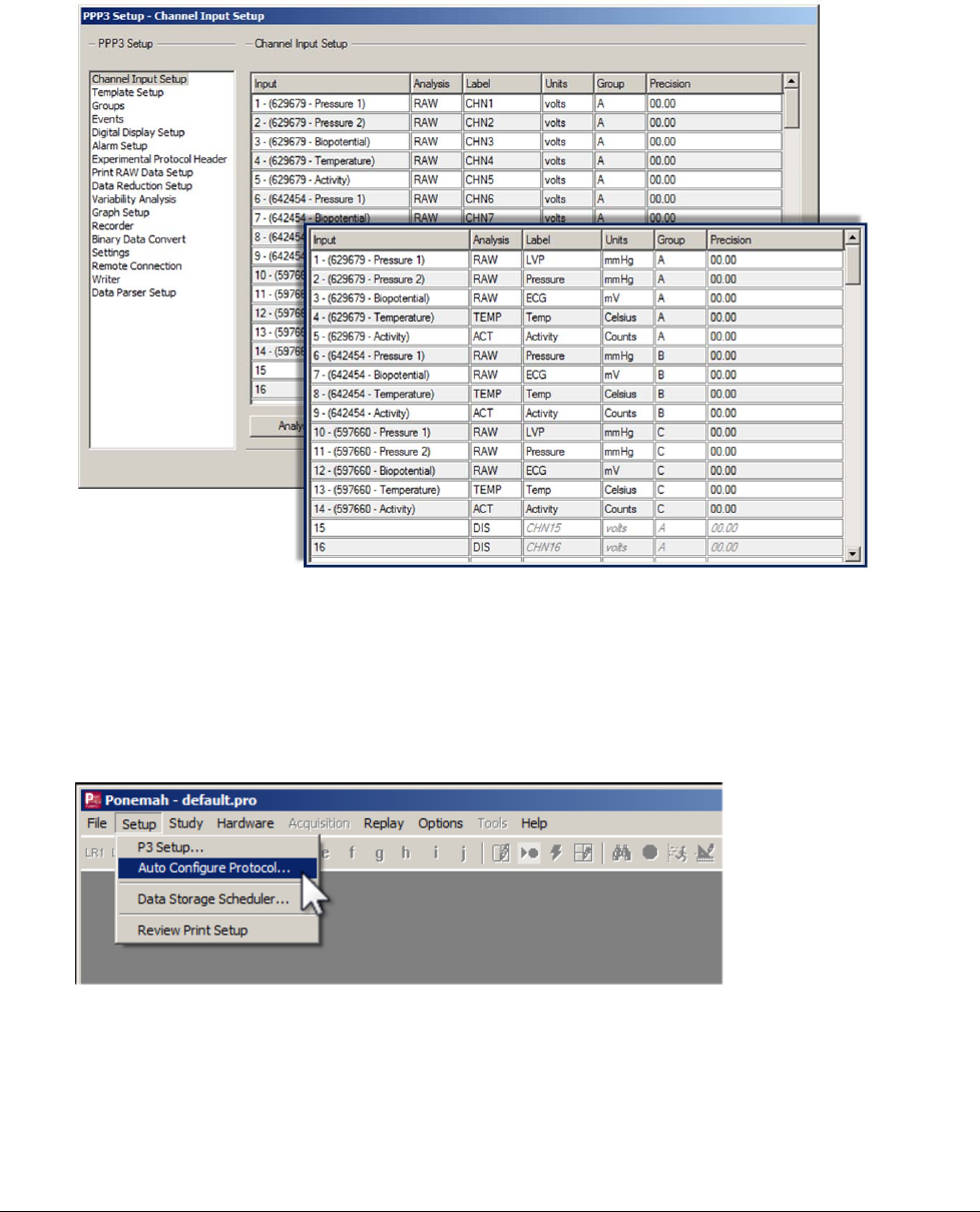
Without the Auto Configuration option the Channel Input Setup in Ponemah would have to be manually
configured item by item. The Auto Configure Protocol automatically labels and configures all of the implant
channels to their optimal settings.
34•SoftwarePhysioTelDigitalConfigurationManual
The results of the Auto Configure Protocol option are shown in the insert frame on the right.
To apply the automatic configuration option:
1. Select Setup\Auto Configure Protocol…
2. A cautionary message will be offered concerning overwriting of previous protocol files, to accept and
continue click Yes.
NOTE: For a more detailed description on the settings affected by the Auto Configure
Protocol feature or the acquisition settings defined within P3 Setup, please see the P3Plus
Manual.
Start Acquisition
The Start Acquisition command performs the following functions:
PhysioTelDigitalConfigurationManual Software•35
1. The data acquisition computer sends an implant Mode Change command to the CLC.
2. Ponemah starts displaying a countdown in the Implant Status screen.
3. The CLC configures the implants and sets the implant mode to Active.
4. The computer updates the implant status to Acquiring.
5. The implants start sending data packets to the CLC.
6. The CLC starts sending data packets to the computer.
7. The computer sends the data to Ponemah.
8. Ponemah begins displaying waveform data in P3P graphs.
Diagnostics
Accessing Diagnostics
The Diagnostics user interface is a browser based webpage that allows the user to check the status of the
PhysioTel Digital hardware components, update firmware, and perform diagnostic tests to optimize the
performance of the system components.
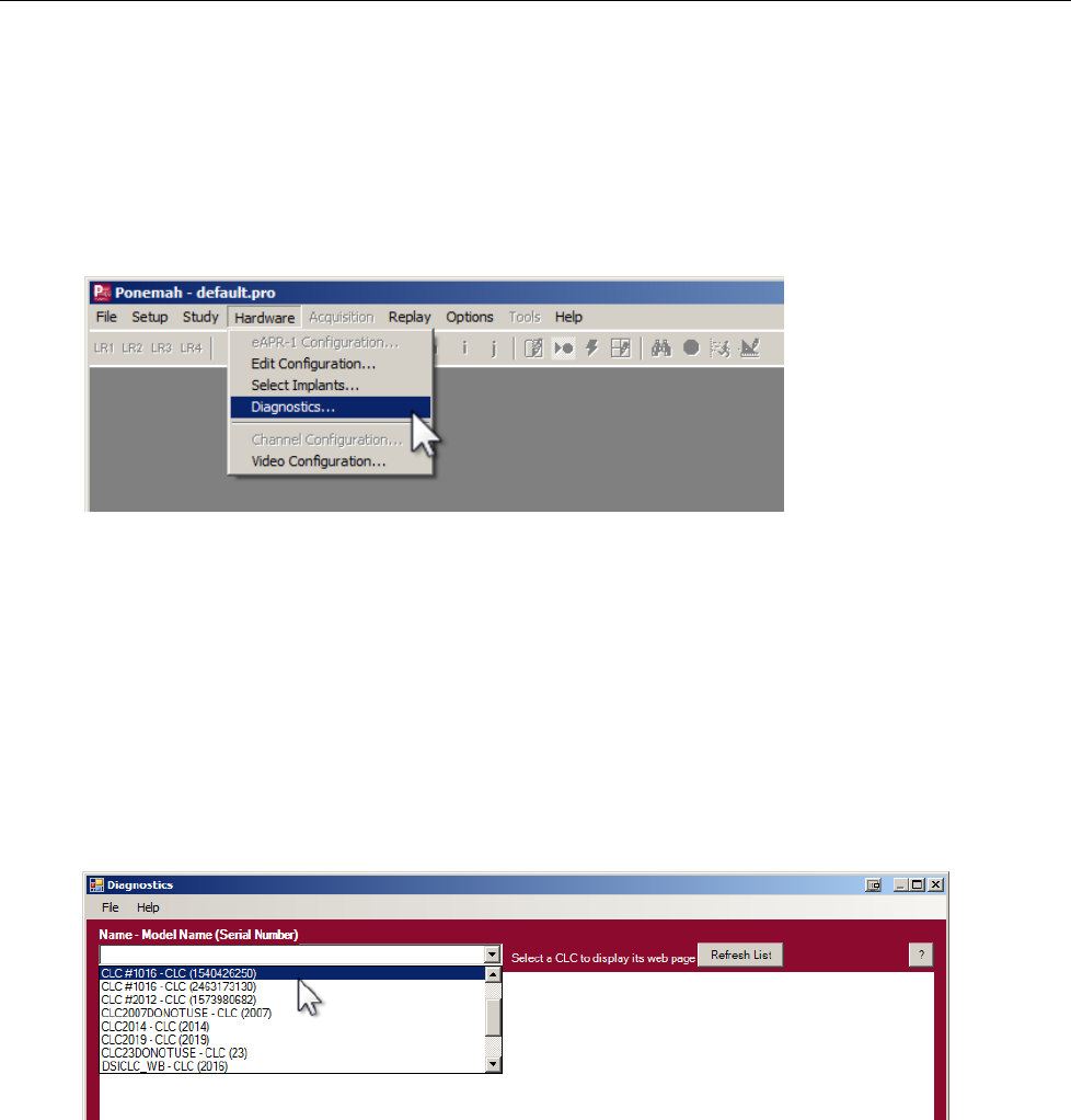
The Diagnostic user interface is accessed from the Ponemah Hardware menu.
• From the menu bar click Hardware, and select Diagnostics.
• This opens the Diagnostics Webpage in a dedicated browser window.
Diagnostics Webpage
The Diagnostics user interface is a browser based webpage that allows the user to check the status of the
PhysioTel Digital hardware components, update firmware, and perform diagnostic tests to optimize the
performance of the system components.
To select a specific CLC click on the drop-down menu located in the top left corner of the diagnostics
window. All of the configured CLCs that are connected to the system will appear in this list.
36•SoftwarePhysioTelDigitalConfigurationManual
CLC Options
The CLC Section of the Diagnostics webpage has the following sections:
• Home
• Network
• Upload CLC Firmware
• System Status
• Settings
• Reboot
Each of these will be described in a separate section below.
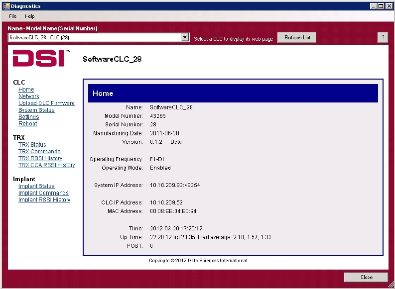
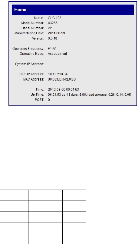
Home
PhysioTelDigitalConfigurationManual Software•37
• Name : User-selected name
• Model Number:
• Serial Number:
• Manufacturing Date: (Format = YYYY-MM-DD)
• Version:
• Operating Frequency: (Format = XX-YZ)
Region Frequency Group
F1 = US A 1
F2 = EU B 2
C
D
The frequencies are designated by four alpha-numeric characters XX-YZ (XX = region, Y = freq., Z = group).
NOTE: the Operating Frequency will read “Unknown” if CLC is powered up without a TRX
connected.
• Operating Mode: Enabled = Normal operational mode
Disabled = The CLC sends and receives no RF data
Assessment = the CLC monitors the RF field and collects RSSI data from
attached TRXs
• System IP Address: IP address of the data acquisition computer
• CLC IP Address: The IP address of this particular CLC
• MAC Address: Unique identifier for the CLC network interface
• Time: Current Date & Time (Format = YYYY-MM-DD HR:MN:SC)
• Up Time: Status information since last reboot
• POST: Power On Self Test (0 = Passed, OK …)
38•SoftwarePhysioTelDigitalConfigurationManual
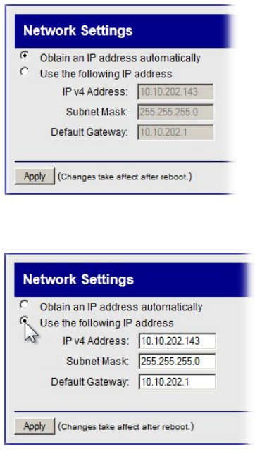
Network (Settings)
Obtain an IP address automatically
This is the normal operating mode for the CLC. With this option selected the CLC is queried and the values
that it reports back are displayed in the appropriate text boxes:
• IP v4 Address:
• Subnet Mask:
• Default Gateway:
NOTE: A new IP address can be generated by performing
an “extended” reset: push and hold the reset button on the
back of the CLC for 5-15 seconds.
Use the following IP address
If the user wishes to manually assign a specific IP address to the
CLC, click this radio button and type a new IP address in the text
box.
If you wish to perform this operation, follow this procedure:
1. Click the radio button for Use the following IP address
2. Enter the desired values in the text boxes labeled:
• IP v4 Address:
• Subnet Mask:
• Default Gateway:
3. Click Apply.
NOTE: A reboot of the system will have to be
performed in order for the new IP Address to
activate.
CAUTION: In the event that the user-assigned IP address is not accessible, this diagnostics
tool will lose contact with the CLC. To generate a new IP address, the user will have to
perform an “extended” reset: push and hold the reset button on the back of the CLC for 5-15
seconds.
PhysioTelDigitalConfigurationManual Software•39
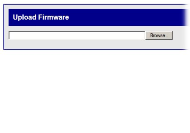
Upload CLC Firmware
This page allows the user to update the CLC firmware. From time to time it may be advantageous to upgrade
the internal read-only program instructions through a firmware upgrade. This often results in improved
performance.
To update or change the firmware version in the CLC, follow this procedure:
1. Click on the Browse button and use the file upload window to locate the firmware file.
2. Navigate to the specific filename and click Open
3. Message 1: Uploaded, Validating
4. Message 2: Validated. Upgrade will be applied during reboot.
NOTE: A reboot of the system will have to be performed in order for the update to activate.
40•SoftwarePhysioTelDigitalConfigurationManual
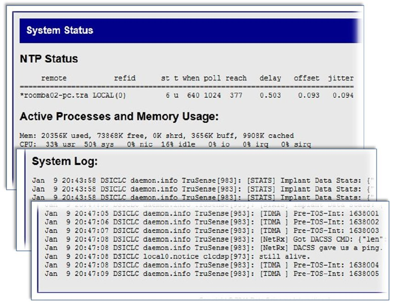
System Status
The System Status is a continuously updating “log” file of the CLC’s communication activity. It can be used
to monitor communication issues in the event of discontinuities.
Contents:
• NTP Status – Reports the last time the CLC received an update from the NTP Server
• Active Processes and Memory Usage
• System Log
PhysioTelDigitalConfigurationManual Software•41
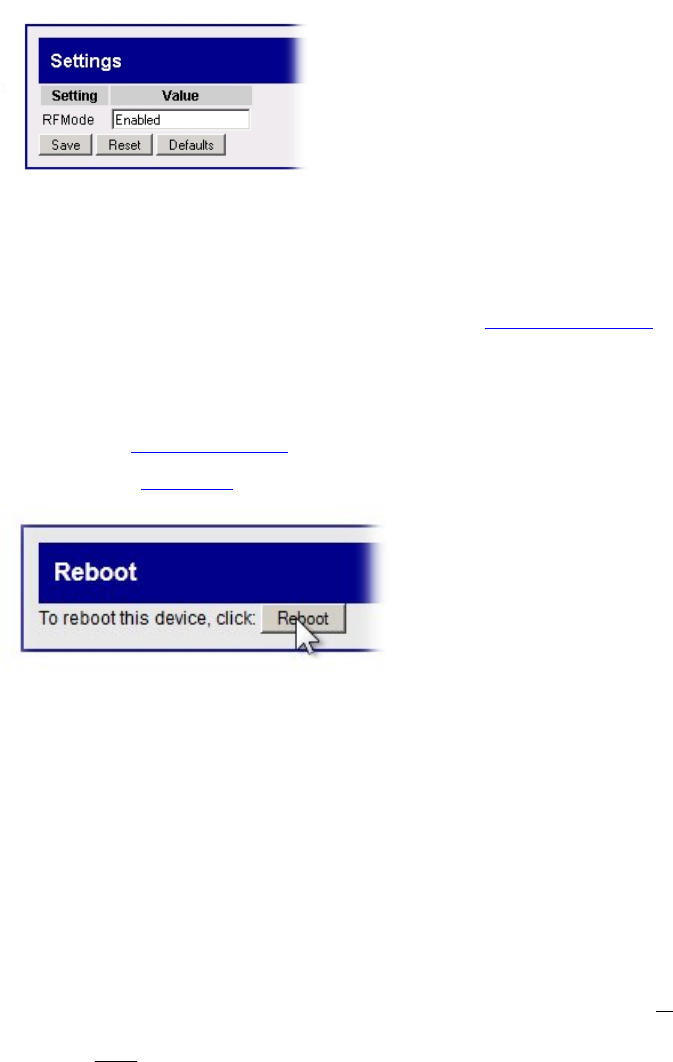
Settings
The Settings page allows the user to monitor the RF Mode.
• Enabled – Normal operating mode
• Disabled – Halts communication between the TRXs and the implants
• Assessment – Allows the user to sample individual frequencies to assess the level of background RF
interference. The Assessment mode is used for the TRX RSSI History function
Reboot
This function allows the user to perform a complete reboot of the CLC. A Reboot of the system is required to:
• Activate a firmware upgrade
• Change the IP settings
• To reboot the CLC left click the Reboot button
NOTE: the Reboot process may take several minutes to
complete. There are no progress indicators that appear on
this page, However there are indicator lights on the back
of the CLC box itself.
TRX Options
The TRX is the three letter designation for a Transceiver: the component in the system that receives Radio-
Frequency (RF) signals and converts it into digital form that is sent, via cable, to the Communication Link
Controller; additionally, the component that transmits Radio-Frequency signals converted from digital form
sent via cable, from the Communication Link Controller
42•SoftwarePhysioTelDigitalConfigurationManual
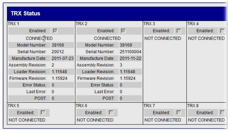
TRX Status
The TRX Status screen is a non-interactive snapshot of the current status of the TRXs that are connected to
the CLC. Each CLC is capable of interfacing with eight TRXs. This arrangement follows the layout on the
rear panel of the CLC unit.
TRX Status screen indicating that two TRX units are connected and enabled.
The line items are as follows:
TRX (#): Number 1-8
Enabled: A check mark in the box indicates that the TRX is connected and
available to communicate with the implants
Connected: Indicates whether the TRX is physically CONNECTED or NOT
CONNECTED to the CLC
Model Number:
Serial number:
Manufacture Date: YYYY-MM-DD
Assembly Revision:
Loader Revision:
Firmware Revision:
Error Status: Indicates that at least one error has occurred
Last error: The most recent error encountered
POST: Power On Self Test (0 =Passed, OK)
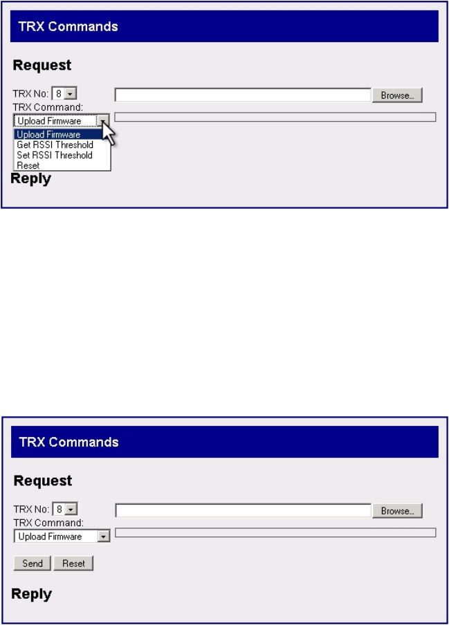
TRX Commands
This dialog screen allows the user to perform two functions that affect the performance of the TRX. The user
can upload a different version of the on-board read-only software (firmware). Additionally the user can adjust
the telemetry receiver thresholds to optimize RF communications.
There are four commands available in this window.
PhysioTelDigitalConfigurationManual Software•43
Upload Firmware
To update or change the firmware version in the TRX, follow these steps:
1. Click on the TRX No: drop-down menu and select the TRX number you wish to communicate with.
2. Click on the TRX Command: drop-down menu and select Upload Firmware.
3. Click on the Browse… button and use the file upload window to locate the firmware file.
4. Navigate to the specific filename and click Open
5. Message 1: Uploaded.
6. Message 2: Validating
7. Message 3: Updating TRX Firmware...
8. Message 4: Command Completed
44•SoftwarePhysioTelDigitalConfigurationManual
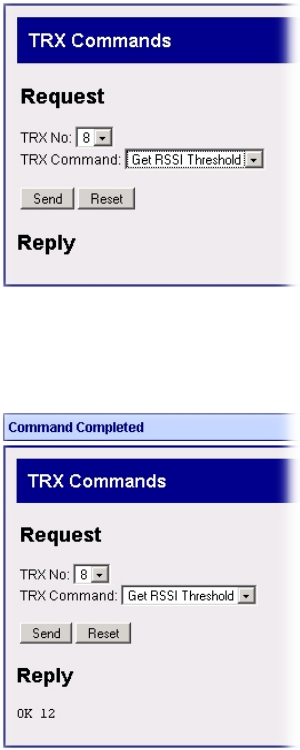
Get RSSI Threshold
RSSI stands for Received Signal Strength Indicator. It is a quantitative measure of the strength of the RF
signal that the TRX is receiving from the implants. The Get RSSI Threshold command retrieves the current
threshold value from the TRX. The default value = 12
1. Select Get RSSI Threshold from the TRX Command: drop-down menu.
2. Click Send.
3. A successful operation is indicated by a blue colored Command Completed banner at the top of the
screen and a text string below the word Reply at the bottom of the screen.
4. The reported text value OK “xx” is the Hexadecimal value of the RSSI Threshold.
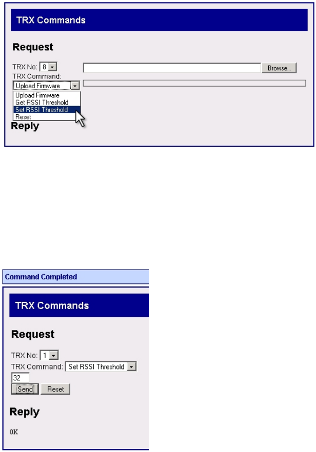
Set RSSI Threshold
RSSI stands for Received Signal Strength Indicator. It is a quantitative measure of the strength of the RF
signal that the TRX is receiving from the implants. The Set RSSI Threshold command allows the user to
adjust the lower limit of signal strength that the TRX will accept as viable information from the implants.
The default value = 12
PhysioTelDigitalConfigurationManual Software•45
NOTE: Anytime the TRX is unplugged, or the CLC is rebooted, the RSSI threshold value will revert
back to the hexadecimal default value of 0x12.
1. Select Set RSSI Threshold from the TRX Command: drop-down menu.
2. Select the TRX # from the TRX No: drop-down menu.
3. Enter a hexadecimal value in the small text box above the Send button.
4. Click the Send button.
5. A successful operation is indicated by a blue colored Command Completed banner at the top of the
screen and a text string “OK” below the word Reply at the bottom of the screen.
46•SoftwarePhysioTelDigitalConfigurationManual
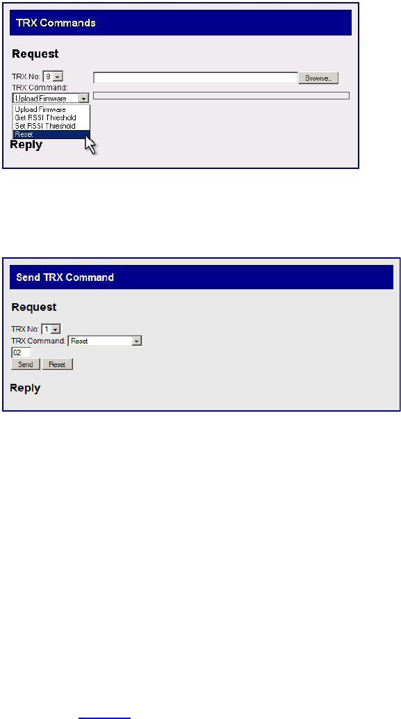
Reset
The Reset function returns the TRX settings to the factory default values.
1. Select Reset from the TRX Command: drop-down menu.
2. Select the TRX # from the TRX No: drop-down menu.
3. Change the value in the dialog box below the letters TRX from “ff” to “02”.
4. Click the Send button.
5. A successful operation is indicated by a blue colored Command Completed banner at the top of the
screen and a text string “OK” below the word Reply at the bottom of the screen.
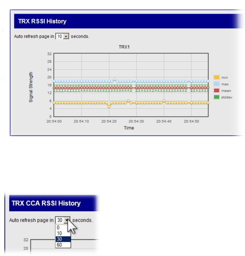
TRX RSSI History
This option allows the user to sample how well the TRXs are receiving RF signals from the implants. In an
actively running system these graphs continually update according to a user prescribed auto refresh rate.
There will be one RSSI graph displayed for each of the enabled TRXs connected to the CLC. The TRXs will
average the received signals from all of the implants it is communicating with. It will then average the
implant signals and report an average value for each graph.
Follow this procedure to utilize the TRX RSSI History option:
1. Click on the Settings link under the CLC Options heading.
2. In the text box to the right of the words RF Mode, delete the word “Enabled”
3. Type the word “Assessment” in the text box and press click the Save button below.
4. Using the mouse cursor, click on the link marked TRX RSSI History.
PhysioTelDigitalConfigurationManual Software•47
5. This will open the RSSI graph screen.
Warning! When you are finished with the TRX RSSI History function you MUST return the
CLC to the “Enabled” mode!
6. Click on the Settings link under the CLC Options heading.
7. Return to the text box delete the word “Assessment”
8. Type the word “Enabled” in the text box and press click the Save button below.
9. Verify the CLC status by Home link under the under the CLC options heading.
10. The Operating Mode: line item in the center of the screen should read Enabled, if it does not, repeat
steps 6-9 above.
Graphical representation of the average strength of the signals received from the implants
• To set the auto refresh rate of the graph click on the drop-down menu at the top of the screen and
select a new value.
48•SoftwarePhysioTelDigitalConfigurationManual
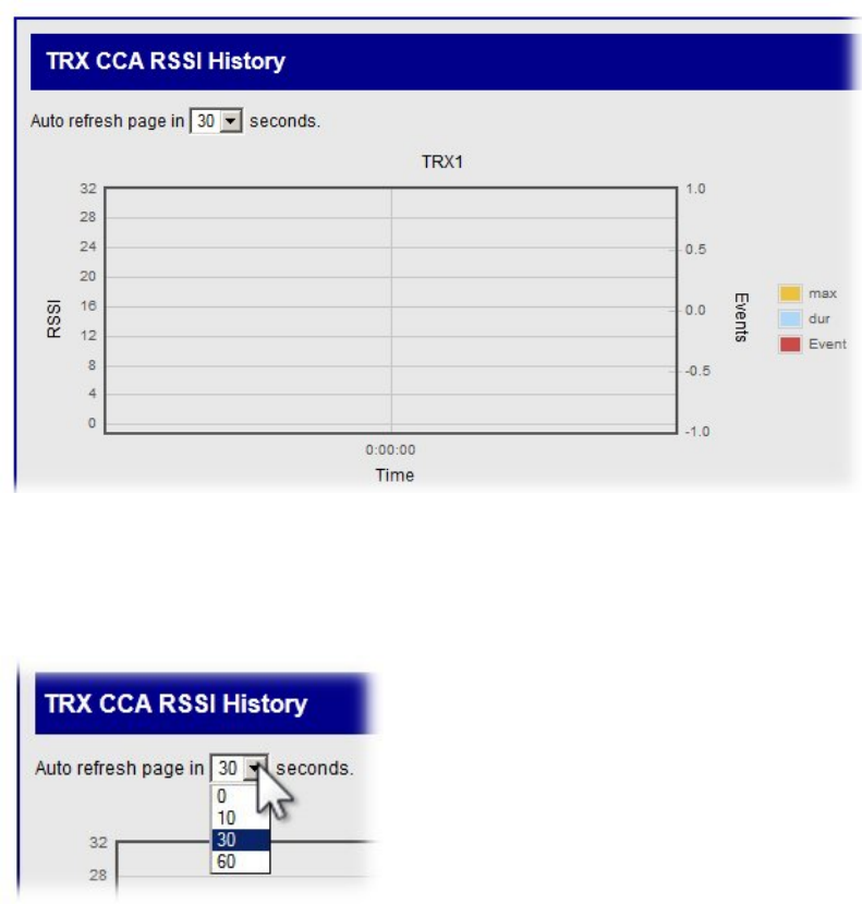
TRX CCA RSSI History
CCA is an acronym for Clear Channel Assessment. According to certain RF regulation environments, it is
necessary to invoke a “listen before you talk” policy. The Clear Channel Assessment operation determines
whether the wireless medium is busy or idle. The CLC can then make a decision on whether to attempt
communication.
The CLC will display the RSSI value of what the TRX is receiving. If the TRX picks up a significant signal
from a competing device the CLC delays the transmission of a command to the implant. If the interfering
signal persists, communication with the implants may be disrupted.
• The CLC will try to avoid talking in a noisy RF environment.
• The CLC will display an RSSI value of what the TRX is picking up in the Join window.
• In Europe the “Listen Before Talk” function is enabled by default.
• In the United States the “Listen Before Talk” function is disabled by default.
• There will be one plot for each of the TRXs assigned to the CLC.
• To set the auto refresh rate of the graph click on the drop-down menu at the top of the screen and
select a new value.
PhysioTelDigitalConfigurationManual Software•49
Implant Options
In this document the term “implant” refers to a PhysioTel Digital Telemetry Transmitter.
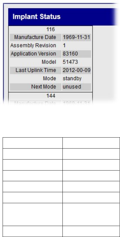
Implant Status
Implant Status is a non-interactive table which reports the operational status of all of the implants that are
communicating with a CLC.
There will be one eight-row table for each implant. The content of the rows is as follows:
Serial Number
Manufacture Date YYYY-MM-DD
Assembly Revision
Application Version
Model
Last Uplink Time YYYY-MM-DD
Mode standby
active
unused
Next Mode
Definitions:
• Last Uplink Time – The latest time that the CLC received an uplink from the implant.
• Mode Options:
50•SoftwarePhysioTelDigitalConfigurationManual
o Standby – not actively transmitting data
o Active – actively transmitting data
o Unused – configured but probably out of range
• Next Mode: (This feature is not yet implemented).
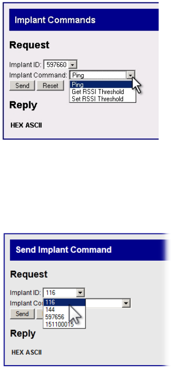
Implant Commands
There are three commands with which the user can communicate with individual implants. They are Ping;
Get RSSI Threshold; and Set RSSI Threshold.
• The Ping command allows the user to select an individual implant and request a confirmation
message that the implant is operating within range.
• The Get RSSI Threshold command retrieves the current threshold value from the implant.
• The Set RSSI Threshold command allows the user to adjust the lower limit of signal strength that
the implant will accept as viable information from any of the TRXs.
The “Ping” Command
The Ping command allows the user to send a request to an individual implant to reply with a confirmation
message that the implant is operating within range.
• Click on the drop-down menu labeled Implant ID:
• Select a device by left clicking on an implant serial number.
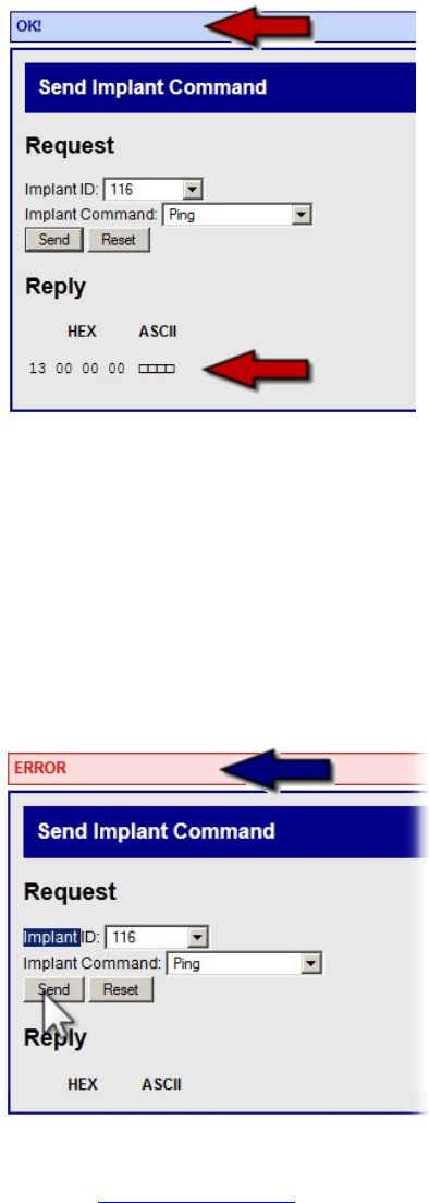
PhysioTelDigitalConfigurationManual Software•51
• Click on the drop-down menu labeled Implant Command.
• Left click the Ping command
• Click the Send button
If the Ping dialog is successful:
• A blue colored banner with the word OK! will appear at the top of the screen.
• The implant will report back with a Hexadecimal value which is displayed in the Reply table at the
bottom of the screen.
If the Ping dialog is unsuccessful:
The Ping will be automatically repeated several times.
• A red colored banner with the word ERROR will appear at the top of the screen.
• The more common error codes are listed at the end of this section.
52•SoftwarePhysioTelDigitalConfigurationManual
• The implant will not report with a Hex value at the bottom of the screen.
NOTE: It may take several seconds for an unsuccessful Ping command to generate an error message
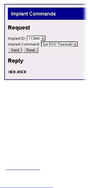
Get RSSI Threshold
The Get RSSI Threshold command retrieves the current threshold value from the implant. Get RSSI
Threshold reads the signal strength value that allows the implant to hear commands from the CLC/TRX.
1. Click on the drop-down menu labeled Implant ID:
2. Select a device by left clicking on an implant serial number.
3. Click on the drop-down menu labeled Implant Command.
4. Left click the Get RSSI Threshold command.
5. Click the Send button
6. A successful operation is indicated by a blue colored OK banner at the top of the screen.
7. A Hexadecimal value will also be reported in a table below the word Reply.
8. If the command cannot be successfully completed an error code may be displayed. Refer to the
common error codes below.
Set RSSI Threshold
RSSI stands for Received Signal Strength Indicator. It is a quantitative measure of the strength of the RF
signal that the TRX is receiving from the implants. The Set RSSI Threshold command allows the user to
adjust the lower limit of signal strength that the implant will accept as viable information from the CLC/TRX.
1. Click on the drop-down menu labeled Implant ID:
2. Select a device by left clicking on an implant serial number.
3. Click on the drop-down menu labeled Implant Command.
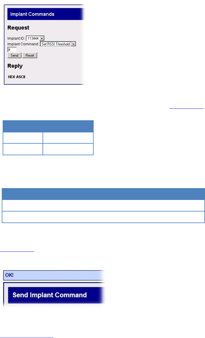
PhysioTelDigitalConfigurationManual Software•53
4. Left click the Set RSSI Threshold command.
5. A small text-entry box will appear below the Implant Command: line.
6. Allowable values for RSSI Threshold (values must be entered in Hexadecimal format).
Decimal Hexadecimal
12 0C
28 1C
7. Adjusting the RSSI Threshold value will affect the implant performance in the following manner.
RSSI value Sensitivity Range RF performance
Increase Decrease Decrease Increase
Decrease Increase Increase Decrease
8. Enter a new value for the RSSI Threshold and click the Send button (values must be entered in
Hexadecimal format).
9. A blue colored banner with the word OK! will appear at the top of the screen.
10. Repeat the Get RSSI Threshold procedure for verification.
11. If the command cannot be successfully completed an error code may be displayed. Refer to the
common error codes below.
54•SoftwarePhysioTelDigitalConfigurationManual
Common Error Codes
The implant commands in this section are capable of generating an error code if the command cannot be
successfully executed. Below is a list of the more common error codes.
Error code Description Solution
900 Unknown Error
901 Implant Not Found Make sure implant in range
902 Timeout Make sure implant in range
903 Send Fail Make sure implant in range, in standby mode, Ponemah
is not trying to send a lot of commands to the implant
905 Implant in Active Mode Make sure the implant is in standby mode
906 Queue Full Make sure implant is in range, Ponemah is not trying to
send a lot of commands to the implant
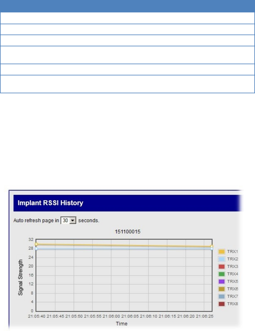
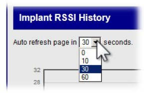
Implant RSSI History
Similar to the TRX RSSI History, the Implant RSSI History generates graphs in which the received signal
strength from each of the implants is plotted for each implant. These graphs allow the user to track how well
the implants are being received by each of the TRXs. In an actively running system these graphs continually
update according to a user prescribed auto refresh rate.
• There will be one RSSI graph for each of the recognized implants in the system.
• Each implant will report the received signal strength from each of the TRXs it is communicating with.
The RSSI graph will display one data set for each of the TRXs.
PhysioTelDigitalConfigurationManual Software•55
• To Set the Auto refresh rate of the graph, click on the drop-down menu at the top of the screen and
select a new value.
56•GlossaryPhysioTelDigitalConfigurationManual
Glossary
1. CCA = Clear Channel Assessment: The clear channel assessment operation determines whether the
wireless medium is busy or idle. The MAC layer can then make a decision on whether to send a frame.
2. CLC = Communication Link Controller: Processes telemetered data to/from the TRX for communications
over the Ethernet connection.
3. Firmware: The combination of a hardware device and computer instructions and data that reside as read-
only software on that device.
4. IP Address = Internet Protocol address is a numerical label assigned to each device participating in a
computer network that uses the Internet Protocol for communication.
5. Listen Before Talk (LBT), or sometimes called Listen Before Transmit: A technique used in radio
communications whereby a radio transmitter first senses, or surveys, the radio environment before it starts
a transmission.
6. MAC Address = Media Access Control Address: A unique identifier assigned to network interfaces for
communications on the physical network segment.
7. RSSI = Received Signal Strength Indicator (or Indication): A signal or circuit that indicates the strength
of the incoming (received) signal in a receiver.
8. TRX = Transceiver: Component that receives Radio-Frequency signals and converts it into digital form
that is sent, via cable, to the Communication Link Controller; additionally, the component that transmits
Radio-Frequency signals converted from digital form sent via cable, from the Communication Link
Controller.

PhysioTelDigitalConfigurationManual Appendices•57
Appendices

PhysioTelDigitalConfigurationManual •59
Appendix A: Hexadecimal Conversion
Hexadecimal is base 16.
Base 16 is where the 'numbers' you can use are zero through to the letter F (0123456789ABCDEF). i.e. the
decimal value for '1' is represented in hexadecimal as '1' but the hexadecimal value of '15' (decimal) is shown
as 'F' (hexadecimal) and the value of '17' (decimal) is '11' in Hexadecimal.
Decimal Hex Decimal Hex Decimal Hex
1 1 11 B 30 1E
2 2 12 C 40 28
3 3 13 D 50 32
4 4 14 E 60 3C
5 5 15 F 70 46
6 6 16 10 80 50
7 7 17 11 90 5A
8 8 18 12 100 64
9 9 19 13 500 1F4
10 A 20 14 1000 3E8
PhysioTelDigitalConfigurationManual•61