Datalogic ADC DLBTMCX Datalogic Bluetooth Module User Manual DLBTMCX Users Guide 10 23 09
Datalogic ADC, Inc. Datalogic Bluetooth Module DLBTMCX Users Guide 10 23 09
Contents
- 1. Installation to host device
- 2. User manual-RF module
User manual-RF module
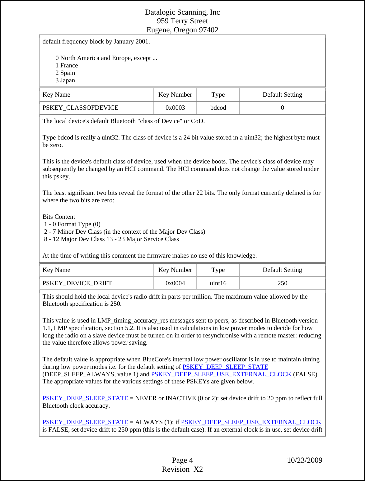
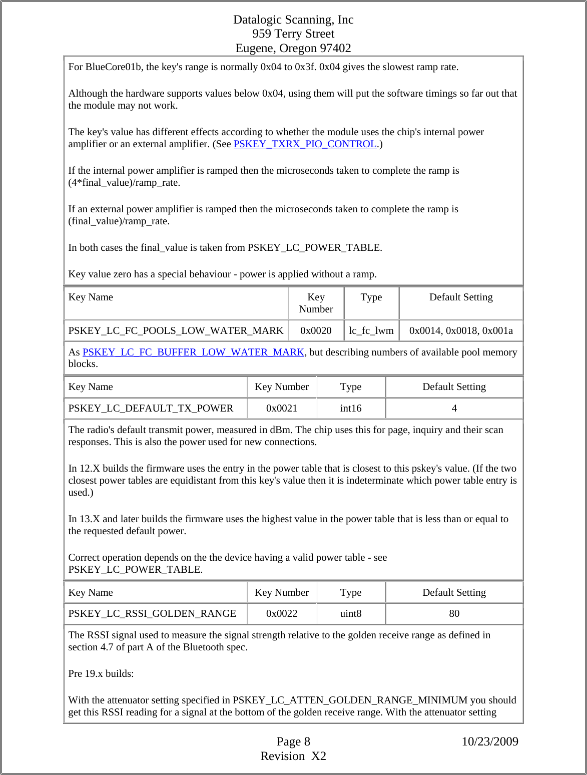
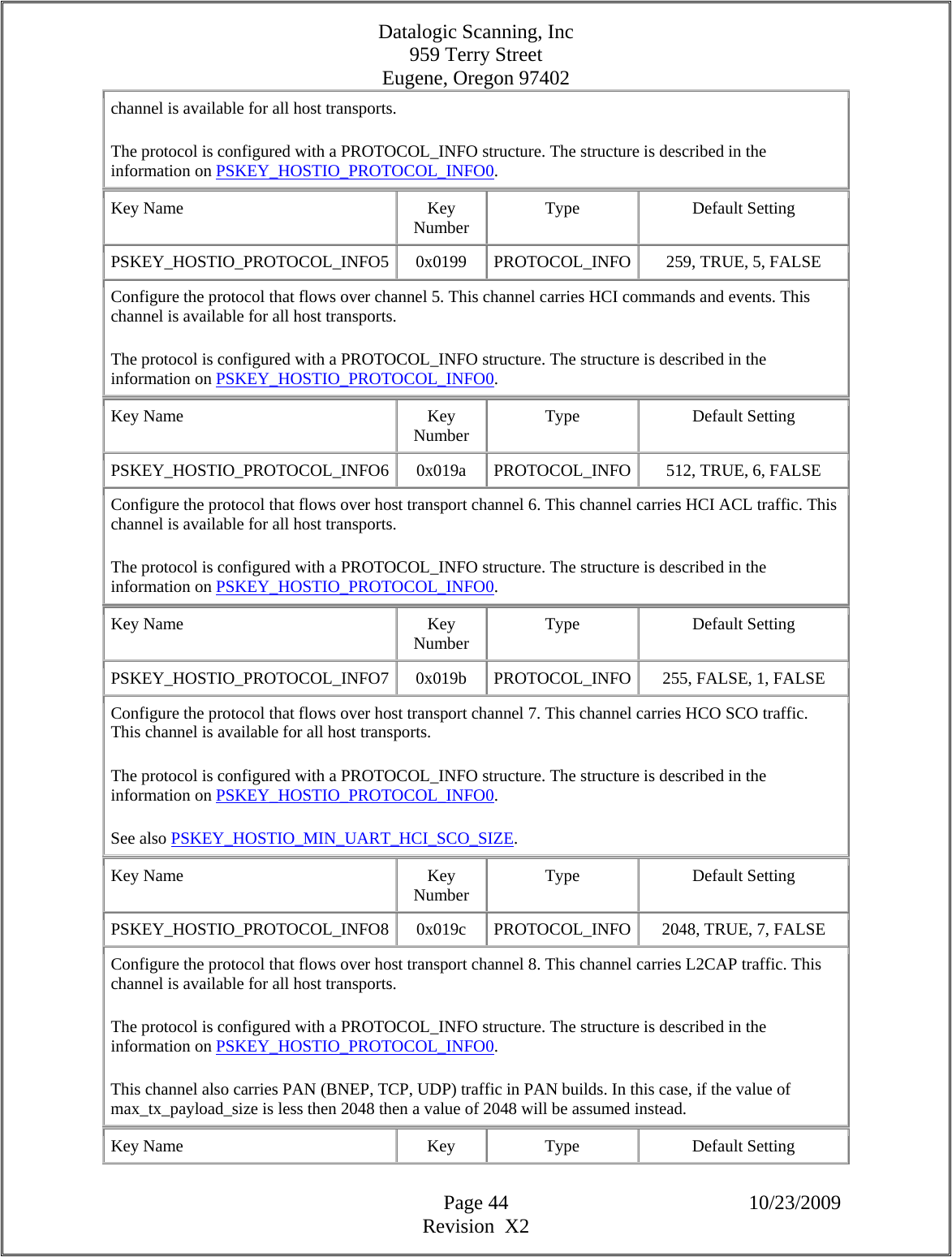
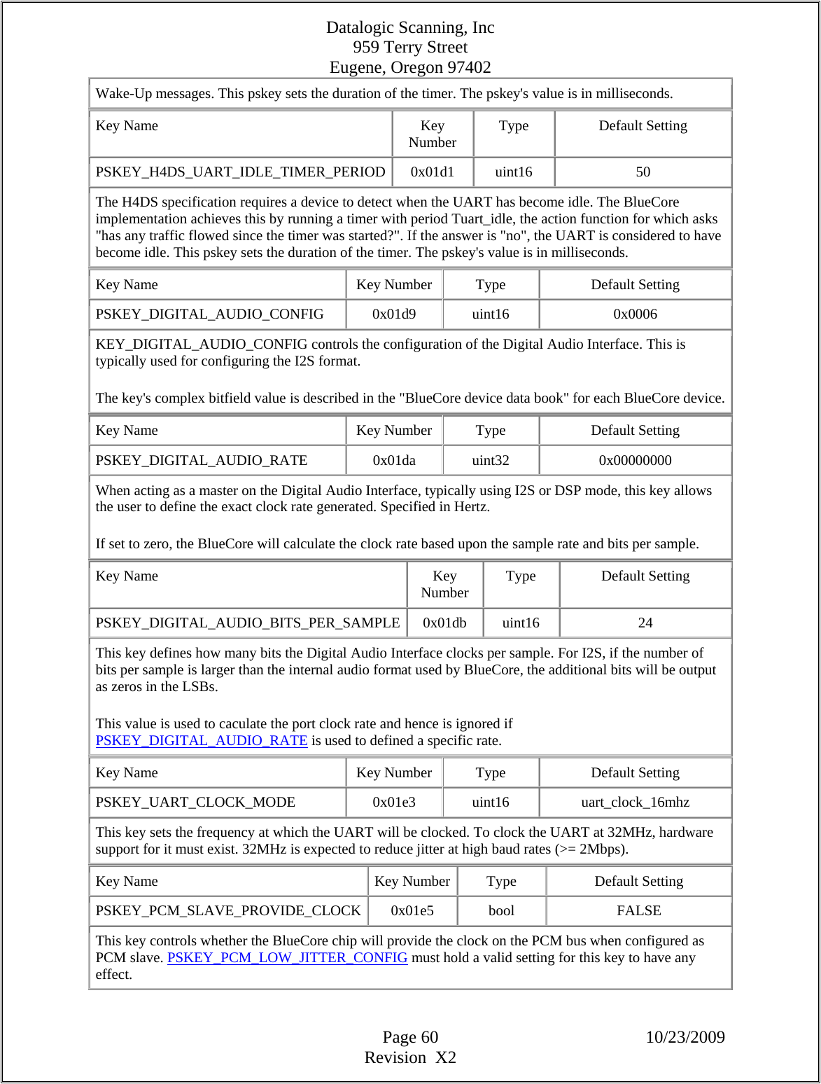
![Datalogic Scanning, Inc 959 Terry Street Eugene, Oregon 97402 Page 3 10/23/2009 Revision X2 2. µP Interface This design will be HCI only using the H4 protocol for serial communications. The baud rate will be set at 115.2K. 3. Persistence Storage Keys The following is a table covering the PS Key addresses and settings for each location. Please refer to the latest CSR document for updated PS Key settings. Key Name Key Number Type Default Setting PSKEY_BDADDR 0x0001 bdaddr 0x00A5A5, 0x5b, 0x0002 The local device's Bluetooth address. This should be unique to this device - allocated during manufacturing. The type bdaddr can be viewed as a uint16[4] array: 1st uint16: The top 8 bits of the LAP are in the bottom 8 bits of this word. The top 8 bits of this word must be zero. 2nd uint16: lower 16 bits of the LAP 3rd uint16: The 8 bit UAP is in the bottom 8 bits of this word. The top 8 bits of this word must be zero. 4th uint16: 16 bit NAP For example, the Bluetooth address 123456789abc is encoded as 0078, 9abc, 0056, 1234. The default value of this key is one of CSR's legal addresses: 00025b00a5a5. As stated in the Bluetooth specification, LAP values from 9e8b00 up to, and including, 9e8b3f must not be used as this range is reserved for inquiry access codes (IACs). Bluetooth module manufacturers must obtain their own block of addresses from the Bluetooth SIG/IEEE. If CSR's experience is typical, these authorities define the NAP and UAP, allowing manufacturers to set the 24 bit LAP. Key Name Key Number Type Default Setting PSKEY_COUNTRYCODE 0x0002 uint16 0 North America and most of Europe use a particular block of 79 radio frequencies for Bluetooth, but not all countries allow use of these frequencies. Some countries allow the use of different blocks of frequencies. This key selects the frequency blocks used by these exceptional countries. Over time most countries are adopting the default 79 frequency block, so the need for this value is diminishing. At the time of writing this comment it is expected that France, Spain and Japan will use the](https://usermanual.wiki/Datalogic-ADC/DLBTMCX.User-manual-RF-module/User-Guide-1192966-Page-3.png)
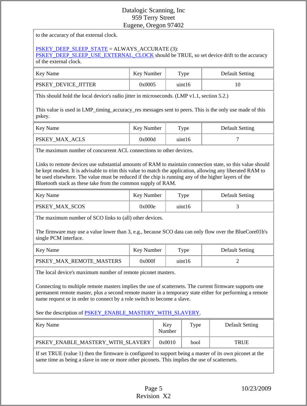
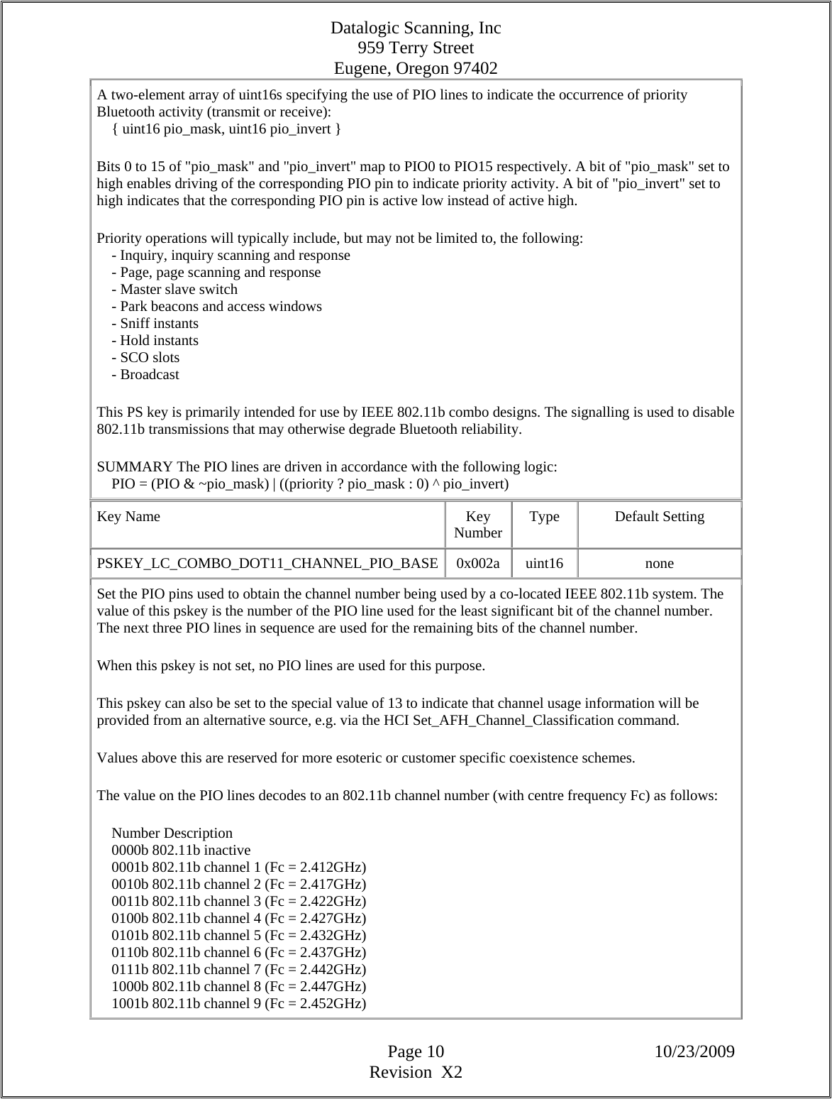
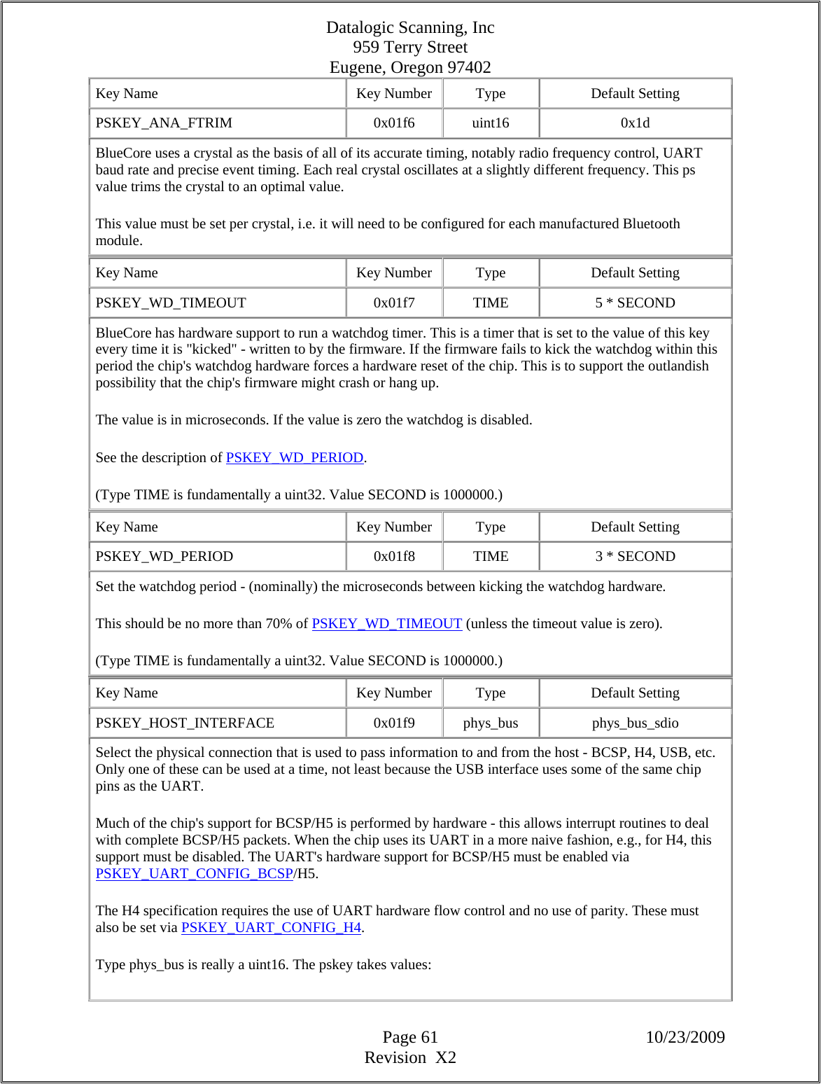
![Datalogic Scanning, Inc 959 Terry Street Eugene, Oregon 97402 Page 9 10/23/2009 Revision X2 specified in PSKEY_LC_ATTEN_GOLDEN_RANGE_MAXIMUM you should get this RSSI reading for a signal at the top of the golden receive range. Taking this signal above 90 can lead to faulty behaviour. If a -60 dBm signal with an attenuation of 1 gives an RSSI above 90 then leave this setting at 90 as you have a module with good sensitivity. By leaving this setting at 90 devices you're talking to will be able to lower their transmit power and thus reduce interference between units. 19.x builds and some 20.x builds: In builds where PSKEY_LC_ATTEN_GOLDEN_RANGE_MINIMUM and PSKEY_LC_ATTEN_GOLDEN_RANGE_MAXIMUM have been removed, this should be the RSSI reading at zero attenuator setting when the received power is at the bottom of the golden range. The top of the golden range is placed 20 dBm above this. 21.x builds and some 20.x builds: In builds where PSKEY_PREFERRED_MIN_ATTENUATION exists, with the attenuator setting specified in PSKEY_PREFERRED_MIN_ATTENUATION, you should get an RSSI value of PSKEY_LC_RSSI_GOLDEN_RANGE for a signal at the bottom of the golden receive range. The top of the golden range is placed 20 dBm above this. Key Name Key Number Type Default Setting PSKEY_LC_COMBO_DISABLE_PIO_MASK 0x0028 uint16[] none A three-element array of uint16s specifying the use of PIO lines to disable non-priority Bluetooth transmissions: { uint16 pio_mask, uint16 pio_invert, uint16 pio_logic } Bits 0 to 15 of "pio_mask" and "pio_invert" map to PIO0 to PIO15 respectively. A bit of "pio_mask" set to high enables use of the corresponding PIO pin to disable Bluetooth transmit. A bit of "pio_invert" set to high indicates that the corresponding PIO pin is active low instead of active high. If the "pio_logic" value is zero then any combination of the PIO lines being asserted will disable Bluetooth transmissions (logical OR), otherwise all of the specified PIO lines must be asserted to disable transmissions (logical AND). This PS key is primarily intended for use by IEEE 802.11b combo designs. The signalling is used to disable Bluetooth transmissions that may degrade 802.11b throughput. Summary: Non-priority Bluetooth transmissions are disabled in accordance with the following logic: masked = (PIO ^ pio_invert) & pio_mask disable = pio_logic ? masked != 0 : masked == pio_mask Key Name Key Number Type Default Setting PSKEY_LC_COMBO_PRIORITY_PIO_MASK 0x0029 uint16[] none](https://usermanual.wiki/Datalogic-ADC/DLBTMCX.User-manual-RF-module/User-Guide-1192966-Page-9.png)
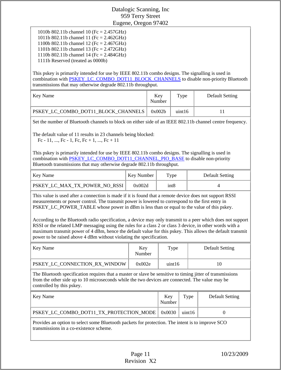
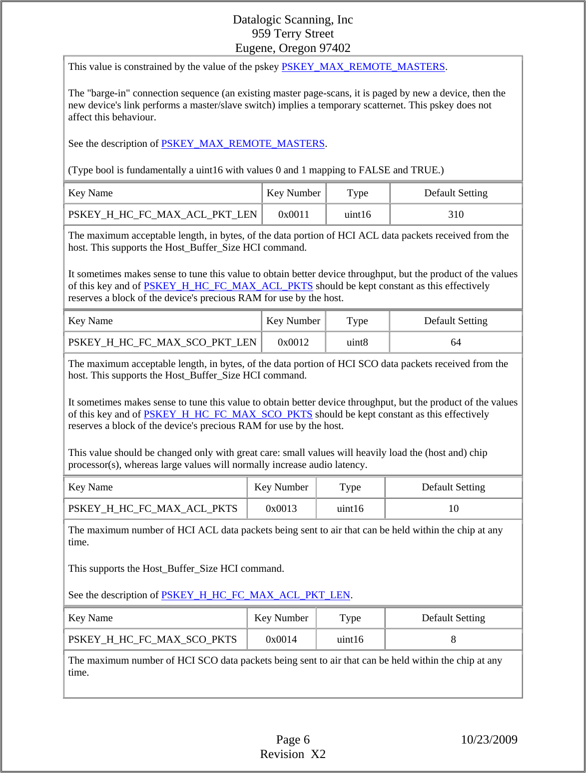
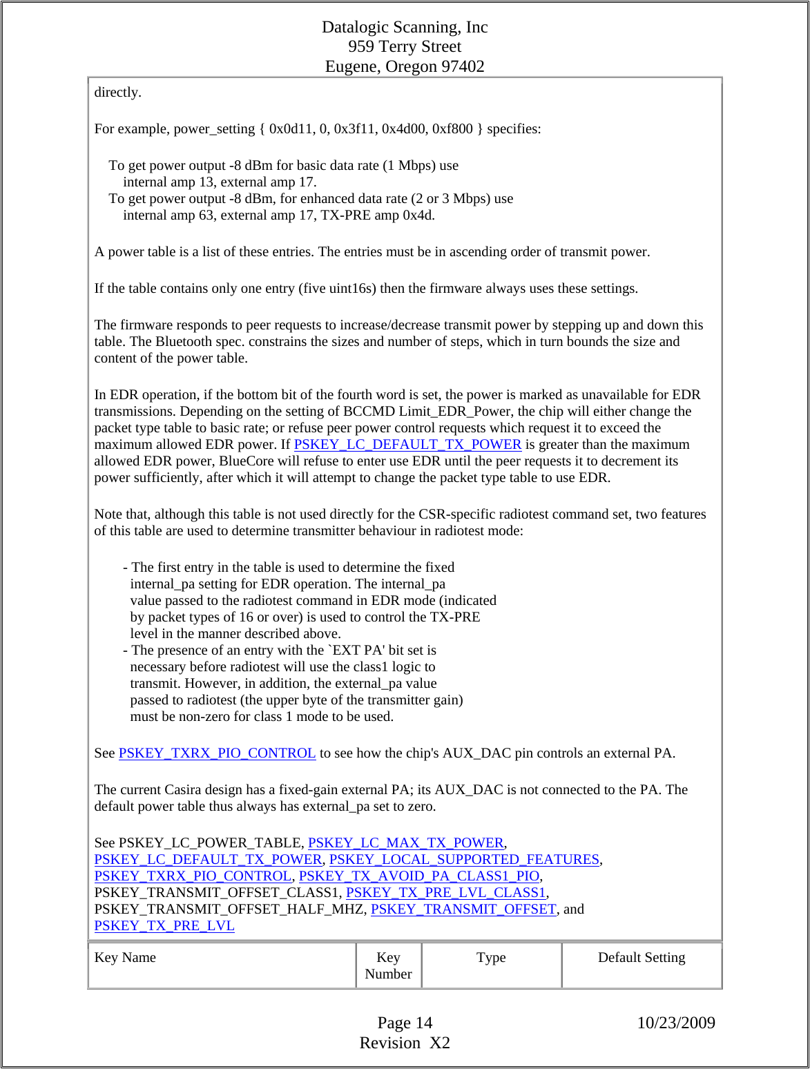
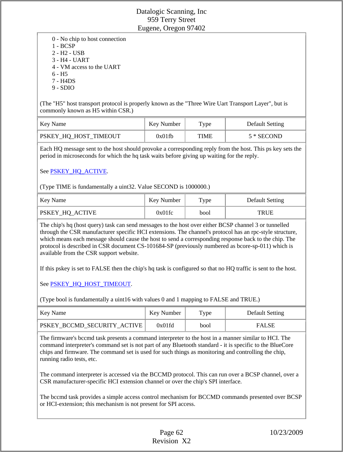
![Datalogic Scanning, Inc 959 Terry Street Eugene, Oregon 97402 Page 12 10/23/2009 Revision X2 This key can take on three values: 0: All high Priority TX packets are protected - standard setting Role Switch: Master -> High Priority Slave-> High Priority Park: Master -> High Priority Slave -> High Priority Page: High Priority Page Scan: High Priority Inquiry: High Priority Inquiry Scan:High Priority Fruitbat Test mode: High Priority LMP traffic Master or Slave: High Priority SCO: Master or Slave: High Priority Broadcast: High Priority Poll: Master: -> High Priority Start of Sniff: Master -> High Priority 1: SCO TX packets are not protected but other priority TX packets are 2: No TX packets are protected. Although some packets are not protected this key does not affect whether they are transmitted or not. Key Name Key Number Type Default Setting PSKEY_LC_ENHANCED_POWER_TABLE 0x0031 enhanced_power_setting[] {{36, 0, 0, 5, 0}, {38, 0, 0, 5, 0}, -16}, {{32, 0, 0, 4, 0}, {34, 0, 0, 4, 0}, -12}, {{34, 0, 0, 3, 0}, {36, 0, 0, 3, 0}, -8}, {{37, 0, 0, 2, 0}, {39, 0, 0, 2, 0}, -4}, {{41, 0, 0, 1, 0}, {43, 0, 0, 1, 0}, 0}, {{46, 0, 0, 0, 0}, {48, 0, 0, 0, 0}, 4} This table is used in firmware which supports the Enhanced Data Rate specification. Any values set in PSKEY_LC_POWER_TABLE are ignored; the two tables are mutually exclusive. The chip has an internal power amplifier (PA); this has a gain control. Some module designs also have an external PA; this may have a gain control. Additional, the chip has a pre-amplifier (TX-PRE) which also has a gain control. The power table stored under this pskey provides a mapping between the three PAs' gain settings and the corresponding transmit power. This table is basis of all of the firmware's transmit power control: LMP dynamic power control, PSKEY_LC_MAX_TX_POWER, PSKEY_LC_DEFAULT_TX_POWER, etc. Every module design must have an appropriate power table. The default value suits the CSR Casira hardware; this is not suitable for other module designs. The pskey's value is an array of "power_setting" types. The array's length is not fixed; typically an array is between 1 and 10 elements long. Each array element (of type "power_setting") holds seven bytes within five uint16s:](https://usermanual.wiki/Datalogic-ADC/DLBTMCX.User-manual-RF-module/User-Guide-1192966-Page-12.png)
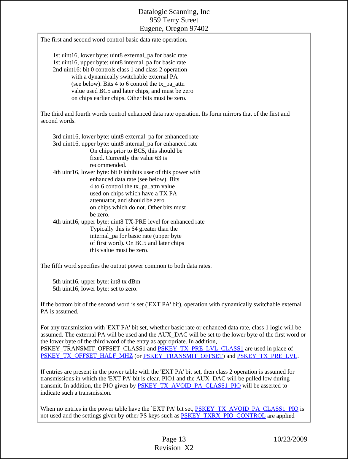
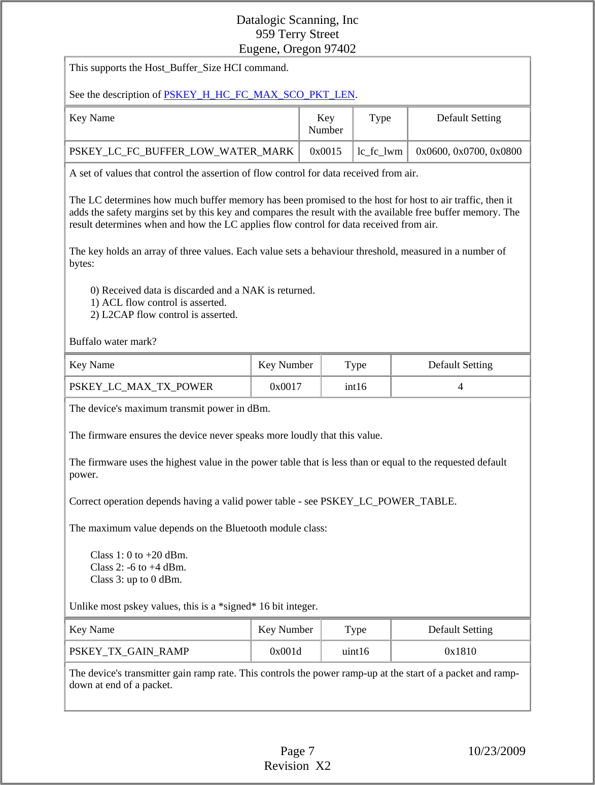
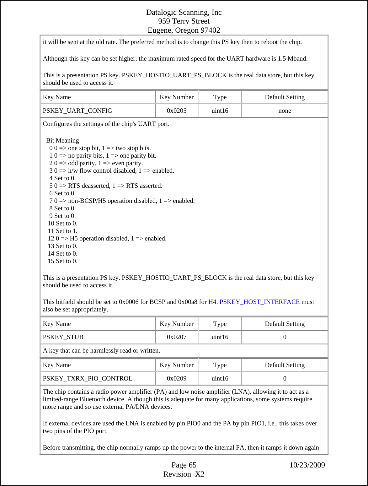
![Datalogic Scanning, Inc 959 Terry Street Eugene, Oregon 97402 Page 20 10/23/2009 Revision X2 paired with decrement peer power period. (Type TIME is fundamentally a uint32. Value SECOND is 1000000. Value MILLISECOND is 1000.) Key Name Key Number Type Default Setting PSKEY_LC_PEER_POWER_DECR_PERIOD 0x0058 TIME 1 * SECOND The period, measured in microseconds, between attempts to decrement the peer's transmit power, the same interval is used for measurements of channel quality to support LMP channel quality driven data rate messages. This pskey is paired with the respective increment peer power period. This key will have a minimum value of 100ms, how ever it will be disabled if the increment peer power period is set to 0. This means the local device will not send messages concerning peer power management. (Type TIME is fundamentally a uint32. Value SECOND is 1000000. Value MILLISECOND is 1000.) Key Name Key Number Type Default Setting PSKEY_LC_COMBO_DOT11_PULL_DIRECTION 0x005b uint16 0x0000 This key configures the input lines on some BlueCore chips associated with 802.11 coexistence interfaces. For each bit set in this PSKEY that corresponds to a coexistence input signal, the corresponding PIO will be configured with a weak pull-up, otherwise it will be left as a weak pull-down (the default). Key Name Key Number Type Default Setting PSKEY_LC_COMBO_DOT11_PERIODIC_PIO_MASK 0x005c uint16[] none A two-element array of uint16s specifying the use of PIO lines to signal the timing of very important periodic activity between BlueCore and a collocated IEEE 802.11 radio: { uint16 pio_mask, uint16 pio_invert } Bits 0 to 15 of "pio_mask" and "pio_invert" map to PIO0 to PIO15 respectively. A bit of "pio_mask" set to high enables use of the corresponding PIO pin to signal periodic activity. A bit of "pio_invert" set to high indicates that the corresponding PIO pin is active low instead of active high. PSKEY_LC_COMBO_DOT11_PERIODIC_PIO_MODE is used to control how the specified PIOs are used. Key Name Key Number Type Default Setting PSKEY_LC_COMBO_DOT11_PERIODIC_PIO_MODE 0x005d uint16 COEXISTENCE_BT_OUTPUTSet the default usage of the periodic PIO coexistence lines specified by PSKEY_LC_COMBO_DOT11_PERIODIC_PIO_MASK (if any). The pskey's acceptable values are:](https://usermanual.wiki/Datalogic-ADC/DLBTMCX.User-manual-RF-module/User-Guide-1192966-Page-20.png)
![Datalogic Scanning, Inc 959 Terry Street Eugene, Oregon 97402 Page 24 10/23/2009 Revision X2 The minimum length of an encryption key in bytes. Range 1->16. A value of 1 implies a minimum encryption key length of 8 bits, etc. (BT specification 1.1, Section 14.3.1 p159: 1<=Lmax<=16. Section 14.3.3, p161, 3rd paragraph: max key size between one and sixteen. Section 14.3.5, p166: table does not contain key of length zero.) See PSKEY_ENC_KEY_LMAX. Key Name Key Number Type Default Setting PSKEY_ENC_KEY_LMAX 0x00db uint16 16 The maximum length of an encryption key in bytes. Range 1->16. A value of 1 implies a maximum encryption key length of 8 bits, etc. (BT specification 1.1, Section 14.3.1 p159: 1<=Lmax<=16. Section 14.3.3, p161, 3rd paragraph: max key size between one and sixteen. Section 14.3.5, p166: table does not contain key of length zero.) UK Government restrictions require CSR to limit the maximum effective key length to less than 16 for some firmware builds. See PSKEY_ENC_KEY_LMIN. Key Name Key Number Type Default Setting PSKEY_LOCAL_SUPPORTED_FEATURES 0x00ef uint16[] 0xffff, 0xfe8f, 0xff9b, 0x8359 A 4 element array of uint16s holding a bitfield that describes the features supported by the local device. Coding matches the "coding of features" section in the LMP specification. The first byte of the coding of features is held in the lower byte of the first uint16, etc. The key's default value gives the firmware's capabilities. Switching a bit from 0 to 1 does not magically create a missing capability. This key configures the local LM. If a feature is marked as provided by the default value, then clearing the key's bit turns off the corresponding functionality. For example, setting the Encryption bit to zero stops the local device supporting encryption. The three "flow control lag" bits should be left at zero. The order in 1.2 of the spec is as follows. First word, low to high (X => turned on in default config; (X) => turned on if supported by hardware;) On Bit Feature X 0 3-slot packets X 1 5-slot packets X 2 Encryption X 3 Slot offset X 4 Timing accuracy](https://usermanual.wiki/Datalogic-ADC/DLBTMCX.User-manual-RF-module/User-Guide-1192966-Page-24.png)
![Datalogic Scanning, Inc 959 Terry Street Eugene, Oregon 97402 Page 25 10/23/2009 Revision X2 X 5 Master/slave switch X 6 Hold mode X 7 Sniff mode X 8 Park mode X 9 Power control requests X 10 Data rate driven by channel quality X 11 SCO link X 12 HV2 packets X 13 HV3 packets X 14 mu-law voice encoding X 15 A-law voice encoding Second word X 0 CVSD X 1 Paging scheme X 2 Power control X 3 Transparent SCO data 4 } 5 } L2CAP flow control lag (our default = 0) 6 } [1.2 features from this point] X 7 Broadcast encryption 8 Reserved (Scatter mode) (X) 9 Enhanced Data Rate ACL 2 Mbps mode (X) 10 Enhanced Data Rate ACL 3 Mbps mode X 11 Enhanced inquiry scan X 12 Interlaced inquiry scan X 13 Interlaced page scan X 14 RSSI with inquiry results (X) 15 Extended SCO link --- EV3 packets Third word (X) 0 Extended SCO link --- EV4 packets (X) 1 Extended SCO link --- EV5 packets 2 Reserved (Absence masks) X 3 AFH capable slave X 4 AFH classification slave 5 Reserved (Alias authentication) 6 Reserved (Anonymity mode) (X) 7 3-slot Enhanced Data Rate ACL packets (X) 8 5-slot Enhanced Data Rate ACL packets X 9 Sniff Subrating X 10 Pause Encryption X 11 AFH capable master X 12 AFH classification master (X) 13 Enhanced Data Rate eSCO 2 Mbps mode (X) 14 Enhanced Data Rate eSCO 3 Mbps mode (X) 15 3-slot Enhanced Data Rate eSCO packets Fourth word X 0 Extended Inquiry Response 1-2 Reserved X 3 Secure Simple Pairing X 4 Encapsulated PDU](https://usermanual.wiki/Datalogic-ADC/DLBTMCX.User-manual-RF-module/User-Guide-1192966-Page-25.png)
![Datalogic Scanning, Inc 959 Terry Street Eugene, Oregon 97402 Page 26 10/23/2009 Revision X2 5 Erroneous Data Reporting X 6 Non-flushable Packet Boundary Flag 7 Reserved X 8 Link Supervision Timeout Changed Event X 9 Inquiry Response TX Power Level 10-14 Reserved X 15 Extended features [i.e. highest bit in feature mask] Key Name Key Number Type Default Setting PSKEY_LM_USE_UNIT_KEY 0x00f0 bool FALSE Combination or unit keys can be used for authentication depending on devices' storage capacity. This key is set to TRUE if unit keys are to be used by default instead of combination keys. (Type bool is fundamentally a uint16 with values 0 and 1 mapping to FALSE and TRUE.) Key Name Key Number Type Default Setting PSKEY_HCI_NOP_DISABLE 0x00f2 bool FALSE By default the BlueCore firmware sends an HCI command_status(NOP) event to the host shortly after booting. Although this is clearly allowed by the HCI specification it is known to crash some host stacks. This pskey provides a simple workaround: if this key is TRUE then this boot-time event is not emitted. (Type bool is fundamentally a uint16 with values 0 and 1 mapping to FALSE and TRUE.) Key Name Key Number Type Default Setting PSKEY_LM_MAX_EVENT_FILTERS 0x00f4 uint8 5 Each time an event filter is added, it consumes valuable RAM resources. To limit the maximum amount of RAM event filters can take we limit the maximum number of event filters. Key Name Key Number Type Default Setting PSKEY_LM_TEST_SEND_ACCEPTED_TWICE 0x00f6 bool FALSE The Bluetooth 1.1 specification does not ensure reliability of LMP traffic in test mode, since it does not differentiate test packets (which are unreliable) from LMP packets at the baseband level. This can lead to loss of LMP messages. If this key is set to TRUE, a slave in test mode will send the LMP_Accepted reply to a test control message twice. This increases the likelihood that the message will be received by the tester. (It does not guarantee it because, since the link manager does not operate in real time, there may be test messages in between the transmissions.) (Type bool is fundamentally a uint16 with values 0 and 1 mapping to FALSE and TRUE.) Key Name Key Number Type Default Setting PSKEY_LM_MAX_PAGE_HOLD_TIME 0x00f7 uint16 0 Each time a unit pages a new device and it currently has active links, they are held for page timeout slots. If](https://usermanual.wiki/Datalogic-ADC/DLBTMCX.User-manual-RF-module/User-Guide-1192966-Page-26.png)
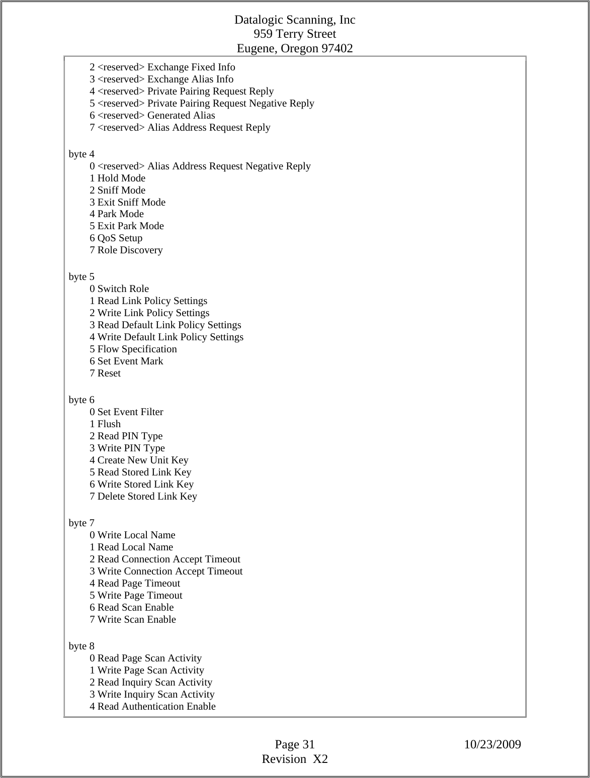
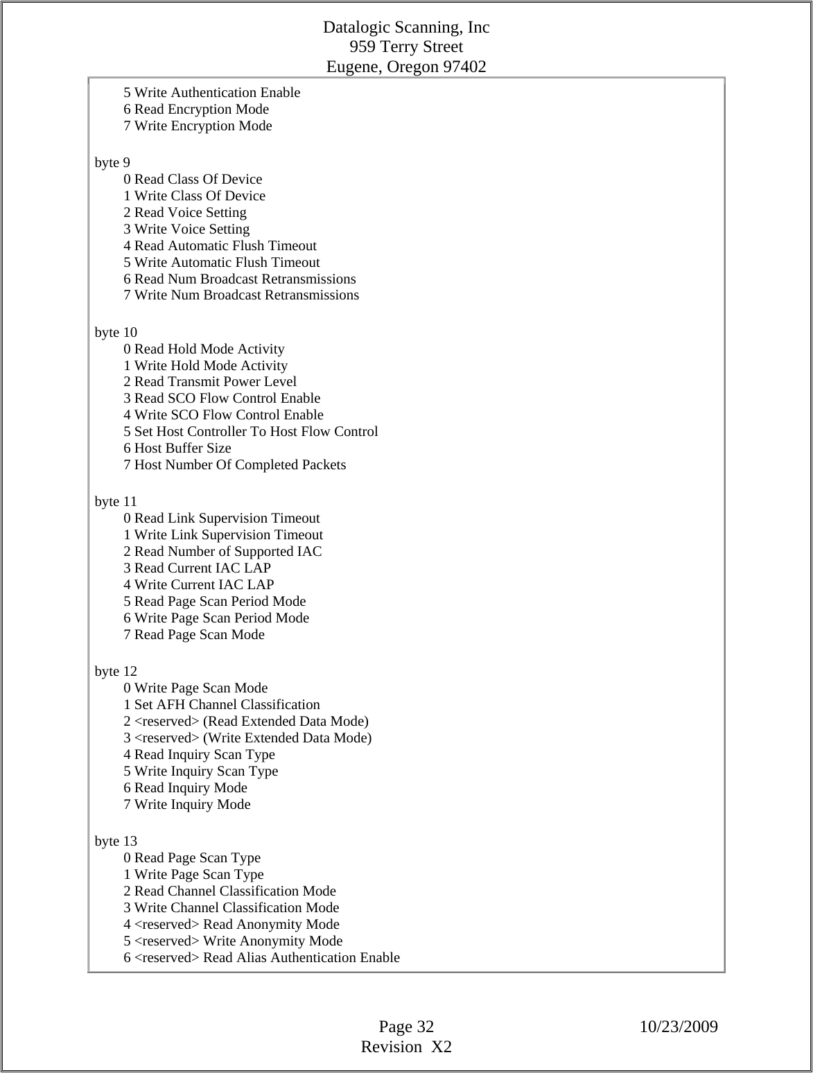
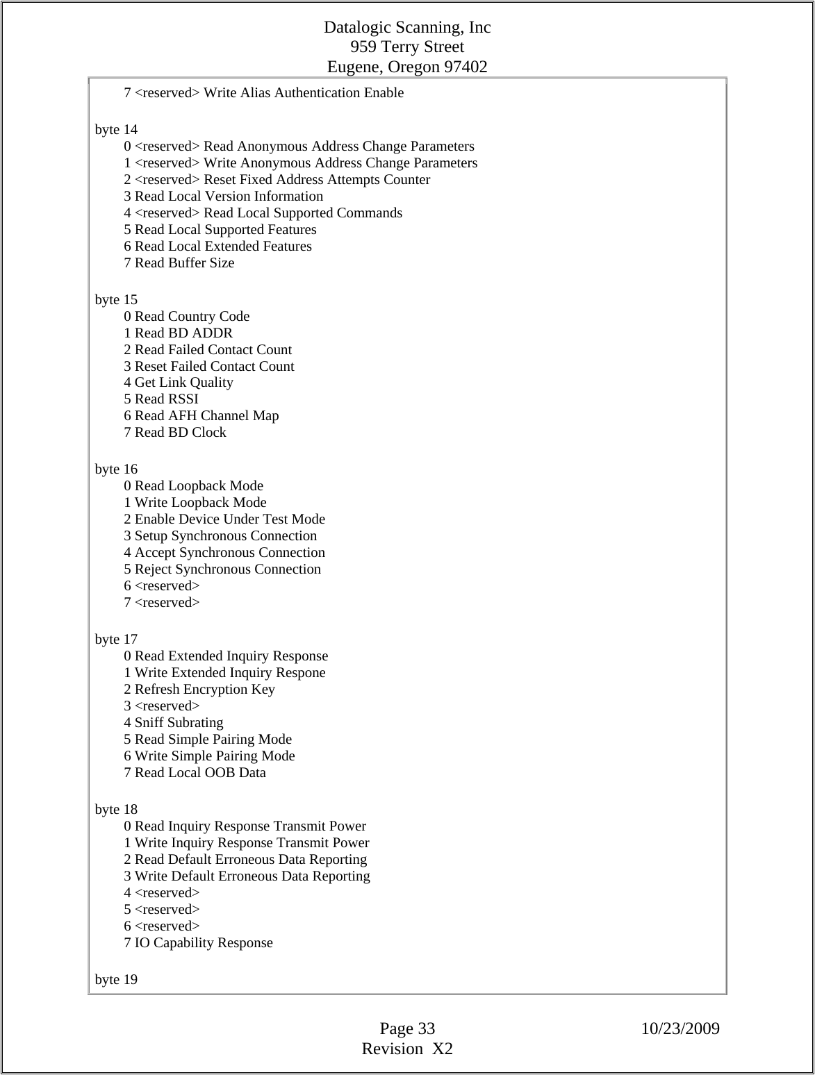
![Datalogic Scanning, Inc 959 Terry Street Eugene, Oregon 97402 Page 30 10/23/2009 Revision X2 A Bluetooth address and its corresponding link key. See description for PSKEY_PRIVATE_LINK_KEY_BD_ADDR0 Key Name Key Number Type Default Setting PSKEY_LOCAL_SUPPORTED_COMMANDS 0x0106 uint16[] 0xffff, 0x03ff, 0xfffe, 0xffff, 0xffff, 0xffff, 0x0ff3, 0xffe8, 0xf73f, 0xff83, 0x000C This is a large bitfield that describes which HCI commands are supported by the host controller. The Host can find this information out itself by trying the command, the Host Controller will then return with "Unkown HCI Command", but some Host's might prefer to try this command first. The result returned by this command does not change after the Host Controller has booted. Sometimes it is not possible for the Host Controller to perform some operations (eg. insufficent resources or not having a link of the correct type). This command will still imply that the commands are available; if the Host tries such a command the Host Controller should return a different status message than "Unkown HCI Command". byte 0 0 Inquiry 1 Inquiry Cancel 2 Periodic Inquiry Mode 3 Exit Periodic Inquiry Mode 4 Create Connection 5 Disconnect 6 Add SCO Connection 7 Cancel Create Connection byte 1 0 Accept Connection Request 1 Reject Connection Request 2 Link Key Request Reply 3 Link Key Request Negative Reply 4 PIN Code Request Reply 5 PIN Code Request Negative Reply 6 Change Connection Packet Type 7 Authentication Request byte 2 0 Set Connection Encryption 1 Change Connection Link Key 2 Master Link Key 3 Remote Name Request 4 Cancel Remote Name Request 5 Read Remote Supported Features 6 Read Remote Extended Features 7 Read Remote Version Information byte 3 0 Read Clock Offset 1 Read LMP Handle](https://usermanual.wiki/Datalogic-ADC/DLBTMCX.User-manual-RF-module/User-Guide-1192966-Page-30.png)
![Datalogic Scanning, Inc 959 Terry Street Eugene, Oregon 97402 Page 34 10/23/2009 Revision X2 0 User Confirmation Request Reply Command 1 User Confirmation Request Negative Reply Command 2 User PassKey Request Reply Command 3 User PassKey Request Negative Reply Command 4 Remote OOB Data Request Reply Command 5 Write Simple Pairing Debug Mode 6 Enhanced Flush 7 Remote OOB Data Request Negative Reply Command byte 20 0 <reserved> 1 <reserved> 2 Send Keypress Notification Command 3 IO Capability Request Negative Reply Command 4 <reserved> 5 <reserved> 6 <reserved> 7 <reserved> Key Name Key Number Type Default Setting PSKEY_LM_MAX_ABSENCE_INDEX 0x0107 uint8 1 This describes the maximum absence index that the firmware will use when assigning absence masks. This is the index number so setting this to 0 gives a maximum number of absences as 1. The spec dictates that the minimum allowed is 1 absence hence setting this value to zero gives us the legal minimum the spec allows. Key Name Key Number Type Default Setting PSKEY_DEVICE_NAME 0x0108 uint16[] 0x5343, 0x2052, 0x202d, 0x6362, 0x0036 The local device's default "user friendly" name, used by the HCI Read_Local_Name and Change_Local_Name commands and by LMP_name_req/LMP_name_res transactions. When the firmware is booted, the device's name is taken from this pskey. However, if the local host alters the local device's name, by calling the HCI Change_Local_Name command, then the new name is held in RAM. Subsequent requests to read the device's name take from the RAM store, not from this pskey. The pskey's value only becomes visble again after the firmware reboots. The BT 1.1 HCI specification requires the device's default name to be ""; an empty string. The default (psrom) value of this pskey is "CSR - bc3", or something similar, thus the psrom value does not meet the HCI specification. If this pskey is set to hold nothing, i.e., no uint16s are stored under the pskey, then the HCI default value is obtained. Over HCI and LMP the name is passed as a sequence of UTF-8 octets. Because the ps stores data in arrays of uint16s, the name is packed in this pskey, two octets per uint16. This packing is important when the ps store is small, notably where the ps is held in EEPROM. Working from start of the device's name, the first character is stored in the lower octet of the pskey's first uint16, the second character in the upper octet of the first uint16, etc. If the name is an odd number of characters then the upper octet of the last uint16 is '\0'.](https://usermanual.wiki/Datalogic-ADC/DLBTMCX.User-manual-RF-module/User-Guide-1192966-Page-34.png)
![Datalogic Scanning, Inc 959 Terry Street Eugene, Oregon 97402 Page 35 10/23/2009 Revision X2 This pskey can hold a maximum of 20 uint16s, limiting the default device name to 40 octets. The behaviour is undefined in this pskey holds more than 20 uint16s. (This size constraint does not apply to a name written via the HCI Change_Local_Name command.) The default name for BlueCore3 chips is "CSR - bc3"; when packed this becomes {0x5343, 0x2052, 0x202d, 0x6362, 0x0033}. This pskey is used from (HCI) 18.X builds. HCI 17.X and earlier builds use PSKEY_LOCAL_NAME0 -> PSKEY_LOCAL_NAME17 and PSKEY_LOCAL_NAME_LENGTH. Key Name Key Number Type Default Setting PSKEY_AFH_RSSI_THRESHOLD 0x0109 uint16 0x0800 This value controls the threshold of the entire RSSI classification algorithm. If the standard deviation of the power in the band is below this level then the device assumes that the entire band is clear and adapts its channel ratings accordingly. Key Name Key Number Type Default Setting PSKEY_LM_CASUAL_SCAN_INTERVAL 0x010a uint16 none If this key is set and is none zero, `casual scanning' is enabled. The value then gives a maximum interval in slots between page and inquiry scans. In this mode, page and inquiry scans are not necessarily performed with the frequency of the intervals set via HCI_write_inquiry_scan_activity and HCI_write_page_scan_activity. If the chip is active at any point after the interval specified over HCI since the previous scan, it will perform the scan of the appropriate type. If it does not become active within PSKEY_LM_CASUAL_SCAN_INTERVAL slots after the previous scan, it will perform the scan at that point. This is most useful on hardware starting with BlueCore3-ROM. This contains support for waking the chip from deep sleep if the host provides a clock. In this case, if the host provides a clock at any time after the normal scan interval, the chip will wake to perform the scan in synchronisation with the host. Otherwise, it will wait until PSKEY_LM_CASUAL_SCAN_INTERVAL slots have elapsed and wake anyway. For this reason this key should only be set when the host provides a clock input which goes low when the chip enters deep sleep. Otherwise there will be a significant peformance impact as the chip will be woken unnecessarily. The key is also only useful with host transports which do not use PSKEY_UART_SLEEP_TIMEOUT as the chip will stay awake for that period if woken by a host clock. This is likely to be a considerable inefficiency. On earlier hardware, the key is still usable, but casual wakeup relies on the chip being woken up for some other reason, either by the host or due to an internal timer. Casual scanning is not used in continuous page scan, since in this case the chip never becomes inactive. If casual scanning is in use, the link manager will report the scan repetition mode based on the larger of the page scan interval and the casual scan interval. Key Name Key Number Type Default Setting PSKEY_AFH_MIN_MAP_CHANGE 0x010b uint16[] 2, 4](https://usermanual.wiki/Datalogic-ADC/DLBTMCX.User-manual-RF-module/User-Guide-1192966-Page-35.png)
![Datalogic Scanning, Inc 959 Terry Street Eugene, Oregon 97402 Page 39 10/23/2009 Revision X2 When performing Simple Pairing the ECC key pair should be protected. There are 3 methods for this: - Change the private key after three failed pairing attempts or after 10 successful pairing attempts or a combination of these such that 3 successful attempts count as one failed attempt. - Verify that the received public key are on the correct curve. - Implement elliptic curve point addition and doubling using formulas that are valid only on the correct curve. When this key is set to TRUE then the first option of changing ECC keys will be enabled. If this option and PSKEY_SP_STORE_GENERATED_ECC_KEY is enabled then: - A large number of writes to PSKEY_SP_ECC_KEY may occur. - Counters are not perisistent over device reset so the key pair may not be changed at the correct time. Key Name Key Number Type Default Setting PSKEY_SP_STORE_GENERATED_ECC_KEY 0x0116 bool FALSE If this is enabled then any ECC keys generated during Simple Pairing will be written into PSKEY_SP_ECC_KEY. Key Name Key Number Type Default Setting PSKEY_SP_ECC_KEY 0x0117 uint16[] none ECC Simple Pairing Key Pair. Key Name Key Number Type Default Setting PSKEY_DFU_ATTRIBUTES 0x0136 uint8 7 The bmAttributes field of the run time DFU Functional Descriptor, as defined in Table 4.2 of USB DFU specification 1.0. The default value (7) mysteriously means "manifest tolerant, upload + download capable." This applies for the USB and "DFU over UART" (protocol name not yet allocated) protocols. Key Name Key Number Type Default Setting PSKEY_DFU_DETACH_TO 0x0137 uint16 5000 The wDetachTimeOut field of the run time DFU Functional Descriptor, as defined in Table 4.2 of USB DFU specification 1.0. The value is in milliseconds. This applies for the USB and "DFU over UART" (protocol name not yet allocated) protocols. Key Name Key Number Type Default Setting](https://usermanual.wiki/Datalogic-ADC/DLBTMCX.User-manual-RF-module/User-Guide-1192966-Page-39.png)
![Datalogic Scanning, Inc 959 Terry Street Eugene, Oregon 97402 Page 40 10/23/2009 Revision X2 PSKEY_DFU_TRANSFER_SIZE 0x0138 uint16 1023 The wTransferSize field of the run time DFU Functional Descriptor, as defined in Table 4.2 of USB DFU specification 1.0. This key applies to both the USB and "DFU over UART" (protocol name not yet allocated) protocols. The maximum permissible value for this key is 1023 for both transports. (This limit is imposed by the USB hardware). The default value (1023) is in bytes. Note that the BCSP size may be overridden (by a smaller value) at low baud rates. Key Name Key Number Type Default Setting PSKEY_DFU_ENABLE 0x0139 bool TRUE If TRUE this enables the use of dfu i.e. support for dfu will be advertised in the USB descriptors and dfu commands will be processed. Otherwise support for the protocol will not be advertised and dfu commands will be rejected. This key applies to both the USB and "DFU over UART" (protocol name not yet allocated) protocols. It is intended for use in countries such as Japan where firmware upgrades may not allowed for radio devices. (Type bool is fundamentally a uint16 with values 0 and 1 mapping to FALSE and TRUE.) Key Name Key Number Type Default Setting PSKEY_DFU_LIN_REG_ENABLE 0x013a bool FALSE Some chips have a linear regulator. On certain builds, the regsiter that controls this functionality may need to be asserted at boot time when in DFU mode. Setting this PSKEY to TRUE ensures that this occurs. Key Name Key Number Type Default Setting PSKEY_DFUENC_VMAPP_PK_MODULUS_MSB 0x015e uint16[] none This is a 32-word array containing the more significant block of the public key for DFU signing of a VM application. See PSKEY_DFUENC_VMAPP_PK_MODULUS_LSB for the other part. Key Name Key Number Type Default Setting PSKEY_DFUENC_VMAPP_PK_MODULUS_LSB 0x015f uint16[] none This is a 32-word array containing the less significant block of the public key for DFU signing of a VM application. See PSKEY_DFUENC_VMAPP_PK_MODULUS_MSB for the other part. Key Name Key Number Type Default Setting PSKEY_DFUENC_VMAPP_PK_M_DASH 0x0160 uint16 none This is a 16-bit word containing the reciprocal of the public key mod 0x10000 used in DFU signing of a VM application. Key Name Key Number Type Default Setting PSKEY_DFUENC_VMAPP_PK_R2N_MSB 0x0161 uint16[] none](https://usermanual.wiki/Datalogic-ADC/DLBTMCX.User-manual-RF-module/User-Guide-1192966-Page-40.png)
![Datalogic Scanning, Inc 959 Terry Street Eugene, Oregon 97402 Page 41 10/23/2009 Revision X2 This is a 32-word array containing the more significant block of the R2N multiplier for DFU signing of a VM application. See PSKEY_DFUENC_VMAPP_PK_R2N_LSB for the other part. Key Name Key Number Type Default Setting PSKEY_DFUENC_VMAPP_PK_R2N_LSB 0x0162 uint16[] none This is a 32-word array containing the less significant block of the R2N multiplier for DFU signing of a VM application. See PSKEY_DFUENC_VMAPP_PK_R2N_MSB for the other part. Key Name Key Number Type Default Setting PSKEY_BCSP_LM_PS_BLOCK 0x0192 BCSP_LM_PS_BLOCK 1, 0, 250 Configure the BCSP link establishment protocol. This is only used if BCSP is used over the chip's UART. The configuration uses a structure of type BCSP_LM_PS_BLOCK in which the fields are: uint16 mode 0 - disable link establishment. 1 - enable link establishment. 2 - enable passive-start link establishment. uint16 sync_retries Support for this argument has been removed. It used to set the number of sync packets emitted before the BCSP link establishment engine gave up and marked the link as dead. A value of zero meant "don't stop." The BCSP link establishment engine now always behaves as if the value is zero. uint16 tshy The Tshy value in milliseconds. This value is also used by the BCSP link establishment engine's Tconf timer. The "mode" field used to be a bool. One particular manufacturer's laptop crashes if it receives UART traffic while the machine is booting, so the "passive-start" option has been added. This causes the chip's link establishment engine to emit no messages until it receives traffic from the host. If the host pulls the same trick neither will talk to the other, so the link will never be used. Key Name Key Number Type Default Setting PSKEY_HOSTIO_FC_PS_BLOCK 0x0193 HOSTIO_FC_PS_BLOCK 250, 4, 4, FALSE Configure the host to chip hci flow control.](https://usermanual.wiki/Datalogic-ADC/DLBTMCX.User-manual-RF-module/User-Guide-1192966-Page-41.png)
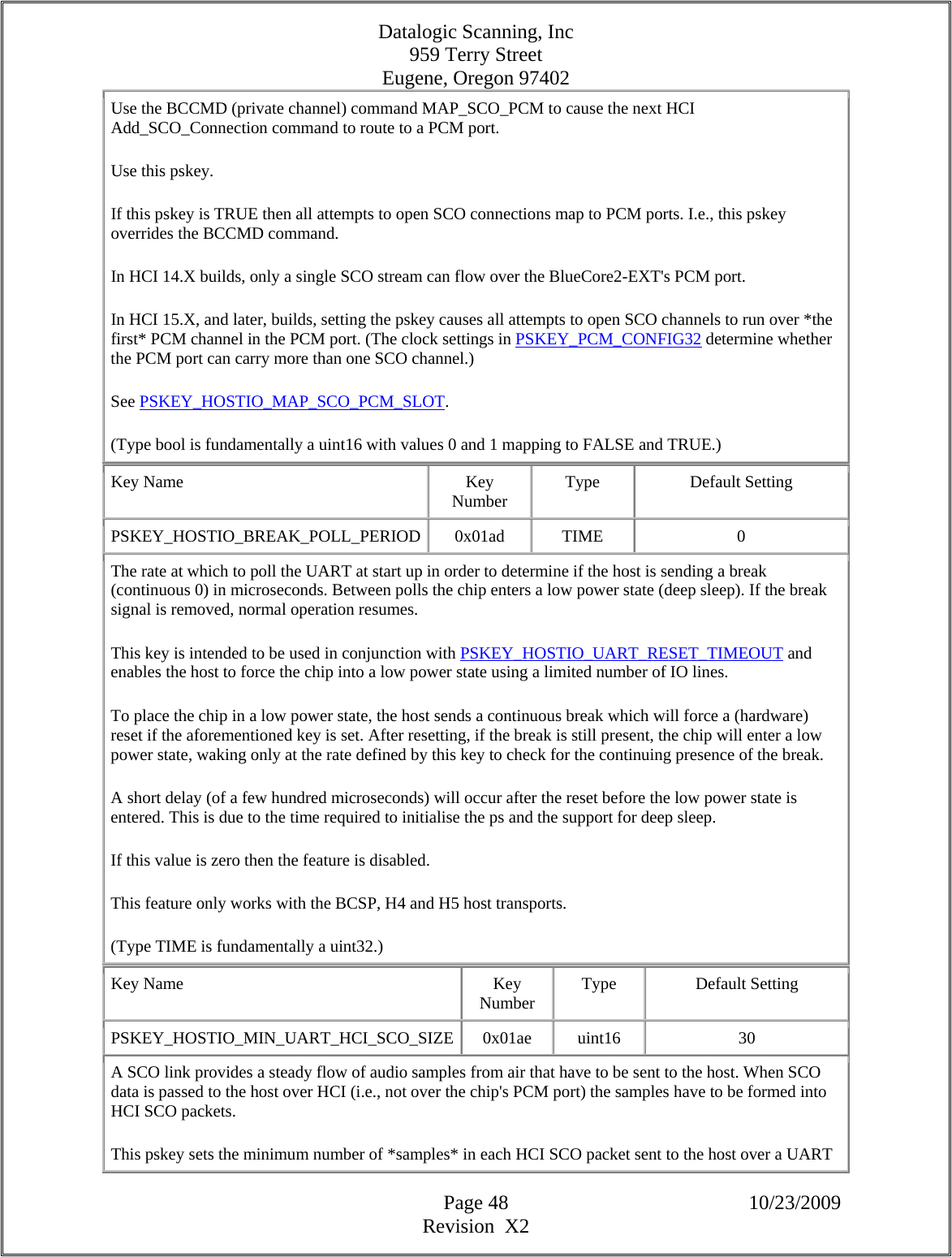
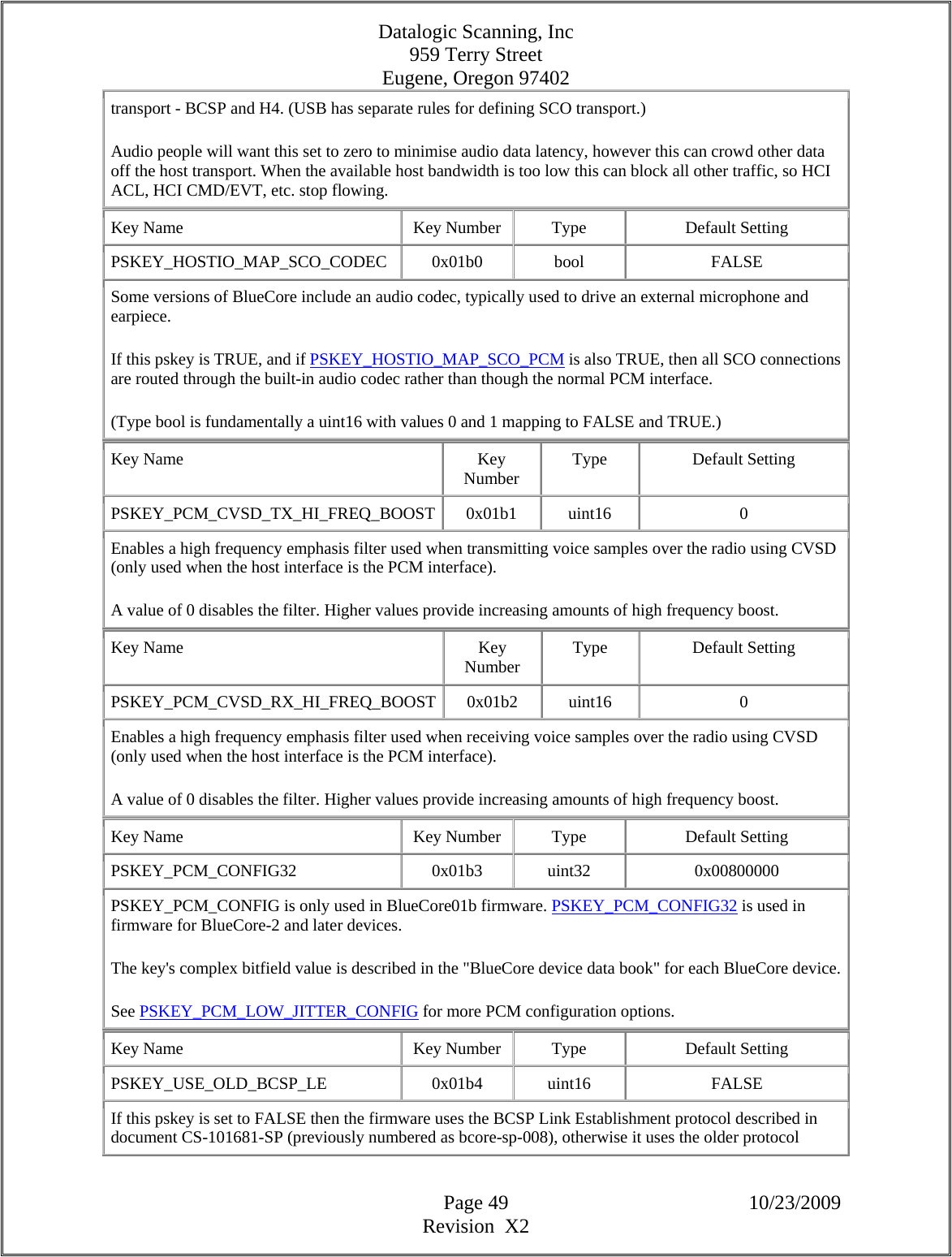
![Datalogic Scanning, Inc 959 Terry Street Eugene, Oregon 97402 Page 51 10/23/2009 Revision X2 On devices with a codec (except BlueCore2-External) this is: Bits [2:0] set the analogue gain (5 = unity gain) Bits [7:4] set the digital gain (0 = unity gain) Bits [9:8] set the sigma-delta gain (0 = nominal) On BC5-MM Bit [10] enables an extra 3dB of gain on DAC_A Bit [11] enables an extra 3dB of gain on DAC_B On BlueCore2-External, this is Bits [2:0] set the gain (7 = maximum gain) Key Name Key Number Type Default Setting PSKEY_CODEC_IN_GAIN 0x01b8 uint16 0x0008 Sets the audio input gain when using the built-in codec. On devices with a codec (except BlueCore2-External) this is: Bits [3:0] set the analogue gain (8 = optimum noise) Bits [7:4] set the digital gain (0 = unity gain) Bit [8] enables scaling down of DAC outputs On BlueCore2 External, the bits are Bits [3:0] set the gain (0xF = maximum) Key Name Key Number Type Default Setting PSKEY_CODEC_PIO 0x01b9 uint16 none Sets the Bluecore pin to drive high when the built-in codec is enabled. This is typically used to bias the microphone input. When this key is not set, no PIO pin is enabled. On older BlueCore firmware selecting PIO15 would instead use AUX_DAC. On newer firmware the value AUX_DAC should be used instead. Key Name Key Number Type Default Setting PSKEY_PCM_LOW_JITTER_CONFIG 0x01ba uint32 0x00000000 Additional PCM configuration to support master mode with much reduced jitter on the clock. This is required to support certain external codec chips. Only useful for chips starting with BlueCore2-ROM. See PSKEY_PCM_CONFIG32 for more PCM configuration options. Key Name Key Number Type Default Setting PSKEY_HOSTIO_SCO_PCM_THRESHOLDS 0x01bb uint16[] 8, 20 Sets the upper and lower thresholds for the buffers used to hold SCO data flowing between air and the PCM port. The thresholds are checked just before a packet is received from air and just after a packet is sent to air. If the data pending in the buffer exceeds the upper threshold when the level is checked, a sample is deleted from the buffer.If the pending data in the buffer drops below the lower threshold, a sample is inserted into](https://usermanual.wiki/Datalogic-ADC/DLBTMCX.User-manual-RF-module/User-Guide-1192966-Page-51.png)
![Datalogic Scanning, Inc 959 Terry Street Eugene, Oregon 97402 Page 52 10/23/2009 Revision X2 the buffer. The thresholds are held as a uint16[2]. The first value gives the lower threshold and the second value gives the upper threshold. This PS key has no effect on some versions of firmware. Key Name Key Number Type Default Setting PSKEY_HOSTIO_SCO_HCI_THRESHOLDS 0x01bc uint16[] 10, 80 Sets the upper and lower thresholds for the buffers used to hold SCO data flowing between air and the HCI. The thresholds are checked just before a packet is received from air and just after a packet is sent to air. When the thresholds are exceeded, the firmware will insert or delete single samples or groups of samples to bring the amount of data pending in the buffer into range. The exact behaviour depends on whether the SCO data is in transparent format and which host transport is in use. The thresholds are held as a uint16[2]. The first value gives the lower threshold and the second value gives the upper threshold. This PS key has no effect on some versions of firmware. Key Name Key Number Type Default Setting PSKEY_HOSTIO_MAP_SCO_PCM_SLOT 0x01bd uint16 0 When the pskey PSKEY_HOSTIO_MAP_SCO_PCM is TRUE, the first SCO channel opened is routed over the chip's PCM port. While this SCO channel is in place, all subsequent attempts to open extra SCO channels fail. The SCO channel is routed over the PCM timing frame slot defined by this pskey. This pskey's default value, zero, routes to "the first" PCM slot. The number of slots in the PCM port's timing frame depends on the value of PSKEY_PCM_CONFIG32; there's no point in setting PSKEY_HOSTIO_MAP_SCO_PCM_SLOT to 3, asking for SCO data to travel over the 4th slot in the PCM frame if the PCM channel's clock rate only supports a single slot per frame. (This pskey is available only in builds for BlueCore-2 and later chips. Functionality equivalent to this pskey is available in BlueCore01b builds using a bit field in PSKEY_PCM_CONFIG, a pskey absent from builds for BlueCore-2 and later chips.) Key Name Key Number Type Default Setting PSKEY_UART_BAUDRATE 0x01be uint16 0x0000 The UART's (initial) Baud rate in builds from HCI 18.X. (This PS key's name is similar to PSKEY_UART_BAUD_RATE, used in firmware builds before HCI 18.X.) A value of 0 has a special meaning which is to enable automatic detection of the UART baud rate from data sent by the host to the BlueCore following a chip reset. Note that this is designed for use with ROM](https://usermanual.wiki/Datalogic-ADC/DLBTMCX.User-manual-RF-module/User-Guide-1192966-Page-52.png)
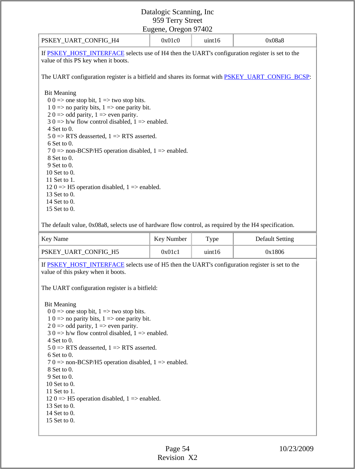
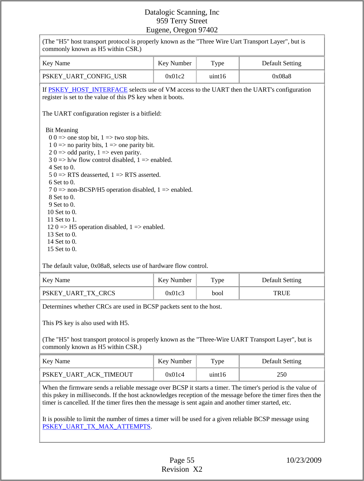
![Datalogic Scanning, Inc 959 Terry Street Eugene, Oregon 97402 Page 56 10/23/2009 Revision X2 This pskey is also used with H5. (The "H5" host transport protocol is properly known as the "Three Wire Uart Transport Layer", but is commonly known as H5 within CSR.) Key Name Key Number Type Default Setting PSKEY_UART_TX_MAX_ATTEMPTS 0x01c5 uint16 0 The description of PSKEY_UART_ACK_TIMEOUT outlines BCSP's mechanism to retransmit reliable messages to the host until acknowledged. The value of PSKEY_UART_TX_MAX_ATTEMPTS sets a limit on the number of times the send/timeout cycle will be attempted. Current (HCI 18.X) firmware will panic (and normally reboot) if this limit is reached. Messages are sent indefinitely if this pskey is set to zero, i.e., the value zero is treated as infinity. This pskey is also used with H5. (The "H5" host transport protocol is properly known as the "Three Wire Uart Transport Layer", but is commonly known as H5 within CSR.) Key Name Key Number Type Default Setting PSKEY_UART_TX_WINDOW_SIZE 0x01c6 uint16 4 The size of the sliding window used by BCSP. When the baseband sends a reliable BCSP message to the host then the host is required to acknowledge its reception. (If it is not acknowledged within a certain period the message is sent again.) The baseband will send several packets to the host before waiting for the first of the bunch to be acknowledged. The maximum number of sent packets that can be unacknowledged at any time is set by this pskey. This pskey is also used with the firmware's H5 driver. (The "H5" host transport protocol is properly known as the "Three Wire Uart Transport Layer", but is commonly known as H5 within CSR.) Key Name Key Number Type Default Setting PSKEY_UART_HOST_WAKE 0x01c7 uint16[] 4, 500, 10, 0 Configure the use of a wakeup signal by the BlueCore to wake the peer UART device from a low power state. The wakeup signal, which may be either a UART break condition or a pulse on a PIO line, is specified via a separate PS key, PSKEY_UART_HOST_WAKE_SIGNAL. If this PS key's mechanism is turned on, the firmware judges when the peer may have entered its deep sleep state based on timers, and the local device can be set to emit a wakeup signal before sending data to the peer. Normally the length of the break condition is set to be sufficient to allow the peer to come fully awake as the local device will normally send a message to the peer afterwards.](https://usermanual.wiki/Datalogic-ADC/DLBTMCX.User-manual-RF-module/User-Guide-1192966-Page-56.png)
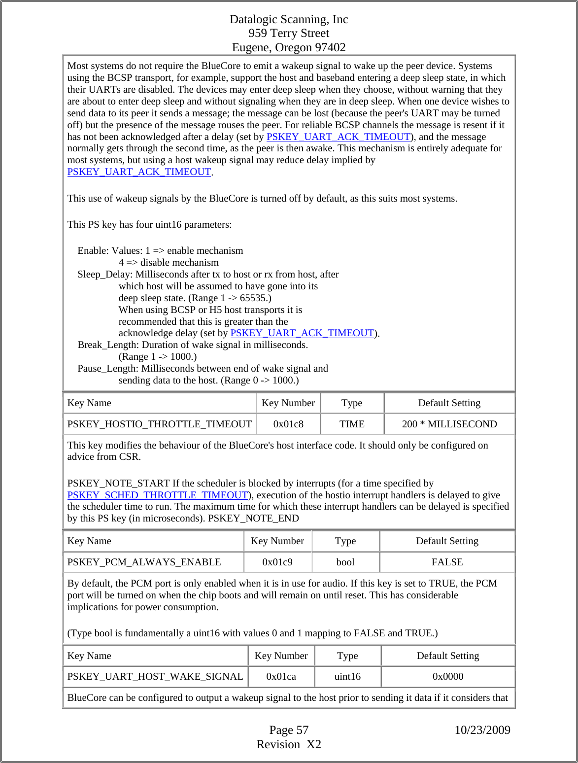
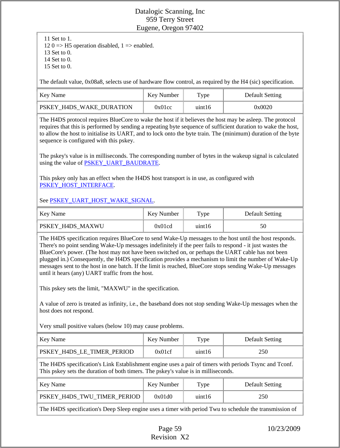
![Datalogic Scanning, Inc 959 Terry Street Eugene, Oregon 97402 Page 58 10/23/2009 Revision X2 the host may be in a low power state. PSKEY_UART_HOST_WAKE enables this wakeup signalling and specifies the various timers required. PSKEY_UART_HOST_WAKE_SIGNAL is used to specify the wakeup signal to use: this is a UART break signal, a pulse on a PIO line or, for the H4DS transport only, a repeated byte sequence. This PS key's value is a bitfield, allocated as: bits 0 to 3: Host Wake Mechanism. Values: 0 - repeated byte sequence 1 - positive pulse on PIO 2 - negative pulse on PIO 3 - UART BREAK condition bits 4 to 7: PIO pin selection. Value selects PIO pin. If the Host Wake Mechanism is 0x00, and the host transport is H4DS, BlueCore will send a repeated byte sequence. The duration of the byte train is specified by PSKEY_H4DS_WAKE_DURATION. The byte sequence has been chosen to work well with BlueCore's Baud rate detection capability. If the host transport is BCSP or H5 a break condition is signalled by the UART. The duration of the break signal is specified by PSKEY_UART_HOST_WAKE. If the Host Wake Mechanism is 0x01 then a positive pulse is signalled on the PIO pin selected by bits 4->7. (Value 0x0 in bits 4->7 selects PIO[0], value 0x01 selects PIO[1], etc.). The duration of the pulse is specified by PSKEY_H4DS_WAKE_DURATION for the H4DS transport and by PSKEY_UART_HOST_WAKE for all other host transports. If the Host Wake Mechanism is 0x02 then a negative pulse is signalled on the PIO pin selected by bits 4->7. The duration of the pulse is specified by PSKEY_H4DS_WAKE_DURATION for the H4DS transport, and by PSKEY_UART_HOST_WAKE for all other host transports. If the Host Wake Mechanism is 0x03 then a break condition is signalled by the UART. The duration of the break signal is specified by PSKEY_H4DS_WAKE_DURATION for the H4DS transport, and by PSKEY_UART_HOST_WAKE for all other host transports. Key Name Key Number Type Default Setting PSKEY_UART_CONFIG_H4DS 0x01cb uint16 0x08a8 If PSKEY_HOST_INTERFACE selects use of H4DS then the UART's configuration register is set to the value of this PS key when the system boots. The UART configuration register is a bitfield: Bit Meaning 0 0 => one stop bit, 1 => two stop bits. 1 0 => no parity bits, 1 => one parity bit. 2 0 => odd parity, 1 => even parity. 3 0 => h/w flow control disabled, 1 => enabled. 4 Set to 0. 5 0 => RTS deasserted, 1 => RTS asserted. 6 Set to 0. 7 0 => non-BCSP/H5 operation disabled, 1 => enabled. 8 Set to 0. 9 Set to 0. 10 Set to 0.](https://usermanual.wiki/Datalogic-ADC/DLBTMCX.User-manual-RF-module/User-Guide-1192966-Page-58.png)
![Datalogic Scanning, Inc 959 Terry Street Eugene, Oregon 97402 Page 63 10/23/2009 Revision X2 This pskey enables the security mechanism. When a BlueCore module is freshly manufactured this bool flag is set FALSE. The host may then read and write all ps values and can run all of the BCCMD commands. This allows the manufacturer to configure the Bluetooth module. When the configuration is complete the manufacturer sets this pskey to TRUE. This enables the ps and bccmd access controls. Once set TRUE this key cannot be set back to FALSE via BCSP running over BCSP or the HCI extension channel. Setting security active is thus normally a one-way operation. (Type bool is fundamentally a uint16 with values 0 and 1 mapping to FALSE and TRUE.) Key Name Key Number Type Default Setting PSKEY_ANA_FREQ 0x01fe uint16 none Configures the BlueCore hardware to work with a particular reference clock frequency. For chips prior to BlueCore2-ROM the default, 4, configures the chip to use a 16 MHz reference. The value defines a reference frequency of n*250 kHz where n is an integer, but there is a pseudo-random mapping from n to the required value. This is covered in supporting documentation. For BlueCore2-ROM and subsequent chips, the value defines the reference frequency in units of 1 kHz. The default value, 26000, configures the chip to use a 26 MHz reference. If the key is absent or the value is zero, the chip will attempt to pick a frequency; this cannot be relied upon to be the correct frequency, so the radio will not be usable. The automatic clock frequency detection mechanism is likely to be most useful in ROM parts, and is further described in document CS-101436-ME (previously numbered as bcore-me-014) which is available from the CSR support website. See also the description of PSKEY_ANA_FTRIM. Key Name Key Number Type Default Setting PSKEY_PIO_PROTECT_MASK 0x0202 uint16 0 Each BlueCore chip contains a PIO port that may, under BCCMD or VM control, be used as a general input / output port. However, various optional hardware and software configurations require the use of certain PIO pins for their own needs, e.g., an optional external PA/LNA block may be driven using PIO pins 0 and 1. This pskey prevents applications from changing PIO pins that are required for lower level functions. This blocking action applies to host-based applications requesting PIO changes via BCCMD and to VM applications running on the chip. Some of the lower level functions automatically prevent the application from changing the state of PIOs being used by the function by overriding the value of the relevant bits in this pskey. This includes the PIOs related to PSKEY_TXRX_PIO_CONTROL, PSKEY_USB_PIO_VBUS, PSKEY_USB_PIO_DETACH, PSKEY_USB_PIO_PULLUP, PSKEY_USB_PIO_WAKEUP and PSKEY_USB_PIO_RESUME (so, for instance, if PSKEY_USB_PIO_DETACH claims the use of PIO[5] then this PIO cannot be changed by application code no matter what the value of PSKEY_PIO_PROTECT_MASK is).](https://usermanual.wiki/Datalogic-ADC/DLBTMCX.User-manual-RF-module/User-Guide-1192966-Page-63.png)
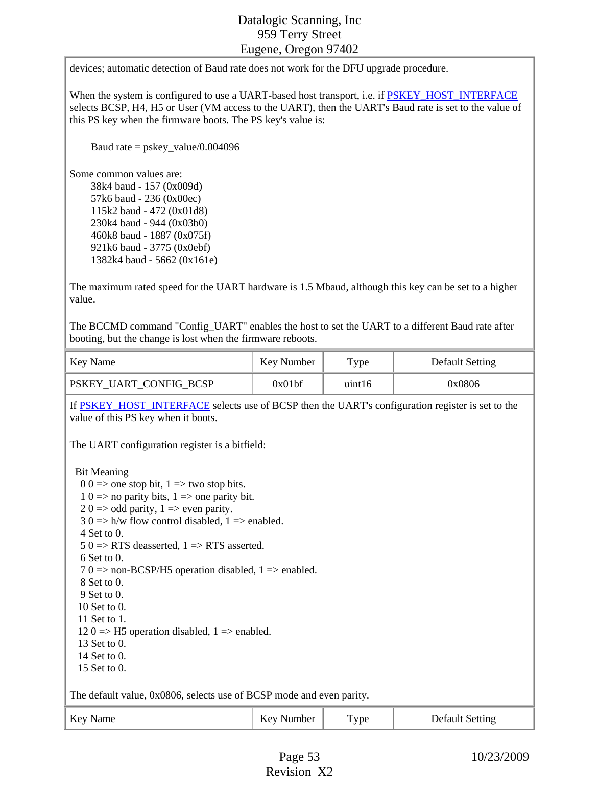
![Datalogic Scanning, Inc 959 Terry Street Eugene, Oregon 97402 Page 64 10/23/2009 Revision X2 Bits 0 to 7 of this uint16 pskey map to PIO0 to PIO7 respectively. If a bit of the pskey's value is set high then application code cannot change the value of the corresponding PIO port pin. NOTE: On the current Casira motherboard, PIO2 is connected to USB+ via a 1k5 resistor. The USB+ pin doubles as the UART RTS line on BlueCore, so care must be taken if an application uses PIO2. Key Name Key Number Type Default Setting PSKEY_PMALLOC_SIZES 0x0203 uint16[] The pmalloc pool memory manager is used throughout the firmware. The way in which its raw RAM block is fragmented is specified by this pskey. The value is an array of pairs of uint16s: {uint16 el_size, uint16 n_elements}. Each pair describes a pool containing n_elements each of size el_size. The array must be terminated with {0, 0}. The total number of pools must not exceed MAX_POOLS, defined in pmalloc.h. (At the time of writing this comment the value is 20.) The size of the raw RAM block is TOTAL_POOL_SIZE uint16s, defined in xpmalloc.c, so this depends on the firmware build. How this is carved up is a complex issue - the bulk of the block will normally be fragmented according to the value of this pskey, but the start of the block is used to hold pool management information - pool control blocks. The size of this management information depends on the number of pools and whether pmalloc debugging information is being maintained - at the time of writing this comment it takes 7 uint16s per pool. This may typically take 10% of the total, so very crudely, sum(el_size*n_elements) <= (0.9 * TOTAL_POOL_SIZE). If the definition of how the memory should be used exceeds the capacity of TOTAL_POOL_SIZE then the allocation is simply truncated. Typically the last pool in the array ends up with fewer elements than requested. The array does not have to be in size order, so it may make sense for the last element in the list to define a pool whose size may be flexible. Also the memory is most efficiently used if this last pool has a small el_size. The pskey's default value is taken from C #include file ps_pools.h. The include file is derived from file pools.cfg during compilation. Key Name Key Number Type Default Setting PSKEY_UART_BAUD_RATE 0x0204 uint16 none The UART's (initial) Baud rate in builds before HCI 18.X. (This PS key's name is similar to PSKEY_UART_BAUDRATE, used in builds from HCI 18.X.) Set the chip's UART baud rate at boot time to: baud_rate = ps_value/0.004096 Some common baud_rate values: 38k4 baud - 157 (0x009d) 115k2 baud - 472 (0x01d8) A BCCMD command allows the baud rate to be changed instantly but this presents the problem that if the command succeeds then notification of the command's behaviour will be sent at the new rate, and if it fails](https://usermanual.wiki/Datalogic-ADC/DLBTMCX.User-manual-RF-module/User-Guide-1192966-Page-64.png)
![Datalogic Scanning, Inc 959 Terry Street Eugene, Oregon 97402 Page 68 10/23/2009 Revision X2 Internal PA gain setting at which to perform IQ trim auto-calibration. If the pskey value is higher than the maximum level in the power table (see PSKEY_LC_POWER_TABLE) the firmware will silently limit it to the power table's maximum internal PA setting. Bits [11:8] set the transmitter pre-amplifier gain while bits [7:0] set the maximum allowed power amplifier gain (but a lower value may be used). Key Name Key Number Type Default Setting PSKEY_TX_OFFSET_HALF_MHZ 0x0217 int16 -2 Frequency offset used for transmit, in units of 500 kHz. For BC5+ it controls only the basic rate Class 2 transmit offset This key should only be changed on advice from CSR. Key Name Key Number Type Default Setting PSKEY_GBL_MISC_ENABLES 0x0221 uint16 0x81c This allows settings for various bits in the chip's $GBL_MISC_ENABLES register to be selected. It allows the MISC_XAP_SUSPEND_ON_RX_EN, MISC_FAST_FLASH_EN, MISC_TRISTATE_DRIVE_EN, MISC_SPI_STOP_OUT_EN and MISC_EXT_RAM_EN bits (bits 0, 2, 3, 4 and 7 respectively) to be selected. The bits are written as the value of the corresponding bits in this pskey; the other bits in this pskey's value are ignored. The default setting does not suspend the XAP on Rx, enables the tristate drive and SPI stop output signal, and does not enable external RAM. The default setting for FAST_FLASH_EN depends on the firmware version. On chips up to and including BlueCore4, MISC_FAST_FLASH_EN controls whether the chip generates wait states for Flash access. The correct setting depends on the Flash device in use: - Setting this bit to 0 requires Flash with access speed of 90ns or faster. This is the safe setting. - Setting this bit to 1 requires Flash with access speed of 45ns or faster ("fast flash"). If your Flash meets this specification, setting this bit may allow faster execution and hence power savings. If "fast flash" mode is enabled incorrectly, firmware may not execute correctly. The FAST_FLASH_EN bit is ignored from BlueCore5 onwards (PSKEY_PROG_WAIT_STATES is the nearest equivalent). It is also ignored when running from ROM on some previous devices. (Setting 0x08 disables the SPI MISO line.) This is for CSR internal use only. Don't play with it unless you know what it does. Key Name Key Number Type Default Setting PSKEY_UART_SLEEP_TIMEOUT 0x0222 uint16 1000](https://usermanual.wiki/Datalogic-ADC/DLBTMCX.User-manual-RF-module/User-Guide-1192966-Page-68.png)
![Datalogic Scanning, Inc 959 Terry Street Eugene, Oregon 97402 Page 73 10/23/2009 Revision X2 reference is required (for instance, when the BlueCore is in deep sleep). If set to 0, no PIO is used as a clock request. If set to 1, PIO[6] is active when an external clock reference is required, and is inactive otherwise. If set to 2, PIO[2] is active when an external clock reference is required, and is inactive otherwise. If set to 3, PIO[2] is active when an external clock reference is required or if PIO[3] is high, and is inactive when a clock reference is not required and PIO[3] is low. Values of 2 and 3 are only useful for versions of the BlueCore hardware starting with BlueCore2-ROM. In the default configuration, a PIO is held high when active and held low when inactive. In versions of BlueCore from BlueCore3-ROM, this behaviour can be altered by setting PSKEY_CLOCK_REQUEST_FEATURES. Key Name Key Number Type Default Setting PSKEY_RX_MIN_ATTEN 0x0249 uint16 0 Minimum allowed attenuation for receiver apart from channels 29,30,31,61,62,63. This can be used to improve C/I performance and to improve consistency of receiver sensitivity over frequency range. Key Name Key Number Type Default Setting PSKEY_XTAL_TARGET_AMPLITUDE 0x024b uint8 204 This sets the target crystal oscillation amplitude as determined by the device's internal circuitry. This is not as will be measured using external instruments. Pre-BC5 the pskey is used to set an absolute internal oscillation amplitude. For BC5 the pskey sets a % of the maximum measured internal amplitude, it is a relative internal level. Note: As a rule, the default value issued by CSR will not need to be changed. The crystal bias level is chosen such that the oscillation amplitude is as close as possible to the target. This is done by gradually decreasing the crystal bias level from its maximum until the target amplitude is reached. The target amplitude is treated as a minimum; as long as it is achievable, the firmware will use a crystal bias that produces at least the requested amplitude. It was originally possible to set the crystal bias level directly but that control has been superseded by this improved "set and measure" approach. This provides correct operation with some variance in crystal parameters and also tracks over changes in temperature, it is not intended as a level control mechanism per-se. A module designer may wish to test the effect of changing the configured target amplitude across a representative sample of modules and adjust the production target amplitude accordingly. This assessment of level should be made by observing the correct operation of the unit rather than trying to measure the amplitude directly. Typically, setting a value larger than the correct one will lead to a stable crystal that draws an unnecessarily large current. Setting a value smaller than the correct one can lead to the system clock being unstable and it may even stop.](https://usermanual.wiki/Datalogic-ADC/DLBTMCX.User-manual-RF-module/User-Guide-1192966-Page-73.png)
![Datalogic Scanning, Inc 959 Terry Street Eugene, Oregon 97402 Page 75 10/23/2009 Revision X2 retransmissions to wake the chip. Usually, therefore, this key will be used in combination with PSKEY_DEEP_SLEEP_WAKE_CTS. (Type bool is fundamentally a uint16 with values 0 and 1 mapping to FALSE and TRUE.) Key Name Key Number Type Default Setting PSKEY_RF_RESONANCE_TRIM 0x0254 uint16 0x34ff Sets the frequency trim for the IQ and LNA resonant circuits. (This is for CSR internal use only. If you don't know what it's for, don't play with it.) Key Name Key Number Type Default Setting PSKEY_DEEP_SLEEP_PIO_WAKE 0x0255 uint16 16 The number of a PIO line, 0 to 15, which will cause the chip to wake from deep sleep. This use does not preclude the use of the same PIO line as an ordinary input. However, a PIO which is usually configured as an output may not be used. If the setting is out of range, no PIO line will be used. The wake-up is triggered by the level of the line being held high for at least 1 millisecond, not by the rising or falling edge. If the chip notices it has been woken, and it is configured to use the UART, it will remain out of deep sleep for at least the period given by PSKEY_UART_SLEEP_TIMEOUT. This is because it cannot distinguish wakeups from the two sources. Otherwise, the chip may return to deep sleep as soon as there is no task to be performed. If the VM is configured to use a PIO line as an interrupt source, the chip will automatically be woken from deep sleep on that line, so this key is not usually required. It may still be used; however, the chip may generate interrupts on the PIO line set by this key, since it does not discriminate between individual PIO lines. Key Name Key Number Type Default Setting PSKEY_MODULE_ID 0x0259 uint32 0 A serial number for the module. This number may be allocated by the module manufacturer to track production, etc. This value is not used by any on-chip code and is for manufacturer information only. The firmware makes no use of this key's value. Key Name Key Number Type Default Setting PSKEY_MODULE_DESIGN 0x025a uint16 0 An identifier of the Bluetooth module design. This is allocated by the module manufacturer, so the combination of this key and PSKEY_MODULE_MANUFACTURER should be enough to specify a hardware module design. This value will normally be independent of firmware identifiers which are used to distinguish various builds of the module's software. The firmware makes no use of this key's value. Key Name Key Number Type Default Setting PSKEY_MODULE_SECURITY_CODE 0x025c uint16[] none](https://usermanual.wiki/Datalogic-ADC/DLBTMCX.User-manual-RF-module/User-Guide-1192966-Page-75.png)
![Datalogic Scanning, Inc 959 Terry Street Eugene, Oregon 97402 Page 76 10/23/2009 Revision X2 When the module is intended to be used with certain host-side applications or stacks, this key is set to an encrypted value. The host-side application may subsequently check the value of this key to determine whether or not it is licensed to run with the module. Key Name Key Number Type Default Setting PSKEY_VM_DISABLE 0x025d bool FALSE If TRUE, the VM will not be started when the chip boots. If FALSE, VM operation is normal. (Type bool is fundamentally a uint16 with values 0 and 1 mapping to FALSE and TRUE.) Key Name Key Number Type Default Setting PSKEY_MOD_MANUF0 0x025e uint16[] none Keys PSKEY_MOD_MANUF0 to PSKEY_MOD_MANUF9 are for use by module manufactuers. The firmware makes no use of these pskeys' contents. Keys PSKEY_MOD_MANUF0 to PSKEY_MOD_MANUF4 are protected against DFU; they are never included in uploads, and are ignored in downloads. This makes them suitable for storing module specific or sensitive information; use keys in the range PSKEY_MOD_MANUF5 to PSKEY_MOD_MANUF9 if such protection is not required. Key Name Key Number Type Default Setting PSKEY_MOD_MANUF1 0x025f uint16[] none See the description of PSKEY_MOD_MANUF0. Key Name Key Number Type Default Setting PSKEY_MOD_MANUF2 0x0260 uint16[] none See the description of PSKEY_MOD_MANUF0. Key Name Key Number Type Default Setting PSKEY_MOD_MANUF3 0x0261 uint16[] none See the description of PSKEY_MOD_MANUF0. Key Name Key Number Type Default Setting PSKEY_MOD_MANUF4 0x0262 uint16[] none See the description of PSKEY_MOD_MANUF0. Key Name Key Number Type Default Setting PSKEY_MOD_MANUF5 0x0263 uint16[] none See the description of PSKEY_MOD_MANUF0. Key Name Key Number Type Default Setting](https://usermanual.wiki/Datalogic-ADC/DLBTMCX.User-manual-RF-module/User-Guide-1192966-Page-76.png)
![Datalogic Scanning, Inc 959 Terry Street Eugene, Oregon 97402 Page 77 10/23/2009 Revision X2 PSKEY_MOD_MANUF6 0x0264 uint16[] none See the description of PSKEY_MOD_MANUF0. Key Name Key Number Type Default Setting PSKEY_MOD_MANUF7 0x0265 uint16[] none See the description of PSKEY_MOD_MANUF0. Key Name Key Number Type Default Setting PSKEY_MOD_MANUF8 0x0266 uint16[] none See the description of PSKEY_MOD_MANUF0. Key Name Key Number Type Default Setting PSKEY_MOD_MANUF9 0x0267 uint16[] none See the description of PSKEY_MOD_MANUF0. Key Name Key Number Type Default Setting PSKEY_DUT_VM_DISABLE 0x0268 bool TRUE If TRUE, the VM will be disabled when the chip enters radiotest modes (either Bluetooth or CSR-specific test modes). If FALSE, the VM continues operating. It is recommended this only be set to FALSE if the VM application is being used to control test mode; this is necessary, for example, in configurations where no host interface is present. (Type bool is fundamentally a uint16 with values 0 and 1 mapping to FALSE and TRUE.) Key Name Key Number Type Default Setting PSKEY_USR0 0x028a uint16[] none Keys PSKEY_USR0 to PSKEY_USR49 are for use by host and on-chip application- specific code to allocate as it chooses. PSKEY_USR0 to PSKEY_USR24 may only be changed by DFU by placing them in the application protected section of the file and signing them with the application private key. These pskeys are never incldued in DFU files uploaded from a BlueCore. This makes them suitable for storing module specific or sensitive information; use keys in the range PSKEY_USR25 to PSKEY_USR49 if such protection is not required. Key Name Key Number Type Default Setting PSKEY_USR1 0x028b uint16[] none See the description of PSKEY_USR0. Key Name Key Number Type Default Setting PSKEY_USR2 0x028c uint16[] none See the description of PSKEY_USR0.](https://usermanual.wiki/Datalogic-ADC/DLBTMCX.User-manual-RF-module/User-Guide-1192966-Page-77.png)
![Datalogic Scanning, Inc 959 Terry Street Eugene, Oregon 97402 Page 78 10/23/2009 Revision X2 Key Name Key Number Type Default Setting PSKEY_USR3 0x028d uint16[] none See the description of PSKEY_USR0. Key Name Key Number Type Default Setting PSKEY_USR4 0x028e uint16[] none See the description of PSKEY_USR0. Key Name Key Number Type Default Setting PSKEY_USR5 0x028f uint16[] none See the description of PSKEY_USR0. Key Name Key Number Type Default Setting PSKEY_USR6 0x0290 uint16[] none See the description of PSKEY_USR0. Key Name Key Number Type Default Setting PSKEY_USR7 0x0291 uint16[] none See the description of PSKEY_USR0. Key Name Key Number Type Default Setting PSKEY_USR8 0x0292 uint16[] none See the description of PSKEY_USR0. Key Name Key Number Type Default Setting PSKEY_USR9 0x0293 uint16[] none See the description of PSKEY_USR0. Key Name Key Number Type Default Setting PSKEY_USR10 0x0294 uint16[] none See the description of PSKEY_USR0. Key Name Key Number Type Default Setting PSKEY_USR11 0x0295 uint16[] none See the description of PSKEY_USR0. Key Name Key Number Type Default Setting PSKEY_USR12 0x0296 uint16[] none See the description of PSKEY_USR0.](https://usermanual.wiki/Datalogic-ADC/DLBTMCX.User-manual-RF-module/User-Guide-1192966-Page-78.png)
![Datalogic Scanning, Inc 959 Terry Street Eugene, Oregon 97402 Page 79 10/23/2009 Revision X2 Key Name Key Number Type Default Setting PSKEY_USR13 0x0297 uint16[] none See the description of PSKEY_USR0. Key Name Key Number Type Default Setting PSKEY_USR14 0x0298 uint16[] none See the description of PSKEY_USR0. Key Name Key Number Type Default Setting PSKEY_USR15 0x0299 uint16[] none See the description of PSKEY_USR0. Key Name Key Number Type Default Setting PSKEY_USR16 0x029a uint16[] none See the description of PSKEY_USR0. Key Name Key Number Type Default Setting PSKEY_USR17 0x029b uint16[] none See the description of PSKEY_USR0. Key Name Key Number Type Default Setting PSKEY_USR18 0x029c uint16[] none See the description of PSKEY_USR0. Key Name Key Number Type Default Setting PSKEY_USR19 0x029d uint16[] none See the description of PSKEY_USR0. Key Name Key Number Type Default Setting PSKEY_USR20 0x029e uint16[] none See the description of PSKEY_USR0. Key Name Key Number Type Default Setting PSKEY_USR21 0x029f uint16[] none See the description of PSKEY_USR0. Key Name Key Number Type Default Setting PSKEY_USR22 0x02a0 uint16[] none See the description of PSKEY_USR0.](https://usermanual.wiki/Datalogic-ADC/DLBTMCX.User-manual-RF-module/User-Guide-1192966-Page-79.png)
![Datalogic Scanning, Inc 959 Terry Street Eugene, Oregon 97402 Page 80 10/23/2009 Revision X2 Key Name Key Number Type Default Setting PSKEY_USR23 0x02a1 uint16[] none See the description of PSKEY_USR0. Key Name Key Number Type Default Setting PSKEY_USR24 0x02a2 uint16[] none See the description of PSKEY_USR0. Key Name Key Number Type Default Setting PSKEY_USR25 0x02a3 uint16[] none Keys PSKEY_USR0 to PSKEY_USR49 are for use by host and on-chip application- specific code to allocate as it chooses. PSKEY_USR25 to PSKEY_USR49 may be changed by placing them in either the unprotected or application protected areas of the DFU file. These pskeys are included in DFU files uploaded from a BlueCore. This makes them unsuitable for storing module specific or sensitive information; use keys in the range PSKEY_USR0 to PSKEY_USR24 for such data. Key Name Key Number Type Default Setting PSKEY_USR26 0x02a4 uint16[] none See the description of PSKEY_USR25. Key Name Key Number Type Default Setting PSKEY_USR27 0x02a5 uint16[] none See the description of PSKEY_USR25. Key Name Key Number Type Default Setting PSKEY_USR28 0x02a6 uint16[] none See the description of PSKEY_USR25. Key Name Key Number Type Default Setting PSKEY_USR29 0x02a7 uint16[] none See the description of PSKEY_USR25. Key Name Key Number Type Default Setting PSKEY_USR30 0x02a8 uint16[] none See the description of PSKEY_USR25. Key Name Key Number Type Default Setting PSKEY_USR31 0x02a9 uint16[] none See the description of PSKEY_USR25.](https://usermanual.wiki/Datalogic-ADC/DLBTMCX.User-manual-RF-module/User-Guide-1192966-Page-80.png)
![Datalogic Scanning, Inc 959 Terry Street Eugene, Oregon 97402 Page 81 10/23/2009 Revision X2 Key Name Key Number Type Default Setting PSKEY_USR32 0x02aa uint16[] none See the description of PSKEY_USR25. Key Name Key Number Type Default Setting PSKEY_USR33 0x02ab uint16[] none See the description of PSKEY_USR25. Key Name Key Number Type Default Setting PSKEY_USR34 0x02ac uint16[] none See the description of PSKEY_USR25. Key Name Key Number Type Default Setting PSKEY_USR35 0x02ad uint16[] none See the description of PSKEY_USR25. Key Name Key Number Type Default Setting PSKEY_USR36 0x02ae uint16[] none See the description of PSKEY_USR25. Key Name Key Number Type Default Setting PSKEY_USR37 0x02af uint16[] none See the description of PSKEY_USR25. Key Name Key Number Type Default Setting PSKEY_USR38 0x02b0 uint16[] none See the description of PSKEY_USR25. Key Name Key Number Type Default Setting PSKEY_USR39 0x02b1 uint16[] none See the description of PSKEY_USR25. Key Name Key Number Type Default Setting PSKEY_USR40 0x02b2 uint16[] none See the description of PSKEY_USR25. Key Name Key Number Type Default Setting PSKEY_USR41 0x02b3 uint16[] none See the description of PSKEY_USR25.](https://usermanual.wiki/Datalogic-ADC/DLBTMCX.User-manual-RF-module/User-Guide-1192966-Page-81.png)
![Datalogic Scanning, Inc 959 Terry Street Eugene, Oregon 97402 Page 82 10/23/2009 Revision X2 Key Name Key Number Type Default Setting PSKEY_USR42 0x02b4 uint16[] none See the description of PSKEY_USR25. Key Name Key Number Type Default Setting PSKEY_USR43 0x02b5 uint16[] none See the description of PSKEY_USR25. Key Name Key Number Type Default Setting PSKEY_USR44 0x02b6 uint16[] none See the description of PSKEY_USR25. Key Name Key Number Type Default Setting PSKEY_USR45 0x02b7 uint16[] none See the description of PSKEY_USR25. Key Name Key Number Type Default Setting PSKEY_USR46 0x02b8 uint16[] none See the description of PSKEY_USR25. Key Name Key Number Type Default Setting PSKEY_USR47 0x02b9 uint16[] none See the description of PSKEY_USR25. Key Name Key Number Type Default Setting PSKEY_USR48 0x02ba uint16[] none See the description of PSKEY_USR25. Key Name Key Number Type Default Setting PSKEY_USR49 0x02bb uint16[] none See the description of PSKEY_USR25. Key Name Key Number Type Default Setting PSKEY_USB_VERSION 0x02bc uint16 0x0200 The version of the USB spec supported. The value is in BCD, so 0x0200 presents as version "2.0". This value is only used if the chip is presenting its USB interface. See the description of PSKEY_HOST_INTERFACE.](https://usermanual.wiki/Datalogic-ADC/DLBTMCX.User-manual-RF-module/User-Guide-1192966-Page-82.png)
![Datalogic Scanning, Inc 959 Terry Street Eugene, Oregon 97402 Page 83 10/23/2009 Revision X2 Key Name Key Number Type Default Setting PSKEY_USB_DEVICE_CLASS_CODES 0x02bd usbclass 0xe0, 0x01, 0x01 Three bytes giving the class information for the "Standard Device Descriptor" of this USB device, as defined in Table 9.7 of version 1.1 of the USB specification. Type usbclass is held as a uint16[3]. The three values are held in the lower byte of each of the array in the order { class, subclass, protocol }. Default value maps to: { WIRELESS_CONTROLLER, RF_CONTROLLER, BLUETOOTH_PROGRAMMING }. This value is only used if the chip is presenting its USB interface. See the description of PSKEY_HOST_INTERFACE. Key Name Key Number Type Default Setting PSKEY_USB_VENDOR_ID 0x02be uint16 0x0a12 The idVendor field of the local USB device, as defined in Table 9.7 of version 1.1 of the USB specification. This value is only used if the chip is presenting its USB interface. See the description of PSKEY_HOST_INTERFACE. Key Name Key Number Type Default Setting PSKEY_USB_PRODUCT_ID 0x02bf uint16 1 The idProduct field of the local USB device, as defined in Table 9.7 of version 1.1 of the USB specification. This value applies when the local device is acting as a Bluetooth device. This value is only used if the chip is presenting its USB interface. See the description of PSKEY_HOST_INTERFACE. Key Name Key Number Type Default Setting PSKEY_USB_MANUF_STRING 0x02c1 unicodestring none The USB manufacturer string, as described in table 9.7 of the USB specification version 1.1. If no value is stored under this key then there is no such string. This value is only used if the chip is presenting its USB interface. See the description of PSKEY_HOST_INTERFACE. Key Name Key Number Type Default Setting PSKEY_USB_PRODUCT_STRING 0x02c2 unicodestring none The USB iProduct string, as described in table 9.7 of the USB specification version 1.1. If no value is stored under this key then there is no such string.](https://usermanual.wiki/Datalogic-ADC/DLBTMCX.User-manual-RF-module/User-Guide-1192966-Page-83.png)
![Datalogic Scanning, Inc 959 Terry Street Eugene, Oregon 97402 Page 85 10/23/2009 Revision X2 PSKEY_USB_BT_SCO_IF_CLASS_CODES. Type usbclass is held as a uint16[3]. The three values are held in the lower byte of each of the array in the order { class, subclass, protocol }. Default value maps to: { WIRELESS_CONTROLLER, RF_CONTROLLER, BLUETOOTH_PROGRAMMING }. This value is only used if the chip is presenting its USB interface. See the description of PSKEY_HOST_INTERFACE. Key Name Key Number Type Default Setting PSKEY_USB_LANGID 0x02c9 uint16 0x0409 Defines the languages supported by the USB interface. The languages are used in USB identification strings as described in section 9.6.5 of version 1.1 of the USB specification. (Microsoft type "LANGID", used by the USB spec.) The default value of 0x0409 maps to: Primary language id ENGLISH (1), Secondary language id ENGLISH_US (9). Value is 0 if no language strings are supported. This value is only used if the chip is presenting its USB interface. See the description of PSKEY_HOST_INTERFACE. Key Name Key Number Type Default Setting PSKEY_USB_DFU_CLASS_CODES 0x02ca usbclass 0xfe, 0x01, 0x00 Three bytes giving the class information for an "Interface Descriptor" as defined in Table 9.9 of version 1.1 of the USB specification. This key describes the DFU (Device Firmware Upgrade) interface of this USB device. Type usbclass is held as a uint16[3]. The three values are held in the lower byte of each of the array in the order { class, subclass, protocol }. The default value maps to { APPLICATION_SPECIFIC_CLASS, DFU, NO_PROTOCOL }. This value is only used if the chip is presenting its USB interface. See the description of PSKEY_HOST_INTERFACE. Key Name Key Number Type Default Setting PSKEY_USB_DFU_PRODUCT_ID 0x02cb uint16 0xffff The idProduct field of the local USB device, as defined in Table 9.7 of version 1.1 of the USB specification. This value applies when the local device is acting as a DFU (Device Firmware Upgrade)](https://usermanual.wiki/Datalogic-ADC/DLBTMCX.User-manual-RF-module/User-Guide-1192966-Page-85.png)
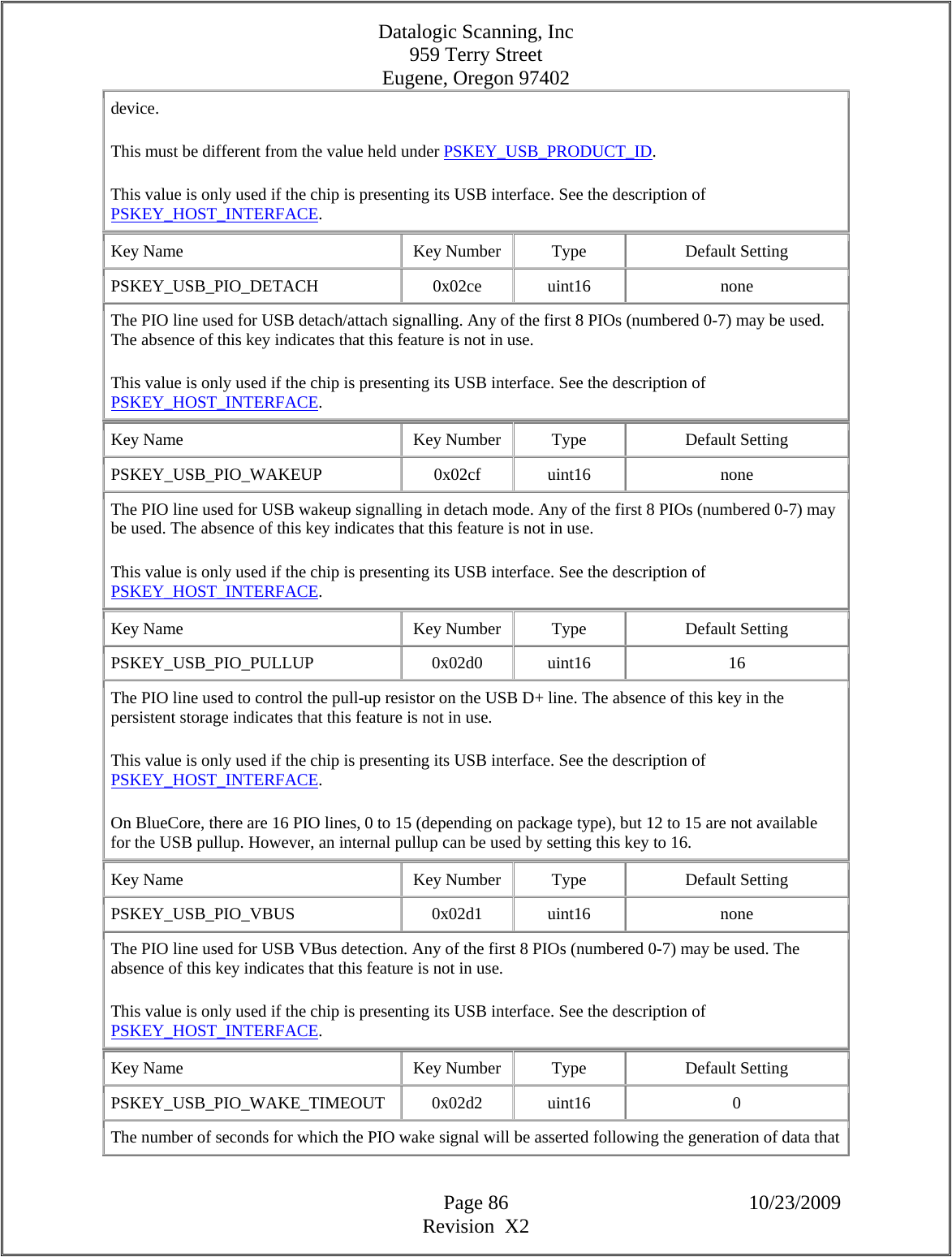
![Datalogic Scanning, Inc 959 Terry Street Eugene, Oregon 97402 Page 87 10/23/2009 Revision X2 is to be transmitted to the host. The timeout is reset each time new data is generated. If this value is 0, the signal is asserted indefinitely (or until the host de-asserts detach). This key is useful for hosts that are sometimes unable to respond to the wake signal (e.g. laptops when their lids are closed). If wake is asserted when the host cannot process wake and kept asserted until it is able to process the signal, then the host could be woken up to receive an event which is out of date. The host will, of course, have to process any old events when it does reconnect to a device following a wake timeout. This value is only used if the chip is presenting its USB interface. See the description of PSKEY_HOST_INTERFACE. Key Name Key Number Type Default Setting PSKEY_USB_PIO_RESUME 0x02d3 uint16 none The PIO line used to signal that the USB host wakeup from suspend. Any of the first 8 PIOs (numbered 0-7) may be used. The absence of this key indicates that this feature is not in use. PIO resume is used in place of the bus resume signal for hosts that are unable to respond to the bus signal during suspend e.g. PDAs that power-down the root hub in suspend. The PIO line is high to indicate that the host should resume, low otherwise. It remains asserted until activity is restored on the USB. Setting this PS key is sufficient to enable this feature; no notice is taken of the remote wakeup setting of PSKEY_USB_ATTRIBUTES nor of whether the host has enabled remote wakeup. PSKEY_USB_PIO_RESUME is mutually exclusive with PSKEY_USB_PIO_WAKEUP - both can be enabled simultaneously and assigned to the same PIO pin. This value is only used if the chip is presenting its USB interface. See the description of PSKEY_HOST_INTERFACE. Key Name Key Number Type Default Setting PSKEY_USB_BT_SCO_IF_CLASS_CODES 0x02d4 usbclass 0xe0, 0x01, 0x01 Three bytes giving the class information for the USB "Interface Descriptor" (as defined in Table 9.9 of version 1.1 of the USB specification) which contains the SCO endpoints. This PS key enables different class codes to be used for the BT SCO interface from the main BT interface (which contains the control, event and acl endpoints and whose class codes are given by PSKEY_USB_BT_IF_CLASS_CODES). The advantage of this is that the host OS can load different drivers to communicate with each of the interfaces. This is expected to be of use for Microsoft's XP OS in which the in-built BT USB driver will not give access to the SCO endpoints. Type usbclass is held as a uint16[3]. The three values are held in the lower byte of each of the array in the order: { class, subclass, protocol }.](https://usermanual.wiki/Datalogic-ADC/DLBTMCX.User-manual-RF-module/User-Guide-1192966-Page-87.png)
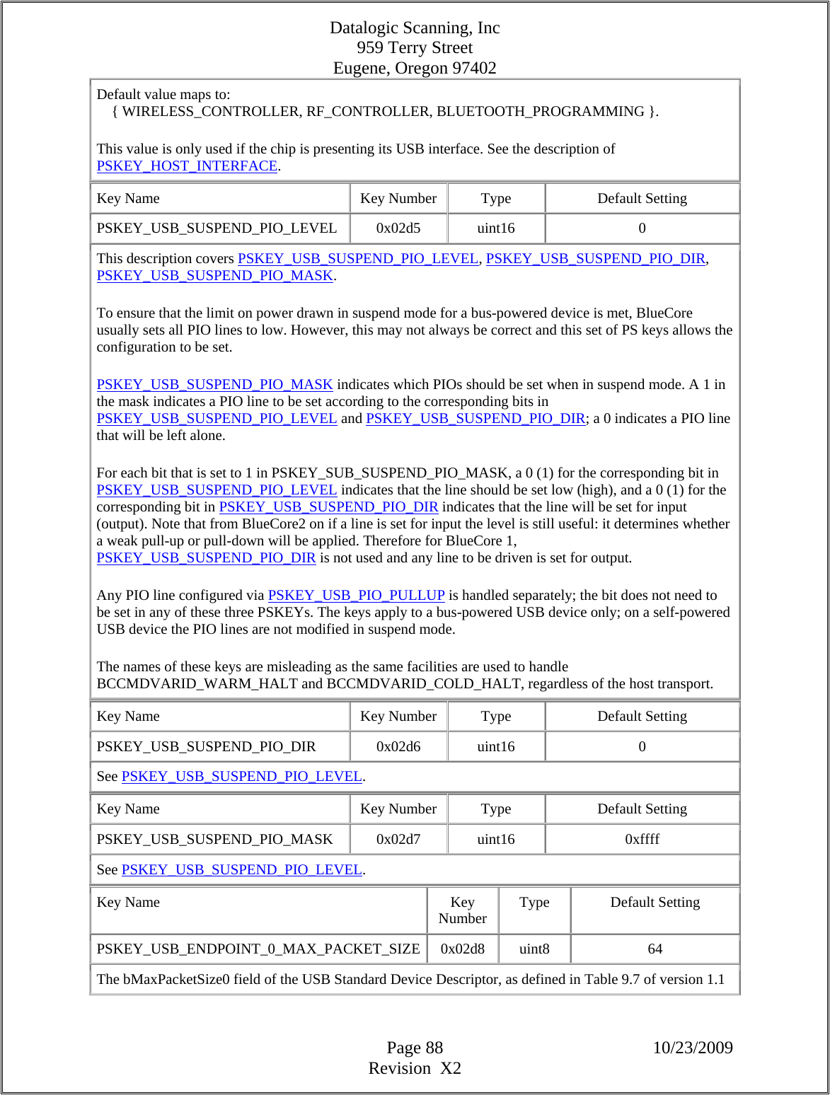
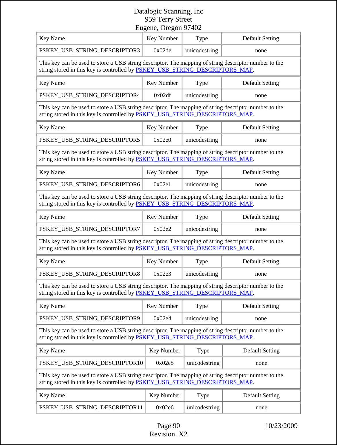
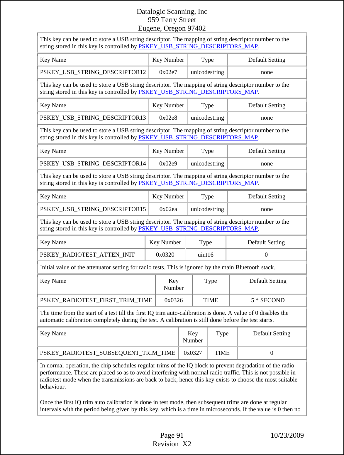
![Datalogic Scanning, Inc 959 Terry Street Eugene, Oregon 97402 Page 89 10/23/2009 Revision X2 of the USB specification. Only values 8, 16, 32 and 64 are valid for this field. This value is only used if the chip is presenting its USB interface. See the description of PSKEY_HOST_INTERFACE. Key Name Key Number Type Default Setting PSKEY_USB_CONFIG 0x02d9 uint16 0x30 This key modifies the behaviour of the USB interface code. It should only be configured on advice from CSR. Key Name Key Number Type Default Setting PSKEY_USB_STRING_DESCRIPTORS_MAP 0x02da uint16[] none This key maps USB string descriptor indexes to the PSKEY numbers containing the string descriptors for those indexes. Each uint16 pair maps a string index to a PSKEY number. The format of this key is therefore: {string_index, pskey_number}, {string_index, pskey_number}, ... If string descriptor index 8 is to be mapped to the string contained in PSKEY 15 and string descriptor index 6 is to be mapped to the string contained in PSKEY 3 then PSKEY_USB_STRING_DESCRIPTORS_MAP would be set as follows: {8, 15} , {6, 3} The PSKEY_USB_STRING_DESCRIPTORn keys were created to provide a convenient set of keys in which to store USB string descriptor strings. Key Name Key Number Type Default Setting PSKEY_USB_STRING_DESCRIPTOR0 0x02db unicodestring none This key can be used to store a USB string descriptor. The mapping of string descriptor number to the string stored in this key is controlled by PSKEY_USB_STRING_DESCRIPTORS_MAP. Key Name Key Number Type Default Setting PSKEY_USB_STRING_DESCRIPTOR1 0x02dc unicodestring none This key can be used to store a USB string descriptor. The mapping of string descriptor number to the string stored in this key is controlled by PSKEY_USB_STRING_DESCRIPTORS_MAP. Key Name Key Number Type Default Setting PSKEY_USB_STRING_DESCRIPTOR2 0x02dd unicodestring none This key can be used to store a USB string descriptor. The mapping of string descriptor number to the string stored in this key is controlled by PSKEY_USB_STRING_DESCRIPTORS_MAP.](https://usermanual.wiki/Datalogic-ADC/DLBTMCX.User-manual-RF-module/User-Guide-1192966-Page-89.png)
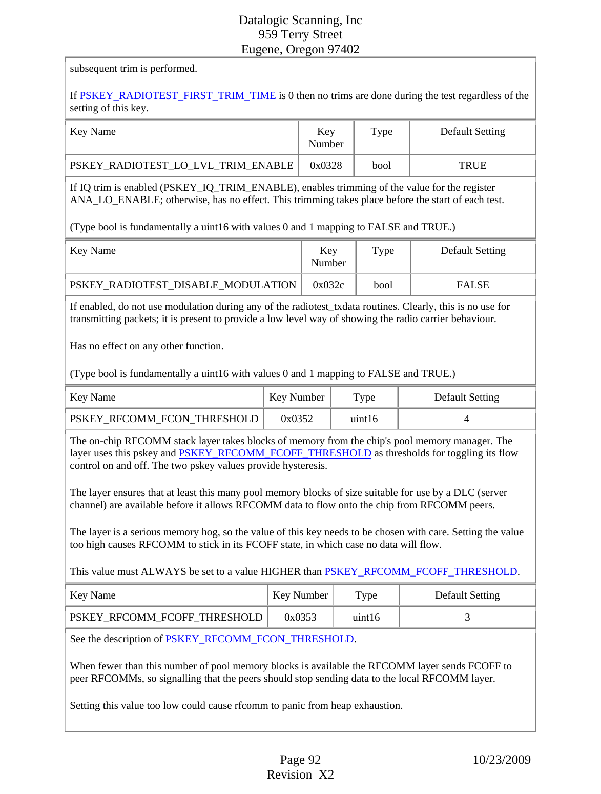
![Datalogic Scanning, Inc 959 Terry Street Eugene, Oregon 97402 Page 93 10/23/2009 Revision X2 This must be lower than PSKEY_RFCOMM_FCON_THRESHOLD. Key Name Key Number Type Default Setting PSKEY_IPV6_STATIC_ADDR 0x0354 uint16[] none The static IPv6 address assigned to the local device. The address is stored as eight 16-bit words corresponding directly to the conventional uncompressed text representation of IPv6 addresses. For example, the IPv6 address 1234:0:0:0:0:0:0:5678 is stored as { 0x1234, 0, 0, 0, 0, 0, 0, 0x5678 }. If this key is not defined then the local device's IPv6 addresses will only include the link-local address derived from the Bluetooth address and any autoconfigured address. Key Name Key Number Type Default Setting PSKEY_IPV4_STATIC_ADDR 0x0355 uint32 none The static IPv4 address assigned to the local device. The address is stored as a 32-bit value in standard network form. For example, the IPv4 address 192.168.1.2 is stored as 0xc0a80102. If this key is not defined then the local device's IPv4 addresses will only include a randomly-derived link-local address and any autoconfigured address. If this key is defined, PSKEY_IPV4_STATIC_SUBNET_MASK should also be defined. Key Name Key Number Type Default Setting PSKEY_IPV6_STATIC_PREFIX_LEN 0x0356 uint8 none The static IPv6 prefix length (applied w.r.t. PSKEY_IPV6_STATIC_ADDR) assigned to the local device. The prefix length is measured in bits. This key should be defined if PSKEY_IPV6_STATIC_ADDR is. If this key is defined, PSKEY_IPV6_STATIC_ROUTER_ADDR should also be defined. Key Name Key Number Type Default Setting PSKEY_IPV6_STATIC_ROUTER_ADDR 0x0357 uint16[] none The static IPv6 address assigned to the subnet router (gateway). The address is stored as eight 16-bit words corresponding directly to the conventional uncompressed text representation of IPv6 addresses. For example, the IPv6 address 1234:0:0:0:0:0:0:cafe is stored as { 0x1234, 0, 0, 0, 0, 0, 0, 0xcafe }. This key should be defined if PSKEY_IPV6_STATIC_PREFIX_LEN is. The subnet router and the local device should share the same prefix.](https://usermanual.wiki/Datalogic-ADC/DLBTMCX.User-manual-RF-module/User-Guide-1192966-Page-93.png)
![Datalogic Scanning, Inc 959 Terry Street Eugene, Oregon 97402 Page 94 10/23/2009 Revision X2 Key Name Key Number Type Default Setting PSKEY_IPV4_STATIC_SUBNET_MASK 0x0358 uint32 none The static IPv4 subnet mask (applied w.r.t. PSKEY_IPV4_STATIC_ADDR) assigned to the local device. The mask is stored as a 32-bit value in standard network form. For example, the subnet mask 255.255.248.0 is stored as 0xfffff800. This key should be defined if PSKEY_IPV4_STATIC_ADDR is. If this key is defined, PSKEY_IPV4_STATIC_ROUTER_ADDR should also be defined. Key Name Key Number Type Default Setting PSKEY_IPV4_STATIC_ROUTER_ADDR 0x0359 uint32 none The static IPv4 address assigned to the subnet router (gateway). The address is stored as a 32-bit value in standard network form. For example, the IPv4 address 192.168.1.254 is stored as 0xc0a801fe. This key should be defined if PSKEY_IPV4_STATIC_SUBNET_MASK is. The subnet router and the local device should be on the same subnet. Key Name Key Number Type Default Setting PSKEY_MDNS_NAME 0x035a char[] none The name assigned to the local device for the purposes of multicast DNS. The name must not include a trailing NUL, and must not be more than 16 characters long. It must be a label, not be a FQDN (i.e. must not contain dots). All letters must be in lowercase. Key Name Key Number Type Default Setting PSKEY_FIXED_PIN 0x035b uint8[] none The fixed PIN assigned to the local device. This must have a length greater than zero (and less than 17). Key Name Key Number Type Default Setting PSKEY_MDNS_PORT 0x035c uint16 5353 The port number to be used by the local device for multicast DNS. Key Name Key Number Type Default Setting PSKEY_MDNS_TTL 0x035d uint8 1 The TTL (Hop Limit for IPv6) to be used by the local device for multicast DNS. Key Name Key Number Type Default Setting PSKEY_MDNS_IPV4_ADDR 0x035e uint32 0xe00000fb](https://usermanual.wiki/Datalogic-ADC/DLBTMCX.User-manual-RF-module/User-Guide-1192966-Page-94.png)
![Datalogic Scanning, Inc 959 Terry Street Eugene, Oregon 97402 Page 95 10/23/2009 Revision X2 The IPv4 address to be used by the local device for multicast DNS. The address is stored as a 32-bit value in standard network form. For example, the IPv4 address 224.0.0.251 is stored as 0xe00000fb. Key Name Key Number Type Default Setting PSKEY_ARP_CACHE_TIMEOUT 0x035f uint16 120 The time in seconds before an ARP cache entry is considered stale and hence is rechecked (via an ARP request) when it is next used. Key Name Key Number Type Default Setting PSKEY_HFP_POWER_TABLE 0x0360 uint16[] none This PS key configures the HFP library power table. Key Name Key Number Type Default Setting PSKEY_RX_ATTEN_CONFIG 0x038b uint16[] 0, 0x01, 0x02, 0x03, 0x04, 0x05, 0x06, 0x07, 0x47, 0x57, 0x67, 0x77, 0xB7, 0xF7, 0xF7, 0xF7 A table of various attenuation values used by the automatic gain control hardware in BC5 and later chips. Each 8 bit value in the table defines the various attenuator values as follows: Bits [2:0] ANA_RX_ATTEN Bits [5:4] ANA_RX_MIX_ATTEN Bits [7:6] ANA_RX_I2I_ATTEN The supplied values of ANA_RX_I2I_ATTEN must increase monotonically. See also PSKEY_I2I_WB_LO_THRESHOLD and PSKEY_I2I_WB_HI_THRESHOLD. Key Name Key Number Type Default Setting PSKEY_GBL_CLK_RATE2 0x038c uint16 0 Controls high-speed operating modes of the chip. This PSKEY should only be changed on advice from CSR. Key Name Key Number Type Default Setting PSKEY_SLOW_CLOCK_FILTER_DIVIDER 0x0390 uint16 3333 The reciprocal of the fraction of the currently calibrated slow clock period by which the filtered value must differ from the calibrated period in order to cause a recalibration. The value default value corresponds to 300 ppm. See also the description of PSKEY_SLOW_CLOCK_FILTER_SHIFT. Key Name Key Number Type Default Setting PSKEY_SLOW_CLOCK_FILTER_SHIFT 0x0391 uint16 5](https://usermanual.wiki/Datalogic-ADC/DLBTMCX.User-manual-RF-module/User-Guide-1192966-Page-95.png)
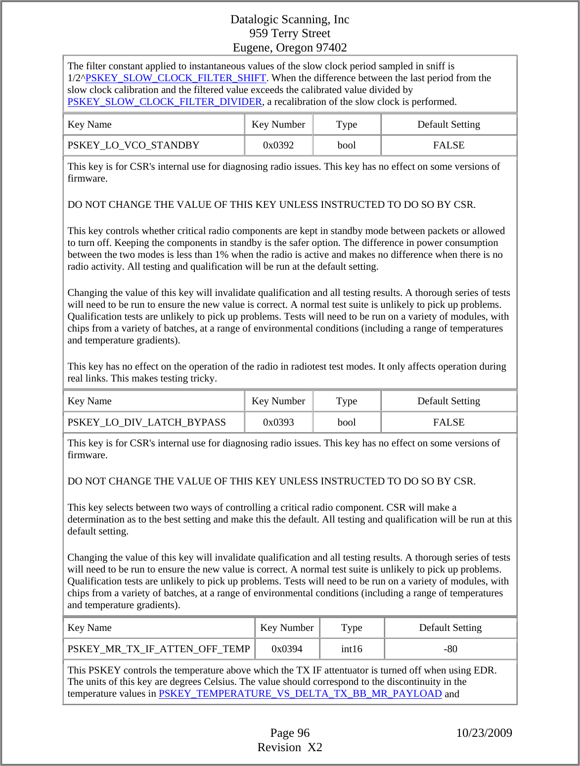
![Datalogic Scanning, Inc 959 Terry Street Eugene, Oregon 97402 Page 97 10/23/2009 Revision X2 PSKEY_TEMPERATURE_VS_DELTA_TX_BB_MR_HEADER. The basic rate setting is controlled by PSKEY_ANALOGUE_ATTENUATOR. (The abbreviation MR for Medium Rate is used consistently in place of EDR for Enhanced Data Rate throughout the PS keys as many were introduced before the abbreviation EDR came into use.) Key Name Key Number Type Default Setting PSKEY_AMUX_CLOCK 0x0398 uint16 AMUX_CLK_OFF This PSKEY controls the frequency of the clock available through the analogue multiplexer. To use this control, the chip must have the AMUX clock deglitcher circuit and PSKEY_AMUX_AIO0 must be set to 'AMUX'. The drop-down box options in this control are only correct for BC4-Headset, BC4_Audio Flash. Other chips may not output the advertised clock or may only output a subset of the clocks. Key Name Key Number Type Default Setting PSKEY_PIO_WAKEUP_STATE 0x039f uint16 0xFFFF Controls the state for each PIO line (0 to 15) that will wake the chip from deep sleep. Each bit corresponds to a PIO line. Setting a bit high will result in the chip waking when that line goes high, setting the bit low will cause the chip to wake when the line goes low. The PIO lines must already have been configured to wake the chip using either PSKEY_DEEP_SLEEP_PIO_WAKE or the VM. Key Name Key Number Type Default Setting PSKEY_PROG_BRANCH_MODE 0x03a1 uint16 3 The branch prediction mode to use for the program memory. This PSKEY should only be changed on advice from CSR. Key Name Key Number Type Default Setting PSKEY_PROG_WAIT_STATES 0x03a2 uint16 1 The number of wait states to use for the program memory. This pskey should only be changed on advice from CSR. Key Name Key Number Type Default Setting PSKEY_TX_PRE_LVL_CLASS1 0x03a8 uint8 8 Sets the level of the transmitter pre-amplifier when used with class 1 operation. Otherwise the same as PSKEY_TX_PRE_LVL. Key Name Key Number Type Default Setting PSKEY_RX_MR_EQ_TAPS 0x03a9 uint16[] 0x1AB2, 0x0F1C, 0x1D11, 0x2BD3 Set the default value for the four RX_MR_EQ_TAPS configuration registers used for Enhanced Data Rate](https://usermanual.wiki/Datalogic-ADC/DLBTMCX.User-manual-RF-module/User-Guide-1192966-Page-97.png)
![Datalogic Scanning, Inc 959 Terry Street Eugene, Oregon 97402 Page 98 10/23/2009 Revision X2 reception. Change only on advice from CSR. (The abbreviation MR for Medium Rate is used consistently in place of EDR for Enhanced Data Rate throughout the PS keys as many were introduced before the abbreviation EDR came into use.) Key Name Key Number Type Default Setting PSKEY_TEMPERATURE_VS_DELTA_TX_BB_MR_PAYLOAD 0x03aa temperature_calibration[] { -10, 5 }, { 20, 0 }, { 40, -2 } The value is a table in the same format as PSKEY_TEMPERATURE_VS_DELTA_INTERNAL_PA. The values of the table (even-numbered 16-bit words) in this case are an adjustment applied separately to both the top nybbles of PSKEY_TX_FILTER_CONFIG when transmitting the payload of a packet at Enhanced Data Rate; hence they must lie in the range -15 to 15. The adjusted nybbles will be limited to the range 0 to 15. Note that, using the default values, there is a discontinuity in the values in this key at 55 deg C, which corresponds to switching off the TX IF attenuator (see PSKEY_MR_TX_IF_ATTEN_OFF_TEMP). Since BlueCore can only measure temperatures at a resolution of 1 deg C, this is represented by two consecutive values at 54 and 55 deg C. (The abbreviation MR for Medium Rate is used consistently in place of EDR for Enhanced Data Rate throughout the PS keys as many were introduced before the abbreviation EDR came into use.) Key Name Key Number Type Default Setting PSKEY_TEMPERATURE_VS_DELTA_TX_BB_MR_HEADER 0x03ab temperature_calibration[] { -10, 5 }, { 20, 0 }, { 40, -2 } The value is a table in the same format as PSKEY_TEMPERATURE_VS_DELTA_INTERNAL_PA. The values of the table (even-numbered 16-bit words) in this case are an adjustment applied separately to both the top nybbles of PSKEY_TX_FILTER_CONFIG when transmitting the header of a packet at Enhanced Data Rate; hence they must lie in the range -15 to 15. The adjusted nybbles will be limited to the range 0 to 15. Note that, using the default values, there is a discontinuity in the values in this key at 55 deg C, which corresponds to switching off the TX IF attenuator (see PSKEY_MR_TX_IF_ATTEN_OFF_TEMP). Since BlueCore can only measure temperatures at a resolution of 1 deg C, this is represented by two consecutive values at 54 and 55 deg C. (The abbreviation MR for Medium Rate is used consistently in place of EDR for Enhanced Data Rate throughout the PS keys as many were introduced before the abbreviation EDR came into use.) Key Name Key Number Type Default Setting PSKEY_TEMPERATURE_VS_DELTA_INTERNAL_PA_CLASS1 0x03ae temperature_calibration[] none Table in the same form as PSKEY_TEMPERATURE_VS_DELTA_INTERNAL_PA used when transmitting at](https://usermanual.wiki/Datalogic-ADC/DLBTMCX.User-manual-RF-module/User-Guide-1192966-Page-98.png)
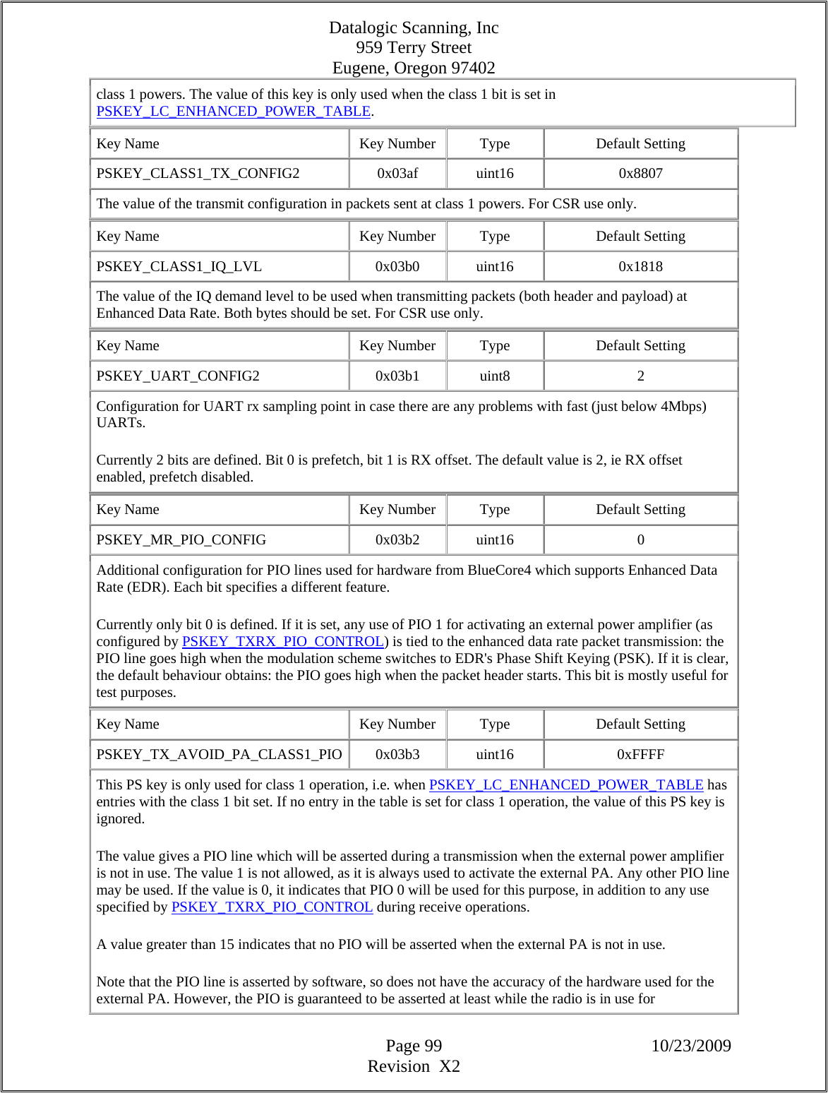
![Datalogic Scanning, Inc 959 Terry Street Eugene, Oregon 97402 Page 100 10/23/2009 Revision X2 transmission. Key Name Key Number Type Default Setting PSKEY_INITIAL_PIO_STATE 0x03b5 uint16[] none This key may be used to set the initial state of the PIO pins prior to the VM application running. The key is an array of uint16s which can be considered to have the following structure:- struct { uint16 mask; uint16 direction; uint16 level; uint16 bias; uint16 buskeep_en; uint16 disable_pull; } Each word within the structure can be considered to be an array of bits corresponding to individual PIO pins. The mask word is used to control which PIO pins are controlled by this key. Note that PIOs which are assigned to firmware functions (including those masked by PSKEY_PIO_PROTECT_MASK) are also masked out. The direction word is used to control pin direction:- 0 = input 1 = output The level word is optional and controls pin output levels:- 0 = low 1 = high From BlueCore2-External on, for pins set as inputs by the direction word, the corresponding bits in this word determine the direction of a weak pull device (0=pull-down, 1=pull-up). If the word is not present, pins will be set to their default power-on levels. The bias word is optional and controls the strength of the bias applied to pins configured as input:- 0 = weak bias 1 = strong bias If the word is not present, pins will be set to their default power-on bias strength. The buskeep_en word is optional and controls whether "bus-keeper" functionality (see PSKEY_BCSP_PULL_CONTROL) is enabled for pins configured as inputs, on chips which support this:- 0 = bus-keeper disabled 1 = bus-keeper enabled If the word is not present, no bus-keepers will be enabled. The disable_pull word is optional and controls whether the internal pull device is disabled (see PSKEY_BCSP_PULL_CONTROL) for pins configured as inputs, on chips which support this. (These bits have no effect on pins configured as outputs.) 0 = pull device enabled 1 = pull device disabled If the word is not present, pull devices will be enabled. NOTE: disabling pull devices when pins are not driven externally can lead to excessive current consumption and potentially damage the chip. Example ------- To set PIO 3 as an output driving a high signal and PIO 5 as an input with strong-bias set the key to (0x0028,0x0008,0x0008,0x0020). mask = 0x0028 # (1<<5 | 1<<3) direction = 0x0008 # (1<<3) level = 0x0008 # (1<<3) bias = 0x0020 # (1<<5) Key Name Key Number Type Default Setting](https://usermanual.wiki/Datalogic-ADC/DLBTMCX.User-manual-RF-module/User-Guide-1192966-Page-100.png)
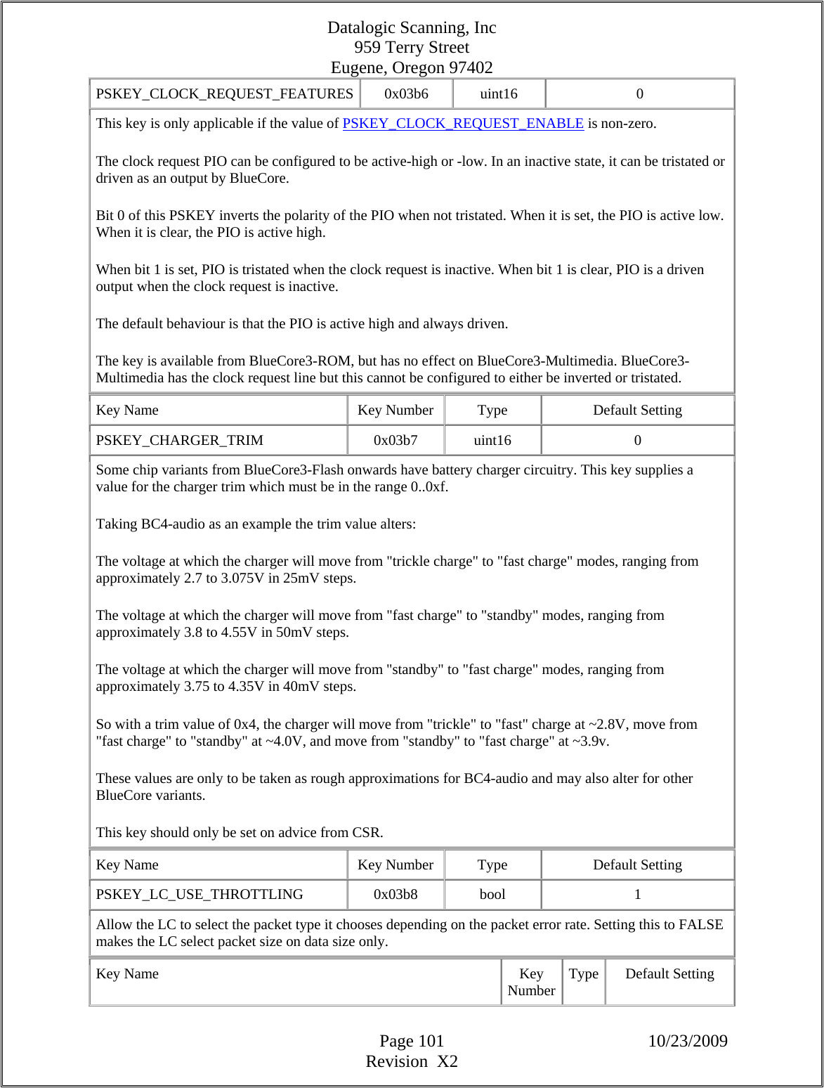
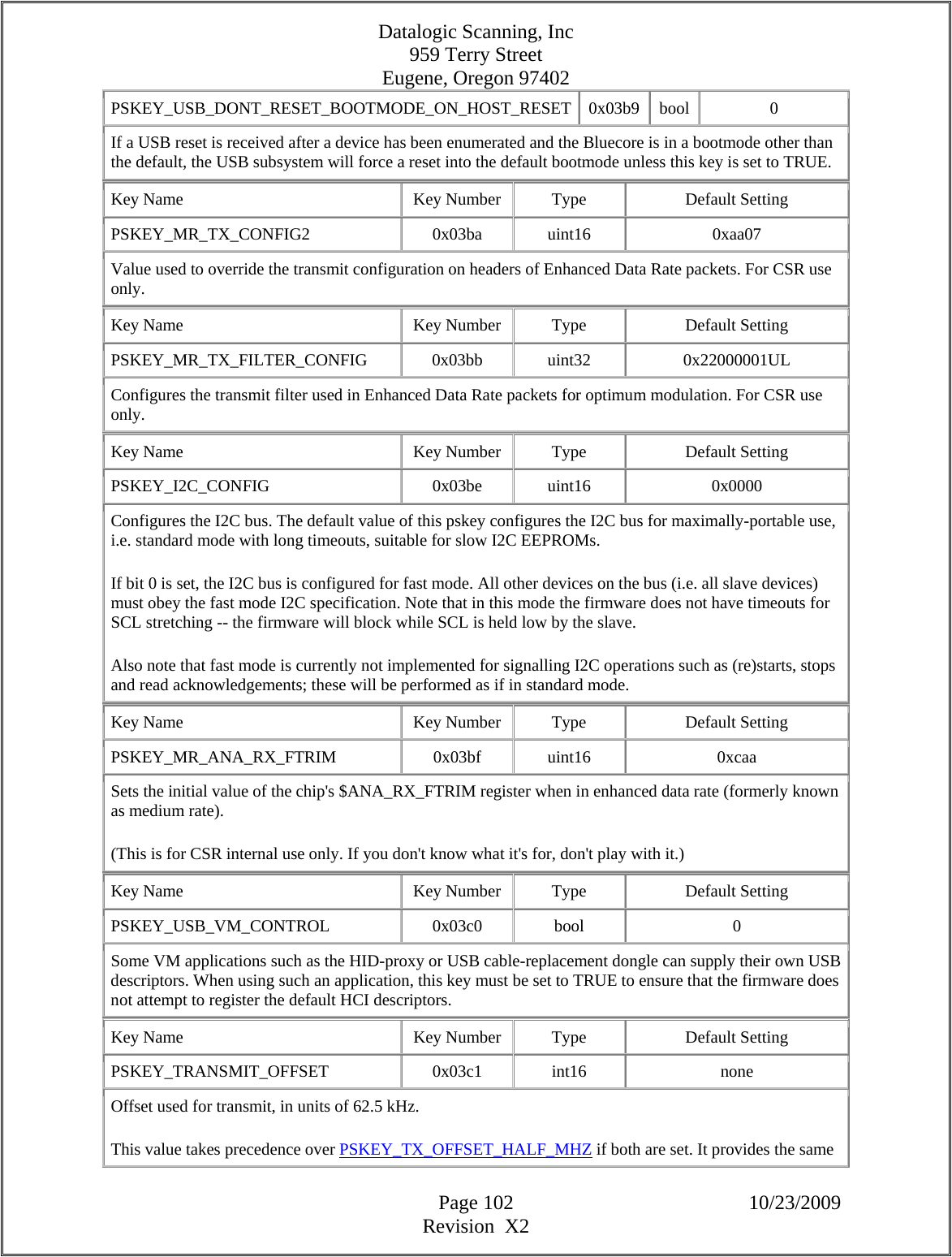
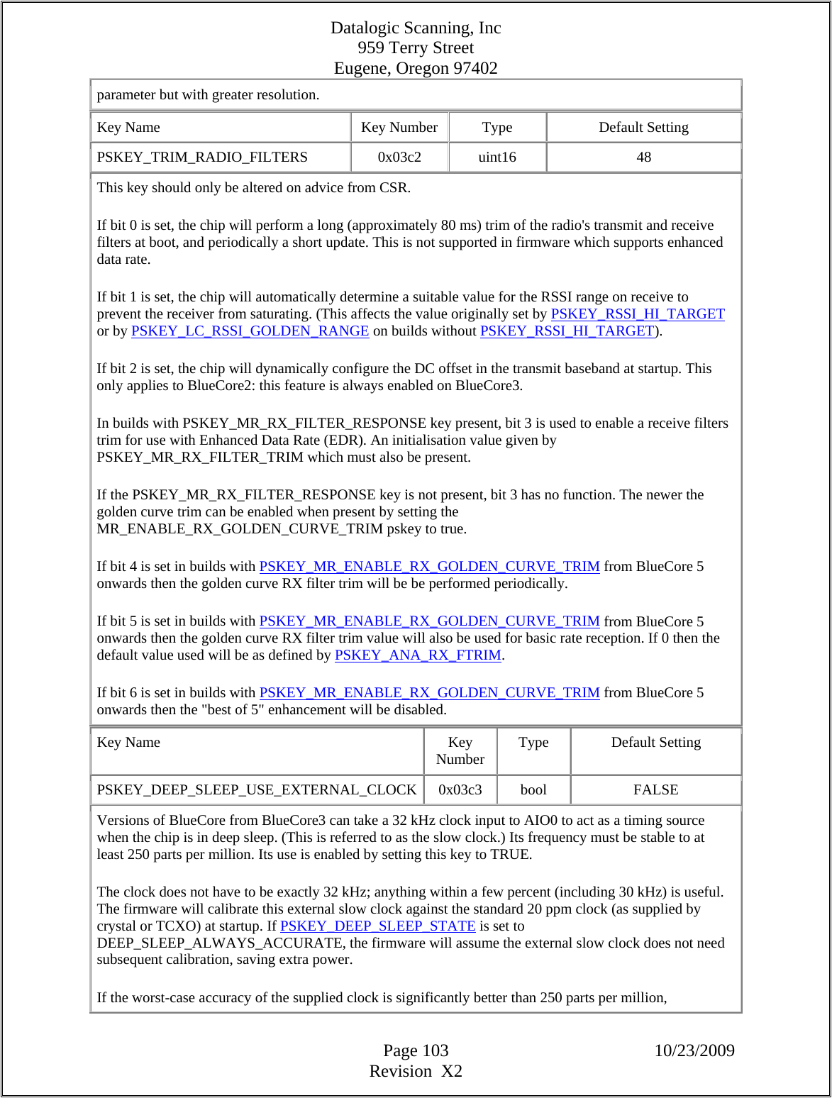
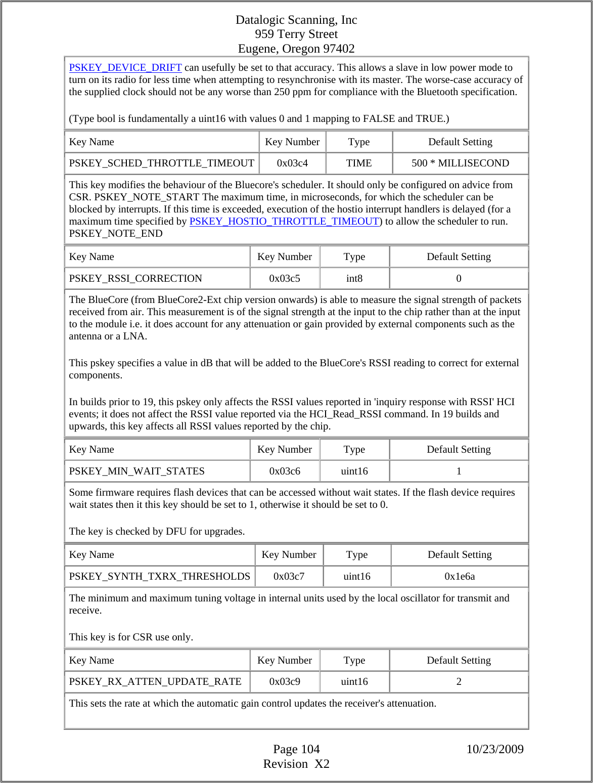
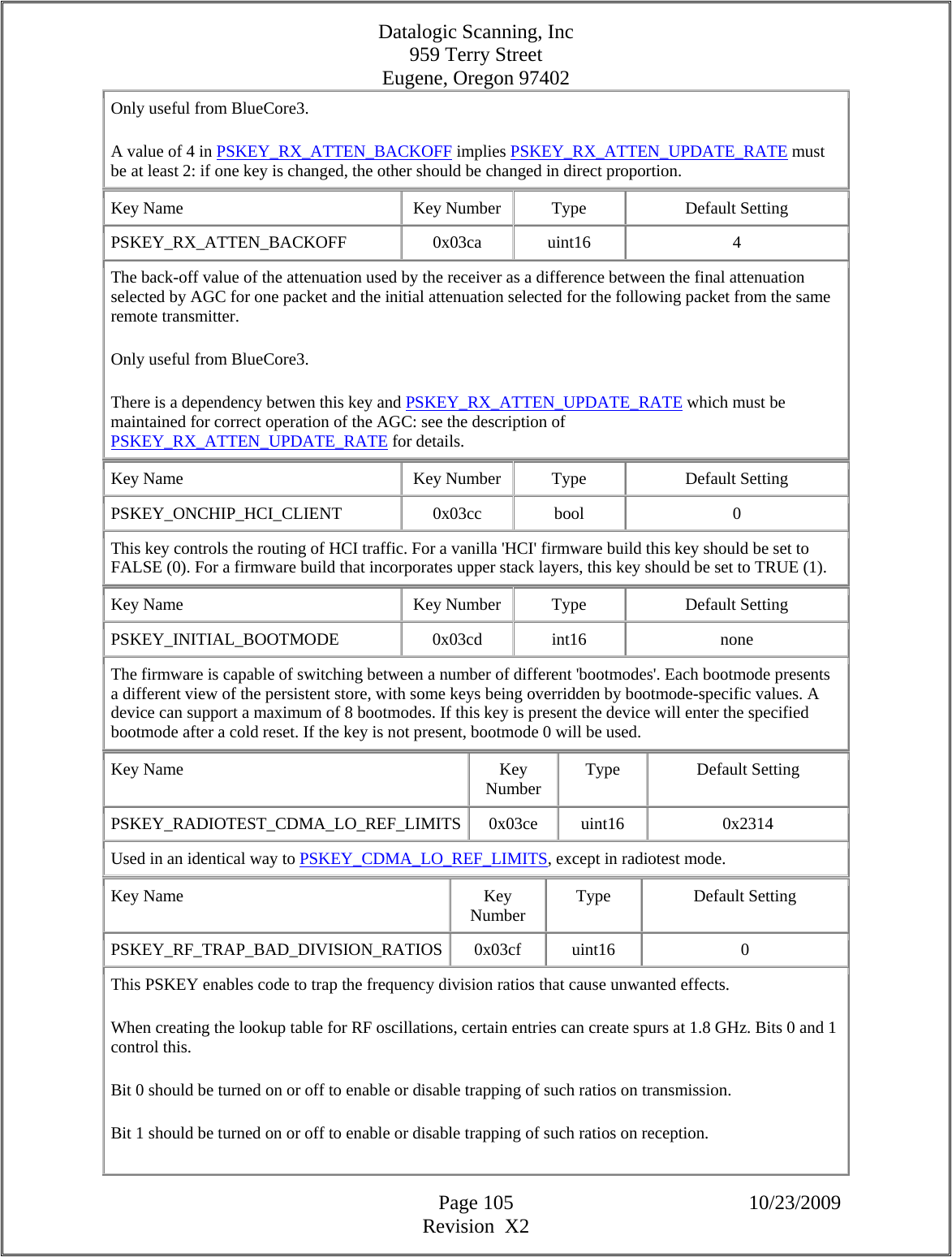
![Datalogic Scanning, Inc 959 Terry Street Eugene, Oregon 97402 Page 106 10/23/2009 Revision X2 Bit 2 should be turned on or off to enable or disable trapping of division ratios that clash with the 48 MHz USB clock. Key Name Key Number Type Default Setting PSKEY_TEST_FORCE_OFFSET 0x03d3 bool FALSE This key modifies the behaviour of PSKEY_TEST_DELTA_OFFSET. It should only be configured on advice from CSR. Key Name Key Number Type Default Setting PSKEY_RX_DYNAMIC_LVL_OFFSET 0x03d4 uint16 0 The value of this key is added to the receiver level to optimise certain channels during reception. It consists of four four-bit fields. Bits 0 to 3 control the behaviour at resonance, bits 4 to 7 one channel away, bits 8 to 11 two channels away, and bits 12 to 15 three channels away. Key Name Key Number Type Default Setting PSKEY_TEST_DELTA_OFFSET 0x03d6 uint16 0 This offset is applied to the frequency trim in certain test modes. The value zero is equivalent to normal operation. It should only be configured on advice from CSR. Key Name Key Number Type Default Setting PSKEY_TEMPERATURE_VS_DELTA_ANA_FTRIM 0x03d7 temperature_calibration[] none The value is a table in the same format as PSKEY_TEMPERATURE_VS_DELTA_INTERNAL_PA. The values of the table (even-numbered 16-bit words) in this case are an adjustment applied separately to PSKEY_ANA_FTRIM. Key Name Key Number Type Default Setting PSKEY_TEMPERATURE_VS_DELTA_TX_BB 0x03d8 temperature_calibration[] { -40, 8 }, { -30, 8 }, { 20, 0 }, { 50, -3 }, { 60, -2 }, { 80, -5 }, { 100, -7 } The value is a table in the same format as PSKEY_TEMPERATURE_VS_DELTA_INTERNAL_PA. The values of the table (even-numbered 16-bit words) in this case are an adjustment applied separately to both the top nybbles of PSKEY_TX_FILTER_CONFIG; hence they must lie in the range -15 to 15. The adjusted nybbles will be limited to the range 0 to 15. Key Name Key Number Type Default Setting PSKEY_TEMPERATURE_VS_DELTA_TX_PRE_LVL 0x03d9 temperature_calibration[] none The value is a table in the same format as PSKEY_TEMPERATURE_VS_DELTA_INTERNAL_PA. The values of the table (even-numbered 16-bit words) in this case are an adjustment applied to PSKEY_TX_PRE_LVL which should be in the range -15 to 15. The adjusted value will be limited to the](https://usermanual.wiki/Datalogic-ADC/DLBTMCX.User-manual-RF-module/User-Guide-1192966-Page-106.png)
![Datalogic Scanning, Inc 959 Terry Street Eugene, Oregon 97402 Page 107 10/23/2009 Revision X2 range 0 to 15. Key Name Key Number Type Default Setting PSKEY_TEMPERATURE_VS_DELTA_INTERNAL_PA 0x03da temperature_calibration[] { -40, -1 }, { -30, 0 }, { 50, 0 }, { 60, 1 }, { 100, 2 } The value consists of a table of pairs of 16-bit signed values, as many pairs as necessary. Each pair is in a similar format to PSKEY_TEMPERATURE_CALIBRATION: the first value is a temperature in degrees Celsius, while in this case the second is a signed correction to be made to the internal PA setting at that temperature. The value will be interpolated linearly between those settings, but will not be extrapolated beyond the end of the temperature range. The temperatures should increase monotonically, but the corrections at each temperature need not. Key Name Key Number Type Default Setting PSKEY_TEMPERATURE_CALIBRATION 0x03db temperature_calibration 0x0017, 0x6980 This value must be set to enable temperature compensation which is available from some BC2-ROM versions and all later parts. It is used to calibrate the internal thermometer and can be set separately for each individual chip. It consists of two words. The first word is the calibration temperature in degrees Celsius stored as an int16. The second word is a uint16 comprising of two 8 bit fields. Pre BC5 they are coded as: - Lower 8 bits: the value read from ADC channel 1 (at cal temp) - Upper 8 bits: the value read from ADC channel 36 (at cal temp) Post BC5 they are coded as: - Lower 8 bits: ADC channel 1 coded as 10 bits - 700 (at cal temp) - Upper 8 bits: ADC channel 36 coded as 10 bits - 300 (at cal temp) All three readings must be made together. Pre BC5 ADC values are simply the values returned from the standard BCCMD ADC interface. Post BC5 the (8 bit) BCCMD ADC readings need to be multiplied by 4 and then 700 or 300 subtracted from the result to obtain the 8 bit values for the pskeys (as shown above). To turn temperature compensation off, both words should be set to zero. (Note that this must be *two* zero 16-bit words, as zero is an acceptable value for the temperature in degrees Celsius.) Note that in version 17 of the firmware and before the second reading was made from channel 10. This will not work for chips starting with BlueCore3. However, from version 18 onwards channel 36 maps to the correct channel for the temperature reading regardless of the underlying hardware.](https://usermanual.wiki/Datalogic-ADC/DLBTMCX.User-manual-RF-module/User-Guide-1192966-Page-107.png)
![Datalogic Scanning, Inc 959 Terry Street Eugene, Oregon 97402 Page 108 10/23/2009 Revision X2 Key Name Key Number Type Default Setting PSKEY_DEEP_SLEEP_CORRECTION_FACTOR 0x03dc int16 3 In deep sleep, BlueCore has a low power oscillator circuit which is used to keep time. Different variants of the chip have slightly different behaviour. This key allows the correction for the chip to be tweaked: lower (signed) values make the clock run slower, and higher values make it run faster. This should only need to be changed for different hardware; therefore, the value should only be altered on advice from CSR. The value is not applied if PSKEY_DEEP_SLEEP_USE_EXTERNAL_CLOCK is TRUE as the external clock will not have the same systematic behaviour. Key Name Key Number Type Default Setting PSKEY_CLOCK_STARTUP_DELAY 0x03dd uint16 0 On waking from deep sleep, BlueCore usually expects an external clock supplied to the chip to be stable within 5 milliseconds of the clock request line being asserted. If this is not the case, special action must be taken to avoid loss of clock accuracy. In particular, the clock accuracy must not fall below 250 parts per million while there are Bluetooth connections to the device. On BlueCore2-ROM, this key should be set to the maximum time in milliseconds which it will take an external clock to stabilise. This results in slightly less efficient power consumption on entry to and exit from deep sleep. It has no effect if the value is less than 6 milliseconds, or if no clock request line is in use. On BlueCore3 and later, a value from 1 to 31 inclusive is used directly as count of cycles of the low power oscillator (LPO). Setting a value of zero (the default) causes a delay of 5 cycles to be used. The frequency of the internal LPO is nominally 1 kHz but varies somewhat between individual chips, so care should be taken when picking a suitable value. When supplying an external slow clock (see PSKEY_DEEP_SLEEP_USE_EXTERNAL_CLOCK), the nominal 32 kHz clock is divided by 32 before use. Key Name Key Number Type Default Setting PSKEY_CDMA_LO_ERROR_LIMITS 0x03de uint16 0x140F This value is used in the run-time generation of the local oscillator configuration table when using a CDMA (non n*250 kHz) reference clock. Bits [7:0] define the maximum acceptable local oscillator frequency error on transmit in uints of 1 kHz when using the preferred frequency offset. Bits [15:8] define the maximum allowed local oscillator frequency error in units of 1 kHz to terminate the search. Available from BlueCore2-ROM only. Key Name Key Number Type Default Setting PSKEY_CDMA_LO_REF_LIMITS 0x03df uint16 0x2314 This value is used in the run-time generation of the local oscillator configuration table when using a CDMA (non n*250 kHz) reference clock.](https://usermanual.wiki/Datalogic-ADC/DLBTMCX.User-manual-RF-module/User-Guide-1192966-Page-108.png)
![Datalogic Scanning, Inc 959 Terry Street Eugene, Oregon 97402 Page 109 10/23/2009 Revision X2 Bits [7:0] define the minimum allowed local oscillator frequency reference in units of 10 kHz. Bits [15:8] define the maximum allowed local oscillator frequency reference in units of 10 kHz. Available from BlueCore2-ROM only. Key Name Key Number Type Default Setting PSKEY_LOOP_FILTER_TRIM 0x03e4 uint16 0x1c85 Sets a trim for optimising the loop filter to give the best trade-off between phase noise and the time taken for the the synthesiser to settle at the start of each radio packet. Bits [3:0] define the resistor trim for the internal loop filter Bits [7:4] define the capacitor trim for the internal loop filter Bits [11:8] define the phase comparator level; this can be used to optimise both the internal and external loop filters Bit [12] define if we run in single or dual charge pump mode (bc5+ only) 1=use single charge pump mode 0=dual charge pump mode Versions of BlueCore from BlueCore2-ROM only. Key Name Key Number Type Default Setting PSKEY_USB_ATTRIBUTES_POWER 0x03f2 bool none This bit is set if the device is self-powered. This bit is described in table 9-8 in USB spec v1.1 - it corresponds to D6 in Offset 7. Key Name Key Number Type Default Setting PSKEY_USB_ATTRIBUTES_WAKEUP 0x03f3 bool none This bit is set if the device can respond to a remote wake-up command. This bit is described in table 9-8 in USB spec v1.1 - it corresponds to D5 in Offset 7. Key Name Key Number Type Default Setting PSKEY_DFU_ATTRIBUTES_MANIFESTATION_TOLERANT 0x03f4 bool none If this bit is set the device can talk via USB after a firmware upgrade, or it can deal with a second firmware download. If this bit is clear the device can only be reset after a firmware upgrade. Key Name Key Number Type Default Setting PSKEY_DFU_ATTRIBUTES_CAN_UPLOAD 0x03f5 bool none If this bit is set, then the device supports firmware upload to host. Key Name Key Number Type Default Setting PSKEY_DFU_ATTRIBUTES_CAN_DOWNLOAD 0x03f6 bool none If this bit is set, then the device supports firmware download from host.](https://usermanual.wiki/Datalogic-ADC/DLBTMCX.User-manual-RF-module/User-Guide-1192966-Page-109.png)
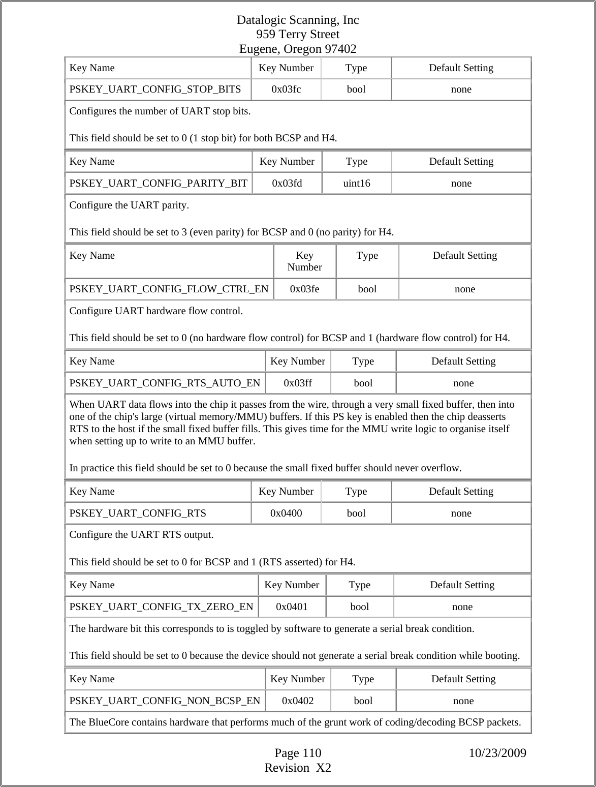
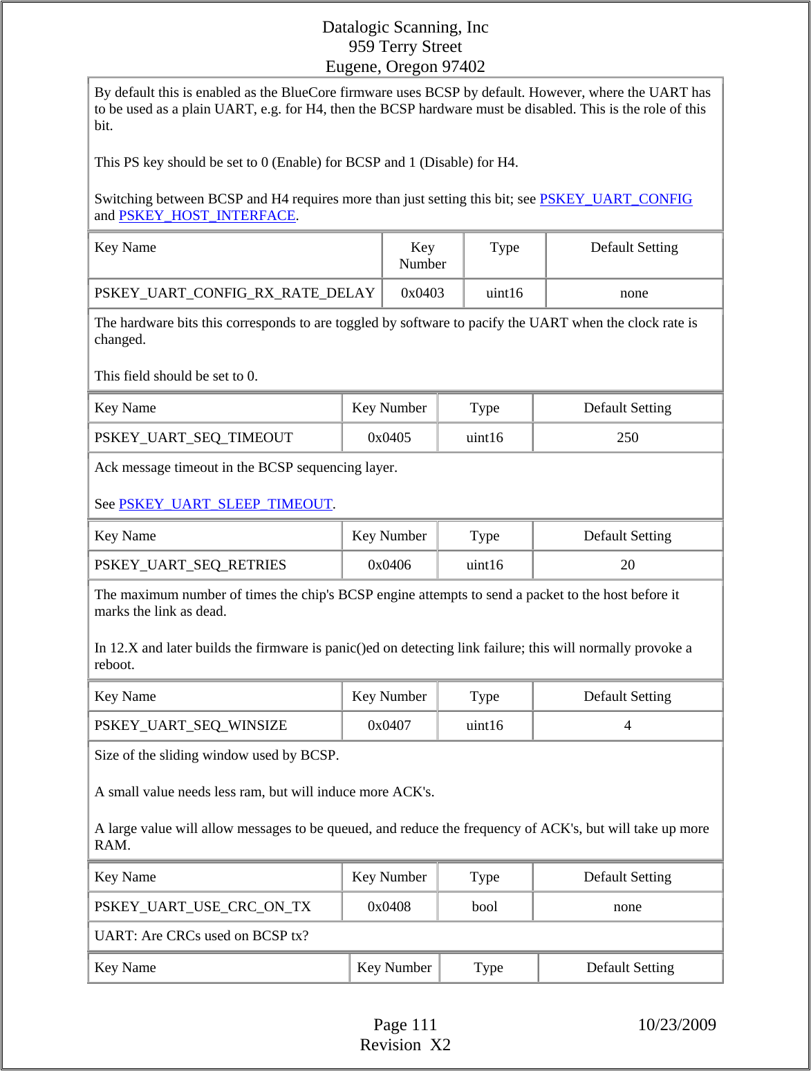
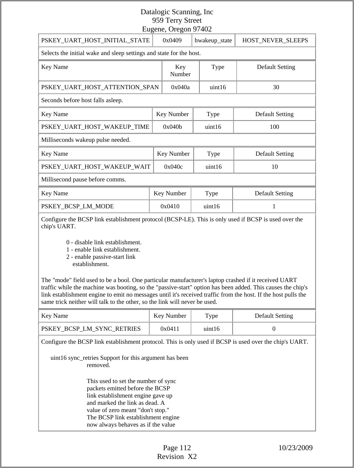
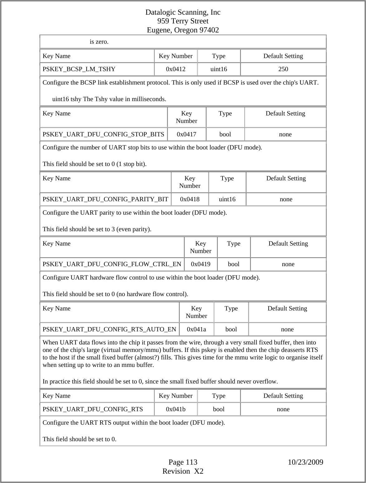
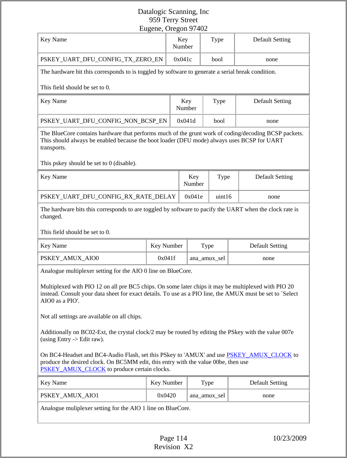
![Datalogic Scanning, Inc 959 Terry Street Eugene, Oregon 97402 Page 115 10/23/2009 Revision X2 Multiplexed with PIO 13 on all pre BC5 chips. On some later chips it may be multiplexed with PIO 21 instead. Consult your data sheet for exact details. To use as a PIO line, the AMUX must be set to `Select AIO1 as a PIO'. The clock routing options are not available on BC3-MM. On BC5 chips write the values 0xbe or 0xfe (using Entry -> Edit Raw) to route the crystal or crystal/2 clock on AIO1 respectively. Key Name Key Number Type Default Setting PSKEY_AMUX_AIO2 0x0421 ana_amux_sel none Analogue muliplexer setting for the AIO 2 line on BlueCore. Multiplexed with PIO 14 where present. To use as a PIO line, the AMUX must be set to `Select AIO2 as a PIO'. Key Name Key Number Type Default Setting PSKEY_AMUX_AIO3 0x0422 ana_amux_sel none Analogue muliplexer setting for the AIO 3 line on BlueCore. Multiplexed with PIO 15 where present. To use as a PIO line, the AMUX must be set to `Select AIO3 as a PIO'. Key Name Key Number Type Default Setting PSKEY_LOCAL_NAME_SIMPLIFIED 0x0423 local_name_complete none On firmware builds prior to 18, the local name is represented in the Persistent Store by a collection of keys. This key provides an easy way to manipulate those keys. See the description at key PSKEY_LOCAL_NAME0 for more information. Key Name Key Number Type Default Setting PSKEY_EXTENDED_STUB 0x2001 uint16 0 A key that can be harmlessly read or written. Key Name Key Number Type Default Setting PSKEY_TEMPERATURE_VS_DELTA_EXTERNAL_PA 0x21b6 temperature_calibration[] { 0, 0 } Table in the same form as PSKEY_TEMPERATURE_VS_DELTA_INTERNAL_PA used for the EXTERNAL power amplifier. This replaces PSKEY_TEMPERATURE_VS_DELTA_EXTERNAL_PA_CLASS1, as the temperature compensation of the external PA is now independent of the external PA switching. Key Name Key Number Type Default Setting PSKEY_SLOW_CLOCK_TEMP_HYSTERESIS_MIN 0x21b8 uint16 1](https://usermanual.wiki/Datalogic-ADC/DLBTMCX.User-manual-RF-module/User-Guide-1192966-Page-115.png)
![Datalogic Scanning, Inc 959 Terry Street Eugene, Oregon 97402 Page 116 10/23/2009 Revision X2 This key works in consort with PSKEY_SLOW_CLOCK_TEMP_HYSTERESIS. See the description of that key for the full description. The units of this key are degrees Celsius. Key Name Key Number Type Default Setting PSKEY_RX_MR_CONFIGS 0x21b9 uint16[] 0x1A17, 0x0001 A set of values used for configuring certain registers for optimum EDR operation. Only to be set on advice from CSR. (The abbreviation MR for Medium Rate is used consistently in place of EDR for Enhanced Data Rate throughout the PS keys as many were introduced before the abbreviation EDR came into use.) Key Name Key Number Type Default Setting PSKEY_PIO_DEEP_SLEEP_EITHER_LEVEL 0x21bd uint32 0 Allows the chip to deep sleep irrespective of the level of the PIO lines. Traditionally BlueCore chips will stay out of deep sleep when any PIO line configured as an input is high. This behaviour can be modified by setting PSKEY_PIO_WAKEUP_STATE so that the chip will stay out of deep sleep when lines are low, but enter deep sleep when the lines are high. Each bit in this PSKEY corresponds to a PIO line from 0 to 31. Note that 31 PIOs may not be present on all BlueCores. Setting a bit will result that PIO's level having no effect on the chip's deep sleep behaviour; the chip will go into deep sleep if the PIO is high or low. The BlueCore will still wakeup to process changes in PIO levels. The PIO lines must already have been configured to wake the chip using either PSKEY_DEEP_SLEEP_PIO_WAKE or the VM. Key Name Key Number Type Default Setting PSKEY_MR_RX_FILTER_TRIM_TEMP_COMP 0x21be temperature_calibration[] {-40, 0 }, {-20, 0 }, { 0, 0 }, { 20, 0 }, { 40, 0 }, { 60, 0 }, { 80, 0 } An array of values used for controlling temperature compensation on some variants of the golden curve EDR filter trim algorithm. Only to be set on advice from CSR. (The abbreviation MR for Medium Rate is used consistently in place of EDR for Enhanced Data Rate throughout the PS keys as many were introduced before the abbreviation EDR came into use.) Key Name Key Number Type Default Setting PSKEY_MR_RX_FILTER_TRIM_BIAS_CONTROL 0x21bf bc5_gc_trim_bias_control 0x0000,](https://usermanual.wiki/Datalogic-ADC/DLBTMCX.User-manual-RF-module/User-Guide-1192966-Page-116.png)
![Datalogic Scanning, Inc 959 Terry Street Eugene, Oregon 97402 Page 117 10/23/2009 Revision X2 0x000e, 0x0018, 0x0010, 0x0008 An opaque value used for configuring some variants of the golden curve EDR filter trim algorithm. Only to be set on advice from CSR. (The abbreviation MR for Medium Rate is used consistently in place of EDR for Enhanced Data Rate throughout the PS keys as many were introduced before the abbreviation EDR came into use.) Key Name Key Number Type Default Setting PSKEY_TRIM_TIMING 0x21c0 uint16[] 55u | (60u << 8u), 11u | (16u << 8u) This key controls the precise timing of various internal calibrations and trims. This key should only be changed on advice from CSR. Key Name Key Number Type Default Setting PSKEY_RX_IQ_LVL 0x21c5 uint16 0x1F1F This key defines the IQ level setting for reception. This key should only be changed on advice from CSR. Key Name Key Number Type Default Setting PSKEY_HTOL_CONTROL 0x21c6 uint16 0 If non-zero, the chip runs various HTOL test routines. The exact tests executed depends on the firmware version and may depend on the value of this key; see the chip's Software Release Note for more details. Key Name Key Number Type Default Setting PSKEY_SDIO_DEEPSLEEP_TIMEOUT 0x21c8 uint16 100 The time in milliseconds betweem the last SDIO packet received from the host and the BlueCore device being able to go into deep sleep power saving mode. Key Name Key Number Type Default Setting PSKEY_LO_LVL_STEP_ADJ 0x21c9 int16 4 Permits the configured LO oscillation amplitude to be decreased by N levels if required. (This is for CSR internal use only. If you don't know what it's for, don't play with it.) Key Name Key Number Type Default Setting PSKEY_HQ_SCRAPING_ENABLE 0x21cd bool FALSE When this pskey is set to TRUE then hq scraping is enabled. This allows BCCMD HQ_SCRAPING to be](https://usermanual.wiki/Datalogic-ADC/DLBTMCX.User-manual-RF-module/User-Guide-1192966-Page-117.png)
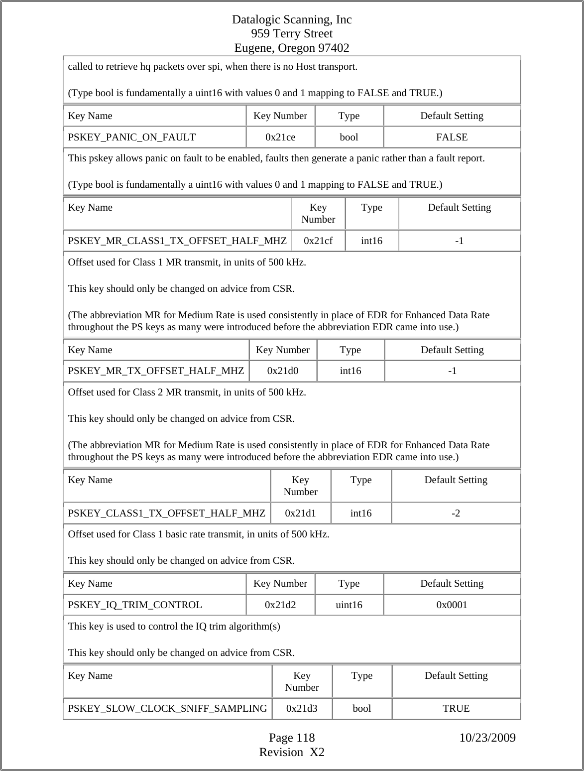
![Datalogic Scanning, Inc 959 Terry Street Eugene, Oregon 97402 Page 119 10/23/2009 Revision X2 This key controls whether extra calibration of the internal low power oscillator is to be performed. This mechanism can potentially improve timing accuracy in low power modes. This key should only be changed on advice from CSR. Key Name Key Number Type Default Setting PSKEY_INITIAL_IQ_LVL 0x21d4 uint16 0x1F1F This key defines the initial IQ level setting for transmission. This key should only be changed on advice from CSR. Key Name Key Number Type Default Setting PSKEY_MIN_CPU_CLOCK 0x21d5 uint16 CPU_SLOW_ANY The firmware tries to save power by reducing the clock rate when the processor is idle ("shallow sleep"). This key controls the minimum clock rate that is permitted during shallow sleep. This key should only be changed on advice from CSR. Incorrect settings can lead to unnecessarily increased power consumption. Key Name Key Number Type Default Setting PSKEY_SLOW_CLOCK_TEMP_HYSTERESIS 0x21d8 uint16 4 The internal low power oscillator (known as the "slow clock") is recalibrated against the accurate clock when the temperature changes. If the temperature change since the last calibration exceeds the value of this key, another calibration is performed. The units of this key are degrees Celsius. Recalibration may be made more sensitive to temperature if the value of PSKEY_SLOW_CLOCK_TEMP_HYSTERESIS_MIN is lower than the value of this key. If a large change in calibration (greater than 200 ppm) is detected, the required temperature change is reduced by steps of 1 degree Celsius until PSKEY_SLOW_CLOCK_TEMP_HYSTERESIS_MIN is reached. If a small change in calibration (less than 100 ppm) is detected, the required temperature change is increased in steps of 1 degree Celsius until PSKEY_SLOW_CLOCK_TEMP_HYSTERESIS is reached. Key Name Key Number Type Default Setting PSKEY_SLOW_CLOCK_CURVE 0x21d9 temperature_calibration[] { -30, 6 }, { 0, 5 }, { 30, 4 }, { 80, 3 } The value consists of a table of pairs of 16-bit signed values, as many pairs as necessary. Each pair is in a similar format to PSKEY_TEMPERATURE_CALIBRATION: the first value is a temperature in degrees Celsius, while in this case the second is the slow clock curve index to be used at that temperature. The index will be interpolated linearly between those settings, but will not be extrapolated beyond the end of the temperature range. The temperatures should increase monotonically. Key Name Key Number Type Default Setting](https://usermanual.wiki/Datalogic-ADC/DLBTMCX.User-manual-RF-module/User-Guide-1192966-Page-119.png)
![Datalogic Scanning, Inc 959 Terry Street Eugene, Oregon 97402 Page 120 10/23/2009 Revision X2 PSKEY_MR_ENABLE_RX_GOLDEN_CURVE_TRIM 0x21da bool TRUE Enables the golden curve RX filter trim code used to optimise the EDR receive performance. (This is for CSR internal use only. If you don't know what it's for, don't play with it.) Key Name Key Number Type Default Setting PSKEY_ANA_TX_IF_FTRIM 0x21dd uint16 8 Setting for the transmitter's TX IF filter present on Elvis r03, JohnPeel r02 and all other BC5 parts that follow these variants. This key should only be changed on advice from CSR. Key Name Key Number Type Default Setting PSKEY_CODEC_MIN_CPU_CLOCK 0x21df uint16 CPU_SLOW_2M The firmware tries to save power by reducing the clock rate when the processor is idle. The clock drives the CPU, PCM, UART, USB, baseband hardware, etc. This is normally called "shallow sleep." Some of the chip's hardware sets a lower limit on how slowly the clock can be run. On chips with an internal audio codec, this key controls what limit codec activity places on the clock speed. The default value should always be safe. It may be possible to reduce this value for reduced power consumption, but the codec function may not operate correctly if run too slow. For more advice, contact CSR. The pskey's acceptable values are: 0 CPU_FAST (full rate) 1 CPU_SLOW_4M (4 MHz) 2 CPU_SLOW_2M (2 MHz) 3 CPU_SLOW_1p024M (1.024 MHz) See also PSKEY_PCM_MIN_CPU_CLOCK. Key Name Key Number Type Default Setting PSKEY_BT_LO_OPTIMISE_FREQS 0x21e0 uint16 0xA0C3 Controls the optimisation of BT LO frequencies across the channels. (This is for CSR internal use only. If you don't know what it's for, don't play with it.) Key Name Key Number Type Default Setting PSKEY_TEMPERATURE_VS_DELTA_INTERNAL_PA_MR 0x21e1 temperature_calibration[] { -40, -2 }, { -10, 0 }, { 50, 0 }, { 60, 1 },](https://usermanual.wiki/Datalogic-ADC/DLBTMCX.User-manual-RF-module/User-Guide-1192966-Page-120.png)