Datalogic ADC DLBTMCX Datalogic Bluetooth Module User Manual DLBTMCX Users Guide 10 23 09
Datalogic ADC, Inc. Datalogic Bluetooth Module DLBTMCX Users Guide 10 23 09
Contents
- 1. Installation to host device
- 2. User manual-RF module
User manual-RF module

Datalogic Scanning, Inc
959 Terry Street
Eugene, Oregon 97402
Page 1 10/23/2009
Revision X2
DLBTM Bluetooth Radio Module Users Guide
Product Description: Datalogic Bluetooth Module
Internal Model Number: DLBTMCX
Datalogic Scanning, Inc
959 Terry Street
Eugene, Oregon 97402
Page 2 10/23/2009
Revision X2
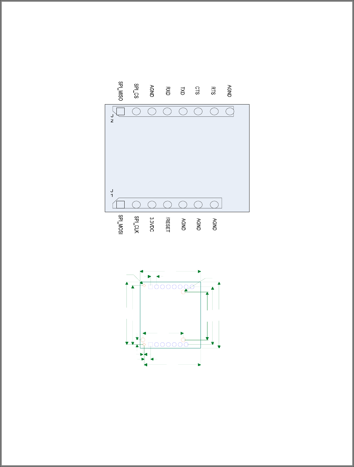
1. Pin Layout
D0.040
D0.071
1.060
1.000
0.080
1.024
0.955
0.110
0.022
0.100
1.122
0.685
0.978
0.810
3X SHIELD CA
N
2X TOOLING

Datalogic Scanning, Inc
959 Terry Street
Eugene, Oregon 97402
Page 3 10/23/2009
Revision X2
2. µP Interface
This design will be HCI only using the H4 protocol for serial communications. The
baud rate will be set at 115.2K.
3. Persistence Storage Keys
The following is a table covering the PS Key addresses and settings for each
location. Please refer to the latest CSR document for updated PS Key settings.
Key Name Key Number Type Default Setting
PSKEY_BDADDR 0x0001 bdaddr 0x00A5A5, 0x5b, 0x0002
The local device's Bluetooth address. This should be unique to this device - allocated during manufacturing.
The type bdaddr can be viewed as a uint16[4] array:
1st uint16: The top 8 bits of the LAP are in the bottom 8
bits of this word. The top 8 bits of this word
must be zero.
2nd uint16: lower 16 bits of the LAP
3rd uint16: The 8 bit UAP is in the bottom 8 bits of this
word. The top 8 bits of this word must be
zero.
4th uint16: 16 bit NAP
For example, the Bluetooth address 123456789abc is encoded as 0078, 9abc, 0056, 1234.
The default value of this key is one of CSR's legal addresses: 00025b00a5a5.
As stated in the Bluetooth specification, LAP values from 9e8b00 up to, and including, 9e8b3f must not be
used as this range is reserved for inquiry access codes (IACs).
Bluetooth module manufacturers must obtain their own block of addresses from the Bluetooth SIG/IEEE. If
CSR's experience is typical, these authorities define the NAP and UAP, allowing manufacturers to set the
24 bit LAP.
Key Name Key Number Type Default Setting
PSKEY_COUNTRYCODE 0x0002 uint16 0
North America and most of Europe use a particular block of 79 radio frequencies for Bluetooth, but not all
countries allow use of these frequencies. Some countries allow the use of different blocks of frequencies.
This key selects the frequency blocks used by these exceptional countries.
Over time most countries are adopting the default 79 frequency block, so the need for this value is
diminishing. At the time of writing this comment it is expected that France, Spain and Japan will use the

Datalogic Scanning, Inc
959 Terry Street
Eugene, Oregon 97402
Page 4 10/23/2009
Revision X2
default frequency block by January 2001.
0 North America and Europe, except ...
1 France
2 Spain
3 Japan
Key Name Key Number Type Default Setting
PSKEY_CLASSOFDEVICE 0x0003 bdcod 0
The local device's default Bluetooth "class of Device" or CoD.
Type bdcod is really a uint32. The class of device is a 24 bit value stored in a uint32; the highest byte must
be zero.
This is the device's default class of device, used when the device boots. The device's class of device may
subsequently be changed by an HCI command. The HCI command does not change the value stored under
this pskey.
The least significant two bits reveal the format of the other 22 bits. The only format currently defined is for
where the two bits are zero:
Bits Content
1 - 0 Format Type (0)
2 - 7 Minor Dev Class (in the context of the Major Dev Class)
8 - 12 Major Dev Class 13 - 23 Major Service Class
At the time of writing this comment the firmware makes no use of this knowledge.
Key Name Key Number Type Default Setting
PSKEY_DEVICE_DRIFT 0x0004 uint16 250
This should hold the local device's radio drift in parts per million. The maximum value allowed by the
Bluetooth specification is 250.
This value is used in LMP_timing_accuracy_res messages sent to peers, as described in Bluetooth version
1.1, LMP specification, section 5.2. It is also used in calculations in low power modes to decide for how
long the radio on a slave device must be turned on in order to resynchronise with a remote master: reducing
the value therefore allows power saving.
The default value is appropriate when BlueCore's internal low power oscillator is in use to maintain timing
during low power modes i.e. for the default setting of PSKEY_DEEP_SLEEP_STATE
(DEEP_SLEEP_ALWAYS, value 1) and PSKEY_DEEP_SLEEP_USE_EXTERNAL_CLOCK (FALSE).
The appropriate values for the various settings of these PSKEYs are given below.
PSKEY_DEEP_SLEEP_STATE = NEVER or INACTIVE (0 or 2): set device drift to 20 ppm to reflect full
Bluetooth clock accuracy.
PSKEY_DEEP_SLEEP_STATE = ALWAYS (1): if PSKEY_DEEP_SLEEP_USE_EXTERNAL_CLOCK
is FALSE, set device drift to 250 ppm (this is the default case). If an external clock is in use, set device drift

Datalogic Scanning, Inc
959 Terry Street
Eugene, Oregon 97402
Page 5 10/23/2009
Revision X2
to the accuracy of that external clock.
PSKEY_DEEP_SLEEP_STATE = ALWAYS_ACCURATE (3):
PSKEY_DEEP_SLEEP_USE_EXTERNAL_CLOCK should be TRUE, so set device drift to the accuracy
of the external clock.
Key Name Key Number Type Default Setting
PSKEY_DEVICE_JITTER 0x0005 uint16 10
This should hold the local device's radio jitter in microseconds. (LMP v1.1, section 5.2.)
This value is used in LMP_timing_accuracy_res messages sent to peers. This is the only use made of this
pskey.
Key Name Key Number Type Default Setting
PSKEY_MAX_ACLS 0x000d uint16 7
The maximum number of concurrent ACL connections to other devices.
Links to remote devices use substantial amounts of RAM to maintain connection state, so this value should
be kept modest. It is advisable to trim this value to match the application, allowing any liberated RAM to
be used elsewhere. The value must be reduced if the chip is running any of the higher layers of the
Bluetooth stack as these take from the common supply of RAM.
Key Name Key Number Type Default Setting
PSKEY_MAX_SCOS 0x000e uint16 3
The maximum number of SCO links to (all) other devices.
The firmware may use a value lower than 3, e.g., because SCO data can only flow over the BlueCore01b's
single PCM interface.
Key Name Key Number Type Default Setting
PSKEY_MAX_REMOTE_MASTERS 0x000f uint16 2
The local device's maximum number of remote piconet masters.
Connecting to multiple remote masters implies the use of scatternets. The current firmware supports one
permanent remote master, plus a second remote master in a temporary state either for performing a remote
name request or in order to connect by a role switch to become a slave.
See the description of PSKEY_ENABLE_MASTERY_WITH_SLAVERY.
Key Name Key
Number Type Default Setting
PSKEY_ENABLE_MASTERY_WITH_SLAVERY 0x0010 bool TRUE
If set TRUE (value 1) then the firmware is configured to support being a master of its own piconet at the
same time as being a slave in one or more other piconets. This implies the use of scatternets.

Datalogic Scanning, Inc
959 Terry Street
Eugene, Oregon 97402
Page 6 10/23/2009
Revision X2
This value is constrained by the value of the pskey PSKEY_MAX_REMOTE_MASTERS.
The "barge-in" connection sequence (an existing master page-scans, it is paged by new a device, then the
new device's link performs a master/slave switch) implies a temporary scatternet. This pskey does not
affect this behaviour.
See the description of PSKEY_MAX_REMOTE_MASTERS.
(Type bool is fundamentally a uint16 with values 0 and 1 mapping to FALSE and TRUE.)
Key Name Key Number Type Default Setting
PSKEY_H_HC_FC_MAX_ACL_PKT_LEN 0x0011 uint16 310
The maximum acceptable length, in bytes, of the data portion of HCI ACL data packets received from the
host. This supports the Host_Buffer_Size HCI command.
It sometimes makes sense to tune this value to obtain better device throughput, but the product of the values
of this key and of PSKEY_H_HC_FC_MAX_ACL_PKTS should be kept constant as this effectively
reserves a block of the device's precious RAM for use by the host.
Key Name Key Number Type Default Setting
PSKEY_H_HC_FC_MAX_SCO_PKT_LEN 0x0012 uint8 64
The maximum acceptable length, in bytes, of the data portion of HCI SCO data packets received from the
host. This supports the Host_Buffer_Size HCI command.
It sometimes makes sense to tune this value to obtain better device throughput, but the product of the values
of this key and of PSKEY_H_HC_FC_MAX_SCO_PKTS should be kept constant as this effectively
reserves a block of the device's precious RAM for use by the host.
This value should be changed only with great care: small values will heavily load the (host and) chip
processor(s), whereas large values will normally increase audio latency.
Key Name Key Number Type Default Setting
PSKEY_H_HC_FC_MAX_ACL_PKTS 0x0013 uint16 10
The maximum number of HCI ACL data packets being sent to air that can be held within the chip at any
time.
This supports the Host_Buffer_Size HCI command.
See the description of PSKEY_H_HC_FC_MAX_ACL_PKT_LEN.
Key Name Key Number Type Default Setting
PSKEY_H_HC_FC_MAX_SCO_PKTS 0x0014 uint16 8
The maximum number of HCI SCO data packets being sent to air that can be held within the chip at any
time.

Datalogic Scanning, Inc
959 Terry Street
Eugene, Oregon 97402
Page 7 10/23/2009
Revision X2
This supports the Host_Buffer_Size HCI command.
See the description of PSKEY_H_HC_FC_MAX_SCO_PKT_LEN.
Key Name Key
Number Type Default Setting
PSKEY_LC_FC_BUFFER_LOW_WATER_MARK 0x0015 lc_fc_lwm 0x0600, 0x0700, 0x0800
A set of values that control the assertion of flow control for data received from air.
The LC determines how much buffer memory has been promised to the host for host to air traffic, then it
adds the safety margins set by this key and compares the result with the available free buffer memory. The
result determines when and how the LC applies flow control for data received from air.
The key holds an array of three values. Each value sets a behaviour threshold, measured in a number of
bytes:
0) Received data is discarded and a NAK is returned.
1) ACL flow control is asserted.
2) L2CAP flow control is asserted.
Buffalo water mark?
Key Name Key Number Type Default Setting
PSKEY_LC_MAX_TX_POWER 0x0017 int16 4
The device's maximum transmit power in dBm.
The firmware ensures the device never speaks more loudly that this value.
The firmware uses the highest value in the power table that is less than or equal to the requested default
power.
Correct operation depends having a valid power table - see PSKEY_LC_POWER_TABLE.
The maximum value depends on the Bluetooth module class:
Class 1: 0 to +20 dBm.
Class 2: -6 to +4 dBm.
Class 3: up to 0 dBm.
Unlike most pskey values, this is a *signed* 16 bit integer.
Key Name Key Number Type Default Setting
PSKEY_TX_GAIN_RAMP 0x001d uint16 0x1810
The device's transmitter gain ramp rate. This controls the power ramp-up at the start of a packet and ramp-
down at end of a packet.
Datalogic Scanning, Inc
959 Terry Street
Eugene, Oregon 97402
Page 8 10/23/2009
Revision X2
For BlueCore01b, the key's range is normally 0x04 to 0x3f. 0x04 gives the slowest ramp rate.
Although the hardware supports values below 0x04, using them will put the software timings so far out that
the module may not work.
The key's value has different effects according to whether the module uses the chip's internal power
amplifier or an external amplifier. (See PSKEY_TXRX_PIO_CONTROL.)
If the internal power amplifier is ramped then the microseconds taken to complete the ramp is
(4*final_value)/ramp_rate.
If an external power amplifier is ramped then the microseconds taken to complete the ramp is
(final_value)/ramp_rate.
In both cases the final_value is taken from PSKEY_LC_POWER_TABLE.
Key value zero has a special behaviour - power is applied without a ramp.
Key Name Key
Number Type Default Setting
PSKEY_LC_FC_POOLS_LOW_WATER_MARK 0x0020 lc_fc_lwm 0x0014, 0x0018, 0x001a
As PSKEY_LC_FC_BUFFER_LOW_WATER_MARK, but describing numbers of available pool memory
blocks.
Key Name Key Number Type Default Setting
PSKEY_LC_DEFAULT_TX_POWER 0x0021 int16 4
The radio's default transmit power, measured in dBm. The chip uses this for page, inquiry and their scan
responses. This is also the power used for new connections.
In 12.X builds the firmware uses the entry in the power table that is closest to this pskey's value. (If the two
closest power tables are equidistant from this key's value then it is indeterminate which power table entry is
used.)
In 13.X and later builds the firmware uses the highest value in the power table that is less than or equal to
the requested default power.
Correct operation depends on the the device having a valid power table - see
PSKEY_LC_POWER_TABLE.
Key Name Key Number Type Default Setting
PSKEY_LC_RSSI_GOLDEN_RANGE 0x0022 uint8 80
The RSSI signal used to measure the signal strength relative to the golden receive range as defined in
section 4.7 of part A of the Bluetooth spec.
Pre 19.x builds:
With the attenuator setting specified in PSKEY_LC_ATTEN_GOLDEN_RANGE_MINIMUM you should
get this RSSI reading for a signal at the bottom of the golden receive range. With the attenuator setting

Datalogic Scanning, Inc
959 Terry Street
Eugene, Oregon 97402
Page 9 10/23/2009
Revision X2
specified in PSKEY_LC_ATTEN_GOLDEN_RANGE_MAXIMUM you should get this RSSI reading for
a signal at the top of the golden receive range.
Taking this signal above 90 can lead to faulty behaviour. If a -60 dBm signal with an attenuation of 1 gives
an RSSI above 90 then leave this setting at 90 as you have a module with good sensitivity. By leaving this
setting at 90 devices you're talking to will be able to lower their transmit power and thus reduce
interference between units.
19.x builds and some 20.x builds:
In builds where PSKEY_LC_ATTEN_GOLDEN_RANGE_MINIMUM and
PSKEY_LC_ATTEN_GOLDEN_RANGE_MAXIMUM have been removed, this should be the RSSI
reading at zero attenuator setting when the received power is at the bottom of the golden range. The top of
the golden range is placed 20 dBm above this.
21.x builds and some 20.x builds:
In builds where PSKEY_PREFERRED_MIN_ATTENUATION exists, with the attenuator setting specified
in PSKEY_PREFERRED_MIN_ATTENUATION, you should get an RSSI value of
PSKEY_LC_RSSI_GOLDEN_RANGE for a signal at the bottom of the golden receive range. The top of
the golden range is placed 20 dBm above this.
Key Name Key
Number Type Default Setting
PSKEY_LC_COMBO_DISABLE_PIO_MASK 0x0028 uint16[] none
A three-element array of uint16s specifying the use of PIO lines to disable non-priority Bluetooth
transmissions:
{ uint16 pio_mask, uint16 pio_invert, uint16 pio_logic }
Bits 0 to 15 of "pio_mask" and "pio_invert" map to PIO0 to PIO15 respectively.
A bit of "pio_mask" set to high enables use of the corresponding PIO pin to disable Bluetooth transmit.
A bit of "pio_invert" set to high indicates that the corresponding PIO pin is active low instead of active
high.
If the "pio_logic" value is zero then any combination of the PIO lines being asserted will disable Bluetooth
transmissions (logical OR), otherwise all of the specified PIO lines must be asserted to disable
transmissions (logical AND).
This PS key is primarily intended for use by IEEE 802.11b combo designs. The signalling is used to disable
Bluetooth transmissions that may degrade 802.11b throughput.
Summary: Non-priority Bluetooth transmissions are disabled in accordance with the following logic:
masked = (PIO ^ pio_invert) & pio_mask
disable = pio_logic ? masked != 0 : masked == pio_mask
Key Name Key
Number Type Default Setting
PSKEY_LC_COMBO_PRIORITY_PIO_MASK 0x0029 uint16[] none

Datalogic Scanning, Inc
959 Terry Street
Eugene, Oregon 97402
Page 10 10/23/2009
Revision X2
A two-element array of uint16s specifying the use of PIO lines to indicate the occurrence of priority
Bluetooth activity (transmit or receive):
{ uint16 pio_mask, uint16 pio_invert }
Bits 0 to 15 of "pio_mask" and "pio_invert" map to PIO0 to PIO15 respectively. A bit of "pio_mask" set to
high enables driving of the corresponding PIO pin to indicate priority activity. A bit of "pio_invert" set to
high indicates that the corresponding PIO pin is active low instead of active high.
Priority operations will typically include, but may not be limited to, the following:
- Inquiry, inquiry scanning and response
- Page, page scanning and response
- Master slave switch
- Park beacons and access windows
- Sniff instants
- Hold instants
- SCO slots
- Broadcast
This PS key is primarily intended for use by IEEE 802.11b combo designs. The signalling is used to disable
802.11b transmissions that may otherwise degrade Bluetooth reliability.
SUMMARY The PIO lines are driven in accordance with the following logic:
PIO = (PIO & ~pio_mask) | ((priority ? pio_mask : 0) ^ pio_invert)
Key Name Key
Number Type Default Setting
PSKEY_LC_COMBO_DOT11_CHANNEL_PIO_BASE 0x002a uint16 none
Set the PIO pins used to obtain the channel number being used by a co-located IEEE 802.11b system. The
value of this pskey is the number of the PIO line used for the least significant bit of the channel number.
The next three PIO lines in sequence are used for the remaining bits of the channel number.
When this pskey is not set, no PIO lines are used for this purpose.
This pskey can also be set to the special value of 13 to indicate that channel usage information will be
provided from an alternative source, e.g. via the HCI Set_AFH_Channel_Classification command.
Values above this are reserved for more esoteric or customer specific coexistence schemes.
The value on the PIO lines decodes to an 802.11b channel number (with centre frequency Fc) as follows:
Number Description
0000b 802.11b inactive
0001b 802.11b channel 1 (Fc = 2.412GHz)
0010b 802.11b channel 2 (Fc = 2.417GHz)
0011b 802.11b channel 3 (Fc = 2.422GHz)
0100b 802.11b channel 4 (Fc = 2.427GHz)
0101b 802.11b channel 5 (Fc = 2.432GHz)
0110b 802.11b channel 6 (Fc = 2.437GHz)
0111b 802.11b channel 7 (Fc = 2.442GHz)
1000b 802.11b channel 8 (Fc = 2.447GHz)
1001b 802.11b channel 9 (Fc = 2.452GHz)

Datalogic Scanning, Inc
959 Terry Street
Eugene, Oregon 97402
Page 11 10/23/2009
Revision X2
1010b 802.11b channel 10 (Fc = 2.457GHz)
1011b 802.11b channel 11 (Fc = 2.462GHz)
1100b 802.11b channel 12 (Fc = 2.467GHz)
1101b 802.11b channel 13 (Fc = 2.472GHz)
1110b 802.11b channel 14 (Fc = 2.484GHz)
1111b Reserved (treated as 0000b)
This pskey is primarily intended for use by IEEE 802.11b combo designs. The signalling is used in
combination with PSKEY_LC_COMBO_DOT11_BLOCK_CHANNELS to disable non-priority Bluetooth
transmissions that may otherwise degrade 802.11b throughput.
Key Name Key
Number Type Default Setting
PSKEY_LC_COMBO_DOT11_BLOCK_CHANNELS 0x002b uint16 11
Set the number of Bluetooth channels to block on either side of an IEEE 802.11b channel centre frequency.
The default value of 11 results in 23 channels being blocked:
Fc - 11, ..., Fc - 1, Fc, Fc + 1, ..., Fc + 11
This pskey is primarily intended for use by IEEE 802.11b combo designs. The signalling is used in
combination with PSKEY_LC_COMBO_DOT11_CHANNEL_PIO_BASE to disable non-priority
Bluetooth transmissions that may otherwise degrade 802.11b throughput.
Key Name Key Number Type Default Setting
PSKEY_LC_MAX_TX_POWER_NO_RSSI 0x002d int8 4
This value is used after a connection is made if it is found that a remote device does not support RSSI
measurements or power control. The transmit power is lowered to correspond to the first entry in
PSKEY_LC_POWER_TABLE whose power in dBm is less than or equal to the value of this pskey.
According to the Bluetooth radio specification, a device may only transmit to a peer which does not support
RSSI or the related LMP messaging using the rules for a class 2 or class 3 device, in other words with a
maximum transmit power of 4 dBm, hence the default value for this pskey. This allows the default transmit
power to be raised above 4 dBm without violating the specification.
Key Name Key
Number Type Default Setting
PSKEY_LC_CONNECTION_RX_WINDOW 0x002e uint16 10
The Bluetooth specification requires that a master or slave be sensitive to timing jitter of transmissions
from the other side up to 10 microseconds while the two devices are connected. The value may be
controlled by this pskey.
Key Name Key
Number Type Default Setting
PSKEY_LC_COMBO_DOT11_TX_PROTECTION_MODE 0x0030 uint16 0
Provides an option to select some Bluetooth packets for protection. The intent is to improve SCO
transmissions in a co-existence scheme.

Datalogic Scanning, Inc
959 Terry Street
Eugene, Oregon 97402
Page 12 10/23/2009
Revision X2
This key can take on three values: 0: All high Priority TX packets are protected - standard setting
Role Switch: Master -> High Priority
Slave-> High Priority Park: Master -> High Priority
Slave -> High Priority Page: High Priority Page Scan: High Priority Inquiry: High Priority Inquiry
Scan:High Priority Fruitbat Test mode:
High Priority LMP traffic Master or Slave:
High Priority SCO: Master or Slave:
High Priority Broadcast:
High Priority Poll:
Master: -> High Priority Start of Sniff:
Master -> High Priority
1: SCO TX packets are not protected but other priority TX packets are 2: No TX packets are
protected.
Although some packets are not protected this key does not affect whether they are transmitted or not.
Key Name Key
Number Type Default Setting
PSKEY_LC_ENHANCED_POWER_TABLE 0x0031 enhanced_power_setting[] {{36, 0, 0, 5, 0},
{38, 0, 0, 5, 0}, -
16}, {{32, 0, 0, 4,
0}, {34, 0, 0, 4, 0},
-12}, {{34, 0, 0, 3,
0}, {36, 0, 0, 3, 0},
-8}, {{37, 0, 0, 2,
0}, {39, 0, 0, 2, 0},
-4}, {{41, 0, 0, 1,
0}, {43, 0, 0, 1, 0},
0}, {{46, 0, 0, 0,
0}, {48, 0, 0, 0, 0},
4}
This table is used in firmware which supports the Enhanced Data Rate specification. Any values set in
PSKEY_LC_POWER_TABLE are ignored; the two tables are mutually exclusive.
The chip has an internal power amplifier (PA); this has a gain control. Some module designs also have an
external PA; this may have a gain control. Additional, the chip has a pre-amplifier (TX-PRE) which also
has a gain control.
The power table stored under this pskey provides a mapping between the three PAs' gain settings and the
corresponding transmit power. This table is basis of all of the firmware's transmit power control: LMP
dynamic power control, PSKEY_LC_MAX_TX_POWER, PSKEY_LC_DEFAULT_TX_POWER, etc.
Every module design must have an appropriate power table. The default value suits the CSR Casira
hardware; this is not suitable for other module designs.
The pskey's value is an array of "power_setting" types. The array's length is not fixed; typically an array is
between 1 and 10 elements long.
Each array element (of type "power_setting") holds seven bytes within five uint16s:

Datalogic Scanning, Inc
959 Terry Street
Eugene, Oregon 97402
Page 13 10/23/2009
Revision X2
The first and second word control basic data rate operation.
1st uint16, lower byte: uint8 external_pa for basic rate
1st uint16, upper byte: uint8 internal_pa for basic rate
2nd uint16: bit 0 controls class 1 and class 2 operation
with a dynamically switchable external PA
(see below). Bits 4 to 6 control the tx_pa_attn
value used BC5 and later chips, and must be zero
on chips earlier chips. Other bits must be zero.
The third and fourth words control enhanced data rate operation. Its form mirrors that of the first and
second words.
3rd uint16, lower byte: uint8 external_pa for enhanced rate
3rd uint16, upper byte: uint8 internal_pa for enhanced rate
On chips prior to BC5, this should be
fixed. Currently the value 63 is
recommended.
4th uint16, lower byte: bit 0 inhibits user of this power with
enhanced data rate (see below). Bits
4 to 6 control the tx_pa_attn value
used on chips which have a TX PA
attenuator, and should be zero
on chips which do not. Other bits must
be zero.
4th uint16, upper byte: uint8 TX-PRE level for enhanced rate
Typically this is 64 greater than the
internal_pa for basic rate (upper byte
of first word). On BC5 and later chips
this value must be zero.
The fifth word specifies the output power common to both data rates.
5th uint16, upper byte: int8 tx dBm
5th uint16, lower byte: set to zero.
If the bottom bit of the second word is set ('EXT PA' bit), operation with dynamically switchable external
PA is assumed.
For any transmission with 'EXT PA' bit set, whether basic rate or enhanced data rate, class 1 logic will be
assumed. The external PA will be used and the AUX_DAC will be set to the lower byte of the first word or
the lower byte of the third word of the entry as appropriate. In addition,
PSKEY_TRANSMIT_OFFSET_CLASS1 and PSKEY_TX_PRE_LVL_CLASS1 are used in place of
PSKEY_TX_OFFSET_HALF_MHZ (or PSKEY_TRANSMIT_OFFSET) and PSKEY_TX_PRE_LVL.
If entries are present in the power table with the 'EXT PA' bit set, then class 2 operation is assumed for
transmissions in which the 'EXT PA' bit is clear. PIO1 and the AUX_DAC will be pulled low during
transmit. In addition, the PIO given by PSKEY_TX_AVOID_PA_CLASS1_PIO will be asserted to
indicate such a transmission.
When no entries in the power table have the `EXT PA' bit set, PSKEY_TX_AVOID_PA_CLASS1_PIO is
not used and the settings given by other PS keys such as PSKEY_TXRX_PIO_CONTROL are applied

Datalogic Scanning, Inc
959 Terry Street
Eugene, Oregon 97402
Page 14 10/23/2009
Revision X2
directly.
For example, power_setting { 0x0d11, 0, 0x3f11, 0x4d00, 0xf800 } specifies:
To get power output -8 dBm for basic data rate (1 Mbps) use
internal amp 13, external amp 17.
To get power output -8 dBm, for enhanced data rate (2 or 3 Mbps) use
internal amp 63, external amp 17, TX-PRE amp 0x4d.
A power table is a list of these entries. The entries must be in ascending order of transmit power.
If the table contains only one entry (five uint16s) then the firmware always uses these settings.
The firmware responds to peer requests to increase/decrease transmit power by stepping up and down this
table. The Bluetooth spec. constrains the sizes and number of steps, which in turn bounds the size and
content of the power table.
In EDR operation, if the bottom bit of the fourth word is set, the power is marked as unavailable for EDR
transmissions. Depending on the setting of BCCMD Limit_EDR_Power, the chip will either change the
packet type table to basic rate; or refuse peer power control requests which request it to exceed the
maximum allowed EDR power. If PSKEY_LC_DEFAULT_TX_POWER is greater than the maximum
allowed EDR power, BlueCore will refuse to enter use EDR until the peer requests it to decrement its
power sufficiently, after which it will attempt to change the packet type table to use EDR.
Note that, although this table is not used directly for the CSR-specific radiotest command set, two features
of this table are used to determine transmitter behaviour in radiotest mode:
- The first entry in the table is used to determine the fixed
internal_pa setting for EDR operation. The internal_pa
value passed to the radiotest command in EDR mode (indicated
by packet types of 16 or over) is used to control the TX-PRE
level in the manner described above.
- The presence of an entry with the `EXT PA' bit set is
necessary before radiotest will use the class1 logic to
transmit. However, in addition, the external_pa value
passed to radiotest (the upper byte of the transmitter gain)
must be non-zero for class 1 mode to be used.
See PSKEY_TXRX_PIO_CONTROL to see how the chip's AUX_DAC pin controls an external PA.
The current Casira design has a fixed-gain external PA; its AUX_DAC is not connected to the PA. The
default power table thus always has external_pa set to zero.
See PSKEY_LC_POWER_TABLE, PSKEY_LC_MAX_TX_POWER,
PSKEY_LC_DEFAULT_TX_POWER, PSKEY_LOCAL_SUPPORTED_FEATURES,
PSKEY_TXRX_PIO_CONTROL, PSKEY_TX_AVOID_PA_CLASS1_PIO,
PSKEY_TRANSMIT_OFFSET_CLASS1, PSKEY_TX_PRE_LVL_CLASS1,
PSKEY_TRANSMIT_OFFSET_HALF_MHZ, PSKEY_TRANSMIT_OFFSET, and
PSKEY_TX_PRE_LVL
Key Name Key
Number Type Default Setting

Datalogic Scanning, Inc
959 Terry Street
Eugene, Oregon 97402
Page 15 10/23/2009
Revision X2
PSKEY_LC_WIDEBAND_RSSI_CONFIG 0x0032 wideband_rssi_config 113, 98, 9, 50
Hardware from BlueCore3-Ext has a facility for wideband RSSI measurement. This key is used to
configure the settings.
It consists of four 16-bit words.
The first word is the value of the wideband RSSI reading above which the RSSI high target should be
reduced.
The second word is the value of the wideband RSSI readinb below which the RSSI high target should be
increased.
THe third word is the step used when changing the RSSI high target.
The fourth word is the minimum allowed value of the RSSI high target. The maximum value is
PSKEY_RSSI_HI_TARGET, or PSKEY_LC_RSSI_GOLDEN_RANGE on builds without
PSKEY_RSSI_HI_TARGET.
Key Name Key
Number Type Default Setting
PSKEY_LC_COMBO_DOT11_PRIORITY_LEAD 0x0033 uint16 50
This key is used only when we are using the Intel Phase 2 COEX scheme. This key defines the value for
T_priority_lead which is the time between us raising the BT_Priority signal and the packet header
beggining.
This key might be removed on later builds once a good value has been found.
Key Name Key Number Type Default Setting
PSKEY_BT_CLOCK_INIT 0x0034 uint32 0UL
The value to which the Bluetooth clock will be initialised at boot. The value 0 is standard; the only likely
reason to alter this is for debugging non-CSR devices known to encounter problems at certain clock values.
(Historical note: before this key was introduced, CSR devices initialised their Bluetooth clocks from the
lower 28 bits of the Bluetooth address, i.e. the lower 4 bits of the UAP followed by the LAP.)
Key Name Key
Number Type Default Setting
PSKEY_LC_COMBO_DOT11_FREQ_PIO_MASK 0x0035 uint16 0
This key is used only when we are using some of the more advanced coexistence schemes. This key defines
a PIO mask that shall be used to indicate when we are overlapping in frequency (between the Bluetooth
device and the WLAN device).
Key Name Key Number Type Default Setting
PSKEY_CONDITIONAL_SCAN_ENABLE 0x0036 bool FALSE
If set TRUE (value 1), then the firmware will rapidly scan the Bluetooth band on the first slot pair of a page
or inquiry scan, looking for any transmissions in the band. If it finds none, it will not listen for the

Datalogic Scanning, Inc
959 Terry Street
Eugene, Oregon 97402
Page 16 10/23/2009
Revision X2
remaining scan window. The intention is to save power when there are no other devices nearby.
Key Name Key
Number Type Default Setting
PSKEY_CONDITIONAL_SCAN_THRESHOLD 0x0037 uint16 0x0060
RSSI threshold for energy detection. Pre-BC5 two bytes are used. The lowest byte is the narrow band RSSI
threshold. This is in LSB for the ADC, not in mV. The upper byte is the number of LSB above baseline for
the wide band RSSI. For BC5/6 a single 10 bit value is used, again considered as ADC levels and not
directly calibrated in mV.
Key Name Key Number Type Default Setting
PSKEY_TX_MR_MOD_DELAY 0x0038 uint8 0x59
Trim timing for EDR transmit Mod delay for TX
Key Name Key Number Type Default Setting
PSKEY_RX_MR_SYNC_TIMING 0x0039 uint16 0x463F
Trim timing for EDR sync
Key Name Key Number Type Default Setting
PSKEY_RX_MR_SYNC_CONFIG 0x003a uint16 0x0024
Acceptable correlation quality of EDR
Key Name Key Number Type Default Setting
PSKEY_LC_LOST_SYNC_SLOTS 0x003b uint16 0
In low power modes, a device will consider it has lost synchronisation with its peer if it fails to receive an
expected transmission in one of the following circumstances:
- In sniff mode as a slave, during any sniff window when nothing
is received.
- In sniff mode as a master, during any sniff window when the slave
has been sent a POLL or a data packet and no reply has been
received.
- In park mode as a slave, when no transmission is received on any
park beacon in a train.
This key specifies a value in baseband slots (units of 625 us) which must elapse since the last packet
received from the remote device before the logic described above applies.
Key Name Key Number Type Default Setting
PSKEY_RX_MR_SAMP_CONFIG 0x003c uint16 0x0426
Acceptable correlation quality of EDR
Key Name Key Number Type Default Setting

Datalogic Scanning, Inc
959 Terry Street
Eugene, Oregon 97402
Page 17 10/23/2009
Revision X2
PSKEY_AGC_HYST_LEVELS 0x003d agc_hyst_config 0x8, 0x6, 0xb, 0x9
BlueCore contains an automatic gain control algorithm which attempts to maintain a reasonable signal level
by adding and removing various sources of attenuation. This key controls the signal strength at which these
sources are added and removed. It should not be altered except on advice from CSR.
Key Name Key Number Type Default Setting
PSKEY_NO_CAL_ON_BOOT 0x0042 bool FALSE
Setting this key to TRUE causes the LC not to calibrate the radio at boot time. This means that the radio
will not work until the key is set to false and the chip is rebooted. This key is intend to allow the use of a
bootmode where the radio is disabled. (For details on bootmodes, see the document "Understanding and
Using Bootmodes", document number CS-101528-AN (previously numbered as bcore-an-019P) on the
CSR support website).
(Type bool is fundamentally a uint16 with values 0 and 1 mapping to FALSE and TRUE.)
Key Name Key Number Type Default Setting
PSKEY_RSSI_HI_TARGET 0x0043 uint8 80
This key controls a parameter used by BlueCore's automatic gain control (AGC) algorithm. It should not be
changed except on advice from CSR.
Key Name Key
Number Type Default Setting
PSKEY_PREFERRED_MIN_ATTENUATION 0x0044 uint8 4
See the description of PSKEY_LC_RSSI_GOLDEN_RANGE for 21.x builds.
Key Name Key
Number Type Default Setting
PSKEY_LC_COMBO_DOT11_PRIORITY_OVERRIDE 0x0045 bool FALSE
If this key is set to TRUE then all Bluetooth activity will be treated as high priority.
See also PSKEY_LC_COMBO_PRIORITY_PIO_MASK.
Key Name Key Number Type Default Setting
PSKEY_LC_MULTISLOT_HOLDOFF 0x0047 TIME 300 * MILLISECOND
The BT 1.2 specification recommends that in low power modes the master should use single slot packets to
help the slave resynchronise. This would be at the sniff instant or at the end of a hold.
However, a too literal following of this rule can cause bandwidth problems with short sniff intervals as the
master will use single slot packets frequently.
Clearly, for really short sniff intervals, the slave should find it not signficantly harder to resynchronise than
it does in active mode and in active mode multi-slot packet are encouraged.
So, a more lax interpretation, but still within the spirit of the spec, would be to use the single slot behaviour
only when the sniff interval or hold period has been long enough that the slave might need some help

Datalogic Scanning, Inc
959 Terry Street
Eugene, Oregon 97402
Page 18 10/23/2009
Revision X2
resynchronising.
This PS key holds a time indicating how long the master has to have not heard from the slave before it will
start using single slot packets to help the slave resynchronise.
One way to calculate a good time is to know that in low power modes, the error between the master and
slave's clock can grow at up to 500 ppm (since each device's clock is allowed to be upto 250 ppm from
nominal). The slave is likely to get problems once it has to keep its correlator open for a full slot. A full slot
is 625 us which means an maximum error between the two links of 312.5 us (as the sign of the error is also
unknown). At 500 ppm it will take about 600 ms to reach this level. This suggests that the value of this key
should be well below 600 ms.
Key Name Key
Number Type Default Setting
PSKEY_LC_COMBO_DOT11_PIOS_ENABLE 0x004a bool TRUE
This key controls whether the PIO signalling lines defined in
PSKEY_LC_COMBO_PRIORITY_PIO_MASK will be active at boot up. The BCCMD
COEX_PRIORITY_PIOS_ON can be used to control the setting dynamically.
This key is supported only on versions of firmware that support the associated BCCMD. On firmware
versions that don't support the BCCMD, the value of PSKEY_LC_COMBO_PRIORITY_PIO_MASK can
be altered to provide the same effect as this key.
Key Name Key Number Type Default Setting
PSKEY_LC_ENABLE_LATE_SAMPLE 0x004b bool TRUE
This key controls when the LC should sample if data is available for transmission. If enabled the LC
samples as late as possible for data being available.
Key Name Key Number Type Default Setting
PSKEY_LC_CLOCKS_CONFIG 0x004f uint16 0
Miscellaneous configuration of hardware clocks for Bluetooth.
This key should only be changed on advice from CSR.
Key Name Key
Number Type Default Setting
PSKEY_LC_COMBO_DOT11_ESCO_RTX_PRIORITY 0x0050 bool FALSE
If this key is set to TRUE, the BlueCore's co-existence interface will treat eSCO retransmissions as being
low priority. (Note the priority of the initial transmission of the eSCO data remains high).
Key Name Key Number Type Default Setting
PSKEY_EDR_SWITCH_MODE 0x0051 edr_switch_mode HIGH_TO_LOW
The EDR_SWITCH_MODE will be used to describe the assertion method for the
EDR_SWITCH_MODE_PIO and will be used to setup the driving method, Low To High or High To Low.
Key Name Key Number Type Default Setting

Datalogic Scanning, Inc
959 Terry Street
Eugene, Oregon 97402
Page 19 10/23/2009
Revision X2
PSKEY_EDR_MODE_SWITCH_PIO 0x0052 uint16 none
This key will assert the PIO line specified, 0-15 if present, if the key is not present it will become a zero
length key with an attempt to read it failing, this will fail the psget method and disable use of this key. If
the pskey is defined but the value is 0xffff, out of bounds, then the key will not setup a pio line. The use of
this pskey is intended to be the mode select line for an EDR power amp, the assertion method will be in
PSKEY EDR_SWITCH_MODE,this will be either high to low or low to high.
If a pio line is required for tx enablement then you should use the PSKEY_TXRX_PIO_CONTROL, pio
pin 1 which asserts when we are transmitting.
Key Name Key
Number Type Default Setting
PSKEY_LC_ENABLE_WATCHDOG_FAULT 0x0053 bool FALSE
This is a debugging option; CSR internal use only.
Key Name Key
Number Type Default Setting
PSKEY_LC_COMBO_DOT11_SIGNAL_BANDSCAN 0x0055 bool FALSE
This key controls BlueCore's co-existence signalling of AFH band scans using the co-existence signalling
PIOs. When this key is set, BlueCore to signal band scans as long receives.
PSKEY_LC_COMBO_DOT11_ABORT_BANDSCAN controls whether BlueCore responds to abort
signals for band scans.
This key only applies to the Unity-3 wire co-existence scheme.
Key Name Key
Number Type Default Setting
PSKEY_LC_COMBO_DOT11_ABORT_BANDSCAN 0x0056 bool FALSE
This key controls BlueCore's response to co-existence signalling during AFH band scans. When this key is
set, BlueCore will abort a band scan if the wifi device requests this during the time after BlueCore signals
its intention to receive but before the band scan starts. BlueCore will not abort a scan in progress after this.
This key has no effect if BlueCore has not been configured to signal band scans on the co-existence PIOs
by setting PSKEY_LC_COMBO_DOT11_SIGNAL_BANDSCAN.
This key only applies to the Unity-3 wire co-existence scheme.
Key Name Key
Number Type Default Setting
PSKEY_LC_PEER_POWER_INCR_PERIOD 0x0057 TIME 100000
The period, measured in microseconds, between attempts to increment the peer's transmit power.
Setting this to zero disables the periodic checks. This means the local device will not send messages
concerning power management or channel quality driven data rate to the remote device. This pskey is

Datalogic Scanning, Inc
959 Terry Street
Eugene, Oregon 97402
Page 20 10/23/2009
Revision X2
paired with decrement peer power period.
(Type TIME is fundamentally a uint32. Value SECOND is 1000000. Value MILLISECOND is 1000.)
Key Name Key
Number Type Default Setting
PSKEY_LC_PEER_POWER_DECR_PERIOD 0x0058 TIME 1 * SECOND
The period, measured in microseconds, between attempts to decrement the peer's transmit power, the same
interval is used for measurements of channel quality to support LMP channel quality driven data rate
messages.
This pskey is paired with the respective increment peer power period. This key will have a minimum value
of 100ms, how ever it will be disabled if the increment peer power period is set to 0. This means the local
device will not send messages concerning peer power management.
(Type TIME is fundamentally a uint32. Value SECOND is 1000000. Value MILLISECOND is 1000.)
Key Name Key
Number Type Default Setting
PSKEY_LC_COMBO_DOT11_PULL_DIRECTION 0x005b uint16 0x0000
This key configures the input lines on some BlueCore chips associated with 802.11 coexistence interfaces.
For each bit set in this PSKEY that corresponds to a coexistence input signal, the corresponding PIO will
be configured with a weak pull-up, otherwise it will be left as a weak pull-down (the default).
Key Name Key
Number Type Default Setting
PSKEY_LC_COMBO_DOT11_PERIODIC_PIO_MASK 0x005c uint16[] none
A two-element array of uint16s specifying the use of PIO lines to signal the timing of very important
periodic activity between BlueCore and a collocated IEEE 802.11 radio:
{ uint16 pio_mask, uint16 pio_invert }
Bits 0 to 15 of "pio_mask" and "pio_invert" map to PIO0 to PIO15 respectively. A bit of "pio_mask" set to
high enables use of the corresponding PIO pin to signal periodic activity. A bit of "pio_invert" set to high
indicates that the corresponding PIO pin is active low instead of active high.
PSKEY_LC_COMBO_DOT11_PERIODIC_PIO_MODE is used to control how the specified PIOs are
used.
Key Name Key
Number Type Default Setting
PSKEY_LC_COMBO_DOT11_PERIODIC_PIO_MODE 0x005d uint16 COEXISTENCE_BT_OUTPUT
Set the default usage of the periodic PIO coexistence lines specified by
PSKEY_LC_COMBO_DOT11_PERIODIC_PIO_MASK (if any).
The pskey's acceptable values are:

Datalogic Scanning, Inc
959 Terry Street
Eugene, Oregon 97402
Page 21 10/23/2009
Revision X2
0 COEXISTENCE_NONE PIO is not used (high impedance)
1 COEXISTENCE_BT_OUTPUT PIO is asserted for the duration of
SCO and eSCO reserved slots
With current firmware builds this should be left at its default of COEXISTENCE_BT_OUTPUT, with the
functionality enabled or disabled by modifying PSKEY_LC_COMBO_DOT11_PERIODIC_PIO_MASK as
appropriate.
Note: For correct operation of COEXISTENCE_BT_OUTPUT it is necessary to also set
PSKEY_LC_COMBO_DOT11_ESCO_RTX_PRIORITY = TRUE.
Key Name Key Number Type Default Setting
PSKEY_LC_COMBO_DOT11_T1 0x005e uint16 150
This PSKEY configures the value of T1
Key Name Key Number Type Default Setting
PSKEY_LC_COMBO_DOT11_T2 0x005f uint16 17
This PSKEY configures the value of T2
Key Name Key
Number Type Default Setting
PSKEY_LC_HIGH_PRIORITY_SNIFF_TIMEOUTS 0x0060 bool FALSE
This key affects the algorithm that selects the value of Dsniff when negotiating sniff mode for an ACL
connection. If no value is set or the value is FALSE, sniff timeout slots will not be included in the
calculation unless the quality of service for the connection is "guaranteed". If the value is TRUE, sniff
timeout slots will always be taken into account: this means that extra spacing is left in the air time schedule,
where possible, to allow for a transmission to a slave during one iteration of the timeout slots.
This key has no direct effect on the real-time scheduling of links in sniff mode, so it does not necessarily
cause a master to address the slave in the timeout slots. A QoS setting of "guaranteed" for an ACL
connection causes sniff timeout slots to be treated as high priority by the real-time scheduler; however, that
should be used with caution as it can have a significant effect on the bandwidth available for other links.
(Type bool is fundamentally a uint16 with values 0 and 1 mapping to FALSE and TRUE.)
Key Name Key Number Type Default Setting
PSKEY_FREE_KEY_PIGEON_HOLE 0x00c9 uint16 0
A bitfield indicating which link keys are stored. A 1 in this mask indicates that the corresponding link key
is occupied.
Freaky pigeon hole?
Key Name Key
Number Type Default Setting
PSKEY_LINK_KEY_BD_ADDR0 0x00ca LM_LINK_KEY_BD_ADDR_T none
Datalogic Scanning, Inc
959 Terry Street
Eugene, Oregon 97402
Page 22 10/23/2009
Revision X2
A Bluetooth address and its corresponding link key.
1st uint16: top 8 bits of the LAP in the lower byte
2nd uint16: lower 16 bits of the LAP
3rd uint16: 16 bit UAP
4th uint16: 8 bit NAP in the lower byte Link key is 8 words, following the 4-word BDADDR. The link
key is stored little-endian, so MSW is at position 11, LSW at position 4. Occupied keys should appear in
PSKEY_FREE_KEY_PIGEON_HOLE
Key Name Key
Number Type Default Setting
PSKEY_LINK_KEY_BD_ADDR1 0x00cb LM_LINK_KEY_BD_ADDR_T none
A Bluetooth address and its corresponding link key. See description for PSKEY_LINK_KEY_BD_ADDR0
Key Name Key
Number Type Default Setting
PSKEY_LINK_KEY_BD_ADDR2 0x00cc LM_LINK_KEY_BD_ADDR_T none
A Bluetooth address and its corresponding link key. See description for PSKEY_LINK_KEY_BD_ADDR0
Key Name Key
Number Type Default Setting
PSKEY_LINK_KEY_BD_ADDR3 0x00cd LM_LINK_KEY_BD_ADDR_T none
A Bluetooth address and its corresponding link key. See description for PSKEY_LINK_KEY_BD_ADDR0
Key Name Key
Number Type Default Setting
PSKEY_LINK_KEY_BD_ADDR4 0x00ce LM_LINK_KEY_BD_ADDR_T none
A Bluetooth address and its corresponding link key. See description for PSKEY_LINK_KEY_BD_ADDR0
Key Name Key
Number Type Default Setting
PSKEY_LINK_KEY_BD_ADDR5 0x00cf LM_LINK_KEY_BD_ADDR_T none
A Bluetooth address and its corresponding link key. See description for PSKEY_LINK_KEY_BD_ADDR0
Key Name Key
Number Type Default Setting
PSKEY_LINK_KEY_BD_ADDR6 0x00d0 LM_LINK_KEY_BD_ADDR_T none
A Bluetooth address and its corresponding link key. See description for PSKEY_LINK_KEY_BD_ADDR0
Key Name Key
Number Type Default Setting
PSKEY_LINK_KEY_BD_ADDR7 0x00d1 LM_LINK_KEY_BD_ADDR_T none
A Bluetooth address and its corresponding link key. See description for PSKEY_LINK_KEY_BD_ADDR0
Key Name Key Type Default Setting
Datalogic Scanning, Inc
959 Terry Street
Eugene, Oregon 97402
Page 23 10/23/2009
Revision X2
Number
PSKEY_LINK_KEY_BD_ADDR8 0x00d2 LM_LINK_KEY_BD_ADDR_T none
A Bluetooth address and its corresponding link key. See description for PSKEY_LINK_KEY_BD_ADDR0
Key Name Key
Number Type Default Setting
PSKEY_LINK_KEY_BD_ADDR9 0x00d3 LM_LINK_KEY_BD_ADDR_T none
A Bluetooth address and its corresponding link key. See description for PSKEY_LINK_KEY_BD_ADDR0
Key Name Key
Number Type Default Setting
PSKEY_LINK_KEY_BD_ADDR10 0x00d4 LM_LINK_KEY_BD_ADDR_T none
A Bluetooth address and its corresponding link key. See description for PSKEY_LINK_KEY_BD_ADDR0
Key Name Key
Number Type Default Setting
PSKEY_LINK_KEY_BD_ADDR11 0x00d5 LM_LINK_KEY_BD_ADDR_T none
A Bluetooth address and its corresponding link key. See description for PSKEY_LINK_KEY_BD_ADDR0
Key Name Key
Number Type Default Setting
PSKEY_LINK_KEY_BD_ADDR12 0x00d6 LM_LINK_KEY_BD_ADDR_T none
A Bluetooth address and its corresponding link key. See description for PSKEY_LINK_KEY_BD_ADDR0
Key Name Key
Number Type Default Setting
PSKEY_LINK_KEY_BD_ADDR13 0x00d7 LM_LINK_KEY_BD_ADDR_T none
A Bluetooth address and its corresponding link key. See description for PSKEY_LINK_KEY_BD_ADDR0
Key Name Key
Number Type Default Setting
PSKEY_LINK_KEY_BD_ADDR14 0x00d8 LM_LINK_KEY_BD_ADDR_T none
A Bluetooth address and its corresponding link key. See description for PSKEY_LINK_KEY_BD_ADDR0
Key Name Key
Number Type Default Setting
PSKEY_LINK_KEY_BD_ADDR15 0x00d9 LM_LINK_KEY_BD_ADDR_T none
A Bluetooth address and its corresponding link key. See description for PSKEY_LINK_KEY_BD_ADDR0
Key Name Key Number Type Default Setting
PSKEY_ENC_KEY_LMIN 0x00da uint16 1

Datalogic Scanning, Inc
959 Terry Street
Eugene, Oregon 97402
Page 24 10/23/2009
Revision X2
The minimum length of an encryption key in bytes. Range 1->16. A value of 1 implies a minimum
encryption key length of 8 bits, etc.
(BT specification 1.1, Section 14.3.1 p159: 1<=Lmax<=16. Section 14.3.3, p161, 3rd paragraph: max key
size between one and sixteen. Section 14.3.5, p166: table does not contain key of length zero.)
See PSKEY_ENC_KEY_LMAX.
Key Name Key Number Type Default Setting
PSKEY_ENC_KEY_LMAX 0x00db uint16 16
The maximum length of an encryption key in bytes.
Range 1->16. A value of 1 implies a maximum encryption key length of 8 bits, etc.
(BT specification 1.1, Section 14.3.1 p159: 1<=Lmax<=16. Section 14.3.3, p161, 3rd paragraph: max key
size between one and sixteen. Section 14.3.5, p166: table does not contain key of length zero.)
UK Government restrictions require CSR to limit the maximum effective key length to less than 16 for
some firmware builds.
See PSKEY_ENC_KEY_LMIN.
Key Name Key
Number Type Default Setting
PSKEY_LOCAL_SUPPORTED_FEATURES 0x00ef uint16[] 0xffff, 0xfe8f, 0xff9b,
0x8359
A 4 element array of uint16s holding a bitfield that describes the features supported by the local device.
Coding matches the "coding of features" section in the LMP specification. The first byte of the coding of
features is held in the lower byte of the first uint16, etc.
The key's default value gives the firmware's capabilities. Switching a bit from 0 to 1 does not magically
create a missing capability.
This key configures the local LM. If a feature is marked as provided by the default value, then clearing the
key's bit turns off the corresponding functionality. For example, setting the Encryption bit to zero stops the
local device supporting encryption.
The three "flow control lag" bits should be left at zero.
The order in 1.2 of the spec is as follows.
First word, low to high (X => turned on in default config; (X) => turned on if supported by hardware;)
On Bit Feature
X 0 3-slot packets
X 1 5-slot packets
X 2 Encryption
X 3 Slot offset
X 4 Timing accuracy

Datalogic Scanning, Inc
959 Terry Street
Eugene, Oregon 97402
Page 25 10/23/2009
Revision X2
X 5 Master/slave switch
X 6 Hold mode
X 7 Sniff mode
X 8 Park mode
X 9 Power control requests
X 10 Data rate driven by channel quality
X 11 SCO link
X 12 HV2 packets
X 13 HV3 packets
X 14 mu-law voice encoding
X 15 A-law voice encoding
Second word
X 0 CVSD
X 1 Paging scheme
X 2 Power control
X 3 Transparent SCO data
4 }
5 } L2CAP flow control lag (our default = 0)
6 }
[1.2 features from this point]
X 7 Broadcast encryption
8 Reserved (Scatter mode)
(X) 9 Enhanced Data Rate ACL 2 Mbps mode
(X) 10 Enhanced Data Rate ACL 3 Mbps mode
X 11 Enhanced inquiry scan
X 12 Interlaced inquiry scan
X 13 Interlaced page scan
X 14 RSSI with inquiry results
(X) 15 Extended SCO link --- EV3 packets
Third word
(X) 0 Extended SCO link --- EV4 packets
(X) 1 Extended SCO link --- EV5 packets
2 Reserved (Absence masks)
X 3 AFH capable slave
X 4 AFH classification slave
5 Reserved (Alias authentication)
6 Reserved (Anonymity mode)
(X) 7 3-slot Enhanced Data Rate ACL packets
(X) 8 5-slot Enhanced Data Rate ACL packets
X 9 Sniff Subrating
X 10 Pause Encryption
X 11 AFH capable master
X 12 AFH classification master
(X) 13 Enhanced Data Rate eSCO 2 Mbps mode
(X) 14 Enhanced Data Rate eSCO 3 Mbps mode
(X) 15 3-slot Enhanced Data Rate eSCO packets
Fourth word
X 0 Extended Inquiry Response
1-2 Reserved
X 3 Secure Simple Pairing
X 4 Encapsulated PDU

Datalogic Scanning, Inc
959 Terry Street
Eugene, Oregon 97402
Page 26 10/23/2009
Revision X2
5 Erroneous Data Reporting
X 6 Non-flushable Packet Boundary Flag
7 Reserved
X 8 Link Supervision Timeout Changed Event
X 9 Inquiry Response TX Power Level
10-14 Reserved
X 15 Extended features [i.e. highest bit in feature mask]
Key Name Key Number Type Default Setting
PSKEY_LM_USE_UNIT_KEY 0x00f0 bool FALSE
Combination or unit keys can be used for authentication depending on devices' storage capacity. This key is
set to TRUE if unit keys are to be used by default instead of combination keys.
(Type bool is fundamentally a uint16 with values 0 and 1 mapping to FALSE and TRUE.)
Key Name Key Number Type Default Setting
PSKEY_HCI_NOP_DISABLE 0x00f2 bool FALSE
By default the BlueCore firmware sends an HCI command_status(NOP) event to the host shortly after
booting. Although this is clearly allowed by the HCI specification it is known to crash some host stacks.
This pskey provides a simple workaround: if this key is TRUE then this boot-time event is not emitted.
(Type bool is fundamentally a uint16 with values 0 and 1 mapping to FALSE and TRUE.)
Key Name Key Number Type Default Setting
PSKEY_LM_MAX_EVENT_FILTERS 0x00f4 uint8 5
Each time an event filter is added, it consumes valuable RAM resources. To limit the maximum amount of
RAM event filters can take we limit the maximum number of event filters.
Key Name Key
Number Type Default Setting
PSKEY_LM_TEST_SEND_ACCEPTED_TWICE 0x00f6 bool FALSE
The Bluetooth 1.1 specification does not ensure reliability of LMP traffic in test mode, since it does not
differentiate test packets (which are unreliable) from LMP packets at the baseband level. This can lead to
loss of LMP messages.
If this key is set to TRUE, a slave in test mode will send the LMP_Accepted reply to a test control message
twice. This increases the likelihood that the message will be received by the tester. (It does not guarantee it
because, since the link manager does not operate in real time, there may be test messages in between the
transmissions.)
(Type bool is fundamentally a uint16 with values 0 and 1 mapping to FALSE and TRUE.)
Key Name Key Number Type Default Setting
PSKEY_LM_MAX_PAGE_HOLD_TIME 0x00f7 uint16 0
Each time a unit pages a new device and it currently has active links, they are held for page timeout slots. If

Datalogic Scanning, Inc
959 Terry Street
Eugene, Oregon 97402
Page 27 10/23/2009
Revision X2
page timeout slots is greater than this value, this value is used a the maximum hold time. A value of zero
indicates that holding around page is disabled.
Key Name Key
Number Type Default Setting
PSKEY_AFH_ADAPTATION_RESPONSE_TIME 0x00f8 uint16 0x12c0
This sets the interval between successive channel classification updates (and hence channel map
adaptations) for an AFH enabled master. The period is measured in baseband slots (625us), and can be set
between 1 and 30 seonds.
The slave classification intervals sent in the LMP_channel_classfication_req message are derived from this
value:
AFH_max_interval = this_value
AFH_min_interval = this_value / 2
This is not supported on 4Mbit builds. This is not supported on 17.x or earlier builds.
Key Name Key Number Type Default Setting
PSKEY_AFH_OPTIONS 0x00f9 uint16 0x0017
This allows AFH to be configured how the user requires. The bits are designated as below and are not
restricted to classification. bit 0 enable RSSI classification bit 1 enable PLR classification bit 2 enable use
of combo information in classification bit 3 <reserved> bit 4 enable hysterisis of the classifications from
slaves bit 5 disable RSSI classification with low power links bit 6 enable extended RSSI classification with
low power links,
this enables the time period for RSSI classification to be
PSKEY_AFH_RSSI_LP_RUN_PERIOD.
This is not supported on 4Mbit 18.x builds. This is not supported on 17.x or earlier builds.
RSSI - BlueCore makes signal strength measurements of channels not being used by the Bluetooth link
when the radio would otherwise be idle. This inevitably increases the power consumption. However, it has
the advantage that it makes Bluetooth a good neighbour; it identifies and avoids other users of the ISM
band even if they are not causing problems for Bluetooth operation.
PLR - Dropped packets and bit error rates for FEC encoded headers and payloads are used to estimate the
interference for each of the channels being used. This gives priority to channels that are degrading the
Bluetooth performance. As mentioned above, it will not identify other users of the ISM band unless they
are corrupting Bluetooth packets, and it will not rapidly detect the removal of an interferer on a channel
being avoided.
To use AFH functionality to avoid interference, at least one device in the link must include a classifier.
Key Name Key Number Type Default Setting
PSKEY_AFH_RSSI_RUN_PERIOD 0x00fa uint16 500
This is the period at which point the LC will schedule a RSSI classification, that is, if slots are available the
radio is used as a spectrum analyser to read rssi on all channels or as many as it has time for. These values
are averaged and decay slowly. The value of this key is in unit of ms.
This is not supported on 4Mbit builds. This is not supported on 17.x or earlier builds.

Datalogic Scanning, Inc
959 Terry Street
Eugene, Oregon 97402
Page 28 10/23/2009
Revision X2
Key Name Key
Number Type Default Setting
PSKEY_AFH_REENABLE_CHANNEL_TIME 0x00fb uint16 0x0FA0
This key determins the amount of time it takes for a channel that was marked as bad to be marked as good
again (when we have no further information about that channel). The time will be approximately Key * 40
milliseconds. The process of adding bad channels back into the channel map is deliberately randomized, so
this time might vary.
NB. If we have RSSI classification enabled a channel might be makred as good sooner if this algorithm
thinks that the channel is good.
The value of this key is in units of 40 ms.
This is not supported on 4Mbit builds. This is not supported on 17.x or earlier builds.
Key Name Key Number Type Default Setting
PSKEY_NO_DROP_ON_ACR_MS_FAIL 0x00fc bool TRUE
If the Role parameter to the HCI Accept_Connection_Request (acr) command is 0x00 it requires the local
device to become master of the link. This involves requesting the existing (paging) master to perform a role
switch, and only completing the connection if the switch is performed. The link is dropped if the request to
perform a role switch is refused. The HCI Set_Event_Filter command can be configured to achieve the
same behaviour without involving the host via Connection_Request.
If this peksy is set to TRUE this behaviour is altered: if the Role parameter is 0x00 then it is treated as
advice - the local device requests the paging master to perform a role switch, but the link is not dropped if
this is refused. The behaviour of the event filter is similarly adjusted. No attempt is made to hide a failure
to switch. For example, no Role_Change event is sent to the host.
This pskey has been added to attempt to ameliorate situations where both devices insist on being master.
However, it changes the behaviour of HCI, so there is no guarantee that a given host stack will behave
correctly. Users must determine correct system operation for themselves.
If this pskey is FALSE, the firmware provides the normal HCI behaviour.
(Type bool is fundamentally a uint16 with values 0 and 1 mapping to FALSE and TRUE.)
Key Name Key Number Type Default Setting
PSKEY_MAX_PRIVATE_KEYS 0x00fd uint8 2
As we do not know how many devices we wish to be able to use at legacy boot time, we allow the number
of private keys we use in legacy mode to be configurable. Setting this to zero will prevent any private link
key storage.
Key Name Key
Number Type Default
Setting
PSKEY_PRIVATE_LINK_KEY_BD_ADDR0 0x00fe LM_LINK_KEY_BD_ADDR_T none
A Bluetooth address and its corresponding link key.
1st uint16: top 8 bits of the LAP in the lower byte

Datalogic Scanning, Inc
959 Terry Street
Eugene, Oregon 97402
Page 29 10/23/2009
Revision X2
2nd uint16: lower 16 bits of the LAP
3rd uint16: 16 bit UAP
4th uint16: 8 bit NAP in the lower byte Link key is 8 words, following the 4-word BDADDR. The link
key is stored little-endian, so MSW is at position 11, LSW at position 4.
Key Name Key
Number Type Default
Setting
PSKEY_PRIVATE_LINK_KEY_BD_ADDR1 0x00ff LM_LINK_KEY_BD_ADDR_T none
A Bluetooth address and its corresponding link key. See description for
PSKEY_PRIVATE_LINK_KEY_BD_ADDR0
Key Name Key
Number Type Default
Setting
PSKEY_PRIVATE_LINK_KEY_BD_ADDR2 0x0100 LM_LINK_KEY_BD_ADDR_T none
A Bluetooth address and its corresponding link key. See description for
PSKEY_PRIVATE_LINK_KEY_BD_ADDR0
Key Name Key
Number Type Default
Setting
PSKEY_PRIVATE_LINK_KEY_BD_ADDR3 0x0101 LM_LINK_KEY_BD_ADDR_T none
A Bluetooth address and its corresponding link key. See description for
PSKEY_PRIVATE_LINK_KEY_BD_ADDR0
Key Name Key
Number Type Default
Setting
PSKEY_PRIVATE_LINK_KEY_BD_ADDR4 0x0102 LM_LINK_KEY_BD_ADDR_T none
A Bluetooth address and its corresponding link key. See description for
PSKEY_PRIVATE_LINK_KEY_BD_ADDR0
Key Name Key
Number Type Default
Setting
PSKEY_PRIVATE_LINK_KEY_BD_ADDR5 0x0103 LM_LINK_KEY_BD_ADDR_T none
A Bluetooth address and its corresponding link key. See description for
PSKEY_PRIVATE_LINK_KEY_BD_ADDR0
Key Name Key
Number Type Default
Setting
PSKEY_PRIVATE_LINK_KEY_BD_ADDR6 0x0104 LM_LINK_KEY_BD_ADDR_T none
A Bluetooth address and its corresponding link key. See description for
PSKEY_PRIVATE_LINK_KEY_BD_ADDR0
Key Name Key
Number Type Default
Setting
PSKEY_PRIVATE_LINK_KEY_BD_ADDR7 0x0105 LM_LINK_KEY_BD_ADDR_T none

Datalogic Scanning, Inc
959 Terry Street
Eugene, Oregon 97402
Page 30 10/23/2009
Revision X2
A Bluetooth address and its corresponding link key. See description for
PSKEY_PRIVATE_LINK_KEY_BD_ADDR0
Key Name Key
Number Type Default Setting
PSKEY_LOCAL_SUPPORTED_COMMANDS 0x0106 uint16[] 0xffff, 0x03ff, 0xfffe,
0xffff, 0xffff, 0xffff,
0x0ff3, 0xffe8, 0xf73f,
0xff83, 0x000C
This is a large bitfield that describes which HCI commands are supported by the host controller. The Host
can find this information out itself by trying the command, the Host Controller will then return with
"Unkown HCI Command", but some Host's might prefer to try this command first.
The result returned by this command does not change after the Host Controller has booted. Sometimes it is
not possible for the Host Controller to perform some operations (eg. insufficent resources or not having a
link of the correct type). This command will still imply that the commands are available; if the Host tries
such a command the Host Controller should return a different status message than "Unkown HCI
Command".
byte 0
0 Inquiry
1 Inquiry Cancel
2 Periodic Inquiry Mode
3 Exit Periodic Inquiry Mode
4 Create Connection
5 Disconnect
6 Add SCO Connection
7 Cancel Create Connection
byte 1
0 Accept Connection Request
1 Reject Connection Request
2 Link Key Request Reply
3 Link Key Request Negative Reply
4 PIN Code Request Reply
5 PIN Code Request Negative Reply
6 Change Connection Packet Type
7 Authentication Request
byte 2
0 Set Connection Encryption
1 Change Connection Link Key
2 Master Link Key
3 Remote Name Request
4 Cancel Remote Name Request
5 Read Remote Supported Features
6 Read Remote Extended Features
7 Read Remote Version Information
byte 3
0 Read Clock Offset
1 Read LMP Handle

Datalogic Scanning, Inc
959 Terry Street
Eugene, Oregon 97402
Page 31 10/23/2009
Revision X2
2 <reserved> Exchange Fixed Info
3 <reserved> Exchange Alias Info
4 <reserved> Private Pairing Request Reply
5 <reserved> Private Pairing Request Negative Reply
6 <reserved> Generated Alias
7 <reserved> Alias Address Request Reply
byte 4
0 <reserved> Alias Address Request Negative Reply
1 Hold Mode
2 Sniff Mode
3 Exit Sniff Mode
4 Park Mode
5 Exit Park Mode
6 QoS Setup
7 Role Discovery
byte 5
0 Switch Role
1 Read Link Policy Settings
2 Write Link Policy Settings
3 Read Default Link Policy Settings
4 Write Default Link Policy Settings
5 Flow Specification
6 Set Event Mark
7 Reset
byte 6
0 Set Event Filter
1 Flush
2 Read PIN Type
3 Write PIN Type
4 Create New Unit Key
5 Read Stored Link Key
6 Write Stored Link Key
7 Delete Stored Link Key
byte 7
0 Write Local Name
1 Read Local Name
2 Read Connection Accept Timeout
3 Write Connection Accept Timeout
4 Read Page Timeout
5 Write Page Timeout
6 Read Scan Enable
7 Write Scan Enable
byte 8
0 Read Page Scan Activity
1 Write Page Scan Activity
2 Read Inquiry Scan Activity
3 Write Inquiry Scan Activity
4 Read Authentication Enable

Datalogic Scanning, Inc
959 Terry Street
Eugene, Oregon 97402
Page 32 10/23/2009
Revision X2
5 Write Authentication Enable
6 Read Encryption Mode
7 Write Encryption Mode
byte 9
0 Read Class Of Device
1 Write Class Of Device
2 Read Voice Setting
3 Write Voice Setting
4 Read Automatic Flush Timeout
5 Write Automatic Flush Timeout
6 Read Num Broadcast Retransmissions
7 Write Num Broadcast Retransmissions
byte 10
0 Read Hold Mode Activity
1 Write Hold Mode Activity
2 Read Transmit Power Level
3 Read SCO Flow Control Enable
4 Write SCO Flow Control Enable
5 Set Host Controller To Host Flow Control
6 Host Buffer Size
7 Host Number Of Completed Packets
byte 11
0 Read Link Supervision Timeout
1 Write Link Supervision Timeout
2 Read Number of Supported IAC
3 Read Current IAC LAP
4 Write Current IAC LAP
5 Read Page Scan Period Mode
6 Write Page Scan Period Mode
7 Read Page Scan Mode
byte 12
0 Write Page Scan Mode
1 Set AFH Channel Classification
2 <reserved> (Read Extended Data Mode)
3 <reserved> (Write Extended Data Mode)
4 Read Inquiry Scan Type
5 Write Inquiry Scan Type
6 Read Inquiry Mode
7 Write Inquiry Mode
byte 13
0 Read Page Scan Type
1 Write Page Scan Type
2 Read Channel Classification Mode
3 Write Channel Classification Mode
4 <reserved> Read Anonymity Mode
5 <reserved> Write Anonymity Mode
6 <reserved> Read Alias Authentication Enable

Datalogic Scanning, Inc
959 Terry Street
Eugene, Oregon 97402
Page 33 10/23/2009
Revision X2
7 <reserved> Write Alias Authentication Enable
byte 14
0 <reserved> Read Anonymous Address Change Parameters
1 <reserved> Write Anonymous Address Change Parameters
2 <reserved> Reset Fixed Address Attempts Counter
3 Read Local Version Information
4 <reserved> Read Local Supported Commands
5 Read Local Supported Features
6 Read Local Extended Features
7 Read Buffer Size
byte 15
0 Read Country Code
1 Read BD ADDR
2 Read Failed Contact Count
3 Reset Failed Contact Count
4 Get Link Quality
5 Read RSSI
6 Read AFH Channel Map
7 Read BD Clock
byte 16
0 Read Loopback Mode
1 Write Loopback Mode
2 Enable Device Under Test Mode
3 Setup Synchronous Connection
4 Accept Synchronous Connection
5 Reject Synchronous Connection
6 <reserved>
7 <reserved>
byte 17
0 Read Extended Inquiry Response
1 Write Extended Inquiry Respone
2 Refresh Encryption Key
3 <reserved>
4 Sniff Subrating
5 Read Simple Pairing Mode
6 Write Simple Pairing Mode
7 Read Local OOB Data
byte 18
0 Read Inquiry Response Transmit Power
1 Write Inquiry Response Transmit Power
2 Read Default Erroneous Data Reporting
3 Write Default Erroneous Data Reporting
4 <reserved>
5 <reserved>
6 <reserved>
7 IO Capability Response
byte 19

Datalogic Scanning, Inc
959 Terry Street
Eugene, Oregon 97402
Page 34 10/23/2009
Revision X2
0 User Confirmation Request Reply Command
1 User Confirmation Request Negative Reply Command
2 User PassKey Request Reply Command
3 User PassKey Request Negative Reply Command
4 Remote OOB Data Request Reply Command
5 Write Simple Pairing Debug Mode
6 Enhanced Flush
7 Remote OOB Data Request Negative Reply Command
byte 20
0 <reserved>
1 <reserved>
2 Send Keypress Notification Command
3 IO Capability Request Negative Reply Command
4 <reserved>
5 <reserved>
6 <reserved>
7 <reserved>
Key Name Key Number Type Default Setting
PSKEY_LM_MAX_ABSENCE_INDEX 0x0107 uint8 1
This describes the maximum absence index that the firmware will use when assigning absence masks. This
is the index number so setting this to 0 gives a maximum number of absences as 1. The spec dictates that
the minimum allowed is 1 absence hence setting this value to zero gives us the legal minimum the spec
allows.
Key Name Key Number Type Default Setting
PSKEY_DEVICE_NAME 0x0108 uint16[] 0x5343, 0x2052, 0x202d,
0x6362, 0x0036
The local device's default "user friendly" name, used by the HCI Read_Local_Name and
Change_Local_Name commands and by LMP_name_req/LMP_name_res transactions.
When the firmware is booted, the device's name is taken from this pskey. However, if the local host alters
the local device's name, by calling the HCI Change_Local_Name command, then the new name is held in
RAM. Subsequent requests to read the device's name take from the RAM store, not from this pskey. The
pskey's value only becomes visble again after the firmware reboots.
The BT 1.1 HCI specification requires the device's default name to be ""; an empty string. The default
(psrom) value of this pskey is "CSR - bc3", or something similar, thus the psrom value does not meet the
HCI specification. If this pskey is set to hold nothing, i.e., no uint16s are stored under the pskey, then the
HCI default value is obtained.
Over HCI and LMP the name is passed as a sequence of UTF-8 octets. Because the ps stores data in arrays
of uint16s, the name is packed in this pskey, two octets per uint16. This packing is important when the ps
store is small, notably where the ps is held in EEPROM.
Working from start of the device's name, the first character is stored in the lower octet of the pskey's first
uint16, the second character in the upper octet of the first uint16, etc. If the name is an odd number of
characters then the upper octet of the last uint16 is '\0'.

Datalogic Scanning, Inc
959 Terry Street
Eugene, Oregon 97402
Page 35 10/23/2009
Revision X2
This pskey can hold a maximum of 20 uint16s, limiting the default device name to 40 octets. The behaviour
is undefined in this pskey holds more than 20 uint16s. (This size constraint does not apply to a name
written via the HCI Change_Local_Name command.)
The default name for BlueCore3 chips is "CSR - bc3"; when packed this becomes {0x5343, 0x2052,
0x202d, 0x6362, 0x0033}.
This pskey is used from (HCI) 18.X builds. HCI 17.X and earlier builds use PSKEY_LOCAL_NAME0 ->
PSKEY_LOCAL_NAME17 and PSKEY_LOCAL_NAME_LENGTH.
Key Name Key Number Type Default Setting
PSKEY_AFH_RSSI_THRESHOLD 0x0109 uint16 0x0800
This value controls the threshold of the entire RSSI classification algorithm. If the standard deviation of the
power in the band is below this level then the device assumes that the entire band is clear and adapts its
channel ratings accordingly.
Key Name Key
Number Type Default Setting
PSKEY_LM_CASUAL_SCAN_INTERVAL 0x010a uint16 none
If this key is set and is none zero, `casual scanning' is enabled. The value then gives a maximum interval in
slots between page and inquiry scans.
In this mode, page and inquiry scans are not necessarily performed with the frequency of the intervals set
via HCI_write_inquiry_scan_activity and HCI_write_page_scan_activity. If the chip is active at any point
after the interval specified over HCI since the previous scan, it will perform the scan of the appropriate
type. If it does not become active within PSKEY_LM_CASUAL_SCAN_INTERVAL slots after the
previous scan, it will perform the scan at that point.
This is most useful on hardware starting with BlueCore3-ROM. This contains support for waking the chip
from deep sleep if the host provides a clock. In this case, if the host provides a clock at any time after the
normal scan interval, the chip will wake to perform the scan in synchronisation with the host. Otherwise, it
will wait until PSKEY_LM_CASUAL_SCAN_INTERVAL slots have elapsed and wake anyway.
For this reason this key should only be set when the host provides a clock input which goes low when the
chip enters deep sleep. Otherwise there will be a significant peformance impact as the chip will be woken
unnecessarily. The key is also only useful with host transports which do not use
PSKEY_UART_SLEEP_TIMEOUT as the chip will stay awake for that period if woken by a host clock.
This is likely to be a considerable inefficiency.
On earlier hardware, the key is still usable, but casual wakeup relies on the chip being woken up for some
other reason, either by the host or due to an internal timer.
Casual scanning is not used in continuous page scan, since in this case the chip never becomes inactive.
If casual scanning is in use, the link manager will report the scan repetition mode based on the larger of the
page scan interval and the casual scan interval.
Key Name Key Number Type Default Setting
PSKEY_AFH_MIN_MAP_CHANGE 0x010b uint16[] 2, 4

Datalogic Scanning, Inc
959 Terry Street
Eugene, Oregon 97402
Page 36 10/23/2009
Revision X2
This key defines the minimum amount by which the device will change a channel map. If the channel map
is rapidly changing by only a very small amount then the device prefers not to send too many channel map
changes of classification reports.
The first number is the number of channels that must have got worse to cause the device to send a message.
The second message is the number of channels that must have improved to cause the device to send a
message. Having the second number bigger than the first means that the device will send messages more
frequently as things become worse (as it knocks out more channels). The device will then only add
channels back in as things become better.
Setting either value to zero will disable this feature - the device will send the channel map message
whenever the channel map changes.
The 'all good' channel map is a special case: the device will always send this.
This is not supported on 4Mbit builds. This is not supported on 17.x or earlier builds.
Key Name Key Number Type Default Setting
PSKEY_AFH_RSSI_LP_RUN_PERIOD 0x010c uint16 5000
This is the period with which the LC will schedule a RSSI classification when the device only has 'low
power mode' links, that is, if slots are available the radio is used as a spectrum analyser to read rssi on all
channels or as many as it has time for. These values are averaged and decay slowly.
A link is in a 'low power mode' if it is in sniff or park. This key is normally much larger than
'PSKEY_AFH_RSSI_RUN_PERIOD' to reduce power when links are in sniff.
This period is enabled by bit 6 in PSKEY_AFH_OPTIONS. The value of this key is in unit of ms.
This is not supported on 4Mbit builds. This is not supported on 17.x or earlier builds.
Key Name Key Number Type Default Setting
PSKEY_HCI_LMP_LOCAL_VERSION 0x010d uint16 0x0404
This is the HCI_version and LMP_version information reported to the local host when the host send
HCI_Read_Local_Version_Information. The HCI_Version is the top 8 bits, the LMP_Version is the
bottom 8 bits.
Key Name Key Number Type Default Setting
PSKEY_LMP_REMOTE_VERSION 0x010e uint8 0x04
This is the LMP_version information reported in LMP_version_res to the remote host when the remote host
sends LMP_version_req. The LMP_Version is the bottom 8 bits.
Key Name Key
Number Type Default Setting
PSKEY_CONDITIONAL_SCAN_BACKOFF_TIME 0x010f TIME 30000000
The period in microseconds for which conditional scanning will be disabled once the leaky bucket reaches
PSKEY_CONDITIONAL_SCAN_BACKOFF_LEVEL. See that key's description for how the leaky

Datalogic Scanning, Inc
959 Terry Street
Eugene, Oregon 97402
Page 37 10/23/2009
Revision X2
bucket works.
The firmware also stops conditional scanning for this period when it receives an inquiry or when the last
connection has just ended, returning the firmware to the idle state. Conditional scanning is never performed
in the connected state.
Key Name Key
Number Type Default Setting
PSKEY_CONDITIONAL_SCAN_BUCKET_BOTTOM 0x0110 int8 -10
This value provides a clip on the minimum level of the leaky bucket used to manage the power use of the
conditional scan. The closer this value is to zero, the less a history of radio inactivity will matter when
deciding whether to conditional scan.
See the description of PSKEY_CONDITIONAL_SCAN_BACKOFF_LEVEL for a description of the
leaky bucket mechanism.
Key Name Key
Number Type Default Setting
PSKEY_CONDITIONAL_SCAN_BUCKET_BACKOFF_LEVEL 0x0111 int8 10
When using conditional scan, if the radio environment is busy, performing the conditional scan plus the
ordinary page/inquiry scan will use more power than conditional scan alone. To turn off conditional scan
when the radio environment is busy, the LM uses a leaky bucket filter.
The bucket level is incremented by 1 whenever the conditional scan detected a radio source, and
decremented by an amount which depends on the scan window and interval when the conditional scan did
not detect a radio source. The decrement amount is calculated to keep the level at zero at the percentage
chance of radio activity where conditional scanning uses an equal amount of power to not conditional
scanning. When the level rises above zero, it is becoming inefficient to conditional scan. When the level
goes below zero (possible as the level is a signed value), it is more efficient to conditional scan than not to.
When the bucket level reaches the value of this key, conditional scanning is disabled for the period of time
given by PSKEY_CONDITIONAL_SCAN_BACKOFF_TIME. It is then re-enabled with the bucket level
set back to zero.
Key Name Key
Number Type Default Setting
PSKEY_CONDITIONAL_SCAN_BACK_TO_BACK_OPTIMISE 0x0112 bool TRUE
When page scan and inquiry scan have the same interval, to save power we arrange to do the scans back to
back, with inquiry scan first and then page scan. When this key is true, if the inquiry scan was a conditional
scan and the conditional scan heard nothing, the following page scan is not performed. Conversely, if the
inquiry scan was a conditional scan and heard something, the following page scan is never a conditional
scan, but always an ordinary page scan. This key is best used when the scan window is short compared to
the scan interval.
When this key is false, the conditional scanning from page and inquiry are not coupled in this way,
although both still contribute to the leaky bucket which decides whether to conditional scan.
This key only has an effect if conditional scan is enabled using
PSKEY_CONDITIONAL_SCAN_ENABLE.

Datalogic Scanning, Inc
959 Terry Street
Eugene, Oregon 97402
Page 38 10/23/2009
Revision X2
Key Name Key
Number Type Default Setting
PSKEY_HOLD_ERROR_MESSAGE_NUMBER 0x0113 uint16 1
Maximum number of HCI Hardware Error Events which maybe present in the queue of HCI events being
sent to the host.
If this is set to 0 then no limit imposed.
Key Name Key
Number Type Default Setting
PSKEY_ERROR_CODE_LTADDR_EXHAUSTION 0x0114 uint8 0x09
The BlueTooth specification doesn't make it clear as to which HCI error code should be used if a device
runs out of LT addresses when it has fewer than the maximum allowed number of ACL connections (see
PSKEY_MAX_ACLS). This can happen if a connection is lost without a clean disconnect taking place; the
device will then reserve the address that the connection was using for some amount of time.
If an attempt is made to create an ACL connection, such as in order to perform a remote name request or
service search, when the device has fewer than PSKEY_MAX_ACLS existing ACL connections but has no
available LT_ADDRs, the value of this key is returned in the HCI command complete event. Note that the
value of this key does not get validated at all. However, it is recommended that only the following values
are used:
- Connection Limit Exceeded (0x09)
This is the same error code as is returned if PSKEY_MAX_ACLS is
exceeded. As this value is ambiguous, it is unsuitable for some
hosts.
- Memory Capacity Exceeded (0x07)
This error code is also returned if the device runs out of RAM and
suggests to the host that the attempt should succeed if the host
first performs an operation that will free up some RAM. As freeing
RAM will not help in the case of LT_ADDR exhaustion, this error
code is misleading and so unsuitable for some hosts.
- Connection Rejected due to Limited Resources (0x0d)
This error code is meant to suggest that the connection has been
rejected by the remote device but, in this case, the connection
has been rejected by the local device so this error code is not
correct.
- Unspecified Error (0x1f)
The most suitable of the defined error codes but not specific
to this error condition.
Key Name Key
Number Type Default Setting
PSKEY_SP_ENABLE_ECC_KEY_CHANGES 0x0115 bool FALSE
Datalogic Scanning, Inc
959 Terry Street
Eugene, Oregon 97402
Page 39 10/23/2009
Revision X2
When performing Simple Pairing the ECC key pair should be protected. There are 3 methods for this:
- Change the private key after three failed pairing attempts or after
10 successful pairing attempts or a combination of these such that
3 successful attempts count as one failed attempt.
- Verify that the received public key are on the correct curve.
- Implement elliptic curve point addition and doubling using formulas
that are valid only on the correct curve.
When this key is set to TRUE then the first option of changing ECC keys will be enabled.
If this option and PSKEY_SP_STORE_GENERATED_ECC_KEY is enabled then: - A large number of
writes to PSKEY_SP_ECC_KEY may occur. - Counters are not perisistent over device reset so the key pair
may not be changed at the correct time.
Key Name Key
Number Type Default Setting
PSKEY_SP_STORE_GENERATED_ECC_KEY 0x0116 bool FALSE
If this is enabled then any ECC keys generated during Simple Pairing will be written into
PSKEY_SP_ECC_KEY.
Key Name Key Number Type Default Setting
PSKEY_SP_ECC_KEY 0x0117 uint16[] none
ECC Simple Pairing Key Pair.
Key Name Key Number Type Default Setting
PSKEY_DFU_ATTRIBUTES 0x0136 uint8 7
The bmAttributes field of the run time DFU Functional Descriptor, as defined in Table 4.2 of USB DFU
specification 1.0.
The default value (7) mysteriously means "manifest tolerant, upload + download capable."
This applies for the USB and "DFU over UART" (protocol name not yet allocated) protocols.
Key Name Key Number Type Default Setting
PSKEY_DFU_DETACH_TO 0x0137 uint16 5000
The wDetachTimeOut field of the run time DFU Functional Descriptor, as defined in Table 4.2 of USB
DFU specification 1.0.
The value is in milliseconds.
This applies for the USB and "DFU over UART" (protocol name not yet allocated) protocols.
Key Name Key Number Type Default Setting
Datalogic Scanning, Inc
959 Terry Street
Eugene, Oregon 97402
Page 40 10/23/2009
Revision X2
PSKEY_DFU_TRANSFER_SIZE 0x0138 uint16 1023
The wTransferSize field of the run time DFU Functional Descriptor, as defined in Table 4.2 of USB DFU
specification 1.0. This key applies to both the USB and "DFU over UART" (protocol name not yet
allocated) protocols.
The maximum permissible value for this key is 1023 for both transports. (This limit is imposed by the USB
hardware). The default value (1023) is in bytes. Note that the BCSP size may be overridden (by a smaller
value) at low baud rates.
Key Name Key Number Type Default Setting
PSKEY_DFU_ENABLE 0x0139 bool TRUE
If TRUE this enables the use of dfu i.e. support for dfu will be advertised in the USB descriptors and dfu
commands will be processed. Otherwise support for the protocol will not be advertised and dfu commands
will be rejected.
This key applies to both the USB and "DFU over UART" (protocol name not yet allocated) protocols. It is
intended for use in countries such as Japan where firmware upgrades may not allowed for radio devices.
(Type bool is fundamentally a uint16 with values 0 and 1 mapping to FALSE and TRUE.)
Key Name Key Number Type Default Setting
PSKEY_DFU_LIN_REG_ENABLE 0x013a bool FALSE
Some chips have a linear regulator. On certain builds, the regsiter that controls this functionality may need
to be asserted at boot time when in DFU mode. Setting this PSKEY to TRUE ensures that this occurs.
Key Name Key
Number Type Default Setting
PSKEY_DFUENC_VMAPP_PK_MODULUS_MSB 0x015e uint16[] none
This is a 32-word array containing the more significant block of the public key for DFU signing of a VM
application. See PSKEY_DFUENC_VMAPP_PK_MODULUS_LSB for the other part.
Key Name Key
Number Type Default Setting
PSKEY_DFUENC_VMAPP_PK_MODULUS_LSB 0x015f uint16[] none
This is a 32-word array containing the less significant block of the public key for DFU signing of a VM
application. See PSKEY_DFUENC_VMAPP_PK_MODULUS_MSB for the other part.
Key Name Key Number Type Default Setting
PSKEY_DFUENC_VMAPP_PK_M_DASH 0x0160 uint16 none
This is a 16-bit word containing the reciprocal of the public key mod 0x10000 used in DFU signing of a
VM application.
Key Name Key
Number Type Default Setting
PSKEY_DFUENC_VMAPP_PK_R2N_MSB 0x0161 uint16[] none

Datalogic Scanning, Inc
959 Terry Street
Eugene, Oregon 97402
Page 41 10/23/2009
Revision X2
This is a 32-word array containing the more significant block of the R2N multiplier for DFU signing of a
VM application. See PSKEY_DFUENC_VMAPP_PK_R2N_LSB for the other part.
Key Name Key Number Type Default Setting
PSKEY_DFUENC_VMAPP_PK_R2N_LSB 0x0162 uint16[] none
This is a 32-word array containing the less significant block of the R2N multiplier for DFU signing of a
VM application. See PSKEY_DFUENC_VMAPP_PK_R2N_MSB for the other part.
Key Name Key
Number Type Default Setting
PSKEY_BCSP_LM_PS_BLOCK 0x0192 BCSP_LM_PS_BLOCK 1, 0, 250
Configure the BCSP link establishment protocol. This is only used if BCSP is used over the chip's UART.
The configuration uses a structure of type BCSP_LM_PS_BLOCK in which the fields are:
uint16 mode 0 - disable link establishment.
1 - enable link establishment.
2 - enable passive-start link
establishment.
uint16 sync_retries Support for this argument has been
removed.
It used to set the number of sync
packets emitted before the BCSP
link establishment engine gave up
and marked the link as dead. A
value of zero meant "don't stop."
The BCSP link establishment engine
now always behaves as if the value
is zero.
uint16 tshy The Tshy value in milliseconds.
This value is also used by the
BCSP link establishment engine's
Tconf timer.
The "mode" field used to be a bool. One particular manufacturer's laptop crashes if it receives UART traffic
while the machine is booting, so the "passive-start" option has been added. This causes the chip's link
establishment engine to emit no messages until it receives traffic from the host. If the host pulls the same
trick neither will talk to the other, so the link will never be used.
Key Name Key
Number Type Default Setting
PSKEY_HOSTIO_FC_PS_BLOCK 0x0193 HOSTIO_FC_PS_BLOCK 250, 4, 4, FALSE
Configure the host to chip hci flow control.

Datalogic Scanning, Inc
959 Terry Street
Eugene, Oregon 97402
Page 42 10/23/2009
Revision X2
The configuration uses a structure of type HOSTIO_FC_PS_BLOCK in which the only field currently used
is:
bool allow_sco_fc - if TRUE then the chip will allow SCO
over HCI flow control to be turned on, else it
will be refused.
The remaining fields are redundant:
uint16 ncp_max_period - the default milliseconds between
sending NCP (hci number of completed packets)
events to the host.
uint16 acl_trip_level - the number of ACL packets required
to cause an extra NCP event to be sent to the
host.
uint16 sco_trip_level - the number of SCO packets required
to cause an extra NCP event to be sent to the
host.
(Type bool is fundamentally a uint16 with values 0 and 1 mapping to FALSE and TRUE.)
Key Name Key
Number Type Default Setting
PSKEY_HOSTIO_PROTOCOL_INFO0 0x0194 PROTOCOL_INFO 0, FALSE, 0, FALSE
Configure the protocol that flows over BCSP channel 0.
The host transport subsystem provides 16 channels, each of which is configured by a PROTOCOL_INFO
struct held in the ps; the structure is described below.
BCSP channel 0 is dedicated to signalling between BCSP stacks - it carries message acknowledgements -
so it is not available as a channel to carry user messages through BCSP. I.e., the information on the
PROTOCOL_INFO structure is useless for channel 0, but other channels use the same structure and their
descriptions refer here. Channel 0 is used by the BCSP host transport only.
CSR document CS-101680-SP (previously numbered as bcore-sp-007p) describes the allocation of BCSP's
channels.
The type PROTOCOL_INFO has the following fields:
uint16 max_tx_payload_size - The maximum size in bytes of
BCSP payload sent to the host. For ACL and SCO the
actual maximum size will be the lower of the value
from PS and the value indicated to BlueCore in the
host's HOST_BUFFER_SIZE command, if one has been
received. In addition, at runtime, we check these
values against the size of hardware buffer
allocated.

Datalogic Scanning, Inc
959 Terry Street
Eugene, Oregon 97402
Page 43 10/23/2009
Revision X2
int:1 reliable_stream - TRUE if the protocol uses BCSP's
reliable stream.
int:4 priority - A value between 0 and 7. Lower values
have higher priority. The priority is used by the
chip's BCSP scheduler when deciding what data to
send to the host.
int:1 enabled - TRUE if the protocol is enabled. The
current design of the firmware code requires each
protocol to be enabled explicitly internally by the
firmware, so this flag should always be FALSE.
The last three fields are packed as bitfields in the second word.
Key Name Key
Number Type Default Setting
PSKEY_HOSTIO_PROTOCOL_INFO1 0x0195 PROTOCOL_INFO 256, FALSE, 0, FALSE
Configure the protocol that flows over BCSP channel 1. This channel carries BCSP link establishment if
BCSP is used. This channel is used only when BCSP is the host transport.
The protocol is configured with a PROTOCOL_INFO structure. The structure is described in the
information on PSKEY_HOSTIO_PROTOCOL_INFO0.
Key Name Key
Number Type Default Setting
PSKEY_HOSTIO_PROTOCOL_INFO2 0x0196 PROTOCOL_INFO 256, TRUE, 3, FALSE
Configure the protocol that flows over host transport channel 2. This channel carries bccmd - the host to
chip "private channel". This channel is available for all host transports.
The protocol is configured with a PROTOCOL_INFO structure. The structure is described in the
information on PSKEY_HOSTIO_PROTOCOL_INFO0.
Key Name Key
Number Type Default Setting
PSKEY_HOSTIO_PROTOCOL_INFO3 0x0197 PROTOCOL_INFO 256, TRUE, 3, FALSE
Configure the protocol that flows over host transport channel 3. This channel carries hq - the chip to host
"private channel". This channel is available for all host transports.
The protocol is configured with a PROTOCOL_INFO structure. The structure is described in the
information on PSKEY_HOSTIO_PROTOCOL_INFO0.
Key Name Key
Number Type Default Setting
PSKEY_HOSTIO_PROTOCOL_INFO4 0x0198 PROTOCOL_INFO 512, TRUE, 4, FALSE
Configure the protocol that flows over channel 4. This channel carries dm (device manager) traffic. This

Datalogic Scanning, Inc
959 Terry Street
Eugene, Oregon 97402
Page 44 10/23/2009
Revision X2
channel is available for all host transports.
The protocol is configured with a PROTOCOL_INFO structure. The structure is described in the
information on PSKEY_HOSTIO_PROTOCOL_INFO0.
Key Name Key
Number Type Default Setting
PSKEY_HOSTIO_PROTOCOL_INFO5 0x0199 PROTOCOL_INFO 259, TRUE, 5, FALSE
Configure the protocol that flows over channel 5. This channel carries HCI commands and events. This
channel is available for all host transports.
The protocol is configured with a PROTOCOL_INFO structure. The structure is described in the
information on PSKEY_HOSTIO_PROTOCOL_INFO0.
Key Name Key
Number Type Default Setting
PSKEY_HOSTIO_PROTOCOL_INFO6 0x019a PROTOCOL_INFO 512, TRUE, 6, FALSE
Configure the protocol that flows over host transport channel 6. This channel carries HCI ACL traffic. This
channel is available for all host transports.
The protocol is configured with a PROTOCOL_INFO structure. The structure is described in the
information on PSKEY_HOSTIO_PROTOCOL_INFO0.
Key Name Key
Number Type Default Setting
PSKEY_HOSTIO_PROTOCOL_INFO7 0x019b PROTOCOL_INFO 255, FALSE, 1, FALSE
Configure the protocol that flows over host transport channel 7. This channel carries HCO SCO traffic.
This channel is available for all host transports.
The protocol is configured with a PROTOCOL_INFO structure. The structure is described in the
information on PSKEY_HOSTIO_PROTOCOL_INFO0.
See also PSKEY_HOSTIO_MIN_UART_HCI_SCO_SIZE.
Key Name Key
Number Type Default Setting
PSKEY_HOSTIO_PROTOCOL_INFO8 0x019c PROTOCOL_INFO 2048, TRUE, 7, FALSE
Configure the protocol that flows over host transport channel 8. This channel carries L2CAP traffic. This
channel is available for all host transports.
The protocol is configured with a PROTOCOL_INFO structure. The structure is described in the
information on PSKEY_HOSTIO_PROTOCOL_INFO0.
This channel also carries PAN (BNEP, TCP, UDP) traffic in PAN builds. In this case, if the value of
max_tx_payload_size is less then 2048 then a value of 2048 will be assumed instead.
Key Name Key Type Default Setting

Datalogic Scanning, Inc
959 Terry Street
Eugene, Oregon 97402
Page 45 10/23/2009
Revision X2
Number
PSKEY_HOSTIO_PROTOCOL_INFO9 0x019d PROTOCOL_INFO 2048, TRUE, 7, FALSE
Configure the protocol that flows over host transport channel 9. This channel carries RFCOMM traffic.
This channel is available for all host transports.
The protocol is configured with a PROTOCOL_INFO structure. The structure is described in the
information on PSKEY_HOSTIO_PROTOCOL_INFO0.
Key Name Key
Number Type Default Setting
PSKEY_HOSTIO_PROTOCOL_INFO10 0x019e PROTOCOL_INFO 256, TRUE, 7, FALSE
Configure the protocol that flows over host transport channel 10. This channel carries SDP traffic. This
channel is available for all host transports.
The protocol is configured with a PROTOCOL_INFO structure. The structure is described in the
information on PSKEY_HOSTIO_PROTOCOL_INFO0.
Key Name Key
Number Type Default Setting
PSKEY_HOSTIO_PROTOCOL_INFO11 0x019f PROTOCOL_INFO 256, TRUE, 7, FALSE
Configure the protocol that flows over host transport channel 11. This channel carries test information if
BCSP is used. This channel is available for all host transports.
The protocol is configured with a PROTOCOL_INFO structure. The structure is described in the
information on PSKEY_HOSTIO_PROTOCOL_INFO0.
Key Name Key
Number Type Default Setting
PSKEY_HOSTIO_PROTOCOL_INFO12 0x01a0 PROTOCOL_INFO 4095, TRUE, 7, FALSE
Configure the protocol that flows over host transport channel 12. This channel is used to upgrade the chip's
firmware. This channel is available for all host transports.
The protocol is configured with a PROTOCOL_INFO structure. The structure is described in the
information on PSKEY_HOSTIO_PROTOCOL_INFO0.
Key Name Key
Number Type Default Setting
PSKEY_HOSTIO_PROTOCOL_INFO13 0x01a1 PROTOCOL_INFO 256, TRUE, 7, FALSE
Configure the protocol that flows over host transport channel 13. This channel is used by the chip's
application space (virtual machine). This channel is available for all host transports.
The protocol is configured with a PROTOCOL_INFO structure. The structure is described in the
information on PSKEY_HOSTIO_PROTOCOL_INFO0.
Key Name Key
Number Type Default Setting
Datalogic Scanning, Inc
959 Terry Street
Eugene, Oregon 97402
Page 46 10/23/2009
Revision X2
PSKEY_HOSTIO_PROTOCOL_INFO14 0x01a2 PROTOCOL_INFO 0, TRUE, 7, FALSE
Configure the protocol that flows over host transport channel 14. This channel is unallocated. Since this is
the last free channel, anything that needs an extra channel should multiplex within this channel. This
channel is available for all host transports.
The protocol is configured with a PROTOCOL_INFO structure. The structure is described in the
information on PSKEY_HOSTIO_PROTOCOL_INFO0.
Key Name Key
Number Type Default Setting
PSKEY_HOSTIO_PROTOCOL_INFO15 0x01a3 PROTOCOL_INFO 0, TRUE, 7, FALSE
Configure the protocol that flows over host transport channel 15. This channel is unallocated. It should be
reserved as a possible means of signalling a later version of BCSP between host and chip. (Alternatively,
this could be done using an extension to the link establishment protocol.) This channel is available for all
host transports.
The protocol is configured with a PROTOCOL_INFO structure. The structure is described in the
information on PSKEY_HOSTIO_PROTOCOL_INFO0.
Key Name Key
Number Type Default Setting
PSKEY_HOSTIO_UART_RESET_TIMEOUT 0x01a4 TIME 0
Configure the UART's reset counter timeout in microseconds.
If the UART's receive data line is held low for this period then the chip's (hardware) resets itself. Accuracy
is +/- 30%, so it's important to specify to the nearest microsecond.
If this value is zero then the feature is disabled.
Values between 1 and 999 are treated as zero.
This feature only works with the UART host transports: BCSP, H4, H5 and VM access to the UART.
(Type TIME is fundamentally a uint32.)
Key Name Key Number Type Default Setting
PSKEY_HOSTIO_USE_HCI_EXTN 0x01a5 bool FALSE
If the system is using BCSP and this key is FALSE then the non-HCI BCSP channels (currently 7:
BCCMD, HQ, 4 higher layer access libs and the VM's channel) are routed via their BCSP channels.
Otherwise, they are routed via hci_extn, which is described in CSR document CS-101682-SP (previously
numbered as bcore-sp-009p) which is available from the CSR support website.
If the system is using H4 or USB then these channels are always routed over hci_extn.
(Type bool is fundamentally a uint16 with values 0 and 1 mapping to FALSE and TRUE.)
Key Name Key Number Type Default Setting
Datalogic Scanning, Inc
959 Terry Street
Eugene, Oregon 97402
Page 47 10/23/2009
Revision X2
PSKEY_HOSTIO_USE_HCI_EXTN_CCFC 0x01a6 bool FALSE
If the system is using hci_extn to carry the non-HCI channels (see the description of
PSKEY_HOSTIO_USE_HCI_EXTN) and this key is TRUE then the chip emits an "hci command
complete event" for each HCI manufacturer extension command.
Setting this TRUE means that the host->chip data flow through hci_extn fits most closely to the HCI flow
control model, but it also means the hci_extn channel has glacial performance. If this is FALSE then the
hci_extn traffic depends (only) on the tunnelled channels' own flow control mechanisms.
(Type bool is fundamentally a uint16 with values 0 and 1 mapping to FALSE and TRUE.)
Key Name Key
Number Type Default Setting
PSKEY_HOSTIO_HCI_EXTN_PAYLOAD_SIZE 0x01a7 uint16 255
If the system is using hci_extn to carry the non-HCI channels (see the description of
PSKEY_HOSTIO_USE_HCI_EXTN) then this value specifies the maximum size of the HCI event
payloads when primitives on non-HCI channels are fragmented. This value is the size of the HCI event
payload, of which one byte is used for the HCI-extn payload descriptor. Hence each fragment will be (at
most) one byte less than this value. The minimum value for this PS value is therefore 2, though such a low
value is likely to give extremely poor performance. The maximum value is 255 (because the length field in
the HCI event header is only 8 bits wide).
Setting this value smaller than the maximum expected payload size forces hci_extn to fragment. This can
be good when the host connection carries time-critical traffic, notably SCO.
Key Name Key Number Type Default Setting
PSKEY_BCSP_LM_CNF_CNT_LIMIT 0x01aa uint16 20
The value of this pskey is only used if PSKEY_USE_OLD_BCSP_LE is set to TRUE.
Most early versions of the BCSP Link Establishment engine detected only that the peer BCSP stack had
started - this is what the protocol was designed to do, as the protocol was written to support a host and
BlueCore01 on the same circuit board (in a cell phone).
Later versions of the BCSP Link Establishment engine use an extension that allows the local engine to spot
when the peer engine restarts - typically the case when the peer reboots.
To use this feature both sides of the BCSP link must support this extension and the value of this variable
must be non-zero. This variable sets the number of "conf" messages emitted by the local engine, as
described in document CS-101681-SP (previously numbered as bcore-sp-008) available from the CSR
support website.
Key Name Key Number Type Default Setting
PSKEY_HOSTIO_MAP_SCO_PCM 0x01ab bool TRUE
At the time of writing this comment SCO over HCI only works over BCSP. Code to support for SCO over
USB and H4 is present, but it is untested.
To route SCO data over the PCM port there are two choices:

Datalogic Scanning, Inc
959 Terry Street
Eugene, Oregon 97402
Page 48 10/23/2009
Revision X2
Use the BCCMD (private channel) command MAP_SCO_PCM to cause the next HCI
Add_SCO_Connection command to route to a PCM port.
Use this pskey.
If this pskey is TRUE then all attempts to open SCO connections map to PCM ports. I.e., this pskey
overrides the BCCMD command.
In HCI 14.X builds, only a single SCO stream can flow over the BlueCore2-EXT's PCM port.
In HCI 15.X, and later, builds, setting the pskey causes all attempts to open SCO channels to run over *the
first* PCM channel in the PCM port. (The clock settings in PSKEY_PCM_CONFIG32 determine whether
the PCM port can carry more than one SCO channel.)
See PSKEY_HOSTIO_MAP_SCO_PCM_SLOT.
(Type bool is fundamentally a uint16 with values 0 and 1 mapping to FALSE and TRUE.)
Key Name Key
Number Type Default Setting
PSKEY_HOSTIO_BREAK_POLL_PERIOD 0x01ad TIME 0
The rate at which to poll the UART at start up in order to determine if the host is sending a break
(continuous 0) in microseconds. Between polls the chip enters a low power state (deep sleep). If the break
signal is removed, normal operation resumes.
This key is intended to be used in conjunction with PSKEY_HOSTIO_UART_RESET_TIMEOUT and
enables the host to force the chip into a low power state using a limited number of IO lines.
To place the chip in a low power state, the host sends a continuous break which will force a (hardware)
reset if the aforementioned key is set. After resetting, if the break is still present, the chip will enter a low
power state, waking only at the rate defined by this key to check for the continuing presence of the break.
A short delay (of a few hundred microseconds) will occur after the reset before the low power state is
entered. This is due to the time required to initialise the ps and the support for deep sleep.
If this value is zero then the feature is disabled.
This feature only works with the BCSP, H4 and H5 host transports.
(Type TIME is fundamentally a uint32.)
Key Name Key
Number Type Default Setting
PSKEY_HOSTIO_MIN_UART_HCI_SCO_SIZE 0x01ae uint16 30
A SCO link provides a steady flow of audio samples from air that have to be sent to the host. When SCO
data is passed to the host over HCI (i.e., not over the chip's PCM port) the samples have to be formed into
HCI SCO packets.
This pskey sets the minimum number of *samples* in each HCI SCO packet sent to the host over a UART

Datalogic Scanning, Inc
959 Terry Street
Eugene, Oregon 97402
Page 49 10/23/2009
Revision X2
transport - BCSP and H4. (USB has separate rules for defining SCO transport.)
Audio people will want this set to zero to minimise audio data latency, however this can crowd other data
off the host transport. When the available host bandwidth is too low this can block all other traffic, so HCI
ACL, HCI CMD/EVT, etc. stop flowing.
Key Name Key Number Type Default Setting
PSKEY_HOSTIO_MAP_SCO_CODEC 0x01b0 bool FALSE
Some versions of BlueCore include an audio codec, typically used to drive an external microphone and
earpiece.
If this pskey is TRUE, and if PSKEY_HOSTIO_MAP_SCO_PCM is also TRUE, then all SCO connections
are routed through the built-in audio codec rather than though the normal PCM interface.
(Type bool is fundamentally a uint16 with values 0 and 1 mapping to FALSE and TRUE.)
Key Name Key
Number Type Default Setting
PSKEY_PCM_CVSD_TX_HI_FREQ_BOOST 0x01b1 uint16 0
Enables a high frequency emphasis filter used when transmitting voice samples over the radio using CVSD
(only used when the host interface is the PCM interface).
A value of 0 disables the filter. Higher values provide increasing amounts of high frequency boost.
Key Name Key
Number Type Default Setting
PSKEY_PCM_CVSD_RX_HI_FREQ_BOOST 0x01b2 uint16 0
Enables a high frequency emphasis filter used when receiving voice samples over the radio using CVSD
(only used when the host interface is the PCM interface).
A value of 0 disables the filter. Higher values provide increasing amounts of high frequency boost.
Key Name Key Number Type Default Setting
PSKEY_PCM_CONFIG32 0x01b3 uint32 0x00800000
PSKEY_PCM_CONFIG is only used in BlueCore01b firmware. PSKEY_PCM_CONFIG32 is used in
firmware for BlueCore-2 and later devices.
The key's complex bitfield value is described in the "BlueCore device data book" for each BlueCore device.
See PSKEY_PCM_LOW_JITTER_CONFIG for more PCM configuration options.
Key Name Key Number Type Default Setting
PSKEY_USE_OLD_BCSP_LE 0x01b4 uint16 FALSE
If this pskey is set to FALSE then the firmware uses the BCSP Link Establishment protocol described in
document CS-101681-SP (previously numbered as bcore-sp-008), otherwise it uses the older protocol

Datalogic Scanning, Inc
959 Terry Street
Eugene, Oregon 97402
Page 50 10/23/2009
Revision X2
described in bc01-s-010g.
The new protocol only differs significantly from the old one in that:
- The "choke" is turned off when moving from "curious" to
"garrulous".
- The "cnf_cnt_limit" logic is removed; "conf" messages are
continuously emitted in the "curious" state.
It may be necessary to set this pskey to TRUE if the host has an old implementation of bcsp-le
See the comment for PSKEY_BCSP_LM_CNF_CNT_LIMIT.
Key Name Key Number Type Default Setting
PSKEY_PCM_CVSD_USE_NEW_FILTER 0x01b5 bool FALSE
Versions of BlueCore2 starting with the first ROM version have a new version of the CVSD filter. This is
on by default but may be disabled by setting this key to FALSE. The value is irrelevant for previous chip
revisions, up to and including 0x89.
On BlueCore3 with internal flash, setting this to FALSE enables an even newer version of the CVSD filter.
(Type bool is fundamentally a uint16 with values 0 and 1 mapping to FALSE and TRUE.)
Key Name Key Number Type Default Setting
PSKEY_PCM_FORMAT 0x01b6 uint16 0x006c
The data format used to send SCO data over the PCM port. The format is the same as for
HCI_Write_Voice_Setting. The bottom two bits of this key (air format) are always ignored and should be
set to zero. The air format specified with HCI_Write_Voice_Setting will be used instead.
The Bluetooth HCI spec mandates that devices boot up with 16 bit linear data format, unfortunately many
PCM codecs do not expect this format so this key allows the HCI format to be overridden so that
manufacturers can set it correctly for the hardware and application authors do not need to know the correct
format.
If this key is set to the magic value 0xffff then the format specified with HCI_Write_Voice_Settings will be
used and hence the PCM format can be changed dynamically (this is almost never what you want).
On BlueCore2 all PCM streams get the same format.
On devices with an internal codec, if SCO data is routed to the internal codec then this key will be ignored
and the correct value for the internal codec will be used.
Key Name Key Number Type Default Setting
PSKEY_CODEC_OUT_GAIN 0x01b7 uint16 0x0005
Sets the audio output gain when using the built-in codec.

Datalogic Scanning, Inc
959 Terry Street
Eugene, Oregon 97402
Page 51 10/23/2009
Revision X2
On devices with a codec (except BlueCore2-External) this is: Bits [2:0] set the analogue gain (5 = unity
gain) Bits [7:4] set the digital gain (0 = unity gain) Bits [9:8] set the sigma-delta gain (0 = nominal)
On BC5-MM Bit [10] enables an extra 3dB of gain on DAC_A Bit [11] enables an extra 3dB of gain on
DAC_B
On BlueCore2-External, this is Bits [2:0] set the gain (7 = maximum gain)
Key Name Key Number Type Default Setting
PSKEY_CODEC_IN_GAIN 0x01b8 uint16 0x0008
Sets the audio input gain when using the built-in codec.
On devices with a codec (except BlueCore2-External) this is: Bits [3:0] set the analogue gain (8 = optimum
noise) Bits [7:4] set the digital gain (0 = unity gain) Bit [8] enables scaling down of DAC outputs
On BlueCore2 External, the bits are Bits [3:0] set the gain (0xF = maximum)
Key Name Key Number Type Default Setting
PSKEY_CODEC_PIO 0x01b9 uint16 none
Sets the Bluecore pin to drive high when the built-in codec is enabled. This is typically used to bias the
microphone input.
When this key is not set, no PIO pin is enabled.
On older BlueCore firmware selecting PIO15 would instead use AUX_DAC. On newer firmware the value
AUX_DAC should be used instead.
Key Name Key Number Type Default Setting
PSKEY_PCM_LOW_JITTER_CONFIG 0x01ba uint32 0x00000000
Additional PCM configuration to support master mode with much reduced jitter on the clock. This is
required to support certain external codec chips.
Only useful for chips starting with BlueCore2-ROM.
See PSKEY_PCM_CONFIG32 for more PCM configuration options.
Key Name Key
Number Type Default Setting
PSKEY_HOSTIO_SCO_PCM_THRESHOLDS 0x01bb uint16[] 8, 20
Sets the upper and lower thresholds for the buffers used to hold SCO data flowing between air and the
PCM port.
The thresholds are checked just before a packet is received from air and just after a packet is sent to air.
If the data pending in the buffer exceeds the upper threshold when the level is checked, a sample is deleted
from the buffer.If the pending data in the buffer drops below the lower threshold, a sample is inserted into

Datalogic Scanning, Inc
959 Terry Street
Eugene, Oregon 97402
Page 52 10/23/2009
Revision X2
the buffer.
The thresholds are held as a uint16[2]. The first value gives the lower threshold and the second value gives
the upper threshold.
This PS key has no effect on some versions of firmware.
Key Name Key
Number Type Default Setting
PSKEY_HOSTIO_SCO_HCI_THRESHOLDS 0x01bc uint16[] 10, 80
Sets the upper and lower thresholds for the buffers used to hold SCO data flowing between air and the HCI.
The thresholds are checked just before a packet is received from air and just after a packet is sent to air.
When the thresholds are exceeded, the firmware will insert or delete single samples or groups of samples to
bring the amount of data pending in the buffer into range. The exact behaviour depends on whether the
SCO data is in transparent format and which host transport is in use.
The thresholds are held as a uint16[2]. The first value gives the lower threshold and the second value gives
the upper threshold.
This PS key has no effect on some versions of firmware.
Key Name Key Number Type Default Setting
PSKEY_HOSTIO_MAP_SCO_PCM_SLOT 0x01bd uint16 0
When the pskey PSKEY_HOSTIO_MAP_SCO_PCM is TRUE, the first SCO channel opened is routed
over the chip's PCM port. While this SCO channel is in place, all subsequent attempts to open extra SCO
channels fail.
The SCO channel is routed over the PCM timing frame slot defined by this pskey. This pskey's default
value, zero, routes to "the first" PCM slot.
The number of slots in the PCM port's timing frame depends on the value of PSKEY_PCM_CONFIG32;
there's no point in setting PSKEY_HOSTIO_MAP_SCO_PCM_SLOT to 3, asking for SCO data to travel
over the 4th slot in the PCM frame if the PCM channel's clock rate only supports a single slot per frame.
(This pskey is available only in builds for BlueCore-2 and later chips. Functionality equivalent to this pskey
is available in BlueCore01b builds using a bit field in PSKEY_PCM_CONFIG, a pskey absent from builds
for BlueCore-2 and later chips.)
Key Name Key Number Type Default Setting
PSKEY_UART_BAUDRATE 0x01be uint16 0x0000
The UART's (initial) Baud rate in builds from HCI 18.X. (This PS key's name is similar to
PSKEY_UART_BAUD_RATE, used in firmware builds before HCI 18.X.)
A value of 0 has a special meaning which is to enable automatic detection of the UART baud rate from data
sent by the host to the BlueCore following a chip reset. Note that this is designed for use with ROM

Datalogic Scanning, Inc
959 Terry Street
Eugene, Oregon 97402
Page 53 10/23/2009
Revision X2
devices; automatic detection of Baud rate does not work for the DFU upgrade procedure.
When the system is configured to use a UART-based host transport, i.e. if PSKEY_HOST_INTERFACE
selects BCSP, H4, H5 or User (VM access to the UART), then the UART's Baud rate is set to the value of
this PS key when the firmware boots. The PS key's value is:
Baud rate = pskey_value/0.004096
Some common values are:
38k4 baud - 157 (0x009d)
57k6 baud - 236 (0x00ec)
115k2 baud - 472 (0x01d8)
230k4 baud - 944 (0x03b0)
460k8 baud - 1887 (0x075f)
921k6 baud - 3775 (0x0ebf)
1382k4 baud - 5662 (0x161e)
The maximum rated speed for the UART hardware is 1.5 Mbaud, although this key can be set to a higher
value.
The BCCMD command "Config_UART" enables the host to set the UART to a different Baud rate after
booting, but the change is lost when the firmware reboots.
Key Name Key Number Type Default Setting
PSKEY_UART_CONFIG_BCSP 0x01bf uint16 0x0806
If PSKEY_HOST_INTERFACE selects use of BCSP then the UART's configuration register is set to the
value of this PS key when it boots.
The UART configuration register is a bitfield:
Bit Meaning
0 0 => one stop bit, 1 => two stop bits.
1 0 => no parity bits, 1 => one parity bit.
2 0 => odd parity, 1 => even parity.
3 0 => h/w flow control disabled, 1 => enabled.
4 Set to 0.
5 0 => RTS deasserted, 1 => RTS asserted.
6 Set to 0.
7 0 => non-BCSP/H5 operation disabled, 1 => enabled.
8 Set to 0.
9 Set to 0.
10 Set to 0.
11 Set to 1.
12 0 => H5 operation disabled, 1 => enabled.
13 Set to 0.
14 Set to 0.
15 Set to 0.
The default value, 0x0806, selects use of BCSP mode and even parity.
Key Name Key Number Type Default Setting

Datalogic Scanning, Inc
959 Terry Street
Eugene, Oregon 97402
Page 54 10/23/2009
Revision X2
PSKEY_UART_CONFIG_H4 0x01c0 uint16 0x08a8
If PSKEY_HOST_INTERFACE selects use of H4 then the UART's configuration register is set to the
value of this PS key when it boots.
The UART configuration register is a bitfield and shares its format with PSKEY_UART_CONFIG_BCSP:
Bit Meaning
0 0 => one stop bit, 1 => two stop bits.
1 0 => no parity bits, 1 => one parity bit.
2 0 => odd parity, 1 => even parity.
3 0 => h/w flow control disabled, 1 => enabled.
4 Set to 0.
5 0 => RTS deasserted, 1 => RTS asserted.
6 Set to 0.
7 0 => non-BCSP/H5 operation disabled, 1 => enabled.
8 Set to 0.
9 Set to 0.
10 Set to 0.
11 Set to 1.
12 0 => H5 operation disabled, 1 => enabled.
13 Set to 0.
14 Set to 0.
15 Set to 0.
The default value, 0x08a8, selects use of hardware flow control, as required by the H4 specification.
Key Name Key Number Type Default Setting
PSKEY_UART_CONFIG_H5 0x01c1 uint16 0x1806
If PSKEY_HOST_INTERFACE selects use of H5 then the UART's configuration register is set to the
value of this pskey when it boots.
The UART configuration register is a bitfield:
Bit Meaning
0 0 => one stop bit, 1 => two stop bits.
1 0 => no parity bits, 1 => one parity bit.
2 0 => odd parity, 1 => even parity.
3 0 => h/w flow control disabled, 1 => enabled.
4 Set to 0.
5 0 => RTS deasserted, 1 => RTS asserted.
6 Set to 0.
7 0 => non-BCSP/H5 operation disabled, 1 => enabled.
8 Set to 0.
9 Set to 0.
10 Set to 0.
11 Set to 1.
12 0 => H5 operation disabled, 1 => enabled.
13 Set to 0.
14 Set to 0.
15 Set to 0.

Datalogic Scanning, Inc
959 Terry Street
Eugene, Oregon 97402
Page 55 10/23/2009
Revision X2
(The "H5" host transport protocol is properly known as the "Three Wire Uart Transport Layer", but is
commonly known as H5 within CSR.)
Key Name Key Number Type Default Setting
PSKEY_UART_CONFIG_USR 0x01c2 uint16 0x08a8
If PSKEY_HOST_INTERFACE selects use of VM access to the UART then the UART's configuration
register is set to the value of this PS key when it boots.
The UART configuration register is a bitfield:
Bit Meaning
0 0 => one stop bit, 1 => two stop bits.
1 0 => no parity bits, 1 => one parity bit.
2 0 => odd parity, 1 => even parity.
3 0 => h/w flow control disabled, 1 => enabled.
4 Set to 0.
5 0 => RTS deasserted, 1 => RTS asserted.
6 Set to 0.
7 0 => non-BCSP/H5 operation disabled, 1 => enabled.
8 Set to 0.
9 Set to 0.
10 Set to 0.
11 Set to 1.
12 0 => H5 operation disabled, 1 => enabled.
13 Set to 0.
14 Set to 0.
15 Set to 0.
The default value, 0x08a8, selects use of hardware flow control.
Key Name Key Number Type Default Setting
PSKEY_UART_TX_CRCS 0x01c3 bool TRUE
Determines whether CRCs are used in BCSP packets sent to the host.
This PS key is also used with H5.
(The "H5" host transport protocol is properly known as the "Three-Wire UART Transport Layer", but is
commonly known as H5 within CSR.)
Key Name Key Number Type Default Setting
PSKEY_UART_ACK_TIMEOUT 0x01c4 uint16 250
When the firmware sends a reliable message over BCSP it starts a timer. The timer's period is the value of
this pskey in milliseconds. If the host acknowledges reception of the message before the timer fires then the
timer is cancelled. If the timer fires then the message is sent again and another timer started, etc.
It is possible to limit the number of times a timer will be used for a given reliable BCSP message using
PSKEY_UART_TX_MAX_ATTEMPTS.

Datalogic Scanning, Inc
959 Terry Street
Eugene, Oregon 97402
Page 56 10/23/2009
Revision X2
This pskey is also used with H5.
(The "H5" host transport protocol is properly known as the "Three Wire Uart Transport Layer", but is
commonly known as H5 within CSR.)
Key Name Key Number Type Default Setting
PSKEY_UART_TX_MAX_ATTEMPTS 0x01c5 uint16 0
The description of PSKEY_UART_ACK_TIMEOUT outlines BCSP's mechanism to retransmit reliable
messages to the host until acknowledged.
The value of PSKEY_UART_TX_MAX_ATTEMPTS sets a limit on the number of times the send/timeout
cycle will be attempted. Current (HCI 18.X) firmware will panic (and normally reboot) if this limit is
reached.
Messages are sent indefinitely if this pskey is set to zero, i.e., the value zero is treated as infinity.
This pskey is also used with H5.
(The "H5" host transport protocol is properly known as the "Three Wire Uart Transport Layer", but is
commonly known as H5 within CSR.)
Key Name Key Number Type Default Setting
PSKEY_UART_TX_WINDOW_SIZE 0x01c6 uint16 4
The size of the sliding window used by BCSP.
When the baseband sends a reliable BCSP message to the host then the host is required to acknowledge its
reception. (If it is not acknowledged within a certain period the message is sent again.)
The baseband will send several packets to the host before waiting for the first of the bunch to be
acknowledged. The maximum number of sent packets that can be unacknowledged at any time is set by this
pskey.
This pskey is also used with the firmware's H5 driver.
(The "H5" host transport protocol is properly known as the "Three Wire Uart Transport Layer", but is
commonly known as H5 within CSR.)
Key Name Key Number Type Default Setting
PSKEY_UART_HOST_WAKE 0x01c7 uint16[] 4, 500, 10, 0
Configure the use of a wakeup signal by the BlueCore to wake the peer UART device from a low power
state. The wakeup signal, which may be either a UART break condition or a pulse on a PIO line, is
specified via a separate PS key, PSKEY_UART_HOST_WAKE_SIGNAL.
If this PS key's mechanism is turned on, the firmware judges when the peer may have entered its deep sleep
state based on timers, and the local device can be set to emit a wakeup signal before sending data to the
peer. Normally the length of the break condition is set to be sufficient to allow the peer to come fully awake
as the local device will normally send a message to the peer afterwards.

Datalogic Scanning, Inc
959 Terry Street
Eugene, Oregon 97402
Page 57 10/23/2009
Revision X2
Most systems do not require the BlueCore to emit a wakeup signal to wake up the peer device. Systems
using the BCSP transport, for example, support the host and baseband entering a deep sleep state, in which
their UARTs are disabled. The devices may enter deep sleep when they choose, without warning that they
are about to enter deep sleep and without signaling when they are in deep sleep. When one device wishes to
send data to its peer it sends a message; the message can be lost (because the peer's UART may be turned
off) but the presence of the message rouses the peer. For reliable BCSP channels the message is resent if it
has not been acknowledged after a delay (set by PSKEY_UART_ACK_TIMEOUT), and the message
normally gets through the second time, as the peer is then awake. This mechanism is entirely adequate for
most systems, but using a host wakeup signal may reduce delay implied by
PSKEY_UART_ACK_TIMEOUT.
This use of wakeup signals by the BlueCore is turned off by default, as this suits most systems.
This PS key has four uint16 parameters:
Enable: Values: 1 => enable mechanism
4 => disable mechanism
Sleep_Delay: Milliseconds after tx to host or rx from host, after
which host will be assumed to have gone into its
deep sleep state. (Range 1 -> 65535.)
When using BCSP or H5 host transports it is
recommended that this is greater than the
acknowledge delay (set by PSKEY_UART_ACK_TIMEOUT).
Break_Length: Duration of wake signal in milliseconds.
(Range 1 -> 1000.)
Pause_Length: Milliseconds between end of wake signal and
sending data to the host. (Range 0 -> 1000.)
Key Name Key Number Type Default Setting
PSKEY_HOSTIO_THROTTLE_TIMEOUT 0x01c8 TIME 200 * MILLISECOND
This key modifies the behaviour of the BlueCore's host interface code. It should only be configured on
advice from CSR.
PSKEY_NOTE_START If the scheduler is blocked by interrupts (for a time specified by
PSKEY_SCHED_THROTTLE_TIMEOUT), execution of the hostio interrupt handlers is delayed to give
the scheduler time to run. The maximum time for which these interrupt handlers can be delayed is specified
by this PS key (in microseconds). PSKEY_NOTE_END
Key Name Key Number Type Default Setting
PSKEY_PCM_ALWAYS_ENABLE 0x01c9 bool FALSE
By default, the PCM port is only enabled when it is in use for audio. If this key is set to TRUE, the PCM
port will be turned on when the chip boots and will remain on until reset. This has considerable
implications for power consumption.
(Type bool is fundamentally a uint16 with values 0 and 1 mapping to FALSE and TRUE.)
Key Name Key Number Type Default Setting
PSKEY_UART_HOST_WAKE_SIGNAL 0x01ca uint16 0x0000
BlueCore can be configured to output a wakeup signal to the host prior to sending it data if it considers that

Datalogic Scanning, Inc
959 Terry Street
Eugene, Oregon 97402
Page 58 10/23/2009
Revision X2
the host may be in a low power state. PSKEY_UART_HOST_WAKE enables this wakeup signalling and
specifies the various timers required. PSKEY_UART_HOST_WAKE_SIGNAL is used to specify the
wakeup signal to use: this is a UART break signal, a pulse on a PIO line or, for the H4DS transport only, a
repeated byte sequence.
This PS key's value is a bitfield, allocated as:
bits 0 to 3: Host Wake Mechanism. Values:
0 - repeated byte sequence
1 - positive pulse on PIO
2 - negative pulse on PIO
3 - UART BREAK condition
bits 4 to 7: PIO pin selection. Value selects PIO pin.
If the Host Wake Mechanism is 0x00, and the host transport is H4DS, BlueCore will send a repeated byte
sequence. The duration of the byte train is specified by PSKEY_H4DS_WAKE_DURATION. The byte
sequence has been chosen to work well with BlueCore's Baud rate detection capability. If the host transport
is BCSP or H5 a break condition is signalled by the UART. The duration of the break signal is specified by
PSKEY_UART_HOST_WAKE.
If the Host Wake Mechanism is 0x01 then a positive pulse is signalled on the PIO pin selected by bits 4->7.
(Value 0x0 in bits 4->7 selects PIO[0], value 0x01 selects PIO[1], etc.). The duration of the pulse is
specified by PSKEY_H4DS_WAKE_DURATION for the H4DS transport and by
PSKEY_UART_HOST_WAKE for all other host transports.
If the Host Wake Mechanism is 0x02 then a negative pulse is signalled on the PIO pin selected by bits 4-
>7. The duration of the pulse is specified by PSKEY_H4DS_WAKE_DURATION for the H4DS transport,
and by PSKEY_UART_HOST_WAKE for all other host transports.
If the Host Wake Mechanism is 0x03 then a break condition is signalled by the UART. The duration of the
break signal is specified by PSKEY_H4DS_WAKE_DURATION for the H4DS transport, and by
PSKEY_UART_HOST_WAKE for all other host transports.
Key Name Key Number Type Default Setting
PSKEY_UART_CONFIG_H4DS 0x01cb uint16 0x08a8
If PSKEY_HOST_INTERFACE selects use of H4DS then the UART's configuration register is set to the
value of this PS key when the system boots.
The UART configuration register is a bitfield:
Bit Meaning
0 0 => one stop bit, 1 => two stop bits.
1 0 => no parity bits, 1 => one parity bit.
2 0 => odd parity, 1 => even parity.
3 0 => h/w flow control disabled, 1 => enabled.
4 Set to 0.
5 0 => RTS deasserted, 1 => RTS asserted.
6 Set to 0.
7 0 => non-BCSP/H5 operation disabled, 1 => enabled.
8 Set to 0.
9 Set to 0.
10 Set to 0.

Datalogic Scanning, Inc
959 Terry Street
Eugene, Oregon 97402
Page 59 10/23/2009
Revision X2
11 Set to 1.
12 0 => H5 operation disabled, 1 => enabled.
13 Set to 0.
14 Set to 0.
15 Set to 0.
The default value, 0x08a8, selects use of hardware flow control, as required by the H4 (sic) specification.
Key Name Key Number Type Default Setting
PSKEY_H4DS_WAKE_DURATION 0x01cc uint16 0x0020
The H4DS protocol requires BlueCore to wake the host if it believes the host may be asleep. The protocol
requires that this is performed by sending a repeating byte sequence of sufficient duration to wake the host,
to allow the host to initialise its UART, and to lock onto the byte train. The (minimum) duration of the byte
sequence is configured with this pskey.
The pskey's value is in milliseconds. The corresponding number of bytes in the wakeup signal is calculated
using the value of PSKEY_UART_BAUDRATE.
This pskey only has an effect when the H4DS host transport is in use, as configured with
PSKEY_HOST_INTERFACE.
See PSKEY_UART_HOST_WAKE_SIGNAL.
Key Name Key Number Type Default Setting
PSKEY_H4DS_MAXWU 0x01cd uint16 50
The H4DS specification requires BlueCore to send Wake-Up messages to the host until the host responds.
There's no point sending Wake-Up messages indefinitely if the peer fails to respond - it just wastes the
BlueCore's power. (The host may not have been switched on, or perhaps the UART cable has not been
plugged in.) Consequently, the H4DS specification provides a mechanism to limit the number of Wake-Up
messages sent to the host in one batch. If the limit is reached, BlueCore stops sending Wake-Up messages
until it hears (any) UART traffic from the host.
This pskey sets the limit, "MAXWU" in the specification.
A value of zero is treated as infinity, i.e., the baseband does not stop sending Wake-Up messages when the
host does not respond.
Very small positive values (below 10) may cause problems.
Key Name Key Number Type Default Setting
PSKEY_H4DS_LE_TIMER_PERIOD 0x01cf uint16 250
The H4DS specification's Link Establishment engine uses a pair of timers with periods Tsync and Tconf.
This pskey sets the duration of both timers. The pskey's value is in milliseconds.
Key Name Key Number Type Default Setting
PSKEY_H4DS_TWU_TIMER_PERIOD 0x01d0 uint16 250
The H4DS specification's Deep Sleep engine uses a timer with period Twu to schedule the transmission of

Datalogic Scanning, Inc
959 Terry Street
Eugene, Oregon 97402
Page 60 10/23/2009
Revision X2
Wake-Up messages. This pskey sets the duration of the timer. The pskey's value is in milliseconds.
Key Name Key
Number Type Default Setting
PSKEY_H4DS_UART_IDLE_TIMER_PERIOD 0x01d1 uint16 50
The H4DS specification requires a device to detect when the UART has become idle. The BlueCore
implementation achieves this by running a timer with period Tuart_idle, the action function for which asks
"has any traffic flowed since the timer was started?". If the answer is "no", the UART is considered to have
become idle. This pskey sets the duration of the timer. The pskey's value is in milliseconds.
Key Name Key Number Type Default Setting
PSKEY_DIGITAL_AUDIO_CONFIG 0x01d9 uint16 0x0006
KEY_DIGITAL_AUDIO_CONFIG controls the configuration of the Digital Audio Interface. This is
typically used for configuring the I2S format.
The key's complex bitfield value is described in the "BlueCore device data book" for each BlueCore device.
Key Name Key Number Type Default Setting
PSKEY_DIGITAL_AUDIO_RATE 0x01da uint32 0x00000000
When acting as a master on the Digital Audio Interface, typically using I2S or DSP mode, this key allows
the user to define the exact clock rate generated. Specified in Hertz.
If set to zero, the BlueCore will calculate the clock rate based upon the sample rate and bits per sample.
Key Name Key
Number Type Default Setting
PSKEY_DIGITAL_AUDIO_BITS_PER_SAMPLE 0x01db uint16 24
This key defines how many bits the Digital Audio Interface clocks per sample. For I2S, if the number of
bits per sample is larger than the internal audio format used by BlueCore, the additional bits will be output
as zeros in the LSBs.
This value is used to caculate the port clock rate and hence is ignored if
PSKEY_DIGITAL_AUDIO_RATE is used to defined a specific rate.
Key Name Key Number Type Default Setting
PSKEY_UART_CLOCK_MODE 0x01e3 uint16 uart_clock_16mhz
This key sets the frequency at which the UART will be clocked. To clock the UART at 32MHz, hardware
support for it must exist. 32MHz is expected to reduce jitter at high baud rates (>= 2Mbps).
Key Name Key Number Type Default Setting
PSKEY_PCM_SLAVE_PROVIDE_CLOCK 0x01e5 bool FALSE
This key controls whether the BlueCore chip will provide the clock on the PCM bus when configured as
PCM slave. PSKEY_PCM_LOW_JITTER_CONFIG must hold a valid setting for this key to have any
effect.

Datalogic Scanning, Inc
959 Terry Street
Eugene, Oregon 97402
Page 61 10/23/2009
Revision X2
Key Name Key Number Type Default Setting
PSKEY_ANA_FTRIM 0x01f6 uint16 0x1d
BlueCore uses a crystal as the basis of all of its accurate timing, notably radio frequency control, UART
baud rate and precise event timing. Each real crystal oscillates at a slightly different frequency. This ps
value trims the crystal to an optimal value.
This value must be set per crystal, i.e. it will need to be configured for each manufactured Bluetooth
module.
Key Name Key Number Type Default Setting
PSKEY_WD_TIMEOUT 0x01f7 TIME 5 * SECOND
BlueCore has hardware support to run a watchdog timer. This is a timer that is set to the value of this key
every time it is "kicked" - written to by the firmware. If the firmware fails to kick the watchdog within this
period the chip's watchdog hardware forces a hardware reset of the chip. This is to support the outlandish
possibility that the chip's firmware might crash or hang up.
The value is in microseconds. If the value is zero the watchdog is disabled.
See the description of PSKEY_WD_PERIOD.
(Type TIME is fundamentally a uint32. Value SECOND is 1000000.)
Key Name Key Number Type Default Setting
PSKEY_WD_PERIOD 0x01f8 TIME 3 * SECOND
Set the watchdog period - (nominally) the microseconds between kicking the watchdog hardware.
This should be no more than 70% of PSKEY_WD_TIMEOUT (unless the timeout value is zero).
(Type TIME is fundamentally a uint32. Value SECOND is 1000000.)
Key Name Key Number Type Default Setting
PSKEY_HOST_INTERFACE 0x01f9 phys_bus phys_bus_sdio
Select the physical connection that is used to pass information to and from the host - BCSP, H4, USB, etc.
Only one of these can be used at a time, not least because the USB interface uses some of the same chip
pins as the UART.
Much of the chip's support for BCSP/H5 is performed by hardware - this allows interrupt routines to deal
with complete BCSP/H5 packets. When the chip uses its UART in a more naive fashion, e.g., for H4, this
support must be disabled. The UART's hardware support for BCSP/H5 must be enabled via
PSKEY_UART_CONFIG_BCSP/H5.
The H4 specification requires the use of UART hardware flow control and no use of parity. These must
also be set via PSKEY_UART_CONFIG_H4.
Type phys_bus is really a uint16. The pskey takes values:

Datalogic Scanning, Inc
959 Terry Street
Eugene, Oregon 97402
Page 62 10/23/2009
Revision X2
0 - No chip to host connection
1 - BCSP
2 - H2 - USB
3 - H4 - UART
4 - VM access to the UART
6 - H5
7 - H4DS
9 - SDIO
(The "H5" host transport protocol is properly known as the "Three Wire Uart Transport Layer", but is
commonly known as H5 within CSR.)
Key Name Key Number Type Default Setting
PSKEY_HQ_HOST_TIMEOUT 0x01fb TIME 5 * SECOND
Each HQ message sent to the host should provoke a corresponding reply from the host. This ps key sets the
period in microseconds for which the hq task waits before giving up waiting for the reply.
See PSKEY_HQ_ACTIVE.
(Type TIME is fundamentally a uint32. Value SECOND is 1000000.)
Key Name Key Number Type Default Setting
PSKEY_HQ_ACTIVE 0x01fc bool TRUE
The chip's hq (host query) task can send messages to the host over either BCSP channel 3 or tunnelled
through the CSR manufacturer specific HCI extensions. The channel's protocol has an rpc-style structure,
which means each message should cause the host to send a corresponding response back to the chip. The
protocol is described in CSR document CS-101684-SP (previously numbered as bcore-sp-011) which is
available from the CSR support website.
If this pskey is set to FALSE then the chip's hq task is configured so that no HQ traffic is sent to the host.
See PSKEY_HQ_HOST_TIMEOUT.
(Type bool is fundamentally a uint16 with values 0 and 1 mapping to FALSE and TRUE.)
Key Name Key Number Type Default Setting
PSKEY_BCCMD_SECURITY_ACTIVE 0x01fd bool FALSE
The firmware's bccmd task presents a command interpreter to the host in a manner similar to HCI. The
command interpreter's command set is not part of any Bluetooth standard - it is specific to the BlueCore
chips and firmware. The command set is used for such things as monitoring and controlling the chip,
running radio tests, etc.
The command interpreter is accessed via the BCCMD protocol. This can run over a BCSP channel, over a
CSR manufacturer-specific HCI extension channel or over the chip's SPI interface.
The bccmd task provides a simple access control mechanism for BCCMD commands presented over BCSP
or HCI-extension; this mechanism is not present for SPI access.

Datalogic Scanning, Inc
959 Terry Street
Eugene, Oregon 97402
Page 63 10/23/2009
Revision X2
This pskey enables the security mechanism.
When a BlueCore module is freshly manufactured this bool flag is set FALSE. The host may then read and
write all ps values and can run all of the BCCMD commands. This allows the manufacturer to configure the
Bluetooth module.
When the configuration is complete the manufacturer sets this pskey to TRUE. This enables the ps and
bccmd access controls. Once set TRUE this key cannot be set back to FALSE via BCSP running over
BCSP or the HCI extension channel. Setting security active is thus normally a one-way operation.
(Type bool is fundamentally a uint16 with values 0 and 1 mapping to FALSE and TRUE.)
Key Name Key Number Type Default Setting
PSKEY_ANA_FREQ 0x01fe uint16 none
Configures the BlueCore hardware to work with a particular reference clock frequency.
For chips prior to BlueCore2-ROM the default, 4, configures the chip to use a 16 MHz reference. The value
defines a reference frequency of n*250 kHz where n is an integer, but there is a pseudo-random mapping
from n to the required value. This is covered in supporting documentation.
For BlueCore2-ROM and subsequent chips, the value defines the reference frequency in units of 1 kHz.
The default value, 26000, configures the chip to use a 26 MHz reference. If the key is absent or the value is
zero, the chip will attempt to pick a frequency; this cannot be relied upon to be the correct frequency, so the
radio will not be usable.
The automatic clock frequency detection mechanism is likely to be most useful in ROM parts, and is
further described in document CS-101436-ME (previously numbered as bcore-me-014) which is available
from the CSR support website.
See also the description of PSKEY_ANA_FTRIM.
Key Name Key Number Type Default Setting
PSKEY_PIO_PROTECT_MASK 0x0202 uint16 0
Each BlueCore chip contains a PIO port that may, under BCCMD or VM control, be used as a general
input / output port. However, various optional hardware and software configurations require the use of
certain PIO pins for their own needs, e.g., an optional external PA/LNA block may be driven using PIO
pins 0 and 1.
This pskey prevents applications from changing PIO pins that are required for lower level functions. This
blocking action applies to host-based applications requesting PIO changes via BCCMD and to VM
applications running on the chip.
Some of the lower level functions automatically prevent the application from changing the state of PIOs
being used by the function by overriding the value of the relevant bits in this pskey. This includes the PIOs
related to PSKEY_TXRX_PIO_CONTROL, PSKEY_USB_PIO_VBUS, PSKEY_USB_PIO_DETACH,
PSKEY_USB_PIO_PULLUP, PSKEY_USB_PIO_WAKEUP and PSKEY_USB_PIO_RESUME (so, for
instance, if PSKEY_USB_PIO_DETACH claims the use of PIO[5] then this PIO cannot be changed by
application code no matter what the value of PSKEY_PIO_PROTECT_MASK is).

Datalogic Scanning, Inc
959 Terry Street
Eugene, Oregon 97402
Page 64 10/23/2009
Revision X2
Bits 0 to 7 of this uint16 pskey map to PIO0 to PIO7 respectively. If a bit of the pskey's value is set high
then application code cannot change the value of the corresponding PIO port pin.
NOTE: On the current Casira motherboard, PIO2 is connected to USB+ via a 1k5 resistor. The USB+ pin
doubles as the UART RTS line on BlueCore, so care must be taken if an application uses PIO2.
Key Name Key Number Type Default Setting
PSKEY_PMALLOC_SIZES 0x0203 uint16[]
The pmalloc pool memory manager is used throughout the firmware. The way in which its raw RAM block
is fragmented is specified by this pskey. The value is an array of pairs of uint16s: {uint16 el_size, uint16
n_elements}. Each pair describes a pool containing n_elements each of size el_size. The array must be
terminated with {0, 0}.
The total number of pools must not exceed MAX_POOLS, defined in pmalloc.h. (At the time of writing
this comment the value is 20.)
The size of the raw RAM block is TOTAL_POOL_SIZE uint16s, defined in xpmalloc.c, so this depends on
the firmware build. How this is carved up is a complex issue - the bulk of the block will normally be
fragmented according to the value of this pskey, but the start of the block is used to hold pool management
information - pool control blocks. The size of this management information depends on the number of
pools and whether pmalloc debugging information is being maintained - at the time of writing this
comment it takes 7 uint16s per pool. This may typically take 10% of the total, so very crudely,
sum(el_size*n_elements) <= (0.9 * TOTAL_POOL_SIZE).
If the definition of how the memory should be used exceeds the capacity of TOTAL_POOL_SIZE then the
allocation is simply truncated. Typically the last pool in the array ends up with fewer elements than
requested. The array does not have to be in size order, so it may make sense for the last element in the list
to define a pool whose size may be flexible. Also the memory is most efficiently used if this last pool has a
small el_size.
The pskey's default value is taken from C #include file ps_pools.h. The include file is derived from file
pools.cfg during compilation.
Key Name Key Number Type Default Setting
PSKEY_UART_BAUD_RATE 0x0204 uint16 none
The UART's (initial) Baud rate in builds before HCI 18.X. (This PS key's name is similar to
PSKEY_UART_BAUDRATE, used in builds from HCI 18.X.)
Set the chip's UART baud rate at boot time to:
baud_rate = ps_value/0.004096
Some common baud_rate values:
38k4 baud - 157 (0x009d)
115k2 baud - 472 (0x01d8)
A BCCMD command allows the baud rate to be changed instantly but this presents the problem that if the
command succeeds then notification of the command's behaviour will be sent at the new rate, and if it fails

Datalogic Scanning, Inc
959 Terry Street
Eugene, Oregon 97402
Page 65 10/23/2009
Revision X2
it will be sent at the old rate. The preferred method is to change this PS key then to reboot the chip.
Although this key can be set higher, the maximum rated speed for the UART hardware is 1.5 Mbaud.
This is a presentation PS key. PSKEY_HOSTIO_UART_PS_BLOCK is the real data store, but this key
should be used to access it.
Key Name Key Number Type Default Setting
PSKEY_UART_CONFIG 0x0205 uint16 none
Configures the settings of the chip's UART port.
Bit Meaning
0 0 => one stop bit, 1 => two stop bits.
1 0 => no parity bits, 1 => one parity bit.
2 0 => odd parity, 1 => even parity.
3 0 => h/w flow control disabled, 1 => enabled.
4 Set to 0.
5 0 => RTS deasserted, 1 => RTS asserted.
6 Set to 0.
7 0 => non-BCSP/H5 operation disabled, 1 => enabled.
8 Set to 0.
9 Set to 0.
10 Set to 0.
11 Set to 1.
12 0 => H5 operation disabled, 1 => enabled.
13 Set to 0.
14 Set to 0.
15 Set to 0.
This is a presentation PS key. PSKEY_HOSTIO_UART_PS_BLOCK is the real data store, but this key
should be used to access it.
This bitfield should be set to 0x0006 for BCSP and 0x00a8 for H4. PSKEY_HOST_INTERFACE must
also be set appropriately.
Key Name Key Number Type Default Setting
PSKEY_STUB 0x0207 uint16 0
A key that can be harmlessly read or written.
Key Name Key Number Type Default Setting
PSKEY_TXRX_PIO_CONTROL 0x0209 uint16 0
The chip contains a radio power amplifier (PA) and low noise amplifier (LNA), allowing it to act as a
limited-range Bluetooth device. Although this is adequate for many applications, some systems require
more range and so use external PA/LNA devices.
If external devices are used the LNA is enabled by pin PIO0 and the PA by pin PIO1, i.e., this takes over
two pins of the PIO port.
Before transmitting, the chip normally ramps up the power to the internal PA, then it ramps it down again

Datalogic Scanning, Inc
959 Terry Street
Eugene, Oregon 97402
Page 66 10/23/2009
Revision X2
afterwards. However, if a suitable external PA is used it may be possible to ramp the power externally
using the AUX_DAC pin.
This pskey sets the PA/LNA configuration:
0: The two PIO lines are not driven for Tx and Rx. The chip's
internal PA/LNA is used.
1: The two PIO lines are driven high to enable the external PA
and LNA. Tx power ramping is controlled by the internal PA.
2: The two PIO lines are driven high to enable the external PA and LNA. Tx power ramping is controlled
on the external PA via the chip's AUX_DAC pin. The "external_pa" entries in PSKEY_POWER_TABLE
are used.
3: The two PIO lines are driven low to enable the external PA
and LNA. Tx power ramping is controlled by the internal PA.
4: PIO lines driven high for external PA and LNA;
Tx power ramping controlled by internal PA. External PA controlled (not ramped) by chip's
AUX_DAC pin. The "external_pa" entries in PSKEY_POWER_TABLE are used.
5: PIO lines driven high for external PA and LNA; Tx power ramping controlled by internal PA.
External LNA gain controlled by chip's AUX_DAC pin. The AUX_DAC is varied by the AGC between
zero and its maximum in 16 steps.
Hardware restrictions prevent the use of active low PIO pins and external PA ramping.
The behaviour of the chip's AUX_DAC pin is undefined unless this key is set to 2 or 4.
See also:
PSKEY_LC_MAX_TX_POWER
PSKEY_TX_GAIN_RAMP
PSKEY_LC_POWER_TABLE
PSKEY_LC_DEFAULT_TX_POWER.
Key Name Key Number Type Default Setting
PSKEY_ANA_RX_LEVEL 0x020b uint16 8
Sets the initial value of the chip's $ANA_RX_LVL register.
(This is for CSR internal use only. If you don't know what it's for, don't play with it.)
Key Name Key Number Type Default Setting
PSKEY_ANA_RX_FTRIM 0x020c uint16 0xeee
Sets the initial value of the chip's $ANA_RX_FTRIM register.
(This is for CSR internal use only. If you don't know what it's for, don't play with it.)
Key Name Key Number Type Default Setting
Datalogic Scanning, Inc
959 Terry Street
Eugene, Oregon 97402
Page 67 10/23/2009
Revision X2
PSKEY_PSBC_DATA_VERSION 0x020d uint16
The RCS minor version number of the source file psbc_data, which defines all of the keys on BlueCore.
Key Name Key Number Type Default Setting
PSKEY_PCM0_ATTENUATION 0x020f uint16 3
Some Motorola CODECs allow their gain to be controlled by 3 extra bits received at the end of a 13 bit
PCM sample.
This pskey sets the value of these three bits for SCO data sent from chip's first PCM channel (PCM channel
0). It is expected that low values will map to high volume levels, though the firmware has no knowledge of
this - it just passes the bits into the PCM stream. If this value is not needed then it may make sense to set
this key to zero.
It is possible that the firmware will acquire dynamically-settable attenuation controls for the PCM
channel(s). In this case this pskey will set the initial attenuation value.
Key Name Key Number Type Default Setting
PSKEY_LO_LVL_MAX 0x0211 uint16 9
This key sets the maximum value of the LO_LVL parameter used by the local oscillator level auto
calibration routine.
See PSKEY_LO_LVL_MIN.
Key Name Key Number Type Default Setting
PSKEY_LO_ADC_AMPL_MIN 0x0212 uint16 42
Parameter for the LO level auto calibration routine.
The LO level is controlled to maintain the LO amplitude as measured on the internal ADC within the range
specified by PSKEY_LO_ADC_AMPL_MIN and PSKEY_LO_ADC_AMPL_MAX subject to the limits
given in PSKEY_LO_LVL_MIN and PSKEY_LO_LVL_MAX.
Key Name Key Number Type Default Setting
PSKEY_LO_ADC_AMPL_MAX 0x0213 uint16 46
See PSKEY_LO_ADC_AMPL_MIN.
Key Name Key Number Type Default Setting
PSKEY_IQ_TRIM_CHANNEL 0x0214 uint16 44
Sets the Bluetooth radio channel on which to perform IQ trim auto calibration. For most of the world this
can be in the range 0..78, for France it must be in the range 54..76. If the value in this key is out of range
for France and the firmware detects that it is in France (by using the country code) then the value will be
silently brought into range.
Key Name Key Number Type Default Setting
PSKEY_IQ_TRIM_GAIN 0x0215 uint16 0x038

Datalogic Scanning, Inc
959 Terry Street
Eugene, Oregon 97402
Page 68 10/23/2009
Revision X2
Internal PA gain setting at which to perform IQ trim auto-calibration. If the pskey value is higher than the
maximum level in the power table (see PSKEY_LC_POWER_TABLE) the firmware will silently limit it to
the power table's maximum internal PA setting.
Bits [11:8] set the transmitter pre-amplifier gain while bits [7:0] set the maximum allowed power amplifier
gain (but a lower value may be used).
Key Name Key Number Type Default Setting
PSKEY_TX_OFFSET_HALF_MHZ 0x0217 int16 -2
Frequency offset used for transmit, in units of 500 kHz.
For BC5+ it controls only the basic rate Class 2 transmit offset
This key should only be changed on advice from CSR.
Key Name Key Number Type Default Setting
PSKEY_GBL_MISC_ENABLES 0x0221 uint16 0x81c
This allows settings for various bits in the chip's $GBL_MISC_ENABLES register to be selected. It allows
the MISC_XAP_SUSPEND_ON_RX_EN, MISC_FAST_FLASH_EN, MISC_TRISTATE_DRIVE_EN,
MISC_SPI_STOP_OUT_EN and MISC_EXT_RAM_EN bits (bits 0, 2, 3, 4 and 7 respectively) to be
selected. The bits are written as the value of the corresponding bits in this pskey; the other bits in this
pskey's value are ignored.
The default setting does not suspend the XAP on Rx, enables the tristate drive and SPI stop output signal,
and does not enable external RAM. The default setting for FAST_FLASH_EN depends on the firmware
version.
On chips up to and including BlueCore4, MISC_FAST_FLASH_EN controls whether the chip generates
wait states for Flash access. The correct setting depends on the Flash device in use:
- Setting this bit to 0 requires Flash with access speed of 90ns or
faster. This is the safe setting.
- Setting this bit to 1 requires Flash with access speed of 45ns or
faster ("fast flash"). If your Flash meets this specification,
setting this bit may allow faster execution and hence power
savings.
If "fast flash" mode is enabled incorrectly, firmware may not
execute correctly.
The FAST_FLASH_EN bit is ignored from BlueCore5 onwards (PSKEY_PROG_WAIT_STATES is the
nearest equivalent). It is also ignored when running from ROM on some previous devices.
(Setting 0x08 disables the SPI MISO line.)
This is for CSR internal use only. Don't play with it unless you know what it does.
Key Name Key Number Type Default Setting
PSKEY_UART_SLEEP_TIMEOUT 0x0222 uint16 1000

Datalogic Scanning, Inc
959 Terry Street
Eugene, Oregon 97402
Page 69 10/23/2009
Revision X2
Applies when the host interface is BCSP, TWUTL or VM access to the UART, and depends on the key
PSKEY_DEEP_SLEEP_STATE being set to allow deep sleep. If we have had no transmission from the
host for at least this number of milliseconds, and we have no data to send, then we may go into deep sleep,
depending on restrictions from any other source. Setting the value to 0 inhibits deep sleep for BCSP,
TWUTL or VM UART access, but has no effect if another host interface is in use.
The default BCSP/TWUTL retransmit period is 0.25 seconds, so setting this value less than that, but non-
zero, is probably a bad idea.
With BCSP or TWUTL, any data on the UART will wake the chip from deep sleep. However the particular
transmission that woke it will be lost. The chip will wake up about 5ms later.
Key Name Key Number Type Default Setting
PSKEY_DEEP_SLEEP_STATE 0x0229 deep_sleep_state DEEP_SLEEP_ALWAYS
BlueCore has two types of low power state. The one which allows the more saving, and hence has the more
constraints on its use, is referred to as "deep sleep" and may be configured by this key.
Type deep_sleep_state can be treated as a uint16, taking these values:
NEVER (0): Deep sleep will never be used.
ALWAYS (1): Deep sleep will be used whenever possible.
INACTIVE (2): Deep sleep when there are no ACL
connections.
ALWAYS_ACCURATE (3): Deep sleep will be used whenever possible;
the firmware assumes the module has an
accurate external slow clock which does not
need calibrating after startup.
If the setting is ACCURATE (3), PSKEY_DEEP_SLEEP_USE_EXTERNAL_CLOCK should be set to
TRUE to indicate that an external slow clock is in use. This combination of settings saves power as the
firmware will not need to calibrate the slow clock against the standard 20 ppm clock once the frequency of
the external slow clock has been ascertained.
In deep sleep, BlueCore's accurate clock is not operational and timing is maintained by a low power but
less accurate clock. Deep sleep may be entered when an ACL connection is in hold, sniff or park mode;
hence accuracy is lost. In certain situations, where power saving is not a major priority but maintaining
accuracy of the clock is (for example, a network access point which has a large number of parked
connections), it may be advantageous to disable deep sleep mode with this key.
Note that changing this PSKEY has implications for the setting of PSKEY_DEVICE_DRIFT. See the
description of that key for details.
Deep sleep also causes slightly slower response on the UART when BCSP is in use if no data has been
received for a while. See PSKEY_UART_SLEEP_TIMEOUT.
This does not affect the other low power states, in which clock accuracy is not lost.
Key Name Key Number Type Default Setting
PSKEY_IQ_ENABLE_PHASE_TRIM 0x022d bool TRUE

Datalogic Scanning, Inc
959 Terry Street
Eugene, Oregon 97402
Page 70 10/23/2009
Revision X2
Parameter for the IQ trim auto calibration routine.
Selects whether phase trimming is done as part of the IQ trim routine. If this is set to disabled then the
appropriate bits from PSKEY_IQ_TRIM are used.
Key Name Key Number Type Default Setting
PSKEY_HCI_HANDLE_FREEZE_PERIOD 0x0237 TIME 15 * SECOND
The default period in microseconds for which data reception on a HCI connection handle is maintained
after the corresponding connection has been removed.
Reception must be enabled for this additional period as stray late data may come from the host. The freeze
period should thus be sufficiently large for the host to realise that a HCI connection has been removed or
has failed.
Any data received during the period when the connection handle is frozen is diverted into a dummy buffer
and thus effectively discarded.
The value stored under this key is also the minimum time before a HCI connection handle can be re-
allocated for a new connection.
Maintaining a connection handle for this additional period consumes some of the chip's resources. Hence
creating and destroying connections rapidly relative to the freeze period will result in a resource leak. After
the number of currently frozen handles reaches a limit set by PSKEY_MAX_FROZEN_HCI_HANDLES,
further attempts to create connections will be rejected.
(Type TIME is fundamentally a uint32. Value SECOND is 1000000.)
Key Name Key Number Type Default Setting
PSKEY_MAX_FROZEN_HCI_HANDLES 0x0238 uint16 20
The default number of frozen connection handles at which further connection requests will be refused.
After a connection has been removed, its hci handle is maintained active for a short period, defined by
PSKEY_HCI_HANDLE_FREEZE_PERIOD. Some resources are required to maintain the link active and
thus if connections are created and destroyed rapidly in relation to this period, resources will gradually be
consumed.
To prevent constraining the operation of any existing connections due to lack of memory, further
connection requests will be rejected when the number of currently frozen handles reaches the value stored
under this key.
Key Name Key
Number Type Default Setting
PSKEY_PAGETABLE_DESTRUCTION_DELAY 0x0239 TIME 50*MILLISECOND
The default delay in microseconds from the point at which a buffer is redirected until its page table and any
mmu memory allocated to it can be freed.
Buffers used to receive data from the host are redirected to point to a dummy buffer when a connection is
torn down. This enables reception to continue on this buffer (connection) handle for a certain period after a

Datalogic Scanning, Inc
959 Terry Street
Eugene, Oregon 97402
Page 71 10/23/2009
Revision X2
link is removed.
Most of the buffer resources can be freed as soon as the handle is redirected. The buffer page table address
however is cached by the CSR chip hardware during the reception of a hci data packet payload. The page
table thus cannot be destroyed for a period equal to the duration of the largest packet that the host can send.
(Type TIME is fundamentally a uint32. Value SECOND is 1000000.)
Key Name Key Number Type Default Setting
PSKEY_USE_EXTERNAL_CLOCK 0x023b bool FALSE
On BlueCore2, if set, the chip accepts a clock from an external source.
For BlueCore3 and onward, the external clock works if this is not set, but some power is saved if it is
TRUE.
For BlueCore5 and onward, if a crystal is used, this key MUST be set to FALSE; otherwise the chip will
not run.
(Type bool is fundamentally a uint16 with values 0 and 1 mapping to FALSE and TRUE.)
Key Name Key Number Type Default Setting
PSKEY_DEEP_SLEEP_WAKE_CTS 0x023c uint16 0
Deep sleep is allowed with some (but not all) host interfaces that use the UART. This key determines
whether the chip will wake from deep sleep due to activity on the CTS line from the host, and also due to
activity on the data RX line. Three values are allowed.
0: The chip wakes due to activity on the data RX line,
but does not wake due to activity on the CTS line. This is
the default.
1: The chip wakes due to activity on either the data RX line
or the CTS line.
2: The chip wakes due to activity on the CTS line, but does
not wake due to activity on the data RX line.
Note that the chip is sensitive to the level on both lines: if the line is held low, and wake-up on the line has
been enabled, the chip will be kept out of deep sleep. Note also that the chip is sensitive to the lines
themselves; it is not actually required that there is a host using the UART for data communication.
If the host interface is set to `none', i.e. the firmware has been informed that no host communication is in
use, it is still possible to use the CTS line to wake the chip. However the data RX line is ignored. This is
because this line is floating in many hardware configurations with no host interface.
The key is ignored if the host interface is USB.
Key Name Key Number Type Default Setting
PSKEY_FC_HC2H_FLUSH_DELAY 0x023d TIME 10 * SECOND
The default delay in microseconds from destroying a connection until any outstanding host controller to

Datalogic Scanning, Inc
959 Terry Street
Eugene, Oregon 97402
Page 72 10/23/2009
Revision X2
host flow control tokens are flushed.
This delay is required to workaround a race hazard in the hci specification. The host might not
acknowledge packets sent around the time when it is sent a disconnect event - the buffers used for these
packets should thus be assumed to be free by the host controller. However as the processing of the
disconnect is not synchronised on the host and host controller, a delay is required to ensure the host has
actually flushed its buffers and thus prevent temporary overruns.
The time delay from disconnection to flushing the buffers should be less than the time for which a
connection handle is frozen after disconnection (defined by PSKEY_HCI_HANDLE_FREEZE_PERIOD).
This ensures the handle is not re-allocated during the flush delay and thus that the buffers for the new link
are not interfered with.
(Type TIME is fundamentally a uint32. Value SECOND is 1000000.)
Key Name Key Number Type Default Setting
PSKEY_RX_HIGHSIDE 0x023e bool FALSE
If this key is FALSE, the local oscillator frequency is 1.5 MHz less than the carrier frequency to be
received, whereas if it is TRUE the LO frequency is 1.5 MHz higher than the carrier frequency.
For chips starting with BlueCore2-ROM and versions of firmware starting with 17.4, this is taken as an
input to the algorithm which calculates the RF frequency parameters for each receive channel. The result
may be that some channels do not use the value of this key.
(Type bool is fundamentally a uint16 with values 0 and 1 mapping to FALSE and TRUE.)
Key Name Key Number Type Default Setting
PSKEY_TX_PRE_LVL 0x0240 uint8 8
Sets the level of the transmitter pre-amplifier. Higher values give more transmit power (at the expense of
higher current consumption).
Key Name Key Number Type Default Setting
PSKEY_RX_SINGLE_ENDED 0x0242 bool FALSE
If TRUE, the receiver operates in single ended mode which means that the receiver input pin to BlueCore
must be connected. If FALSE, the receiver operates in differential mode using the two transmit pins as the
receiver inputs.
Key Name Key Number Type Default Setting
PSKEY_TX_FILTER_CONFIG 0x0243 uint32 0x77070003
Configures the transmit filter for optimum modulation. For CSR use only.
Key Name Key Number Type Default Setting
PSKEY_CLOCK_REQUEST_ENABLE 0x0246 uint16 3
The BlueCore can be configured to use a PIO to indicate that it requires an external high-speed clock
reference at the frequency configured by PSKEY_ANA_FREQ. This line will be inactive when no clock

Datalogic Scanning, Inc
959 Terry Street
Eugene, Oregon 97402
Page 73 10/23/2009
Revision X2
reference is required (for instance, when the BlueCore is in deep sleep).
If set to 0, no PIO is used as a clock request. If set to 1, PIO[6] is active when an external clock reference is
required, and is inactive otherwise. If set to 2, PIO[2] is active when an external clock reference is required,
and is inactive otherwise. If set to 3, PIO[2] is active when an external clock reference is required or if
PIO[3] is high, and is inactive when a clock reference is not required and PIO[3] is low.
Values of 2 and 3 are only useful for versions of the BlueCore hardware starting with BlueCore2-ROM.
In the default configuration, a PIO is held high when active and held low when inactive. In versions of
BlueCore from BlueCore3-ROM, this behaviour can be altered by setting
PSKEY_CLOCK_REQUEST_FEATURES.
Key Name Key Number Type Default Setting
PSKEY_RX_MIN_ATTEN 0x0249 uint16 0
Minimum allowed attenuation for receiver apart from channels 29,30,31,61,62,63. This can be used to
improve C/I performance and to improve consistency of receiver sensitivity over frequency range.
Key Name Key Number Type Default Setting
PSKEY_XTAL_TARGET_AMPLITUDE 0x024b uint8 204
This sets the target crystal oscillation amplitude as determined by the device's internal circuitry. This is not
as will be measured using external instruments.
Pre-BC5 the pskey is used to set an absolute internal oscillation amplitude. For BC5 the pskey sets a % of
the maximum measured internal amplitude, it is a relative internal level.
Note: As a rule, the default value issued by CSR will not need to be changed.
The crystal bias level is chosen such that the oscillation amplitude is as close as possible to the target. This
is done by gradually decreasing the crystal bias level from its maximum until the target amplitude is
reached.
The target amplitude is treated as a minimum; as long as it is achievable, the firmware will use a crystal
bias that produces at least the requested amplitude.
It was originally possible to set the crystal bias level directly but that control has been superseded by this
improved "set and measure" approach. This provides correct operation with some variance in crystal
parameters and also tracks over changes in temperature, it is not intended as a level control mechanism per-
se.
A module designer may wish to test the effect of changing the configured target amplitude across a
representative sample of modules and adjust the production target amplitude accordingly.
This assessment of level should be made by observing the correct operation of the unit rather than trying to
measure the amplitude directly.
Typically, setting a value larger than the correct one will lead to a stable crystal that draws an unnecessarily
large current. Setting a value smaller than the correct one can lead to the system clock being unstable and it
may even stop.

Datalogic Scanning, Inc
959 Terry Street
Eugene, Oregon 97402
Page 74 10/23/2009
Revision X2
Larger values than necessary have been observed to produce additional phase noise.
Direct measurement using an oscilloscope is not recommended because the additional load capacitance can
disrupt operation of the oscillator and the device's internal measurements.
Note that this key is not used during DFU. In that mode the crystal bias is always set to maximum.
Key Name Key Number Type Default Setting
PSKEY_PCM_MIN_CPU_CLOCK 0x024d uint16 CPU_SLOW_4M
The firmware tries to save power by reducing the clock rate when the processor is idle. The clock drives the
CPU, PCM, UART, USB, baseband hardware, etc. This is normally called "shallow sleep."
Some of the chip's hardware sets a lower limit on how slowly the clock can be run. This key controls what
limit PCM bus activity places on the clock speed.
The default value of 4MHz is suitable for many PCM operations. It may be necessary to increase this for
high sample rates and certain operating modes. It may be possible to reduce this value for reduced power
consumption, but the PCM function may not operate correctly if run too slow. For more advice, contact
CSR.
The pskey's acceptable values are:
0 CPU_FAST (full rate)
1 CPU_SLOW_4M (4 MHz)
2 CPU_SLOW_2M (2 MHz)
3 CPU_SLOW_1p024M (1.024 MHz)
See also PSKEY_CODEC_MIN_CPU_CLOCK.
Key Name Key Number Type Default Setting
PSKEY_CPU_IDLE_MODE 0x0251 cpu_idle_mode cpu_idle_ram
When the radio is active but the chip is otherwise idle, background processor activity can be limited in
various ways. Which is most apppropriate depends on details of the hardware. Hence this key should not be
altered without appropriate knowledge. The possibilities are
NONE (0): Processor continues normal task loop
LONG_LOOP (1): Processor executes long idle loop
SHORT_LOOP (2): Processor executes short idle loop
RAM (3): Processor idles in RAM
ROM (4): Processor idles in ROM
Key Name Key Number Type Default Setting
PSKEY_DEEP_SLEEP_CLEAR_RTS 0x0252 bool FALSE
This key is used for deep sleep with the BCSP and H5 host transports only. If TRUE, the chip clears the
RTS line (i.e. sets it high) when it enters deep sleep, and (depending on the state of the UART) may reset it
afterwards if it is ready to receive.
If hardware flow control is in effect on the remote host, setting the key causes the remote UART not to
transmit packets while the chip is in deep sleep. Therefore it is not possible to use the effect of BCSP

Datalogic Scanning, Inc
959 Terry Street
Eugene, Oregon 97402
Page 75 10/23/2009
Revision X2
retransmissions to wake the chip. Usually, therefore, this key will be used in combination with
PSKEY_DEEP_SLEEP_WAKE_CTS.
(Type bool is fundamentally a uint16 with values 0 and 1 mapping to FALSE and TRUE.)
Key Name Key Number Type Default Setting
PSKEY_RF_RESONANCE_TRIM 0x0254 uint16 0x34ff
Sets the frequency trim for the IQ and LNA resonant circuits. (This is for CSR internal use only. If you
don't know what it's for, don't play with it.)
Key Name Key Number Type Default Setting
PSKEY_DEEP_SLEEP_PIO_WAKE 0x0255 uint16 16
The number of a PIO line, 0 to 15, which will cause the chip to wake from deep sleep. This use does not
preclude the use of the same PIO line as an ordinary input. However, a PIO which is usually configured as
an output may not be used. If the setting is out of range, no PIO line will be used. The wake-up is triggered
by the level of the line being held high for at least 1 millisecond, not by the rising or falling edge.
If the chip notices it has been woken, and it is configured to use the UART, it will remain out of deep sleep
for at least the period given by PSKEY_UART_SLEEP_TIMEOUT. This is because it cannot distinguish
wakeups from the two sources. Otherwise, the chip may return to deep sleep as soon as there is no task to
be performed.
If the VM is configured to use a PIO line as an interrupt source, the chip will automatically be woken from
deep sleep on that line, so this key is not usually required. It may still be used; however, the chip may
generate interrupts on the PIO line set by this key, since it does not discriminate between individual PIO
lines.
Key Name Key Number Type Default Setting
PSKEY_MODULE_ID 0x0259 uint32 0
A serial number for the module. This number may be allocated by the module manufacturer to track
production, etc. This value is not used by any on-chip code and is for manufacturer information only.
The firmware makes no use of this key's value.
Key Name Key Number Type Default Setting
PSKEY_MODULE_DESIGN 0x025a uint16 0
An identifier of the Bluetooth module design. This is allocated by the module manufacturer, so the
combination of this key and PSKEY_MODULE_MANUFACTURER should be enough to specify a
hardware module design.
This value will normally be independent of firmware identifiers which are used to distinguish various
builds of the module's software.
The firmware makes no use of this key's value.
Key Name Key Number Type Default Setting
PSKEY_MODULE_SECURITY_CODE 0x025c uint16[] none
Datalogic Scanning, Inc
959 Terry Street
Eugene, Oregon 97402
Page 76 10/23/2009
Revision X2
When the module is intended to be used with certain host-side applications or stacks, this key is set to an
encrypted value.
The host-side application may subsequently check the value of this key to determine whether or not it is
licensed to run with the module.
Key Name Key Number Type Default Setting
PSKEY_VM_DISABLE 0x025d bool FALSE
If TRUE, the VM will not be started when the chip boots. If FALSE, VM operation is normal.
(Type bool is fundamentally a uint16 with values 0 and 1 mapping to FALSE and TRUE.)
Key Name Key Number Type Default Setting
PSKEY_MOD_MANUF0 0x025e uint16[] none
Keys PSKEY_MOD_MANUF0 to PSKEY_MOD_MANUF9 are for use by module manufactuers. The
firmware makes no use of these pskeys' contents.
Keys PSKEY_MOD_MANUF0 to PSKEY_MOD_MANUF4 are protected against DFU; they are never
included in uploads, and are ignored in downloads. This makes them suitable for storing module specific or
sensitive information; use keys in the range PSKEY_MOD_MANUF5 to PSKEY_MOD_MANUF9 if such
protection is not required.
Key Name Key Number Type Default Setting
PSKEY_MOD_MANUF1 0x025f uint16[] none
See the description of PSKEY_MOD_MANUF0.
Key Name Key Number Type Default Setting
PSKEY_MOD_MANUF2 0x0260 uint16[] none
See the description of PSKEY_MOD_MANUF0.
Key Name Key Number Type Default Setting
PSKEY_MOD_MANUF3 0x0261 uint16[] none
See the description of PSKEY_MOD_MANUF0.
Key Name Key Number Type Default Setting
PSKEY_MOD_MANUF4 0x0262 uint16[] none
See the description of PSKEY_MOD_MANUF0.
Key Name Key Number Type Default Setting
PSKEY_MOD_MANUF5 0x0263 uint16[] none
See the description of PSKEY_MOD_MANUF0.
Key Name Key Number Type Default Setting
Datalogic Scanning, Inc
959 Terry Street
Eugene, Oregon 97402
Page 77 10/23/2009
Revision X2
PSKEY_MOD_MANUF6 0x0264 uint16[] none
See the description of PSKEY_MOD_MANUF0.
Key Name Key Number Type Default Setting
PSKEY_MOD_MANUF7 0x0265 uint16[] none
See the description of PSKEY_MOD_MANUF0.
Key Name Key Number Type Default Setting
PSKEY_MOD_MANUF8 0x0266 uint16[] none
See the description of PSKEY_MOD_MANUF0.
Key Name Key Number Type Default Setting
PSKEY_MOD_MANUF9 0x0267 uint16[] none
See the description of PSKEY_MOD_MANUF0.
Key Name Key Number Type Default Setting
PSKEY_DUT_VM_DISABLE 0x0268 bool TRUE
If TRUE, the VM will be disabled when the chip enters radiotest modes (either Bluetooth or CSR-specific
test modes). If FALSE, the VM continues operating. It is recommended this only be set to FALSE if the
VM application is being used to control test mode; this is necessary, for example, in configurations where
no host interface is present.
(Type bool is fundamentally a uint16 with values 0 and 1 mapping to FALSE and TRUE.)
Key Name Key Number Type Default Setting
PSKEY_USR0 0x028a uint16[] none
Keys PSKEY_USR0 to PSKEY_USR49 are for use by host and on-chip application- specific code to
allocate as it chooses.
PSKEY_USR0 to PSKEY_USR24 may only be changed by DFU by placing them in the application
protected section of the file and signing them with the application private key. These pskeys are never
incldued in DFU files uploaded from a BlueCore. This makes them suitable for storing module specific or
sensitive information; use keys in the range PSKEY_USR25 to PSKEY_USR49 if such protection is not
required.
Key Name Key Number Type Default Setting
PSKEY_USR1 0x028b uint16[] none
See the description of PSKEY_USR0.
Key Name Key Number Type Default Setting
PSKEY_USR2 0x028c uint16[] none
See the description of PSKEY_USR0.

Datalogic Scanning, Inc
959 Terry Street
Eugene, Oregon 97402
Page 78 10/23/2009
Revision X2
Key Name Key Number Type Default Setting
PSKEY_USR3 0x028d uint16[] none
See the description of PSKEY_USR0.
Key Name Key Number Type Default Setting
PSKEY_USR4 0x028e uint16[] none
See the description of PSKEY_USR0.
Key Name Key Number Type Default Setting
PSKEY_USR5 0x028f uint16[] none
See the description of PSKEY_USR0.
Key Name Key Number Type Default Setting
PSKEY_USR6 0x0290 uint16[] none
See the description of PSKEY_USR0.
Key Name Key Number Type Default Setting
PSKEY_USR7 0x0291 uint16[] none
See the description of PSKEY_USR0.
Key Name Key Number Type Default Setting
PSKEY_USR8 0x0292 uint16[] none
See the description of PSKEY_USR0.
Key Name Key Number Type Default Setting
PSKEY_USR9 0x0293 uint16[] none
See the description of PSKEY_USR0.
Key Name Key Number Type Default Setting
PSKEY_USR10 0x0294 uint16[] none
See the description of PSKEY_USR0.
Key Name Key Number Type Default Setting
PSKEY_USR11 0x0295 uint16[] none
See the description of PSKEY_USR0.
Key Name Key Number Type Default Setting
PSKEY_USR12 0x0296 uint16[] none
See the description of PSKEY_USR0.
Datalogic Scanning, Inc
959 Terry Street
Eugene, Oregon 97402
Page 79 10/23/2009
Revision X2
Key Name Key Number Type Default Setting
PSKEY_USR13 0x0297 uint16[] none
See the description of PSKEY_USR0.
Key Name Key Number Type Default Setting
PSKEY_USR14 0x0298 uint16[] none
See the description of PSKEY_USR0.
Key Name Key Number Type Default Setting
PSKEY_USR15 0x0299 uint16[] none
See the description of PSKEY_USR0.
Key Name Key Number Type Default Setting
PSKEY_USR16 0x029a uint16[] none
See the description of PSKEY_USR0.
Key Name Key Number Type Default Setting
PSKEY_USR17 0x029b uint16[] none
See the description of PSKEY_USR0.
Key Name Key Number Type Default Setting
PSKEY_USR18 0x029c uint16[] none
See the description of PSKEY_USR0.
Key Name Key Number Type Default Setting
PSKEY_USR19 0x029d uint16[] none
See the description of PSKEY_USR0.
Key Name Key Number Type Default Setting
PSKEY_USR20 0x029e uint16[] none
See the description of PSKEY_USR0.
Key Name Key Number Type Default Setting
PSKEY_USR21 0x029f uint16[] none
See the description of PSKEY_USR0.
Key Name Key Number Type Default Setting
PSKEY_USR22 0x02a0 uint16[] none
See the description of PSKEY_USR0.
Datalogic Scanning, Inc
959 Terry Street
Eugene, Oregon 97402
Page 80 10/23/2009
Revision X2
Key Name Key Number Type Default Setting
PSKEY_USR23 0x02a1 uint16[] none
See the description of PSKEY_USR0.
Key Name Key Number Type Default Setting
PSKEY_USR24 0x02a2 uint16[] none
See the description of PSKEY_USR0.
Key Name Key Number Type Default Setting
PSKEY_USR25 0x02a3 uint16[] none
Keys PSKEY_USR0 to PSKEY_USR49 are for use by host and on-chip application- specific code to
allocate as it chooses.
PSKEY_USR25 to PSKEY_USR49 may be changed by placing them in either the unprotected or
application protected areas of the DFU file. These pskeys are included in DFU files uploaded from a
BlueCore. This makes them unsuitable for storing module specific or sensitive information; use keys in the
range PSKEY_USR0 to PSKEY_USR24 for such data.
Key Name Key Number Type Default Setting
PSKEY_USR26 0x02a4 uint16[] none
See the description of PSKEY_USR25.
Key Name Key Number Type Default Setting
PSKEY_USR27 0x02a5 uint16[] none
See the description of PSKEY_USR25.
Key Name Key Number Type Default Setting
PSKEY_USR28 0x02a6 uint16[] none
See the description of PSKEY_USR25.
Key Name Key Number Type Default Setting
PSKEY_USR29 0x02a7 uint16[] none
See the description of PSKEY_USR25.
Key Name Key Number Type Default Setting
PSKEY_USR30 0x02a8 uint16[] none
See the description of PSKEY_USR25.
Key Name Key Number Type Default Setting
PSKEY_USR31 0x02a9 uint16[] none
See the description of PSKEY_USR25.
Datalogic Scanning, Inc
959 Terry Street
Eugene, Oregon 97402
Page 81 10/23/2009
Revision X2
Key Name Key Number Type Default Setting
PSKEY_USR32 0x02aa uint16[] none
See the description of PSKEY_USR25.
Key Name Key Number Type Default Setting
PSKEY_USR33 0x02ab uint16[] none
See the description of PSKEY_USR25.
Key Name Key Number Type Default Setting
PSKEY_USR34 0x02ac uint16[] none
See the description of PSKEY_USR25.
Key Name Key Number Type Default Setting
PSKEY_USR35 0x02ad uint16[] none
See the description of PSKEY_USR25.
Key Name Key Number Type Default Setting
PSKEY_USR36 0x02ae uint16[] none
See the description of PSKEY_USR25.
Key Name Key Number Type Default Setting
PSKEY_USR37 0x02af uint16[] none
See the description of PSKEY_USR25.
Key Name Key Number Type Default Setting
PSKEY_USR38 0x02b0 uint16[] none
See the description of PSKEY_USR25.
Key Name Key Number Type Default Setting
PSKEY_USR39 0x02b1 uint16[] none
See the description of PSKEY_USR25.
Key Name Key Number Type Default Setting
PSKEY_USR40 0x02b2 uint16[] none
See the description of PSKEY_USR25.
Key Name Key Number Type Default Setting
PSKEY_USR41 0x02b3 uint16[] none
See the description of PSKEY_USR25.

Datalogic Scanning, Inc
959 Terry Street
Eugene, Oregon 97402
Page 82 10/23/2009
Revision X2
Key Name Key Number Type Default Setting
PSKEY_USR42 0x02b4 uint16[] none
See the description of PSKEY_USR25.
Key Name Key Number Type Default Setting
PSKEY_USR43 0x02b5 uint16[] none
See the description of PSKEY_USR25.
Key Name Key Number Type Default Setting
PSKEY_USR44 0x02b6 uint16[] none
See the description of PSKEY_USR25.
Key Name Key Number Type Default Setting
PSKEY_USR45 0x02b7 uint16[] none
See the description of PSKEY_USR25.
Key Name Key Number Type Default Setting
PSKEY_USR46 0x02b8 uint16[] none
See the description of PSKEY_USR25.
Key Name Key Number Type Default Setting
PSKEY_USR47 0x02b9 uint16[] none
See the description of PSKEY_USR25.
Key Name Key Number Type Default Setting
PSKEY_USR48 0x02ba uint16[] none
See the description of PSKEY_USR25.
Key Name Key Number Type Default Setting
PSKEY_USR49 0x02bb uint16[] none
See the description of PSKEY_USR25.
Key Name Key Number Type Default Setting
PSKEY_USB_VERSION 0x02bc uint16 0x0200
The version of the USB spec supported.
The value is in BCD, so 0x0200 presents as version "2.0".
This value is only used if the chip is presenting its USB interface. See the description of
PSKEY_HOST_INTERFACE.

Datalogic Scanning, Inc
959 Terry Street
Eugene, Oregon 97402
Page 83 10/23/2009
Revision X2
Key Name Key Number Type Default Setting
PSKEY_USB_DEVICE_CLASS_CODES 0x02bd usbclass 0xe0, 0x01, 0x01
Three bytes giving the class information for the "Standard Device Descriptor" of this USB device, as
defined in Table 9.7 of version 1.1 of the USB specification.
Type usbclass is held as a uint16[3]. The three values are held in the lower byte of each of the array in the
order
{ class, subclass, protocol }.
Default value maps to:
{ WIRELESS_CONTROLLER, RF_CONTROLLER, BLUETOOTH_PROGRAMMING }.
This value is only used if the chip is presenting its USB interface. See the description of
PSKEY_HOST_INTERFACE.
Key Name Key Number Type Default Setting
PSKEY_USB_VENDOR_ID 0x02be uint16 0x0a12
The idVendor field of the local USB device, as defined in Table 9.7 of version 1.1 of the USB
specification.
This value is only used if the chip is presenting its USB interface. See the description of
PSKEY_HOST_INTERFACE.
Key Name Key Number Type Default Setting
PSKEY_USB_PRODUCT_ID 0x02bf uint16 1
The idProduct field of the local USB device, as defined in Table 9.7 of version 1.1 of the USB
specification. This value applies when the local device is acting as a Bluetooth device.
This value is only used if the chip is presenting its USB interface. See the description of
PSKEY_HOST_INTERFACE.
Key Name Key Number Type Default Setting
PSKEY_USB_MANUF_STRING 0x02c1 unicodestring none
The USB manufacturer string, as described in table 9.7 of the USB specification version 1.1. If no value is
stored under this key then there is no such string.
This value is only used if the chip is presenting its USB interface. See the description of
PSKEY_HOST_INTERFACE.
Key Name Key Number Type Default Setting
PSKEY_USB_PRODUCT_STRING 0x02c2 unicodestring none
The USB iProduct string, as described in table 9.7 of the USB specification version 1.1. If no value is
stored under this key then there is no such string.

Datalogic Scanning, Inc
959 Terry Street
Eugene, Oregon 97402
Page 84 10/23/2009
Revision X2
This value is only used if the chip is presenting its USB interface. See the description of
PSKEY_HOST_INTERFACE.
Key Name Key
Number Type Default Setting
PSKEY_USB_SERIAL_NUMBER_STRING 0x02c3 unicodestring none
The USB serial number string, as described in table 9.7 of the USB specification version 1.1. If no value is
stored under this key then there is no such string.
This value is only used if the chip is presenting its USB interface. See the description of
PSKEY_HOST_INTERFACE.
Key Name Key Number Type Default Setting
PSKEY_USB_CONFIG_STRING 0x02c4 unicodestring none
The USB configuration string, as described in table 9.8 of the USB specification version 1.1. If no value is
stored under this key then there is no such string.
This value is only used if the chip is presenting its USB interface. See the description of
PSKEY_HOST_INTERFACE.
Key Name Key Number Type Default Setting
PSKEY_USB_ATTRIBUTES 0x02c5 uint8 0xc0
The bmAttributes of the Standard Configuration Descriptor, described in Table 9.8 of USB specification,
version 1.1.
The default value (0xc0) means that the device is self-powered and that remote wakeup is not supported.
This value is only used if the chip is presenting its USB interface. See the description of
PSKEY_HOST_INTERFACE.
Key Name Key Number Type Default Setting
PSKEY_USB_MAX_POWER 0x02c6 uint16 0
The MaxPower field of the local USB device, as defined in Table 9.8 of version 1.1 of the USB
specification.
This value is given in units of 2 milliamps (sic).
This value is only used if the chip is presenting its USB interface. See the description of
PSKEY_HOST_INTERFACE.
Key Name Key Number Type Default Setting
PSKEY_USB_BT_IF_CLASS_CODES 0x02c7 usbclass 0xe0, 0x01, 0x01
Three bytes giving the class information for the USB "Interface Descriptor" (as defined in Table 9.9 of
version 1.1 of the USB specification) which contains the USB control, BT HCI event and BT ACL
endpoints. The class codes for the BT interface containing the SCO endpoints are given by

Datalogic Scanning, Inc
959 Terry Street
Eugene, Oregon 97402
Page 85 10/23/2009
Revision X2
PSKEY_USB_BT_SCO_IF_CLASS_CODES.
Type usbclass is held as a uint16[3]. The three values are held in the lower byte of each of the array in the
order
{ class, subclass, protocol }.
Default value maps to:
{ WIRELESS_CONTROLLER, RF_CONTROLLER, BLUETOOTH_PROGRAMMING }.
This value is only used if the chip is presenting its USB interface. See the description of
PSKEY_HOST_INTERFACE.
Key Name Key Number Type Default Setting
PSKEY_USB_LANGID 0x02c9 uint16 0x0409
Defines the languages supported by the USB interface. The languages are used in USB identification
strings as described in section 9.6.5 of version 1.1 of the USB specification. (Microsoft type "LANGID",
used by the USB spec.)
The default value of 0x0409 maps to:
Primary language id ENGLISH (1),
Secondary language id ENGLISH_US (9).
Value is 0 if no language strings are supported.
This value is only used if the chip is presenting its USB interface. See the description of
PSKEY_HOST_INTERFACE.
Key Name Key Number Type Default Setting
PSKEY_USB_DFU_CLASS_CODES 0x02ca usbclass 0xfe, 0x01, 0x00
Three bytes giving the class information for an "Interface Descriptor" as defined in Table 9.9 of version 1.1
of the USB specification. This key describes the DFU (Device Firmware Upgrade) interface of this USB
device.
Type usbclass is held as a uint16[3]. The three values are held in the lower byte of each of the array in the
order
{ class, subclass, protocol }.
The default value maps to { APPLICATION_SPECIFIC_CLASS, DFU, NO_PROTOCOL }.
This value is only used if the chip is presenting its USB interface. See the description of
PSKEY_HOST_INTERFACE.
Key Name Key Number Type Default Setting
PSKEY_USB_DFU_PRODUCT_ID 0x02cb uint16 0xffff
The idProduct field of the local USB device, as defined in Table 9.7 of version 1.1 of the USB
specification. This value applies when the local device is acting as a DFU (Device Firmware Upgrade)

Datalogic Scanning, Inc
959 Terry Street
Eugene, Oregon 97402
Page 86 10/23/2009
Revision X2
device.
This must be different from the value held under PSKEY_USB_PRODUCT_ID.
This value is only used if the chip is presenting its USB interface. See the description of
PSKEY_HOST_INTERFACE.
Key Name Key Number Type Default Setting
PSKEY_USB_PIO_DETACH 0x02ce uint16 none
The PIO line used for USB detach/attach signalling. Any of the first 8 PIOs (numbered 0-7) may be used.
The absence of this key indicates that this feature is not in use.
This value is only used if the chip is presenting its USB interface. See the description of
PSKEY_HOST_INTERFACE.
Key Name Key Number Type Default Setting
PSKEY_USB_PIO_WAKEUP 0x02cf uint16 none
The PIO line used for USB wakeup signalling in detach mode. Any of the first 8 PIOs (numbered 0-7) may
be used. The absence of this key indicates that this feature is not in use.
This value is only used if the chip is presenting its USB interface. See the description of
PSKEY_HOST_INTERFACE.
Key Name Key Number Type Default Setting
PSKEY_USB_PIO_PULLUP 0x02d0 uint16 16
The PIO line used to control the pull-up resistor on the USB D+ line. The absence of this key in the
persistent storage indicates that this feature is not in use.
This value is only used if the chip is presenting its USB interface. See the description of
PSKEY_HOST_INTERFACE.
On BlueCore, there are 16 PIO lines, 0 to 15 (depending on package type), but 12 to 15 are not available
for the USB pullup. However, an internal pullup can be used by setting this key to 16.
Key Name Key Number Type Default Setting
PSKEY_USB_PIO_VBUS 0x02d1 uint16 none
The PIO line used for USB VBus detection. Any of the first 8 PIOs (numbered 0-7) may be used. The
absence of this key indicates that this feature is not in use.
This value is only used if the chip is presenting its USB interface. See the description of
PSKEY_HOST_INTERFACE.
Key Name Key Number Type Default Setting
PSKEY_USB_PIO_WAKE_TIMEOUT 0x02d2 uint16 0
The number of seconds for which the PIO wake signal will be asserted following the generation of data that

Datalogic Scanning, Inc
959 Terry Street
Eugene, Oregon 97402
Page 87 10/23/2009
Revision X2
is to be transmitted to the host. The timeout is reset each time new data is generated.
If this value is 0, the signal is asserted indefinitely (or until the host de-asserts detach).
This key is useful for hosts that are sometimes unable to respond to the wake signal (e.g. laptops when their
lids are closed). If wake is asserted when the host cannot process wake and kept asserted until it is able to
process the signal, then the host could be woken up to receive an event which is out of date. The host will,
of course, have to process any old events when it does reconnect to a device following a wake timeout.
This value is only used if the chip is presenting its USB interface. See the description of
PSKEY_HOST_INTERFACE.
Key Name Key Number Type Default Setting
PSKEY_USB_PIO_RESUME 0x02d3 uint16 none
The PIO line used to signal that the USB host wakeup from suspend. Any of the first 8 PIOs (numbered 0-
7) may be used. The absence of this key indicates that this feature is not in use.
PIO resume is used in place of the bus resume signal for hosts that are unable to respond to the bus signal
during suspend e.g. PDAs that power-down the root hub in suspend.
The PIO line is high to indicate that the host should resume, low otherwise. It remains asserted until
activity is restored on the USB.
Setting this PS key is sufficient to enable this feature; no notice is taken of the remote wakeup setting of
PSKEY_USB_ATTRIBUTES nor of whether the host has enabled remote wakeup.
PSKEY_USB_PIO_RESUME is mutually exclusive with PSKEY_USB_PIO_WAKEUP - both can be
enabled simultaneously and assigned to the same PIO pin.
This value is only used if the chip is presenting its USB interface. See the description of
PSKEY_HOST_INTERFACE.
Key Name Key
Number Type Default Setting
PSKEY_USB_BT_SCO_IF_CLASS_CODES 0x02d4 usbclass 0xe0, 0x01, 0x01
Three bytes giving the class information for the USB "Interface Descriptor" (as defined in Table 9.9 of
version 1.1 of the USB specification) which contains the SCO endpoints.
This PS key enables different class codes to be used for the BT SCO interface from the main BT interface
(which contains the control, event and acl endpoints and whose class codes are given by
PSKEY_USB_BT_IF_CLASS_CODES). The advantage of this is that the host OS can load different
drivers to communicate with each of the interfaces. This is expected to be of use for Microsoft's XP OS in
which the in-built BT USB driver will not give access to the SCO endpoints.
Type usbclass is held as a uint16[3]. The three values are held in the lower byte of each of the array in the
order:
{ class, subclass, protocol }.
Datalogic Scanning, Inc
959 Terry Street
Eugene, Oregon 97402
Page 88 10/23/2009
Revision X2
Default value maps to:
{ WIRELESS_CONTROLLER, RF_CONTROLLER, BLUETOOTH_PROGRAMMING }.
This value is only used if the chip is presenting its USB interface. See the description of
PSKEY_HOST_INTERFACE.
Key Name Key Number Type Default Setting
PSKEY_USB_SUSPEND_PIO_LEVEL 0x02d5 uint16 0
This description covers PSKEY_USB_SUSPEND_PIO_LEVEL, PSKEY_USB_SUSPEND_PIO_DIR,
PSKEY_USB_SUSPEND_PIO_MASK.
To ensure that the limit on power drawn in suspend mode for a bus-powered device is met, BlueCore
usually sets all PIO lines to low. However, this may not always be correct and this set of PS keys allows the
configuration to be set.
PSKEY_USB_SUSPEND_PIO_MASK indicates which PIOs should be set when in suspend mode. A 1 in
the mask indicates a PIO line to be set according to the corresponding bits in
PSKEY_USB_SUSPEND_PIO_LEVEL and PSKEY_USB_SUSPEND_PIO_DIR; a 0 indicates a PIO line
that will be left alone.
For each bit that is set to 1 in PSKEY_SUB_SUSPEND_PIO_MASK, a 0 (1) for the corresponding bit in
PSKEY_USB_SUSPEND_PIO_LEVEL indicates that the line should be set low (high), and a 0 (1) for the
corresponding bit in PSKEY_USB_SUSPEND_PIO_DIR indicates that the line will be set for input
(output). Note that from BlueCore2 on if a line is set for input the level is still useful: it determines whether
a weak pull-up or pull-down will be applied. Therefore for BlueCore 1,
PSKEY_USB_SUSPEND_PIO_DIR is not used and any line to be driven is set for output.
Any PIO line configured via PSKEY_USB_PIO_PULLUP is handled separately; the bit does not need to
be set in any of these three PSKEYs. The keys apply to a bus-powered USB device only; on a self-powered
USB device the PIO lines are not modified in suspend mode.
The names of these keys are misleading as the same facilities are used to handle
BCCMDVARID_WARM_HALT and BCCMDVARID_COLD_HALT, regardless of the host transport.
Key Name Key Number Type Default Setting
PSKEY_USB_SUSPEND_PIO_DIR 0x02d6 uint16 0
See PSKEY_USB_SUSPEND_PIO_LEVEL.
Key Name Key Number Type Default Setting
PSKEY_USB_SUSPEND_PIO_MASK 0x02d7 uint16 0xffff
See PSKEY_USB_SUSPEND_PIO_LEVEL.
Key Name Key
Number Type Default Setting
PSKEY_USB_ENDPOINT_0_MAX_PACKET_SIZE 0x02d8 uint8 64
The bMaxPacketSize0 field of the USB Standard Device Descriptor, as defined in Table 9.7 of version 1.1
Datalogic Scanning, Inc
959 Terry Street
Eugene, Oregon 97402
Page 89 10/23/2009
Revision X2
of the USB specification.
Only values 8, 16, 32 and 64 are valid for this field.
This value is only used if the chip is presenting its USB interface. See the description of
PSKEY_HOST_INTERFACE.
Key Name Key Number Type Default Setting
PSKEY_USB_CONFIG 0x02d9 uint16 0x30
This key modifies the behaviour of the USB interface code. It should only be configured on advice from
CSR.
Key Name Key
Number Type Default Setting
PSKEY_USB_STRING_DESCRIPTORS_MAP 0x02da uint16[] none
This key maps USB string descriptor indexes to the PSKEY numbers containing the string descriptors for
those indexes.
Each uint16 pair maps a string index to a PSKEY number. The format of this key is therefore:
{string_index, pskey_number}, {string_index, pskey_number}, ...
If string descriptor index 8 is to be mapped to the string contained in PSKEY 15 and string descriptor index
6 is to be mapped to the string contained in PSKEY 3 then PSKEY_USB_STRING_DESCRIPTORS_MAP
would be set as follows:
{8, 15} , {6, 3}
The PSKEY_USB_STRING_DESCRIPTORn keys were created to provide a convenient set of keys in
which to store USB string descriptor strings.
Key Name Key Number Type Default Setting
PSKEY_USB_STRING_DESCRIPTOR0 0x02db unicodestring none
This key can be used to store a USB string descriptor. The mapping of string descriptor number to the
string stored in this key is controlled by PSKEY_USB_STRING_DESCRIPTORS_MAP.
Key Name Key Number Type Default Setting
PSKEY_USB_STRING_DESCRIPTOR1 0x02dc unicodestring none
This key can be used to store a USB string descriptor. The mapping of string descriptor number to the
string stored in this key is controlled by PSKEY_USB_STRING_DESCRIPTORS_MAP.
Key Name Key Number Type Default Setting
PSKEY_USB_STRING_DESCRIPTOR2 0x02dd unicodestring none
This key can be used to store a USB string descriptor. The mapping of string descriptor number to the
string stored in this key is controlled by PSKEY_USB_STRING_DESCRIPTORS_MAP.
Datalogic Scanning, Inc
959 Terry Street
Eugene, Oregon 97402
Page 90 10/23/2009
Revision X2
Key Name Key Number Type Default Setting
PSKEY_USB_STRING_DESCRIPTOR3 0x02de unicodestring none
This key can be used to store a USB string descriptor. The mapping of string descriptor number to the
string stored in this key is controlled by PSKEY_USB_STRING_DESCRIPTORS_MAP.
Key Name Key Number Type Default Setting
PSKEY_USB_STRING_DESCRIPTOR4 0x02df unicodestring none
This key can be used to store a USB string descriptor. The mapping of string descriptor number to the
string stored in this key is controlled by PSKEY_USB_STRING_DESCRIPTORS_MAP.
Key Name Key Number Type Default Setting
PSKEY_USB_STRING_DESCRIPTOR5 0x02e0 unicodestring none
This key can be used to store a USB string descriptor. The mapping of string descriptor number to the
string stored in this key is controlled by PSKEY_USB_STRING_DESCRIPTORS_MAP.
Key Name Key Number Type Default Setting
PSKEY_USB_STRING_DESCRIPTOR6 0x02e1 unicodestring none
This key can be used to store a USB string descriptor. The mapping of string descriptor number to the
string stored in this key is controlled by PSKEY_USB_STRING_DESCRIPTORS_MAP.
Key Name Key Number Type Default Setting
PSKEY_USB_STRING_DESCRIPTOR7 0x02e2 unicodestring none
This key can be used to store a USB string descriptor. The mapping of string descriptor number to the
string stored in this key is controlled by PSKEY_USB_STRING_DESCRIPTORS_MAP.
Key Name Key Number Type Default Setting
PSKEY_USB_STRING_DESCRIPTOR8 0x02e3 unicodestring none
This key can be used to store a USB string descriptor. The mapping of string descriptor number to the
string stored in this key is controlled by PSKEY_USB_STRING_DESCRIPTORS_MAP.
Key Name Key Number Type Default Setting
PSKEY_USB_STRING_DESCRIPTOR9 0x02e4 unicodestring none
This key can be used to store a USB string descriptor. The mapping of string descriptor number to the
string stored in this key is controlled by PSKEY_USB_STRING_DESCRIPTORS_MAP.
Key Name Key Number Type Default Setting
PSKEY_USB_STRING_DESCRIPTOR10 0x02e5 unicodestring none
This key can be used to store a USB string descriptor. The mapping of string descriptor number to the
string stored in this key is controlled by PSKEY_USB_STRING_DESCRIPTORS_MAP.
Key Name Key Number Type Default Setting
PSKEY_USB_STRING_DESCRIPTOR11 0x02e6 unicodestring none
Datalogic Scanning, Inc
959 Terry Street
Eugene, Oregon 97402
Page 91 10/23/2009
Revision X2
This key can be used to store a USB string descriptor. The mapping of string descriptor number to the
string stored in this key is controlled by PSKEY_USB_STRING_DESCRIPTORS_MAP.
Key Name Key Number Type Default Setting
PSKEY_USB_STRING_DESCRIPTOR12 0x02e7 unicodestring none
This key can be used to store a USB string descriptor. The mapping of string descriptor number to the
string stored in this key is controlled by PSKEY_USB_STRING_DESCRIPTORS_MAP.
Key Name Key Number Type Default Setting
PSKEY_USB_STRING_DESCRIPTOR13 0x02e8 unicodestring none
This key can be used to store a USB string descriptor. The mapping of string descriptor number to the
string stored in this key is controlled by PSKEY_USB_STRING_DESCRIPTORS_MAP.
Key Name Key Number Type Default Setting
PSKEY_USB_STRING_DESCRIPTOR14 0x02e9 unicodestring none
This key can be used to store a USB string descriptor. The mapping of string descriptor number to the
string stored in this key is controlled by PSKEY_USB_STRING_DESCRIPTORS_MAP.
Key Name Key Number Type Default Setting
PSKEY_USB_STRING_DESCRIPTOR15 0x02ea unicodestring none
This key can be used to store a USB string descriptor. The mapping of string descriptor number to the
string stored in this key is controlled by PSKEY_USB_STRING_DESCRIPTORS_MAP.
Key Name Key Number Type Default Setting
PSKEY_RADIOTEST_ATTEN_INIT 0x0320 uint16 0
Initial value of the attenuator setting for radio tests. This is ignored by the main Bluetooth stack.
Key Name Key
Number Type Default Setting
PSKEY_RADIOTEST_FIRST_TRIM_TIME 0x0326 TIME 5 * SECOND
The time from the start of a test till the first IQ trim auto-calibration is done. A value of 0 disables the
automatic calibration completely during the test. A calibration is still done before the test starts.
Key Name Key
Number Type Default Setting
PSKEY_RADIOTEST_SUBSEQUENT_TRIM_TIME 0x0327 TIME 0
In normal operation, the chip schedules regular trims of the IQ block to prevent degradation of the radio
performance. These are placed so as to avoid interfering with normal radio traffic. This is not possible in
radiotest mode when the transmissions are back to back, hence this key exists to choose the most suitable
behaviour.
Once the first IQ trim auto calibration is done in test mode, then subsequent trims are done at regular
intervals with the period being given by this key, which is a time in microseconds. If the value is 0 then no
Datalogic Scanning, Inc
959 Terry Street
Eugene, Oregon 97402
Page 92 10/23/2009
Revision X2
subsequent trim is performed.
If PSKEY_RADIOTEST_FIRST_TRIM_TIME is 0 then no trims are done during the test regardless of the
setting of this key.
Key Name Key
Number Type Default Setting
PSKEY_RADIOTEST_LO_LVL_TRIM_ENABLE 0x0328 bool TRUE
If IQ trim is enabled (PSKEY_IQ_TRIM_ENABLE), enables trimming of the value for the register
ANA_LO_ENABLE; otherwise, has no effect. This trimming takes place before the start of each test.
(Type bool is fundamentally a uint16 with values 0 and 1 mapping to FALSE and TRUE.)
Key Name Key
Number Type Default Setting
PSKEY_RADIOTEST_DISABLE_MODULATION 0x032c bool FALSE
If enabled, do not use modulation during any of the radiotest_txdata routines. Clearly, this is no use for
transmitting packets; it is present to provide a low level way of showing the radio carrier behaviour.
Has no effect on any other function.
(Type bool is fundamentally a uint16 with values 0 and 1 mapping to FALSE and TRUE.)
Key Name Key Number Type Default Setting
PSKEY_RFCOMM_FCON_THRESHOLD 0x0352 uint16 4
The on-chip RFCOMM stack layer takes blocks of memory from the chip's pool memory manager. The
layer uses this pskey and PSKEY_RFCOMM_FCOFF_THRESHOLD as thresholds for toggling its flow
control on and off. The two pskey values provide hysteresis.
The layer ensures that at least this many pool memory blocks of size suitable for use by a DLC (server
channel) are available before it allows RFCOMM data to flow onto the chip from RFCOMM peers.
The layer is a serious memory hog, so the value of this key needs to be chosen with care. Setting the value
too high causes RFCOMM to stick in its FCOFF state, in which case no data will flow.
This value must ALWAYS be set to a value HIGHER than PSKEY_RFCOMM_FCOFF_THRESHOLD.
Key Name Key Number Type Default Setting
PSKEY_RFCOMM_FCOFF_THRESHOLD 0x0353 uint16 3
See the description of PSKEY_RFCOMM_FCON_THRESHOLD.
When fewer than this number of pool memory blocks is available the RFCOMM layer sends FCOFF to
peer RFCOMMs, so signalling that the peers should stop sending data to the local RFCOMM layer.
Setting this value too low could cause rfcomm to panic from heap exhaustion.
Datalogic Scanning, Inc
959 Terry Street
Eugene, Oregon 97402
Page 93 10/23/2009
Revision X2
This must be lower than PSKEY_RFCOMM_FCON_THRESHOLD.
Key Name Key Number Type Default Setting
PSKEY_IPV6_STATIC_ADDR 0x0354 uint16[] none
The static IPv6 address assigned to the local device.
The address is stored as eight 16-bit words corresponding directly to the conventional uncompressed text
representation of IPv6 addresses. For example, the IPv6 address 1234:0:0:0:0:0:0:5678 is stored as
{ 0x1234, 0, 0, 0, 0, 0, 0, 0x5678 }.
If this key is not defined then the local device's IPv6 addresses will only include the link-local address
derived from the Bluetooth address and any autoconfigured address.
Key Name Key Number Type Default Setting
PSKEY_IPV4_STATIC_ADDR 0x0355 uint32 none
The static IPv4 address assigned to the local device.
The address is stored as a 32-bit value in standard network form. For example, the IPv4 address
192.168.1.2 is stored as 0xc0a80102.
If this key is not defined then the local device's IPv4 addresses will only include a randomly-derived link-
local address and any autoconfigured address.
If this key is defined, PSKEY_IPV4_STATIC_SUBNET_MASK should also be defined.
Key Name Key Number Type Default Setting
PSKEY_IPV6_STATIC_PREFIX_LEN 0x0356 uint8 none
The static IPv6 prefix length (applied w.r.t. PSKEY_IPV6_STATIC_ADDR) assigned to the local device.
The prefix length is measured in bits.
This key should be defined if PSKEY_IPV6_STATIC_ADDR is.
If this key is defined, PSKEY_IPV6_STATIC_ROUTER_ADDR should also be defined.
Key Name Key Number Type Default Setting
PSKEY_IPV6_STATIC_ROUTER_ADDR 0x0357 uint16[] none
The static IPv6 address assigned to the subnet router (gateway).
The address is stored as eight 16-bit words corresponding directly to the conventional uncompressed text
representation of IPv6 addresses. For example, the IPv6 address 1234:0:0:0:0:0:0:cafe is stored as
{ 0x1234, 0, 0, 0, 0, 0, 0, 0xcafe }.
This key should be defined if PSKEY_IPV6_STATIC_PREFIX_LEN is. The subnet router and the local
device should share the same prefix.
Datalogic Scanning, Inc
959 Terry Street
Eugene, Oregon 97402
Page 94 10/23/2009
Revision X2
Key Name Key Number Type Default Setting
PSKEY_IPV4_STATIC_SUBNET_MASK 0x0358 uint32 none
The static IPv4 subnet mask (applied w.r.t. PSKEY_IPV4_STATIC_ADDR) assigned to the local device.
The mask is stored as a 32-bit value in standard network form. For example, the subnet mask
255.255.248.0 is stored as 0xfffff800.
This key should be defined if PSKEY_IPV4_STATIC_ADDR is.
If this key is defined, PSKEY_IPV4_STATIC_ROUTER_ADDR should also be defined.
Key Name Key Number Type Default Setting
PSKEY_IPV4_STATIC_ROUTER_ADDR 0x0359 uint32 none
The static IPv4 address assigned to the subnet router (gateway).
The address is stored as a 32-bit value in standard network form. For example, the IPv4 address
192.168.1.254 is stored as 0xc0a801fe.
This key should be defined if PSKEY_IPV4_STATIC_SUBNET_MASK is. The subnet router and the
local device should be on the same subnet.
Key Name Key Number Type Default Setting
PSKEY_MDNS_NAME 0x035a char[] none
The name assigned to the local device for the purposes of multicast DNS.
The name must not include a trailing NUL, and must not be more than 16 characters long. It must be a
label, not be a FQDN (i.e. must not contain dots). All letters must be in lowercase.
Key Name Key Number Type Default Setting
PSKEY_FIXED_PIN 0x035b uint8[] none
The fixed PIN assigned to the local device. This must have a length greater than zero (and less than 17).
Key Name Key Number Type Default Setting
PSKEY_MDNS_PORT 0x035c uint16 5353
The port number to be used by the local device for multicast DNS.
Key Name Key Number Type Default Setting
PSKEY_MDNS_TTL 0x035d uint8 1
The TTL (Hop Limit for IPv6) to be used by the local device for multicast DNS.
Key Name Key Number Type Default Setting
PSKEY_MDNS_IPV4_ADDR 0x035e uint32 0xe00000fb

Datalogic Scanning, Inc
959 Terry Street
Eugene, Oregon 97402
Page 95 10/23/2009
Revision X2
The IPv4 address to be used by the local device for multicast DNS.
The address is stored as a 32-bit value in standard network form. For example, the IPv4 address
224.0.0.251 is stored as 0xe00000fb.
Key Name Key Number Type Default Setting
PSKEY_ARP_CACHE_TIMEOUT 0x035f uint16 120
The time in seconds before an ARP cache entry is considered stale and hence is rechecked (via an ARP
request) when it is next used.
Key Name Key Number Type Default Setting
PSKEY_HFP_POWER_TABLE 0x0360 uint16[] none
This PS key configures the HFP library power table.
Key Name Key Number Type Default Setting
PSKEY_RX_ATTEN_CONFIG 0x038b uint16[] 0, 0x01, 0x02, 0x03, 0x04,
0x05, 0x06, 0x07, 0x47, 0x57,
0x67, 0x77, 0xB7, 0xF7,
0xF7, 0xF7
A table of various attenuation values used by the automatic gain control hardware in BC5 and later chips.
Each 8 bit value in the table defines the various attenuator values as follows:
Bits [2:0] ANA_RX_ATTEN Bits [5:4] ANA_RX_MIX_ATTEN Bits [7:6] ANA_RX_I2I_ATTEN
The supplied values of ANA_RX_I2I_ATTEN must increase monotonically. See also
PSKEY_I2I_WB_LO_THRESHOLD and PSKEY_I2I_WB_HI_THRESHOLD.
Key Name Key Number Type Default Setting
PSKEY_GBL_CLK_RATE2 0x038c uint16 0
Controls high-speed operating modes of the chip.
This PSKEY should only be changed on advice from CSR.
Key Name Key
Number Type Default Setting
PSKEY_SLOW_CLOCK_FILTER_DIVIDER 0x0390 uint16 3333
The reciprocal of the fraction of the currently calibrated slow clock period by which the filtered value must
differ from the calibrated period in order to cause a recalibration. The value default value corresponds to
300 ppm.
See also the description of PSKEY_SLOW_CLOCK_FILTER_SHIFT.
Key Name Key Number Type Default Setting
PSKEY_SLOW_CLOCK_FILTER_SHIFT 0x0391 uint16 5

Datalogic Scanning, Inc
959 Terry Street
Eugene, Oregon 97402
Page 96 10/23/2009
Revision X2
The filter constant applied to instantaneous values of the slow clock period sampled in sniff is
1/2^PSKEY_SLOW_CLOCK_FILTER_SHIFT. When the difference between the last period from the
slow clock calibration and the filtered value exceeds the calibrated value divided by
PSKEY_SLOW_CLOCK_FILTER_DIVIDER, a recalibration of the slow clock is performed.
Key Name Key Number Type Default Setting
PSKEY_LO_VCO_STANDBY 0x0392 bool FALSE
This key is for CSR's internal use for diagnosing radio issues. This key has no effect on some versions of
firmware.
DO NOT CHANGE THE VALUE OF THIS KEY UNLESS INSTRUCTED TO DO SO BY CSR.
This key controls whether critical radio components are kept in standby mode between packets or allowed
to turn off. Keeping the components in standby is the safer option. The difference in power consumption
between the two modes is less than 1% when the radio is active and makes no difference when there is no
radio activity. All testing and qualification will be run at the default setting.
Changing the value of this key will invalidate qualification and all testing results. A thorough series of tests
will need to be run to ensure the new value is correct. A normal test suite is unlikely to pick up problems.
Qualification tests are unlikely to pick up problems. Tests will need to be run on a variety of modules, with
chips from a variety of batches, at a range of environmental conditions (including a range of temperatures
and temperature gradients).
This key has no effect on the operation of the radio in radiotest test modes. It only affects operation during
real links. This makes testing tricky.
Key Name Key Number Type Default Setting
PSKEY_LO_DIV_LATCH_BYPASS 0x0393 bool FALSE
This key is for CSR's internal use for diagnosing radio issues. This key has no effect on some versions of
firmware.
DO NOT CHANGE THE VALUE OF THIS KEY UNLESS INSTRUCTED TO DO SO BY CSR.
This key selects between two ways of controlling a critical radio component. CSR will make a
determination as to the best setting and make this the default. All testing and qualification will be run at this
default setting.
Changing the value of this key will invalidate qualification and all testing results. A thorough series of tests
will need to be run to ensure the new value is correct. A normal test suite is unlikely to pick up problems.
Qualification tests are unlikely to pick up problems. Tests will need to be run on a variety of modules, with
chips from a variety of batches, at a range of environmental conditions (including a range of temperatures
and temperature gradients).
Key Name Key Number Type Default Setting
PSKEY_MR_TX_IF_ATTEN_OFF_TEMP 0x0394 int16 -80
This PSKEY controls the temperature above which the TX IF attentuator is turned off when using EDR.
The units of this key are degrees Celsius. The value should correspond to the discontinuity in the
temperature values in PSKEY_TEMPERATURE_VS_DELTA_TX_BB_MR_PAYLOAD and

Datalogic Scanning, Inc
959 Terry Street
Eugene, Oregon 97402
Page 97 10/23/2009
Revision X2
PSKEY_TEMPERATURE_VS_DELTA_TX_BB_MR_HEADER.
The basic rate setting is controlled by PSKEY_ANALOGUE_ATTENUATOR.
(The abbreviation MR for Medium Rate is used consistently in place of EDR for Enhanced Data Rate
throughout the PS keys as many were introduced before the abbreviation EDR came into use.)
Key Name Key Number Type Default Setting
PSKEY_AMUX_CLOCK 0x0398 uint16 AMUX_CLK_OFF
This PSKEY controls the frequency of the clock available through the analogue multiplexer. To use this
control, the chip must have the AMUX clock deglitcher circuit and PSKEY_AMUX_AIO0 must be set to
'AMUX'.
The drop-down box options in this control are only correct for BC4-Headset, BC4_Audio Flash. Other
chips may not output the advertised clock or may only output a subset of the clocks.
Key Name Key Number Type Default Setting
PSKEY_PIO_WAKEUP_STATE 0x039f uint16 0xFFFF
Controls the state for each PIO line (0 to 15) that will wake the chip from deep sleep. Each bit corresponds
to a PIO line. Setting a bit high will result in the chip waking when that line goes high, setting the bit low
will cause the chip to wake when the line goes low. The PIO lines must already have been configured to
wake the chip using either PSKEY_DEEP_SLEEP_PIO_WAKE or the VM.
Key Name Key Number Type Default Setting
PSKEY_PROG_BRANCH_MODE 0x03a1 uint16 3
The branch prediction mode to use for the program memory.
This PSKEY should only be changed on advice from CSR.
Key Name Key Number Type Default Setting
PSKEY_PROG_WAIT_STATES 0x03a2 uint16 1
The number of wait states to use for the program memory.
This pskey should only be changed on advice from CSR.
Key Name Key Number Type Default Setting
PSKEY_TX_PRE_LVL_CLASS1 0x03a8 uint8 8
Sets the level of the transmitter pre-amplifier when used with class 1 operation. Otherwise the same as
PSKEY_TX_PRE_LVL.
Key Name Key Number Type Default Setting
PSKEY_RX_MR_EQ_TAPS 0x03a9 uint16[] 0x1AB2, 0x0F1C, 0x1D11,
0x2BD3
Set the default value for the four RX_MR_EQ_TAPS configuration registers used for Enhanced Data Rate

Datalogic Scanning, Inc
959 Terry Street
Eugene, Oregon 97402
Page 98 10/23/2009
Revision X2
reception. Change only on advice from CSR.
(The abbreviation MR for Medium Rate is used consistently in place of EDR for Enhanced Data Rate
throughout the PS keys as many were introduced before the abbreviation EDR came into use.)
Key Name Key
Number Type Default
Setting
PSKEY_TEMPERATURE_VS_DELTA_TX_BB_MR_PAYLOAD 0x03aa temperature_calibration[] { -10,
5 },
{ 20,
0 },
{ 40, -
2 }
The value is a table in the same format as PSKEY_TEMPERATURE_VS_DELTA_INTERNAL_PA. The values of
the table (even-numbered 16-bit words) in this case are an adjustment applied separately to both the top nybbles of
PSKEY_TX_FILTER_CONFIG when transmitting the payload of a packet at Enhanced Data Rate; hence they must
lie in the range -15 to 15. The adjusted nybbles will be limited to the range 0 to 15.
Note that, using the default values, there is a discontinuity in the values in this key at 55 deg C, which corresponds
to switching off the TX IF attenuator (see PSKEY_MR_TX_IF_ATTEN_OFF_TEMP). Since BlueCore can only
measure temperatures at a resolution of 1 deg C, this is represented by two consecutive values at 54 and 55 deg C.
(The abbreviation MR for Medium Rate is used consistently in place of EDR for Enhanced Data Rate throughout
the PS keys as many were introduced before the abbreviation EDR came into use.)
Key Name Key
Number Type Default
Setting
PSKEY_TEMPERATURE_VS_DELTA_TX_BB_MR_HEADER 0x03ab temperature_calibration[] { -10,
5 },
{ 20,
0 },
{ 40, -
2 }
The value is a table in the same format as PSKEY_TEMPERATURE_VS_DELTA_INTERNAL_PA. The values
of the table (even-numbered 16-bit words) in this case are an adjustment applied separately to both the top nybbles
of PSKEY_TX_FILTER_CONFIG when transmitting the header of a packet at Enhanced Data Rate; hence they
must lie in the range -15 to 15. The adjusted nybbles will be limited to the range 0 to 15.
Note that, using the default values, there is a discontinuity in the values in this key at 55 deg C, which corresponds
to switching off the TX IF attenuator (see PSKEY_MR_TX_IF_ATTEN_OFF_TEMP). Since BlueCore can only
measure temperatures at a resolution of 1 deg C, this is represented by two consecutive values at 54 and 55 deg C.
(The abbreviation MR for Medium Rate is used consistently in place of EDR for Enhanced Data Rate throughout
the PS keys as many were introduced before the abbreviation EDR came into use.)
Key Name Key
Number Type Default
Setting
PSKEY_TEMPERATURE_VS_DELTA_INTERNAL_PA_CLASS1 0x03ae temperature_calibration[] none
Table in the same form as PSKEY_TEMPERATURE_VS_DELTA_INTERNAL_PA used when transmitting at

Datalogic Scanning, Inc
959 Terry Street
Eugene, Oregon 97402
Page 99 10/23/2009
Revision X2
class 1 powers. The value of this key is only used when the class 1 bit is set in
PSKEY_LC_ENHANCED_POWER_TABLE.
Key Name Key Number Type Default Setting
PSKEY_CLASS1_TX_CONFIG2 0x03af uint16 0x8807
The value of the transmit configuration in packets sent at class 1 powers. For CSR use only.
Key Name Key Number Type Default Setting
PSKEY_CLASS1_IQ_LVL 0x03b0 uint16 0x1818
The value of the IQ demand level to be used when transmitting packets (both header and payload) at
Enhanced Data Rate. Both bytes should be set. For CSR use only.
Key Name Key Number Type Default Setting
PSKEY_UART_CONFIG2 0x03b1 uint8 2
Configuration for UART rx sampling point in case there are any problems with fast (just below 4Mbps)
UARTs.
Currently 2 bits are defined. Bit 0 is prefetch, bit 1 is RX offset. The default value is 2, ie RX offset
enabled, prefetch disabled.
Key Name Key Number Type Default Setting
PSKEY_MR_PIO_CONFIG 0x03b2 uint16 0
Additional configuration for PIO lines used for hardware from BlueCore4 which supports Enhanced Data
Rate (EDR). Each bit specifies a different feature.
Currently only bit 0 is defined. If it is set, any use of PIO 1 for activating an external power amplifier (as
configured by PSKEY_TXRX_PIO_CONTROL) is tied to the enhanced data rate packet transmission: the
PIO line goes high when the modulation scheme switches to EDR's Phase Shift Keying (PSK). If it is clear,
the default behaviour obtains: the PIO goes high when the packet header starts. This bit is mostly useful for
test purposes.
Key Name Key Number Type Default Setting
PSKEY_TX_AVOID_PA_CLASS1_PIO 0x03b3 uint16 0xFFFF
This PS key is only used for class 1 operation, i.e. when PSKEY_LC_ENHANCED_POWER_TABLE has
entries with the class 1 bit set. If no entry in the table is set for class 1 operation, the value of this PS key is
ignored.
The value gives a PIO line which will be asserted during a transmission when the external power amplifier
is not in use. The value 1 is not allowed, as it is always used to activate the external PA. Any other PIO line
may be used. If the value is 0, it indicates that PIO 0 will be used for this purpose, in addition to any use
specified by PSKEY_TXRX_PIO_CONTROL during receive operations.
A value greater than 15 indicates that no PIO will be asserted when the external PA is not in use.
Note that the PIO line is asserted by software, so does not have the accuracy of the hardware used for the
external PA. However, the PIO is guaranteed to be asserted at least while the radio is in use for

Datalogic Scanning, Inc
959 Terry Street
Eugene, Oregon 97402
Page 100 10/23/2009
Revision X2
transmission.
Key Name Key Number Type Default Setting
PSKEY_INITIAL_PIO_STATE 0x03b5 uint16[] none
This key may be used to set the initial state of the PIO pins prior to the VM application running. The key is
an array of uint16s which can be considered to have the following structure:-
struct {
uint16 mask;
uint16 direction;
uint16 level;
uint16 bias;
uint16 buskeep_en;
uint16 disable_pull; }
Each word within the structure can be considered to be an array of bits corresponding to individual PIO
pins.
The mask word is used to control which PIO pins are controlled by this key. Note that PIOs which are
assigned to firmware functions (including those masked by PSKEY_PIO_PROTECT_MASK) are also
masked out.
The direction word is used to control pin direction:- 0 = input 1 = output
The level word is optional and controls pin output levels:- 0 = low 1 = high From BlueCore2-External on,
for pins set as inputs by the direction word, the corresponding bits in this word determine the direction of a
weak pull device (0=pull-down, 1=pull-up). If the word is not present, pins will be set to their default
power-on levels.
The bias word is optional and controls the strength of the bias applied to pins configured as input:- 0 =
weak bias 1 = strong bias If the word is not present, pins will be set to their default power-on bias strength.
The buskeep_en word is optional and controls whether "bus-keeper" functionality (see
PSKEY_BCSP_PULL_CONTROL) is enabled for pins configured as inputs, on chips which support this:-
0 = bus-keeper disabled 1 = bus-keeper enabled If the word is not present, no bus-keepers will be enabled.
The disable_pull word is optional and controls whether the internal pull device is disabled (see
PSKEY_BCSP_PULL_CONTROL) for pins configured as inputs, on chips which support this. (These bits
have no effect on pins configured as outputs.) 0 = pull device enabled 1 = pull device disabled If the word
is not present, pull devices will be enabled. NOTE: disabling pull devices when pins are not driven
externally can lead to excessive current consumption and potentially damage the chip.
Example -------
To set PIO 3 as an output driving a high signal and PIO 5 as an input with strong-bias set the key to
(0x0028,0x0008,0x0008,0x0020).
mask = 0x0028 # (1<<5 | 1<<3) direction = 0x0008 # (1<<3) level = 0x0008 # (1<<3) bias = 0x0020 #
(1<<5)
Key Name Key Number Type Default Setting

Datalogic Scanning, Inc
959 Terry Street
Eugene, Oregon 97402
Page 101 10/23/2009
Revision X2
PSKEY_CLOCK_REQUEST_FEATURES 0x03b6 uint16 0
This key is only applicable if the value of PSKEY_CLOCK_REQUEST_ENABLE is non-zero.
The clock request PIO can be configured to be active-high or -low. In an inactive state, it can be tristated or
driven as an output by BlueCore.
Bit 0 of this PSKEY inverts the polarity of the PIO when not tristated. When it is set, the PIO is active low.
When it is clear, the PIO is active high.
When bit 1 is set, PIO is tristated when the clock request is inactive. When bit 1 is clear, PIO is a driven
output when the clock request is inactive.
The default behaviour is that the PIO is active high and always driven.
The key is available from BlueCore3-ROM, but has no effect on BlueCore3-Multimedia. BlueCore3-
Multimedia has the clock request line but this cannot be configured to either be inverted or tristated.
Key Name Key Number Type Default Setting
PSKEY_CHARGER_TRIM 0x03b7 uint16 0
Some chip variants from BlueCore3-Flash onwards have battery charger circuitry. This key supplies a
value for the charger trim which must be in the range 0..0xf.
Taking BC4-audio as an example the trim value alters:
The voltage at which the charger will move from "trickle charge" to "fast charge" modes, ranging from
approximately 2.7 to 3.075V in 25mV steps.
The voltage at which the charger will move from "fast charge" to "standby" modes, ranging from
approximately 3.8 to 4.55V in 50mV steps.
The voltage at which the charger will move from "standby" to "fast charge" modes, ranging from
approximately 3.75 to 4.35V in 40mV steps.
So with a trim value of 0x4, the charger will move from "trickle" to "fast" charge at ~2.8V, move from
"fast charge" to "standby" at ~4.0V, and move from "standby" to "fast charge" at ~3.9v.
These values are only to be taken as rough approximations for BC4-audio and may also alter for other
BlueCore variants.
This key should only be set on advice from CSR.
Key Name Key Number Type Default Setting
PSKEY_LC_USE_THROTTLING 0x03b8 bool 1
Allow the LC to select the packet type it chooses depending on the packet error rate. Setting this to FALSE
makes the LC select packet size on data size only.
Key Name Key
Number Type Default Setting

Datalogic Scanning, Inc
959 Terry Street
Eugene, Oregon 97402
Page 102 10/23/2009
Revision X2
PSKEY_USB_DONT_RESET_BOOTMODE_ON_HOST_RESET 0x03b9 bool 0
If a USB reset is received after a device has been enumerated and the Bluecore is in a bootmode other than
the default, the USB subsystem will force a reset into the default bootmode unless this key is set to TRUE.
Key Name Key Number Type Default Setting
PSKEY_MR_TX_CONFIG2 0x03ba uint16 0xaa07
Value used to override the transmit configuration on headers of Enhanced Data Rate packets. For CSR use
only.
Key Name Key Number Type Default Setting
PSKEY_MR_TX_FILTER_CONFIG 0x03bb uint32 0x22000001UL
Configures the transmit filter used in Enhanced Data Rate packets for optimum modulation. For CSR use
only.
Key Name Key Number Type Default Setting
PSKEY_I2C_CONFIG 0x03be uint16 0x0000
Configures the I2C bus. The default value of this pskey configures the I2C bus for maximally-portable use,
i.e. standard mode with long timeouts, suitable for slow I2C EEPROMs.
If bit 0 is set, the I2C bus is configured for fast mode. All other devices on the bus (i.e. all slave devices)
must obey the fast mode I2C specification. Note that in this mode the firmware does not have timeouts for
SCL stretching -- the firmware will block while SCL is held low by the slave.
Also note that fast mode is currently not implemented for signalling I2C operations such as (re)starts, stops
and read acknowledgements; these will be performed as if in standard mode.
Key Name Key Number Type Default Setting
PSKEY_MR_ANA_RX_FTRIM 0x03bf uint16 0xcaa
Sets the initial value of the chip's $ANA_RX_FTRIM register when in enhanced data rate (formerly known
as medium rate).
(This is for CSR internal use only. If you don't know what it's for, don't play with it.)
Key Name Key Number Type Default Setting
PSKEY_USB_VM_CONTROL 0x03c0 bool 0
Some VM applications such as the HID-proxy or USB cable-replacement dongle can supply their own USB
descriptors. When using such an application, this key must be set to TRUE to ensure that the firmware does
not attempt to register the default HCI descriptors.
Key Name Key Number Type Default Setting
PSKEY_TRANSMIT_OFFSET 0x03c1 int16 none
Offset used for transmit, in units of 62.5 kHz.
This value takes precedence over PSKEY_TX_OFFSET_HALF_MHZ if both are set. It provides the same

Datalogic Scanning, Inc
959 Terry Street
Eugene, Oregon 97402
Page 103 10/23/2009
Revision X2
parameter but with greater resolution.
Key Name Key Number Type Default Setting
PSKEY_TRIM_RADIO_FILTERS 0x03c2 uint16 48
This key should only be altered on advice from CSR.
If bit 0 is set, the chip will perform a long (approximately 80 ms) trim of the radio's transmit and receive
filters at boot, and periodically a short update. This is not supported in firmware which supports enhanced
data rate.
If bit 1 is set, the chip will automatically determine a suitable value for the RSSI range on receive to
prevent the receiver from saturating. (This affects the value originally set by PSKEY_RSSI_HI_TARGET
or by PSKEY_LC_RSSI_GOLDEN_RANGE on builds without PSKEY_RSSI_HI_TARGET).
If bit 2 is set, the chip will dynamically configure the DC offset in the transmit baseband at startup. This
only applies to BlueCore2: this feature is always enabled on BlueCore3.
In builds with PSKEY_MR_RX_FILTER_RESPONSE key present, bit 3 is used to enable a receive filters
trim for use with Enhanced Data Rate (EDR). An initialisation value given by
PSKEY_MR_RX_FILTER_TRIM which must also be present.
If the PSKEY_MR_RX_FILTER_RESPONSE key is not present, bit 3 has no function. The newer the
golden curve trim can be enabled when present by setting the
MR_ENABLE_RX_GOLDEN_CURVE_TRIM pskey to true.
If bit 4 is set in builds with PSKEY_MR_ENABLE_RX_GOLDEN_CURVE_TRIM from BlueCore 5
onwards then the golden curve RX filter trim will be be performed periodically.
If bit 5 is set in builds with PSKEY_MR_ENABLE_RX_GOLDEN_CURVE_TRIM from BlueCore 5
onwards then the golden curve RX filter trim value will also be used for basic rate reception. If 0 then the
default value used will be as defined by PSKEY_ANA_RX_FTRIM.
If bit 6 is set in builds with PSKEY_MR_ENABLE_RX_GOLDEN_CURVE_TRIM from BlueCore 5
onwards then the "best of 5" enhancement will be disabled.
Key Name Key
Number Type Default Setting
PSKEY_DEEP_SLEEP_USE_EXTERNAL_CLOCK 0x03c3 bool FALSE
Versions of BlueCore from BlueCore3 can take a 32 kHz clock input to AIO0 to act as a timing source
when the chip is in deep sleep. (This is referred to as the slow clock.) Its frequency must be stable to at
least 250 parts per million. Its use is enabled by setting this key to TRUE.
The clock does not have to be exactly 32 kHz; anything within a few percent (including 30 kHz) is useful.
The firmware will calibrate this external slow clock against the standard 20 ppm clock (as supplied by
crystal or TCXO) at startup. If PSKEY_DEEP_SLEEP_STATE is set to
DEEP_SLEEP_ALWAYS_ACCURATE, the firmware will assume the external slow clock does not need
subsequent calibration, saving extra power.
If the worst-case accuracy of the supplied clock is significantly better than 250 parts per million,

Datalogic Scanning, Inc
959 Terry Street
Eugene, Oregon 97402
Page 104 10/23/2009
Revision X2
PSKEY_DEVICE_DRIFT can usefully be set to that accuracy. This allows a slave in low power mode to
turn on its radio for less time when attempting to resynchronise with its master. The worse-case accuracy of
the supplied clock should not be any worse than 250 ppm for compliance with the Bluetooth specification.
(Type bool is fundamentally a uint16 with values 0 and 1 mapping to FALSE and TRUE.)
Key Name Key Number Type Default Setting
PSKEY_SCHED_THROTTLE_TIMEOUT 0x03c4 TIME 500 * MILLISECOND
This key modifies the behaviour of the Bluecore's scheduler. It should only be configured on advice from
CSR. PSKEY_NOTE_START The maximum time, in microseconds, for which the scheduler can be
blocked by interrupts. If this time is exceeded, execution of the hostio interrupt handlers is delayed (for a
maximum time specified by PSKEY_HOSTIO_THROTTLE_TIMEOUT) to allow the scheduler to run.
PSKEY_NOTE_END
Key Name Key Number Type Default Setting
PSKEY_RSSI_CORRECTION 0x03c5 int8 0
The BlueCore (from BlueCore2-Ext chip version onwards) is able to measure the signal strength of packets
received from air. This measurement is of the signal strength at the input to the chip rather than at the input
to the module i.e. it does account for any attenuation or gain provided by external components such as the
antenna or a LNA.
This pskey specifies a value in dB that will be added to the BlueCore's RSSI reading to correct for external
components.
In builds prior to 19, this pskey only affects the RSSI values reported in 'inquiry response with RSSI' HCI
events; it does not affect the RSSI value reported via the HCI_Read_RSSI command. In 19 builds and
upwards, this key affects all RSSI values reported by the chip.
Key Name Key Number Type Default Setting
PSKEY_MIN_WAIT_STATES 0x03c6 uint16 1
Some firmware requires flash devices that can be accessed without wait states. If the flash device requires
wait states then it this key should be set to 1, otherwise it should be set to 0.
The key is checked by DFU for upgrades.
Key Name Key Number Type Default Setting
PSKEY_SYNTH_TXRX_THRESHOLDS 0x03c7 uint16 0x1e6a
The minimum and maximum tuning voltage in internal units used by the local oscillator for transmit and
receive.
This key is for CSR use only.
Key Name Key Number Type Default Setting
PSKEY_RX_ATTEN_UPDATE_RATE 0x03c9 uint16 2
This sets the rate at which the automatic gain control updates the receiver's attenuation.
Datalogic Scanning, Inc
959 Terry Street
Eugene, Oregon 97402
Page 105 10/23/2009
Revision X2
Only useful from BlueCore3.
A value of 4 in PSKEY_RX_ATTEN_BACKOFF implies PSKEY_RX_ATTEN_UPDATE_RATE must
be at least 2: if one key is changed, the other should be changed in direct proportion.
Key Name Key Number Type Default Setting
PSKEY_RX_ATTEN_BACKOFF 0x03ca uint16 4
The back-off value of the attenuation used by the receiver as a difference between the final attenuation
selected by AGC for one packet and the initial attenuation selected for the following packet from the same
remote transmitter.
Only useful from BlueCore3.
There is a dependency betwen this key and PSKEY_RX_ATTEN_UPDATE_RATE which must be
maintained for correct operation of the AGC: see the description of
PSKEY_RX_ATTEN_UPDATE_RATE for details.
Key Name Key Number Type Default Setting
PSKEY_ONCHIP_HCI_CLIENT 0x03cc bool 0
This key controls the routing of HCI traffic. For a vanilla 'HCI' firmware build this key should be set to
FALSE (0). For a firmware build that incorporates upper stack layers, this key should be set to TRUE (1).
Key Name Key Number Type Default Setting
PSKEY_INITIAL_BOOTMODE 0x03cd int16 none
The firmware is capable of switching between a number of different 'bootmodes'. Each bootmode presents
a different view of the persistent store, with some keys being overridden by bootmode-specific values. A
device can support a maximum of 8 bootmodes. If this key is present the device will enter the specified
bootmode after a cold reset. If the key is not present, bootmode 0 will be used.
Key Name Key
Number Type Default Setting
PSKEY_RADIOTEST_CDMA_LO_REF_LIMITS 0x03ce uint16 0x2314
Used in an identical way to PSKEY_CDMA_LO_REF_LIMITS, except in radiotest mode.
Key Name Key
Number Type Default Setting
PSKEY_RF_TRAP_BAD_DIVISION_RATIOS 0x03cf uint16 0
This PSKEY enables code to trap the frequency division ratios that cause unwanted effects.
When creating the lookup table for RF oscillations, certain entries can create spurs at 1.8 GHz. Bits 0 and 1
control this.
Bit 0 should be turned on or off to enable or disable trapping of such ratios on transmission.
Bit 1 should be turned on or off to enable or disable trapping of such ratios on reception.

Datalogic Scanning, Inc
959 Terry Street
Eugene, Oregon 97402
Page 106 10/23/2009
Revision X2
Bit 2 should be turned on or off to enable or disable trapping of division ratios that clash with the 48 MHz
USB clock.
Key Name Key Number Type Default Setting
PSKEY_TEST_FORCE_OFFSET 0x03d3 bool FALSE
This key modifies the behaviour of PSKEY_TEST_DELTA_OFFSET. It should only be configured on
advice from CSR.
Key Name Key Number Type Default Setting
PSKEY_RX_DYNAMIC_LVL_OFFSET 0x03d4 uint16 0
The value of this key is added to the receiver level to optimise certain channels during reception.
It consists of four four-bit fields. Bits 0 to 3 control the behaviour at resonance, bits 4 to 7 one channel
away, bits 8 to 11 two channels away, and bits 12 to 15 three channels away.
Key Name Key Number Type Default Setting
PSKEY_TEST_DELTA_OFFSET 0x03d6 uint16 0
This offset is applied to the frequency trim in certain test modes. The value zero is equivalent to normal
operation. It should only be configured on advice from CSR.
Key Name Key
Number Type Default
Setting
PSKEY_TEMPERATURE_VS_DELTA_ANA_FTRIM 0x03d7 temperature_calibration[] none
The value is a table in the same format as PSKEY_TEMPERATURE_VS_DELTA_INTERNAL_PA. The
values of the table (even-numbered 16-bit words) in this case are an adjustment applied separately to
PSKEY_ANA_FTRIM.
Key Name Key
Number Type Default Setting
PSKEY_TEMPERATURE_VS_DELTA_TX_BB 0x03d8 temperature_calibration[] { -40, 8 }, { -30,
8 }, { 20, 0 },
{ 50, -3 }, { 60,
-2 }, { 80, -5 },
{ 100, -7 }
The value is a table in the same format as PSKEY_TEMPERATURE_VS_DELTA_INTERNAL_PA. The
values of the table (even-numbered 16-bit words) in this case are an adjustment applied separately to both
the top nybbles of PSKEY_TX_FILTER_CONFIG; hence they must lie in the range -15 to 15. The
adjusted nybbles will be limited to the range 0 to 15.
Key Name Key
Number Type Default
Setting
PSKEY_TEMPERATURE_VS_DELTA_TX_PRE_LVL 0x03d9 temperature_calibration[] none
The value is a table in the same format as PSKEY_TEMPERATURE_VS_DELTA_INTERNAL_PA. The
values of the table (even-numbered 16-bit words) in this case are an adjustment applied to
PSKEY_TX_PRE_LVL which should be in the range -15 to 15. The adjusted value will be limited to the

Datalogic Scanning, Inc
959 Terry Street
Eugene, Oregon 97402
Page 107 10/23/2009
Revision X2
range 0 to 15.
Key Name Key
Number Type Default
Setting
PSKEY_TEMPERATURE_VS_DELTA_INTERNAL_PA 0x03da temperature_calibration[] { -40, -
1 }, { -
30, 0 },
{ 50,
0 },
{ 60,
1 },
{ 100,
2 }
The value consists of a table of pairs of 16-bit signed values, as many pairs as necessary. Each pair is in a
similar format to PSKEY_TEMPERATURE_CALIBRATION: the first value is a temperature in degrees
Celsius, while in this case the second is a signed correction to be made to the internal PA setting at that
temperature. The value will be interpolated linearly between those settings, but will not be extrapolated
beyond the end of the temperature range. The temperatures should increase monotonically, but the
corrections at each temperature need not.
Key Name Key
Number Type Default Setting
PSKEY_TEMPERATURE_CALIBRATION 0x03db temperature_calibration 0x0017, 0x6980
This value must be set to enable temperature compensation which is available from some BC2-ROM
versions and all later parts. It is used to calibrate the internal thermometer and can be set separately for each
individual chip. It consists of two words.
The first word is the calibration temperature in degrees Celsius stored as an int16. The second word is a
uint16 comprising of two 8 bit fields.
Pre BC5 they are coded as:
- Lower 8 bits: the value read from ADC channel 1 (at cal temp)
- Upper 8 bits: the value read from ADC channel 36 (at cal temp)
Post BC5 they are coded as:
- Lower 8 bits: ADC channel 1 coded as 10 bits - 700 (at cal temp)
- Upper 8 bits: ADC channel 36 coded as 10 bits - 300 (at cal temp)
All three readings must be made together. Pre BC5 ADC values are simply the values returned from the
standard BCCMD ADC interface.
Post BC5 the (8 bit) BCCMD ADC readings need to be multiplied by 4 and then 700 or 300 subtracted
from the result to obtain the 8 bit values for the pskeys (as shown above).
To turn temperature compensation off, both words should be set to zero. (Note that this must be *two* zero
16-bit words, as zero is an acceptable value for the temperature in degrees Celsius.)
Note that in version 17 of the firmware and before the second reading was made from channel 10. This will
not work for chips starting with BlueCore3. However, from version 18 onwards channel 36 maps to the
correct channel for the temperature reading regardless of the underlying hardware.
Datalogic Scanning, Inc
959 Terry Street
Eugene, Oregon 97402
Page 108 10/23/2009
Revision X2
Key Name Key
Number Type Default Setting
PSKEY_DEEP_SLEEP_CORRECTION_FACTOR 0x03dc int16 3
In deep sleep, BlueCore has a low power oscillator circuit which is used to keep time. Different variants of
the chip have slightly different behaviour. This key allows the correction for the chip to be tweaked: lower
(signed) values make the clock run slower, and higher values make it run faster. This should only need to
be changed for different hardware; therefore, the value should only be altered on advice from CSR.
The value is not applied if PSKEY_DEEP_SLEEP_USE_EXTERNAL_CLOCK is TRUE as the external
clock will not have the same systematic behaviour.
Key Name Key Number Type Default Setting
PSKEY_CLOCK_STARTUP_DELAY 0x03dd uint16 0
On waking from deep sleep, BlueCore usually expects an external clock supplied to the chip to be stable
within 5 milliseconds of the clock request line being asserted. If this is not the case, special action must be
taken to avoid loss of clock accuracy. In particular, the clock accuracy must not fall below 250 parts per
million while there are Bluetooth connections to the device.
On BlueCore2-ROM, this key should be set to the maximum time in milliseconds which it will take an
external clock to stabilise. This results in slightly less efficient power consumption on entry to and exit
from deep sleep. It has no effect if the value is less than 6 milliseconds, or if no clock request line is in use.
On BlueCore3 and later, a value from 1 to 31 inclusive is used directly as count of cycles of the low power
oscillator (LPO). Setting a value of zero (the default) causes a delay of 5 cycles to be used. The frequency
of the internal LPO is nominally 1 kHz but varies somewhat between individual chips, so care should be
taken when picking a suitable value. When supplying an external slow clock (see
PSKEY_DEEP_SLEEP_USE_EXTERNAL_CLOCK), the nominal 32 kHz clock is divided by 32 before
use.
Key Name Key Number Type Default Setting
PSKEY_CDMA_LO_ERROR_LIMITS 0x03de uint16 0x140F
This value is used in the run-time generation of the local oscillator configuration table when using a CDMA
(non n*250 kHz) reference clock.
Bits [7:0] define the maximum acceptable local oscillator frequency error on transmit in uints of 1 kHz
when using the preferred frequency offset.
Bits [15:8] define the maximum allowed local oscillator frequency error in units of 1 kHz to terminate the
search.
Available from BlueCore2-ROM only.
Key Name Key Number Type Default Setting
PSKEY_CDMA_LO_REF_LIMITS 0x03df uint16 0x2314
This value is used in the run-time generation of the local oscillator configuration table when using a CDMA
(non n*250 kHz) reference clock.

Datalogic Scanning, Inc
959 Terry Street
Eugene, Oregon 97402
Page 109 10/23/2009
Revision X2
Bits [7:0] define the minimum allowed local oscillator frequency reference in units of 10 kHz.
Bits [15:8] define the maximum allowed local oscillator frequency reference in units of 10 kHz.
Available from BlueCore2-ROM only.
Key Name Key Number Type Default Setting
PSKEY_LOOP_FILTER_TRIM 0x03e4 uint16 0x1c85
Sets a trim for optimising the loop filter to give the best trade-off between phase noise and the time taken
for the the synthesiser to settle at the start of each radio packet.
Bits [3:0] define the resistor trim for the internal loop filter Bits [7:4] define the capacitor trim for the
internal loop filter Bits [11:8] define the phase comparator level; this can be used to optimise
both the internal and external loop filters Bit [12] define if we run in single or dual charge pump
mode (bc5+ only)
1=use single charge pump mode 0=dual charge pump mode Versions of BlueCore from BlueCore2-
ROM only.
Key Name Key Number Type Default Setting
PSKEY_USB_ATTRIBUTES_POWER 0x03f2 bool none
This bit is set if the device is self-powered. This bit is described in table 9-8 in USB spec v1.1 - it
corresponds to D6 in Offset 7.
Key Name Key Number Type Default Setting
PSKEY_USB_ATTRIBUTES_WAKEUP 0x03f3 bool none
This bit is set if the device can respond to a remote wake-up command. This bit is described in table 9-8 in
USB spec v1.1 - it corresponds to D5 in Offset 7.
Key Name Key
Number Type Default Setting
PSKEY_DFU_ATTRIBUTES_MANIFESTATION_TOLERANT 0x03f4 bool none
If this bit is set the device can talk via USB after a firmware upgrade, or it can deal with a second firmware
download.
If this bit is clear the device can only be reset after a firmware upgrade.
Key Name Key
Number Type Default Setting
PSKEY_DFU_ATTRIBUTES_CAN_UPLOAD 0x03f5 bool none
If this bit is set, then the device supports firmware upload to host.
Key Name Key
Number Type Default Setting
PSKEY_DFU_ATTRIBUTES_CAN_DOWNLOAD 0x03f6 bool none
If this bit is set, then the device supports firmware download from host.

Datalogic Scanning, Inc
959 Terry Street
Eugene, Oregon 97402
Page 110 10/23/2009
Revision X2
Key Name Key Number Type Default Setting
PSKEY_UART_CONFIG_STOP_BITS 0x03fc bool none
Configures the number of UART stop bits.
This field should be set to 0 (1 stop bit) for both BCSP and H4.
Key Name Key Number Type Default Setting
PSKEY_UART_CONFIG_PARITY_BIT 0x03fd uint16 none
Configure the UART parity.
This field should be set to 3 (even parity) for BCSP and 0 (no parity) for H4.
Key Name Key
Number Type Default Setting
PSKEY_UART_CONFIG_FLOW_CTRL_EN 0x03fe bool none
Configure UART hardware flow control.
This field should be set to 0 (no hardware flow control) for BCSP and 1 (hardware flow control) for H4.
Key Name Key Number Type Default Setting
PSKEY_UART_CONFIG_RTS_AUTO_EN 0x03ff bool none
When UART data flows into the chip it passes from the wire, through a very small fixed buffer, then into
one of the chip's large (virtual memory/MMU) buffers. If this PS key is enabled then the chip deasserts
RTS to the host if the small fixed buffer fills. This gives time for the MMU write logic to organise itself
when setting up to write to an MMU buffer.
In practice this field should be set to 0 because the small fixed buffer should never overflow.
Key Name Key Number Type Default Setting
PSKEY_UART_CONFIG_RTS 0x0400 bool none
Configure the UART RTS output.
This field should be set to 0 for BCSP and 1 (RTS asserted) for H4.
Key Name Key Number Type Default Setting
PSKEY_UART_CONFIG_TX_ZERO_EN 0x0401 bool none
The hardware bit this corresponds to is toggled by software to generate a serial break condition.
This field should be set to 0 because the device should not generate a serial break condition while booting.
Key Name Key Number Type Default Setting
PSKEY_UART_CONFIG_NON_BCSP_EN 0x0402 bool none
The BlueCore contains hardware that performs much of the grunt work of coding/decoding BCSP packets.

Datalogic Scanning, Inc
959 Terry Street
Eugene, Oregon 97402
Page 111 10/23/2009
Revision X2
By default this is enabled as the BlueCore firmware uses BCSP by default. However, where the UART has
to be used as a plain UART, e.g. for H4, then the BCSP hardware must be disabled. This is the role of this
bit.
This PS key should be set to 0 (Enable) for BCSP and 1 (Disable) for H4.
Switching between BCSP and H4 requires more than just setting this bit; see PSKEY_UART_CONFIG
and PSKEY_HOST_INTERFACE.
Key Name Key
Number Type Default Setting
PSKEY_UART_CONFIG_RX_RATE_DELAY 0x0403 uint16 none
The hardware bits this corresponds to are toggled by software to pacify the UART when the clock rate is
changed.
This field should be set to 0.
Key Name Key Number Type Default Setting
PSKEY_UART_SEQ_TIMEOUT 0x0405 uint16 250
Ack message timeout in the BCSP sequencing layer.
See PSKEY_UART_SLEEP_TIMEOUT.
Key Name Key Number Type Default Setting
PSKEY_UART_SEQ_RETRIES 0x0406 uint16 20
The maximum number of times the chip's BCSP engine attempts to send a packet to the host before it
marks the link as dead.
In 12.X and later builds the firmware is panic()ed on detecting link failure; this will normally provoke a
reboot.
Key Name Key Number Type Default Setting
PSKEY_UART_SEQ_WINSIZE 0x0407 uint16 4
Size of the sliding window used by BCSP.
A small value needs less ram, but will induce more ACK's.
A large value will allow messages to be queued, and reduce the frequency of ACK's, but will take up more
RAM.
Key Name Key Number Type Default Setting
PSKEY_UART_USE_CRC_ON_TX 0x0408 bool none
UART: Are CRCs used on BCSP tx?
Key Name Key Number Type Default Setting

Datalogic Scanning, Inc
959 Terry Street
Eugene, Oregon 97402
Page 112 10/23/2009
Revision X2
PSKEY_UART_HOST_INITIAL_STATE 0x0409 hwakeup_state HOST_NEVER_SLEEPS
Selects the initial wake and sleep settings and state for the host.
Key Name Key
Number Type Default Setting
PSKEY_UART_HOST_ATTENTION_SPAN 0x040a uint16 30
Seconds before host falls asleep.
Key Name Key Number Type Default Setting
PSKEY_UART_HOST_WAKEUP_TIME 0x040b uint16 100
Milliseconds wakeup pulse needed.
Key Name Key Number Type Default Setting
PSKEY_UART_HOST_WAKEUP_WAIT 0x040c uint16 10
Millisecond pause before comms.
Key Name Key Number Type Default Setting
PSKEY_BCSP_LM_MODE 0x0410 uint16 1
Configure the BCSP link establishment protocol (BCSP-LE). This is only used if BCSP is used over the
chip's UART.
0 - disable link establishment.
1 - enable link establishment.
2 - enable passive-start link
establishment.
The "mode" field used to be a bool. One particular manufacturer's laptop crashed if it received UART
traffic while the machine was booting, so the "passive-start" option has been added. This causes the chip's
link establishment engine to emit no messages until it's received traffic from the host. If the host pulls the
same trick neither will talk to the other, so the link will never be used.
Key Name Key Number Type Default Setting
PSKEY_BCSP_LM_SYNC_RETRIES 0x0411 uint16 0
Configure the BCSP link establishment protocol. This is only used if BCSP is used over the chip's UART.
uint16 sync_retries Support for this argument has been
removed.
This used to set the number of sync
packets emitted before the BCSP
link establishment engine gave up
and marked the link as dead. A
value of zero meant "don't stop."
The BCSP link establishment engine
now always behaves as if the value

Datalogic Scanning, Inc
959 Terry Street
Eugene, Oregon 97402
Page 113 10/23/2009
Revision X2
is zero.
Key Name Key Number Type Default Setting
PSKEY_BCSP_LM_TSHY 0x0412 uint16 250
Configure the BCSP link establishment protocol. This is only used if BCSP is used over the chip's UART.
uint16 tshy The Tshy value in milliseconds.
Key Name Key
Number Type Default Setting
PSKEY_UART_DFU_CONFIG_STOP_BITS 0x0417 bool none
Configure the number of UART stop bits to use within the boot loader (DFU mode).
This field should be set to 0 (1 stop bit).
Key Name Key
Number Type Default Setting
PSKEY_UART_DFU_CONFIG_PARITY_BIT 0x0418 uint16 none
Configure the UART parity to use within the boot loader (DFU mode).
This field should be set to 3 (even parity).
Key Name Key
Number Type Default Setting
PSKEY_UART_DFU_CONFIG_FLOW_CTRL_EN 0x0419 bool none
Configure UART hardware flow control to use within the boot loader (DFU mode).
This field should be set to 0 (no hardware flow control).
Key Name Key
Number Type Default Setting
PSKEY_UART_DFU_CONFIG_RTS_AUTO_EN 0x041a bool none
When UART data flows into the chip it passes from the wire, through a very small fixed buffer, then into
one of the chip's large (virtual memory/mmu) buffers. If this pskey is enabled then the chip deasserts RTS
to the host if the small fixed buffer (almost?) fills. This gives time for the mmu write logic to organise itself
when setting up to write to an mmu buffer.
In practice this field should be set to 0, since the small fixed buffer should never overflow.
Key Name Key Number Type Default Setting
PSKEY_UART_DFU_CONFIG_RTS 0x041b bool none
Configure the UART RTS output within the boot loader (DFU mode).
This field should be set to 0.

Datalogic Scanning, Inc
959 Terry Street
Eugene, Oregon 97402
Page 114 10/23/2009
Revision X2
Key Name Key
Number Type Default Setting
PSKEY_UART_DFU_CONFIG_TX_ZERO_EN 0x041c bool none
The hardware bit this corresponds to is toggled by software to generate a serial break condition.
This field should be set to 0.
Key Name Key
Number Type Default Setting
PSKEY_UART_DFU_CONFIG_NON_BCSP_EN 0x041d bool none
The BlueCore contains hardware that performs much of the grunt work of coding/decoding BCSP packets.
This should always be enabled because the boot loader (DFU mode) always uses BCSP for UART
transports.
This pskey should be set to 0 (disable).
Key Name Key
Number Type Default Setting
PSKEY_UART_DFU_CONFIG_RX_RATE_DELAY 0x041e uint16 none
The hardware bits this corresponds to are toggled by software to pacify the UART when the clock rate is
changed.
This field should be set to 0.
Key Name Key Number Type Default Setting
PSKEY_AMUX_AIO0 0x041f ana_amux_sel none
Analogue multiplexer setting for the AIO 0 line on BlueCore.
Multiplexed with PIO 12 on all pre BC5 chips. On some later chips it may be multiplexed with PIO 20
instead. Consult your data sheet for exact details. To use as a PIO line, the AMUX must be set to `Select
AIO0 as a PIO'.
Not all settings are available on all chips.
Additionally on BC02-Ext, the crystal clock/2 may be routed by editing the PSkey with the value 007e
(using Entry -> Edit raw).
On BC4-Headset and BC4-Audio Flash, set this PSkey to 'AMUX' and use PSKEY_AMUX_CLOCK to
produce the desired clock. On BC5MM edit, this entry with the value 00be, then use
PSKEY_AMUX_CLOCK to produce certain clocks.
Key Name Key Number Type Default Setting
PSKEY_AMUX_AIO1 0x0420 ana_amux_sel none
Analogue muliplexer setting for the AIO 1 line on BlueCore.

Datalogic Scanning, Inc
959 Terry Street
Eugene, Oregon 97402
Page 115 10/23/2009
Revision X2
Multiplexed with PIO 13 on all pre BC5 chips. On some later chips it may be multiplexed with PIO 21
instead. Consult your data sheet for exact details. To use as a PIO line, the AMUX must be set to `Select
AIO1 as a PIO'.
The clock routing options are not available on BC3-MM. On BC5 chips write the values 0xbe or 0xfe
(using Entry -> Edit Raw) to route the crystal or crystal/2 clock on AIO1 respectively.
Key Name Key Number Type Default Setting
PSKEY_AMUX_AIO2 0x0421 ana_amux_sel none
Analogue muliplexer setting for the AIO 2 line on BlueCore.
Multiplexed with PIO 14 where present. To use as a PIO line, the AMUX must be set to `Select AIO2 as a
PIO'.
Key Name Key Number Type Default Setting
PSKEY_AMUX_AIO3 0x0422 ana_amux_sel none
Analogue muliplexer setting for the AIO 3 line on BlueCore.
Multiplexed with PIO 15 where present. To use as a PIO line, the AMUX must be set to `Select AIO3 as a
PIO'.
Key Name Key
Number Type Default Setting
PSKEY_LOCAL_NAME_SIMPLIFIED 0x0423 local_name_complete none
On firmware builds prior to 18, the local name is represented in the Persistent Store by a collection of keys.
This key provides an easy way to manipulate those keys.
See the description at key PSKEY_LOCAL_NAME0 for more information.
Key Name Key Number Type Default Setting
PSKEY_EXTENDED_STUB 0x2001 uint16 0
A key that can be harmlessly read or written.
Key Name Key
Number Type Default
Setting
PSKEY_TEMPERATURE_VS_DELTA_EXTERNAL_PA 0x21b6 temperature_calibration[] { 0, 0 }
Table in the same form as PSKEY_TEMPERATURE_VS_DELTA_INTERNAL_PA used for the
EXTERNAL power amplifier.
This replaces PSKEY_TEMPERATURE_VS_DELTA_EXTERNAL_PA_CLASS1, as the temperature
compensation of the external PA is now independent of the external PA switching.
Key Name Key
Number Type Default Setting
PSKEY_SLOW_CLOCK_TEMP_HYSTERESIS_MIN 0x21b8 uint16 1

Datalogic Scanning, Inc
959 Terry Street
Eugene, Oregon 97402
Page 116 10/23/2009
Revision X2
This key works in consort with PSKEY_SLOW_CLOCK_TEMP_HYSTERESIS. See the description of
that key for the full description.
The units of this key are degrees Celsius.
Key Name Key Number Type Default Setting
PSKEY_RX_MR_CONFIGS 0x21b9 uint16[] 0x1A17, 0x0001
A set of values used for configuring certain registers for optimum EDR operation.
Only to be set on advice from CSR.
(The abbreviation MR for Medium Rate is used consistently in place of EDR for Enhanced Data Rate
throughout the PS keys as many were introduced before the abbreviation EDR came into use.)
Key Name Key
Number Type Default Setting
PSKEY_PIO_DEEP_SLEEP_EITHER_LEVEL 0x21bd uint32 0
Allows the chip to deep sleep irrespective of the level of the PIO lines. Traditionally BlueCore chips will
stay out of deep sleep when any PIO line configured as an input is high. This behaviour can be modified by
setting PSKEY_PIO_WAKEUP_STATE so that the chip will stay out of deep sleep when lines are low, but
enter deep sleep when the lines are high.
Each bit in this PSKEY corresponds to a PIO line from 0 to 31. Note that 31 PIOs may not be present on all
BlueCores. Setting a bit will result that PIO's level having no effect on the chip's deep sleep behaviour; the
chip will go into deep sleep if the PIO is high or low. The BlueCore will still wakeup to process changes in
PIO levels.
The PIO lines must already have been configured to wake the chip using either
PSKEY_DEEP_SLEEP_PIO_WAKE or the VM.
Key Name Key
Number Type Default Setting
PSKEY_MR_RX_FILTER_TRIM_TEMP_COMP 0x21be temperature_calibration[] {-40, 0 }, {-20,
0 }, { 0, 0 },
{ 20, 0 }, { 40,
0 }, { 60, 0 },
{ 80, 0 }
An array of values used for controlling temperature compensation on some variants of the golden curve
EDR filter trim algorithm.
Only to be set on advice from CSR.
(The abbreviation MR for Medium Rate is used consistently in place of EDR for Enhanced Data Rate
throughout the PS keys as many were introduced before the abbreviation EDR came into use.)
Key Name Key
Number Type Default
Setting
PSKEY_MR_RX_FILTER_TRIM_BIAS_CONTROL 0x21bf bc5_gc_trim_bias_control 0x0000,

Datalogic Scanning, Inc
959 Terry Street
Eugene, Oregon 97402
Page 117 10/23/2009
Revision X2
0x000e,
0x0018,
0x0010,
0x0008
An opaque value used for configuring some variants of the golden curve EDR filter trim algorithm.
Only to be set on advice from CSR.
(The abbreviation MR for Medium Rate is used consistently in place of EDR for Enhanced Data Rate
throughout the PS keys as many were introduced before the abbreviation EDR came into use.)
Key Name Key Number Type Default Setting
PSKEY_TRIM_TIMING 0x21c0 uint16[] 55u | (60u << 8u), 11u | (16u
<< 8u)
This key controls the precise timing of various internal calibrations and trims.
This key should only be changed on advice from CSR.
Key Name Key Number Type Default Setting
PSKEY_RX_IQ_LVL 0x21c5 uint16 0x1F1F
This key defines the IQ level setting for reception.
This key should only be changed on advice from CSR.
Key Name Key Number Type Default Setting
PSKEY_HTOL_CONTROL 0x21c6 uint16 0
If non-zero, the chip runs various HTOL test routines. The exact tests executed depends on the firmware
version and may depend on the value of this key; see the chip's Software Release Note for more details.
Key Name Key Number Type Default Setting
PSKEY_SDIO_DEEPSLEEP_TIMEOUT 0x21c8 uint16 100
The time in milliseconds betweem the last SDIO packet received from the host and the BlueCore device
being able to go into deep sleep power saving mode.
Key Name Key Number Type Default Setting
PSKEY_LO_LVL_STEP_ADJ 0x21c9 int16 4
Permits the configured LO oscillation amplitude to be decreased by N levels if required.
(This is for CSR internal use only. If you don't know what it's for, don't play with it.)
Key Name Key Number Type Default Setting
PSKEY_HQ_SCRAPING_ENABLE 0x21cd bool FALSE
When this pskey is set to TRUE then hq scraping is enabled. This allows BCCMD HQ_SCRAPING to be

Datalogic Scanning, Inc
959 Terry Street
Eugene, Oregon 97402
Page 118 10/23/2009
Revision X2
called to retrieve hq packets over spi, when there is no Host transport.
(Type bool is fundamentally a uint16 with values 0 and 1 mapping to FALSE and TRUE.)
Key Name Key Number Type Default Setting
PSKEY_PANIC_ON_FAULT 0x21ce bool FALSE
This pskey allows panic on fault to be enabled, faults then generate a panic rather than a fault report.
(Type bool is fundamentally a uint16 with values 0 and 1 mapping to FALSE and TRUE.)
Key Name Key
Number Type Default Setting
PSKEY_MR_CLASS1_TX_OFFSET_HALF_MHZ 0x21cf int16 -1
Offset used for Class 1 MR transmit, in units of 500 kHz.
This key should only be changed on advice from CSR.
(The abbreviation MR for Medium Rate is used consistently in place of EDR for Enhanced Data Rate
throughout the PS keys as many were introduced before the abbreviation EDR came into use.)
Key Name Key Number Type Default Setting
PSKEY_MR_TX_OFFSET_HALF_MHZ 0x21d0 int16 -1
Offset used for Class 2 MR transmit, in units of 500 kHz.
This key should only be changed on advice from CSR.
(The abbreviation MR for Medium Rate is used consistently in place of EDR for Enhanced Data Rate
throughout the PS keys as many were introduced before the abbreviation EDR came into use.)
Key Name Key
Number Type Default Setting
PSKEY_CLASS1_TX_OFFSET_HALF_MHZ 0x21d1 int16 -2
Offset used for Class 1 basic rate transmit, in units of 500 kHz.
This key should only be changed on advice from CSR.
Key Name Key Number Type Default Setting
PSKEY_IQ_TRIM_CONTROL 0x21d2 uint16 0x0001
This key is used to control the IQ trim algorithm(s)
This key should only be changed on advice from CSR.
Key Name Key
Number Type Default Setting
PSKEY_SLOW_CLOCK_SNIFF_SAMPLING 0x21d3 bool TRUE

Datalogic Scanning, Inc
959 Terry Street
Eugene, Oregon 97402
Page 119 10/23/2009
Revision X2
This key controls whether extra calibration of the internal low power oscillator is to be performed. This
mechanism can potentially improve timing accuracy in low power modes.
This key should only be changed on advice from CSR.
Key Name Key Number Type Default Setting
PSKEY_INITIAL_IQ_LVL 0x21d4 uint16 0x1F1F
This key defines the initial IQ level setting for transmission.
This key should only be changed on advice from CSR.
Key Name Key Number Type Default Setting
PSKEY_MIN_CPU_CLOCK 0x21d5 uint16 CPU_SLOW_ANY
The firmware tries to save power by reducing the clock rate when the processor is idle ("shallow sleep").
This key controls the minimum clock rate that is permitted during shallow sleep.
This key should only be changed on advice from CSR. Incorrect settings can lead to unnecessarily
increased power consumption.
Key Name Key
Number Type Default Setting
PSKEY_SLOW_CLOCK_TEMP_HYSTERESIS 0x21d8 uint16 4
The internal low power oscillator (known as the "slow clock") is recalibrated against the accurate clock
when the temperature changes. If the temperature change since the last calibration exceeds the value of this
key, another calibration is performed.
The units of this key are degrees Celsius.
Recalibration may be made more sensitive to temperature if the value of
PSKEY_SLOW_CLOCK_TEMP_HYSTERESIS_MIN is lower than the value of this key. If a large
change in calibration (greater than 200 ppm) is detected, the required temperature change is reduced by
steps of 1 degree Celsius until PSKEY_SLOW_CLOCK_TEMP_HYSTERESIS_MIN is reached. If a
small change in calibration (less than 100 ppm) is detected, the required temperature change is increased in
steps of 1 degree Celsius until PSKEY_SLOW_CLOCK_TEMP_HYSTERESIS is reached.
Key Name Key
Number Type Default Setting
PSKEY_SLOW_CLOCK_CURVE 0x21d9 temperature_calibration[] { -30, 6 }, { 0, 5 }, { 30,
4 }, { 80, 3 }
The value consists of a table of pairs of 16-bit signed values, as many pairs as necessary. Each pair is in a
similar format to PSKEY_TEMPERATURE_CALIBRATION: the first value is a temperature in degrees
Celsius, while in this case the second is the slow clock curve index to be used at that temperature. The
index will be interpolated linearly between those settings, but will not be extrapolated beyond the end of
the temperature range. The temperatures should increase monotonically.
Key Name Key
Number Type Default Setting

Datalogic Scanning, Inc
959 Terry Street
Eugene, Oregon 97402
Page 120 10/23/2009
Revision X2
PSKEY_MR_ENABLE_RX_GOLDEN_CURVE_TRIM 0x21da bool TRUE
Enables the golden curve RX filter trim code used to optimise the EDR receive performance.
(This is for CSR internal use only. If you don't know what it's for, don't play with it.)
Key Name Key Number Type Default Setting
PSKEY_ANA_TX_IF_FTRIM 0x21dd uint16 8
Setting for the transmitter's TX IF filter present on Elvis r03, JohnPeel r02 and all other BC5 parts that
follow these variants.
This key should only be changed on advice from CSR.
Key Name Key Number Type Default Setting
PSKEY_CODEC_MIN_CPU_CLOCK 0x21df uint16 CPU_SLOW_2M
The firmware tries to save power by reducing the clock rate when the processor is idle. The clock drives the
CPU, PCM, UART, USB, baseband hardware, etc. This is normally called "shallow sleep."
Some of the chip's hardware sets a lower limit on how slowly the clock can be run. On chips with an
internal audio codec, this key controls what limit codec activity places on the clock speed.
The default value should always be safe. It may be possible to reduce this value for reduced power
consumption, but the codec function may not operate correctly if run too slow. For more advice, contact
CSR.
The pskey's acceptable values are:
0 CPU_FAST (full rate)
1 CPU_SLOW_4M (4 MHz)
2 CPU_SLOW_2M (2 MHz)
3 CPU_SLOW_1p024M (1.024 MHz)
See also PSKEY_PCM_MIN_CPU_CLOCK.
Key Name Key Number Type Default Setting
PSKEY_BT_LO_OPTIMISE_FREQS 0x21e0 uint16 0xA0C3
Controls the optimisation of BT LO frequencies across the channels.
(This is for CSR internal use only. If you don't know what it's for, don't play with it.)
Key Name Key
Number Type Default
Setting
PSKEY_TEMPERATURE_VS_DELTA_INTERNAL_PA_MR 0x21e1 temperature_calibration[] { -40, -
2 }, { -
10, 0 },
{ 50,
0 },
{ 60,
1 },
Datalogic Scanning, Inc
959 Terry Street
Eugene, Oregon 97402
Page 121 10/23/2009
Revision X2
{ 80,
2 },
{ 100,
3 }
Table in the same form as PSKEY_TEMPERATURE_VS_DELTA_INTERNAL_PA used when transmitting
EDR packets.
Key Name Key Number Type Default Setting
PSKEY_MR_ANA_TX_MIXER_CONFIG 0x21e2 uint16 0x0005
This sets various values for configuring the transmit mixer on BC5 for medium rate (EDR) operation. This
PSKEY should only be changed on advice from CSR.
Key Name Key Number Type Default Setting
PSKEY_LO_LVL_TARGET 0x21e3 uint16 1569
Sets the desired amplitude for the (Bluetooth radio's) Local Oscillator.
(This is for CSR internal use only. If you don't know what it's for, don't play with it.)
Key Name Key
Number Type Default Setting
PSKEY_DEEP_SLEEP_EXTERNAL_CLOCK_SOURCE 0x21e4 uint16 0
On devices where an external 32kHz sleep clock can be routed into one of several pins, this key controls
which pin is used.
Note that this only affects the clock source used for deep sleep timing, not the clock source to drive the FM
radio etc.
Valid values: 0 CLK32 (dedicated pin) 1 AIO0
It is ignored if PSKEY_DEEP_SLEEP_USE_EXTERNAL_CLOCK is not set.
Key Name Key Number Type Default Setting
PSKEY_ANA_TX_MIXER_CONFIG 0x21e9 uint16 0x000b
This sets various values for configuring the transmit mixer on BC5 for basic rate operation. This PSKEY
should only be changed on advice from CSR.
Key Name Key Number Type Default Setting
PSKEY_PROG_PAGE_SIZE 0x21ea uint16 0
Flash page size over which extra wait states can be inserted.
This PSKEY should only be changed on advice from CSR.
Key Name Key Number Type Default Setting
PSKEY_PROG_ASYNC_EN 0x21eb uint16 0

Datalogic Scanning, Inc
959 Terry Street
Eugene, Oregon 97402
Page 122 10/23/2009
Revision X2
This PSKEY should only be changed on advice from CSR.
Key Name Key Number Type Default Setting
PSKEY_CHAN_0_FREQ_HALF_MHZ 0x21ed uint16 4804
Set the frequency of Bluetooth channel 0 in half MHz
(This is for CSR internal use only. If you don't know what it's for, don't play with it.)
Key Name Key Number Type Default Setting
PSKEY_MR_ANA_IF_FTRIM 0x21f2 uint16 0x0510
Settings for the IF filters used on EDR reception.
Key Name Key Number Type Default Setting
PSKEY_ANA_IF_FTRIM 0x21f3 uint16 0x0050
Setting for the IF filter used on basic rate reception.
4. SPI Interface
SPI Interface Timing
The following timing information is from CSR’s BC6 datasheet. For updated
information please refer to CSR’s website and obtain the latest revision datasheet.
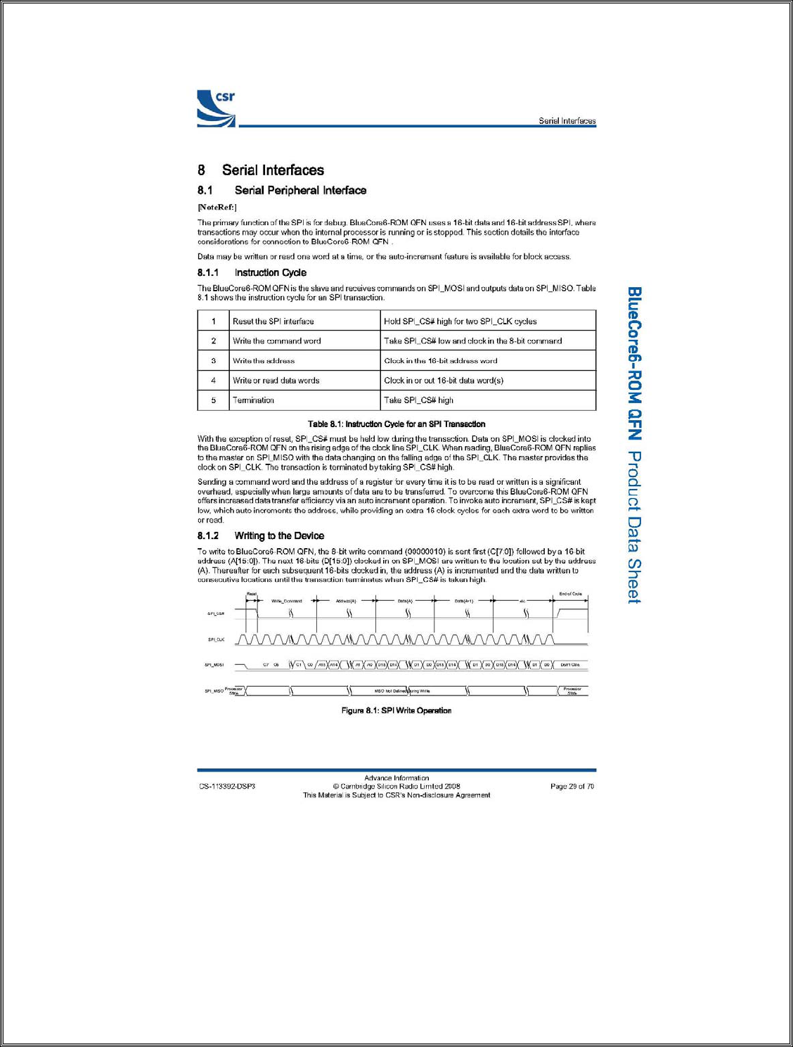
Datalogic Scanning, Inc
959 Terry Street
Eugene, Oregon 97402
Page 123 10/23/2009
Revision X2
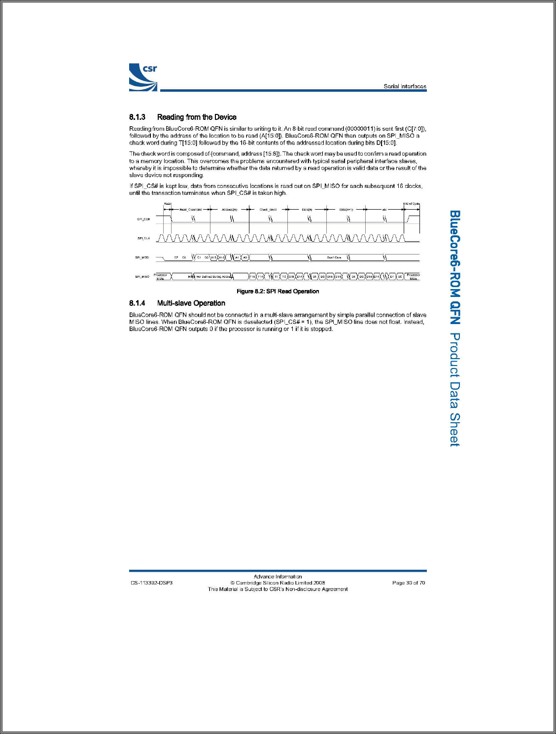
Datalogic Scanning, Inc
959 Terry Street
Eugene, Oregon 97402
Page 124 10/23/2009
Revision X2

Datalogic Scanning, Inc
959 Terry Street
Eugene, Oregon 97402
Page 125 10/23/2009
Revision X2
5. Auto-Baud Detection and Minimum Required PS Keys Settings
The radio, on power up or cold reset, does not know some of the crucial PS Keys for
the radio to operate. The two main PS Keys are the crystal frequency and UART
baud rate. The BC6 has the ability to “auto-baud” detect the UART connection and
allow communications from the host processor. In order to do this the host processor
needs to:
1) Send some data packets at the baud rate to be set. For Datalogic this data rate is
set at 115.2K.
2) These packets should resemble H4 communications packets but not contain valid
messages.
3) Since the BC6 will not recognize the message, as it finally determines the baud
rate, it will send an HCI Hardware Error code of 0Xfe.
4) When the host receives this error it will stop sending non-H4 traffic and send a
HCI Reset Command.
5) The BC6 will recognize this command and then normal HCI traffic/commands
can resume.
6) Since this method can fail, a hardware reset to the BC6 is required (active low) to
allow this process to restart should the BC6 get locked up.
7) The inter-packet timing should be no less then 50ms and no greater the 250ms. It
is advised to use 100ms for the inter-packet timing.
Minimum PS Key Settings
After the HCI communications has been established the internal PS Keys must be set.
To do this normal BCCMD packets are used. The following keys, at a minimum,
need to be set:
Key Address Value Notes
&0001 00dd eeff 00cc aabb Bluetooth address
&01be 01d8 UART baud rate = 115200
&01fe 6590 Crystal frequency set at 26MHz
A warm reset needs to be sent after these keys have been loaded in to the BC6. After
every hard reset or power up this process needs to be done.
Please refer the CSR’s internal applications notes for current notes regarding this process.
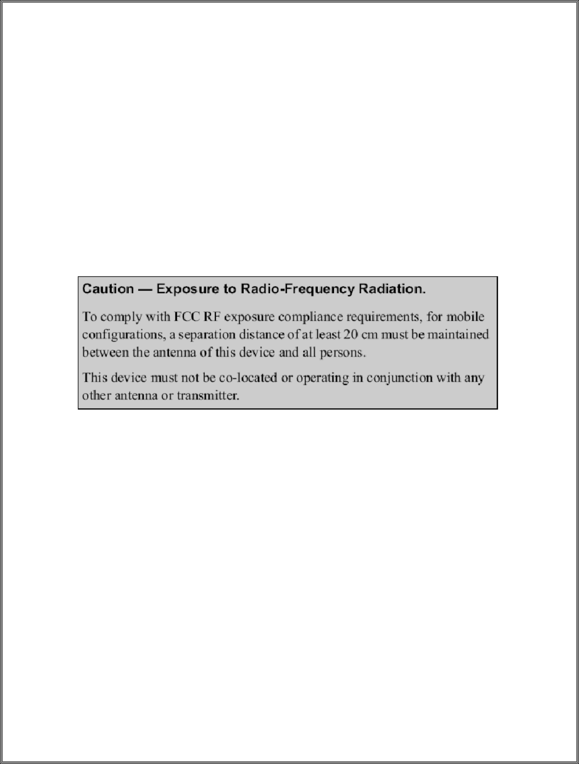
Datalogic Scanning, Inc
959 Terry Street
Eugene, Oregon 97402
Page 126 10/23/2009
Revision X2
FCC Statements
This device complies with part 15 of the FCC Rules. Operation is subject to the
following two conditions: (1) This device may not cause harmful interference, and
(2) this device must accept any interference received, including interference that
may cause undesired operation.
Any changes or modifications not expressly approved by the party responsible for
compliance could void the user’s authority to operate the equipment.