Datalogic ADC PB Bluetooth Module User Manual BC01b AN 047b 17JUL01
Datalogic ADC, Inc. Bluetooth Module BC01b AN 047b 17JUL01
UserManual.wiki
>
Datalogic ADC
>
PB User Manual
Manual
Navigation menu
Upload a User Manual
Namespaces
Wiki Guide
HTML
PDF
Info
Views
User Manual
Discussion / Help
Navigation
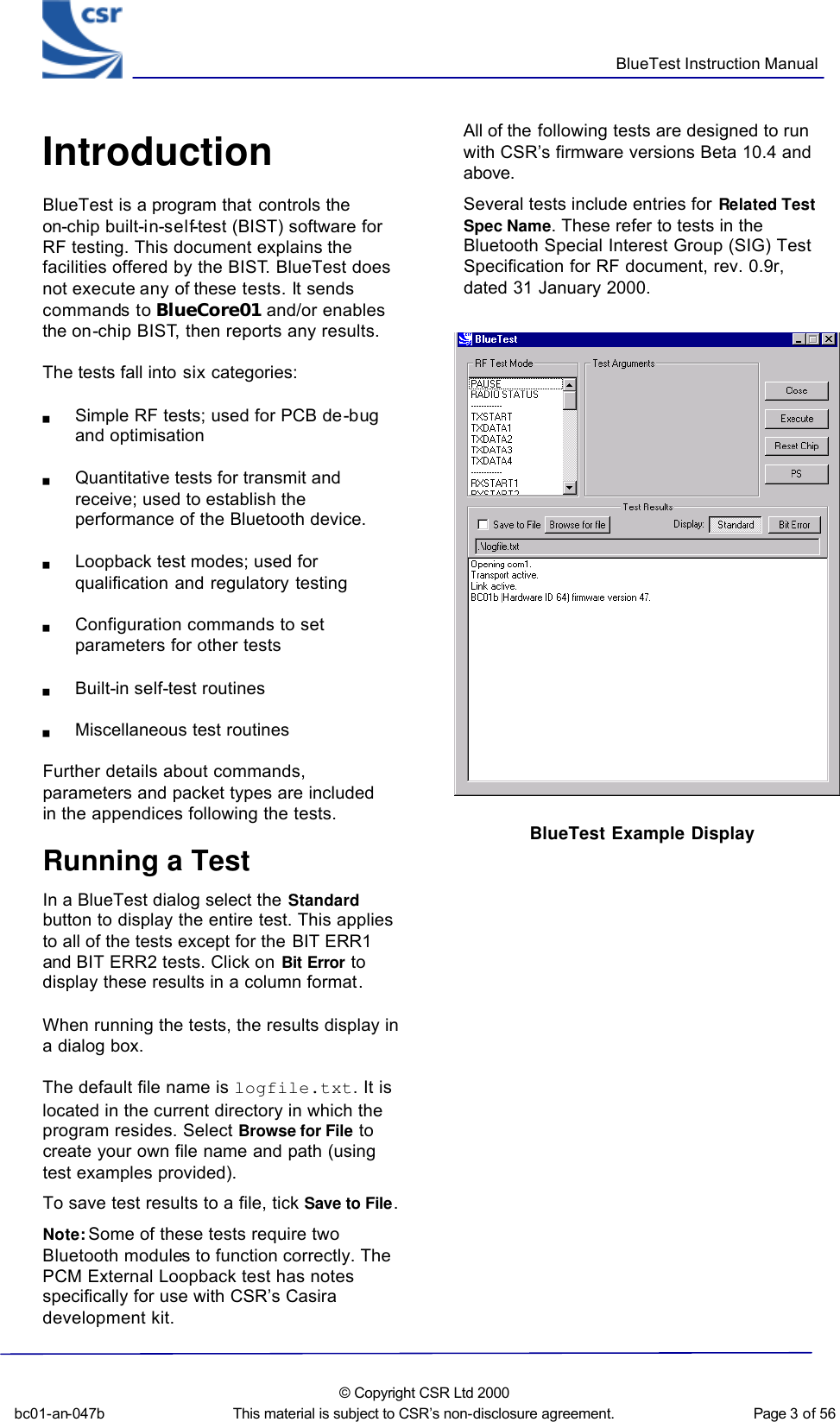
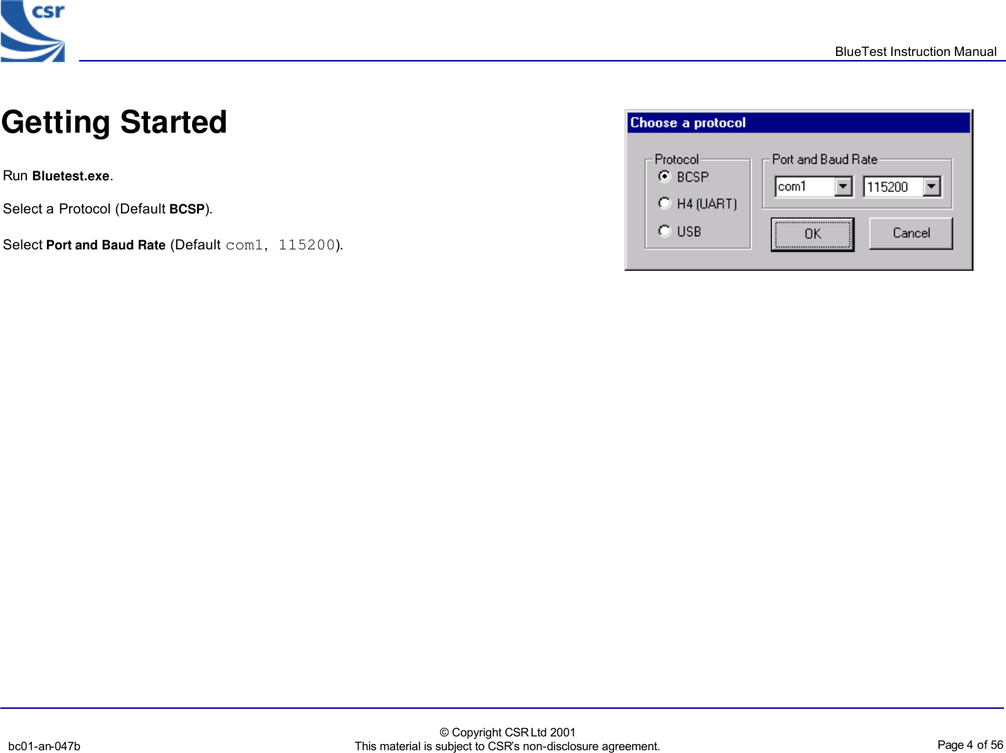
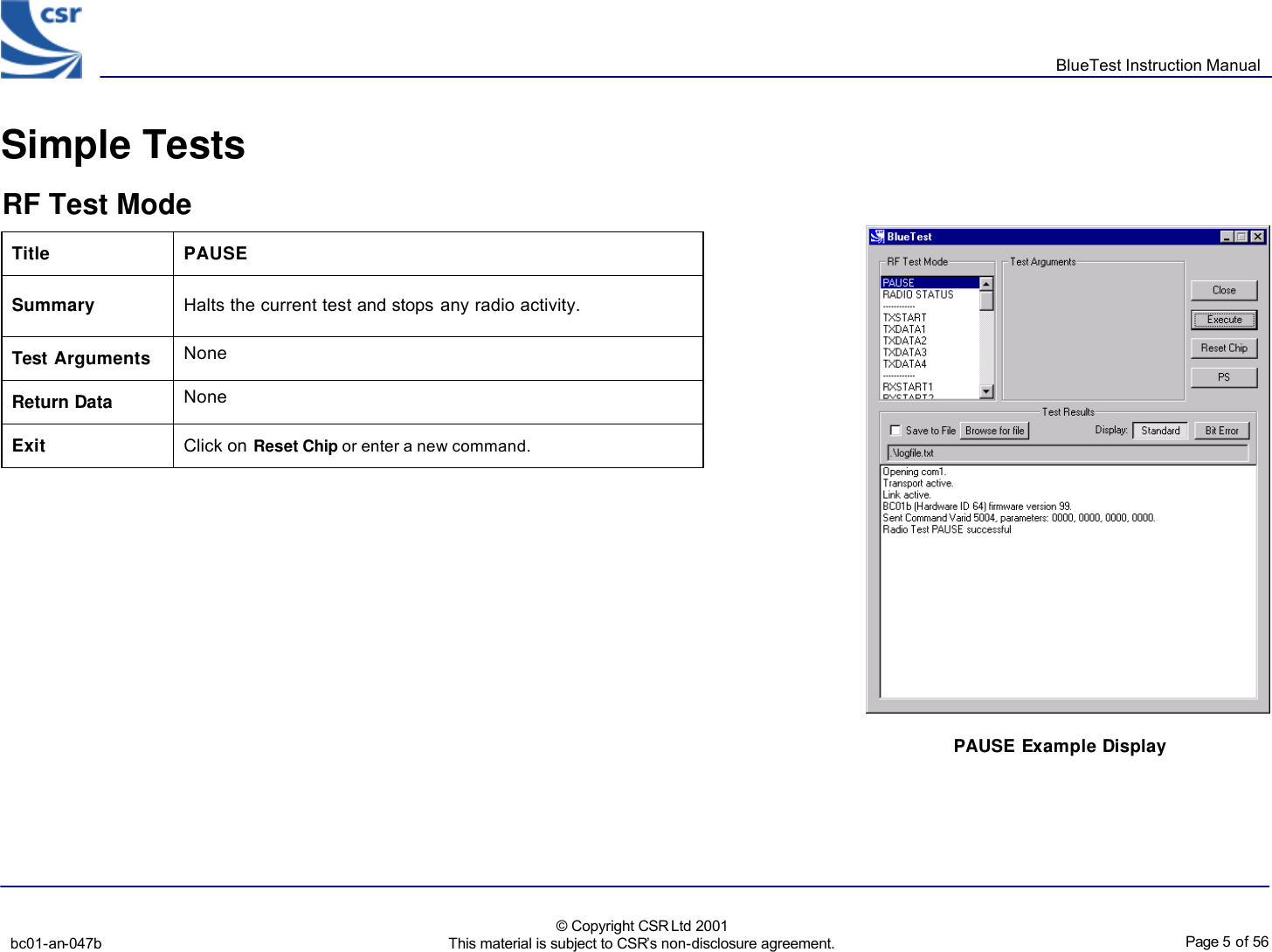
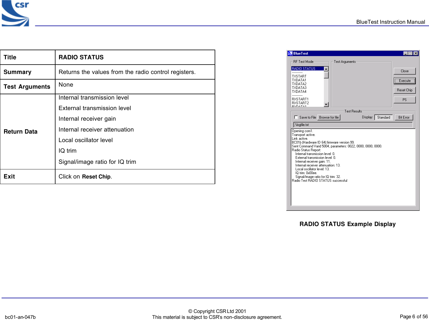
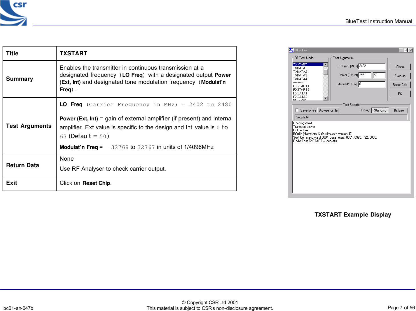
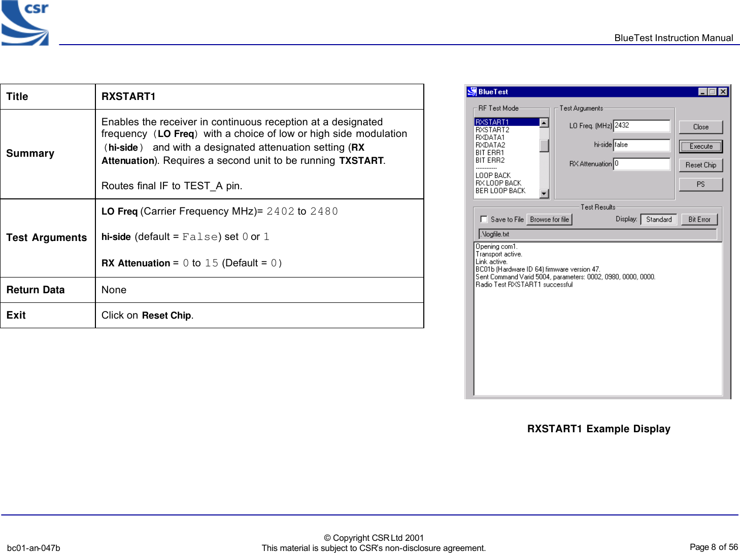
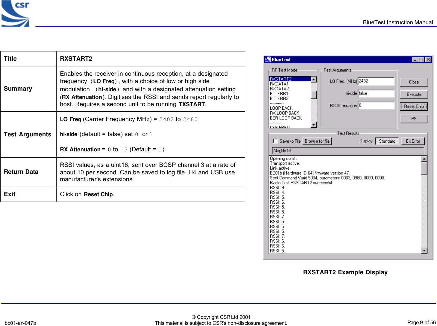
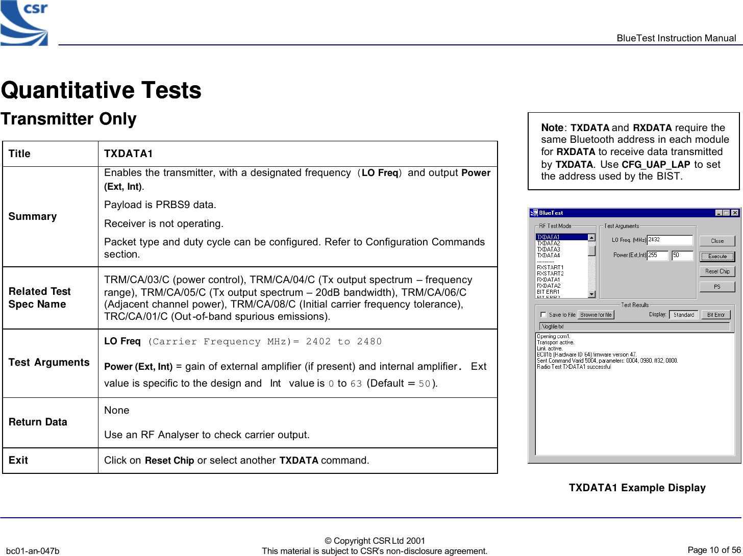
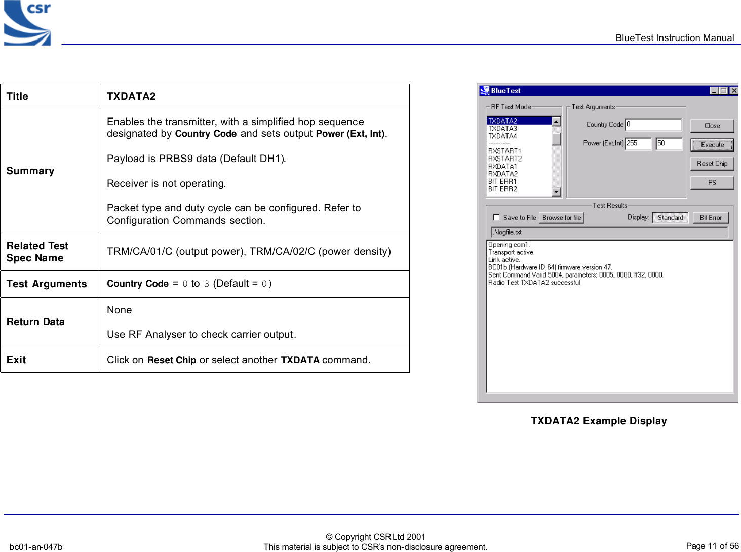
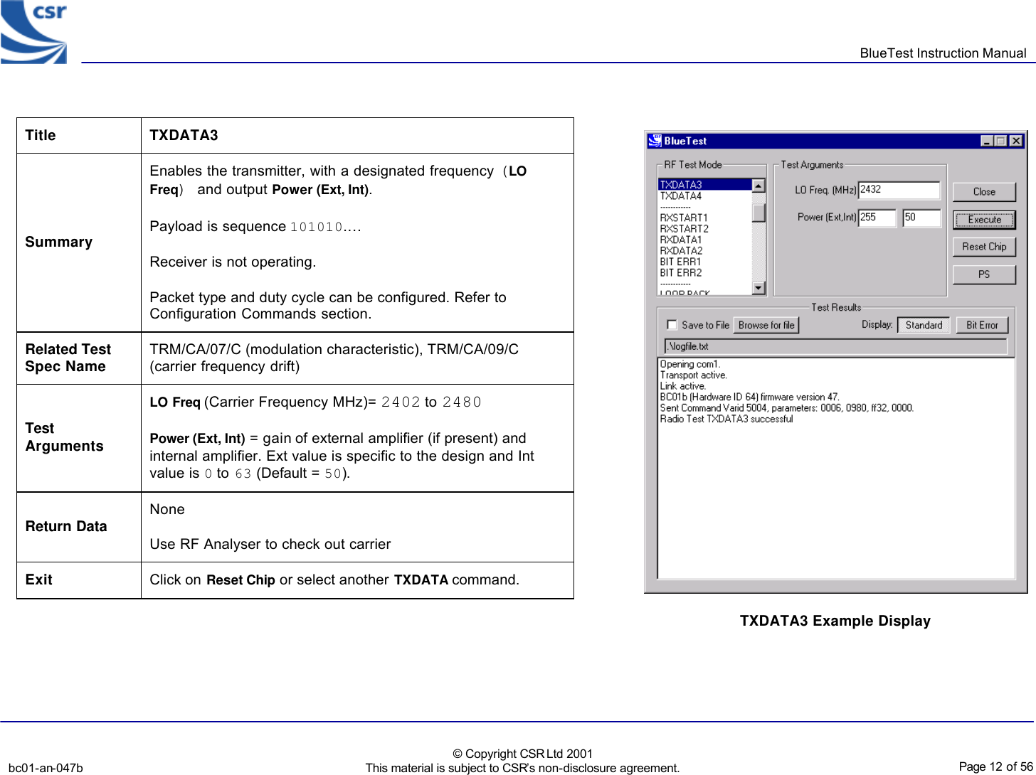
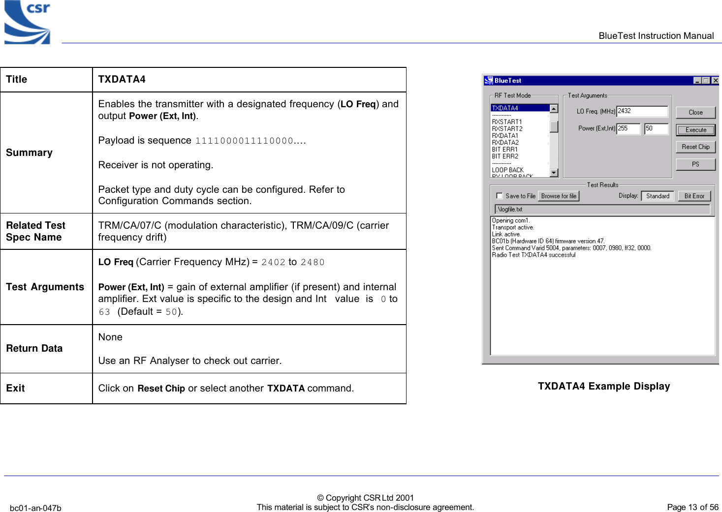
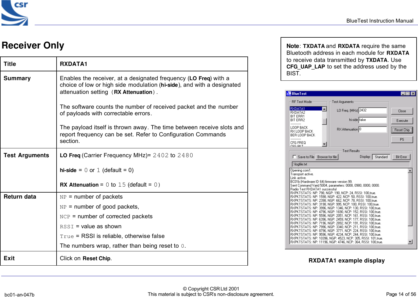
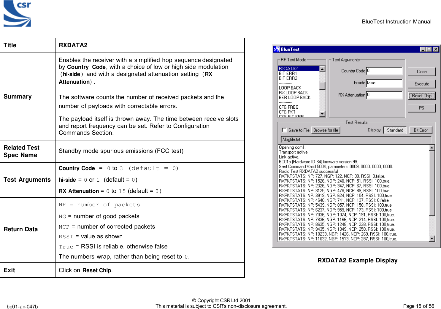
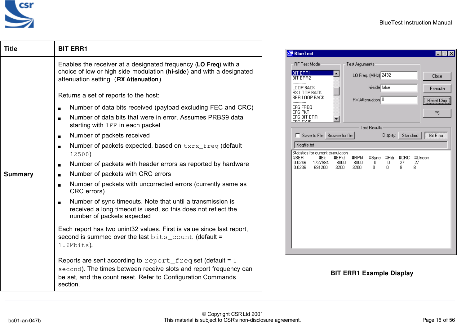
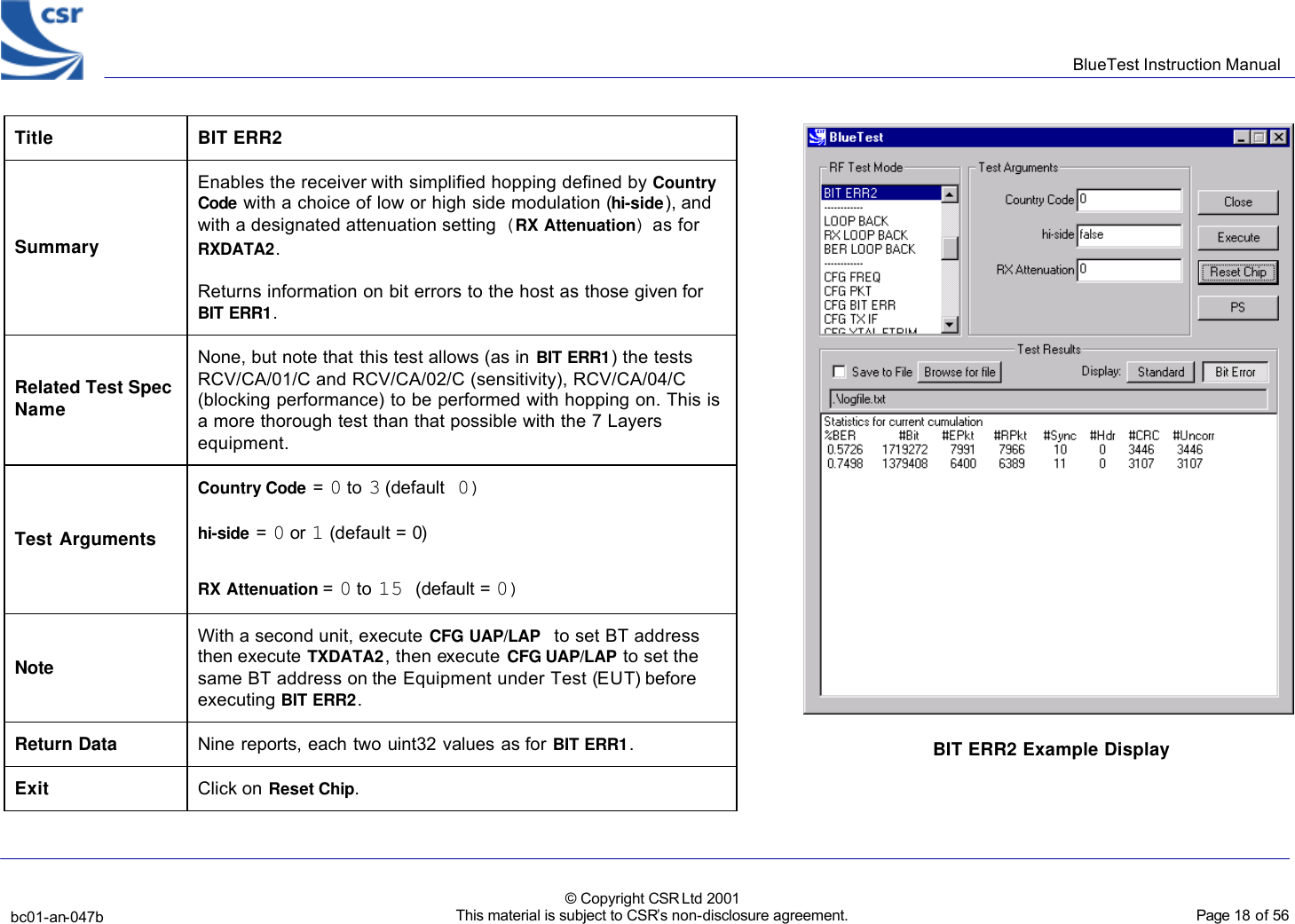
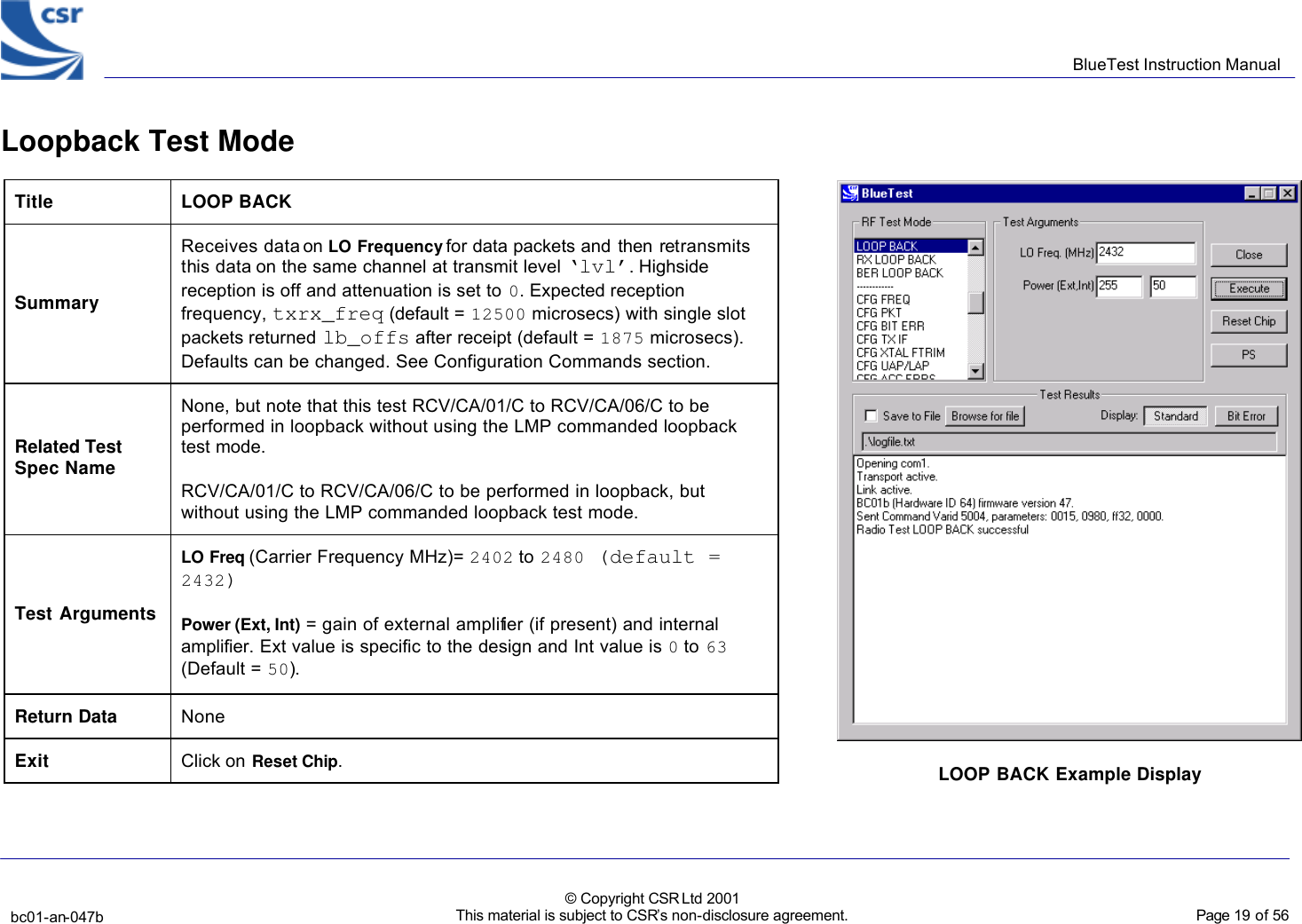
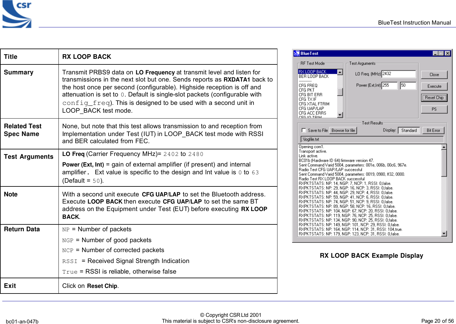
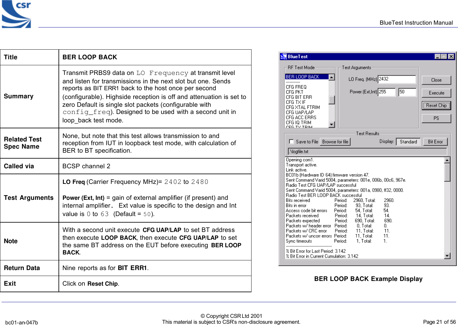
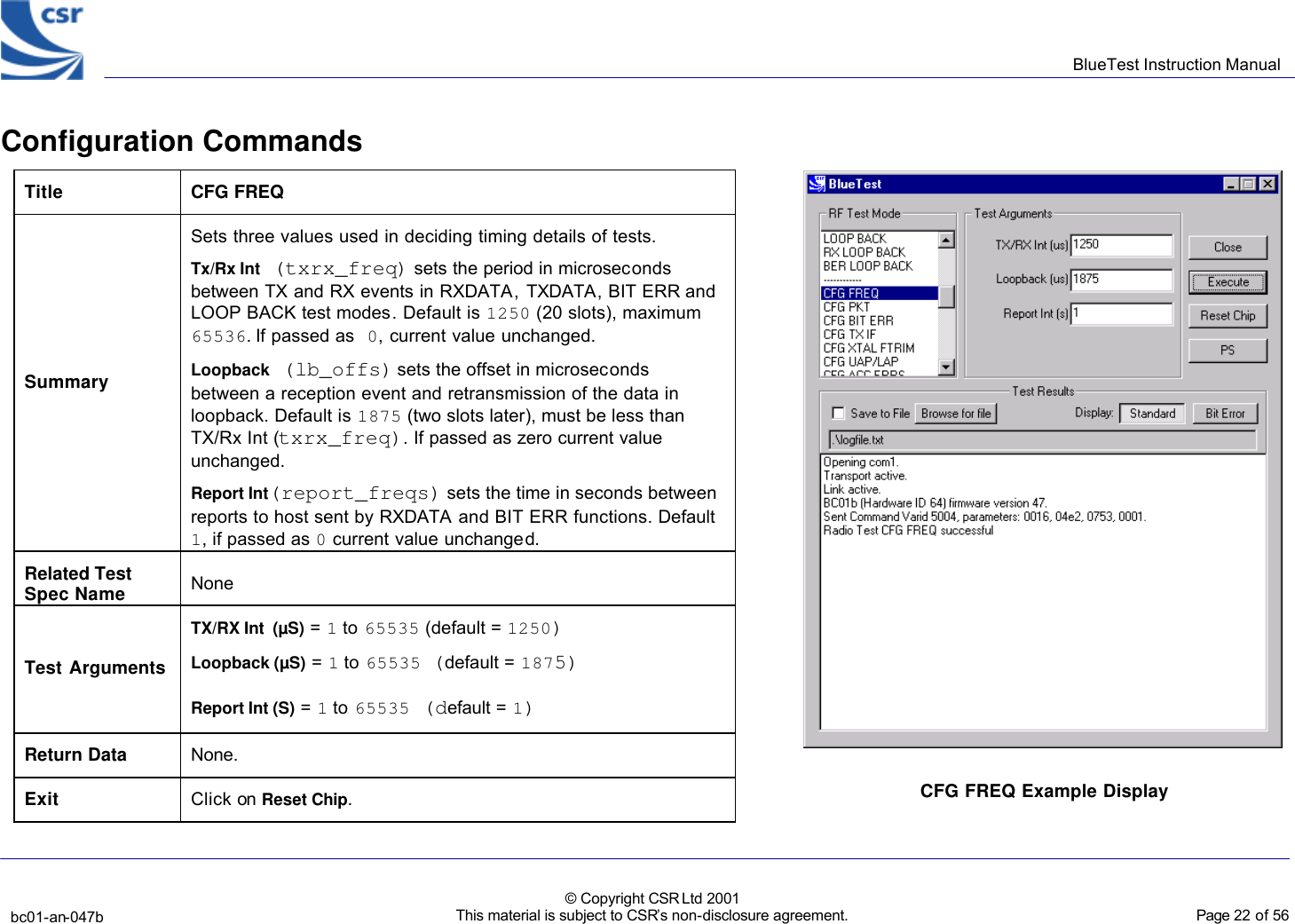
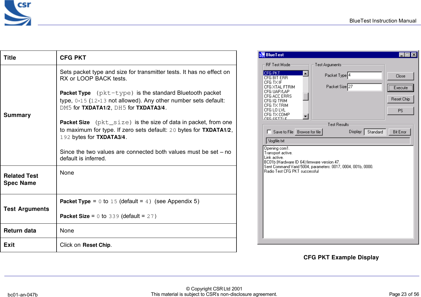
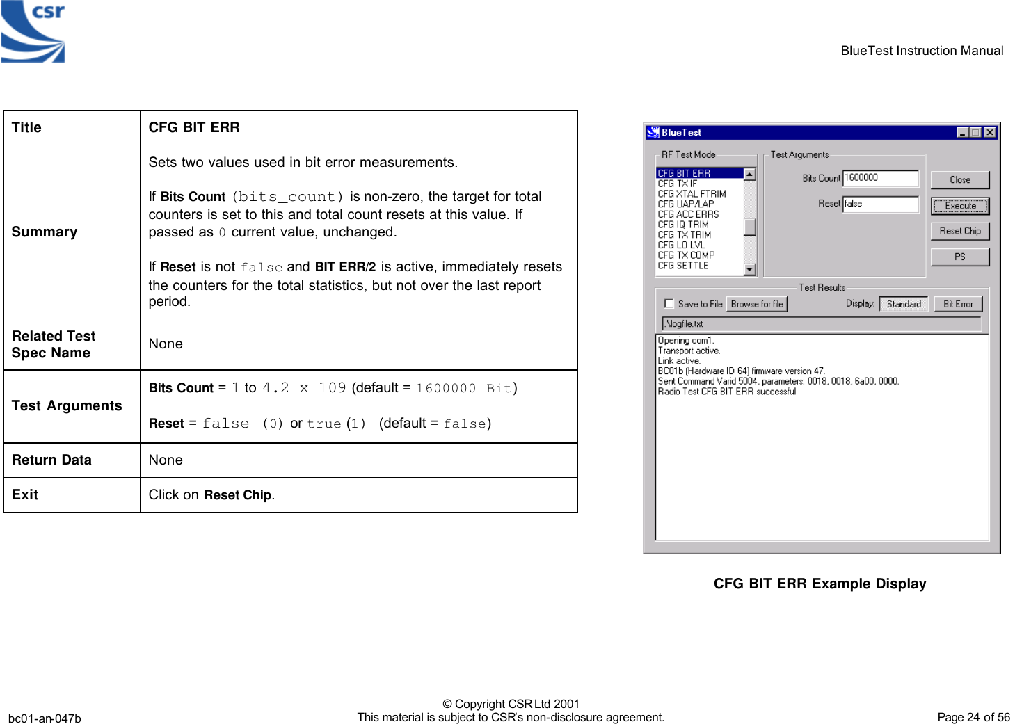
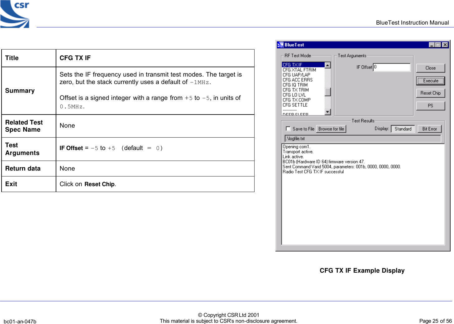
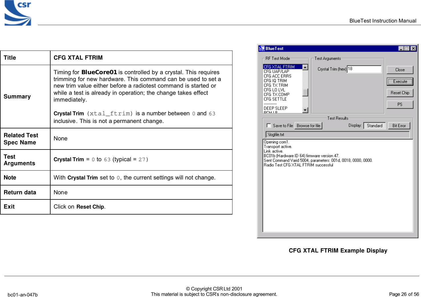
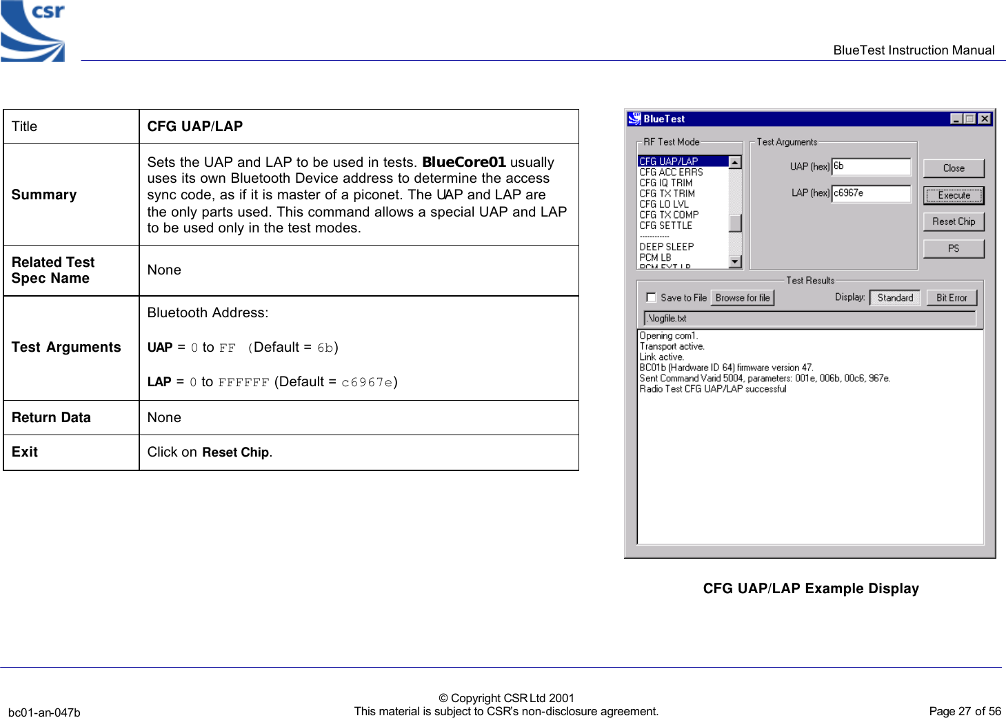
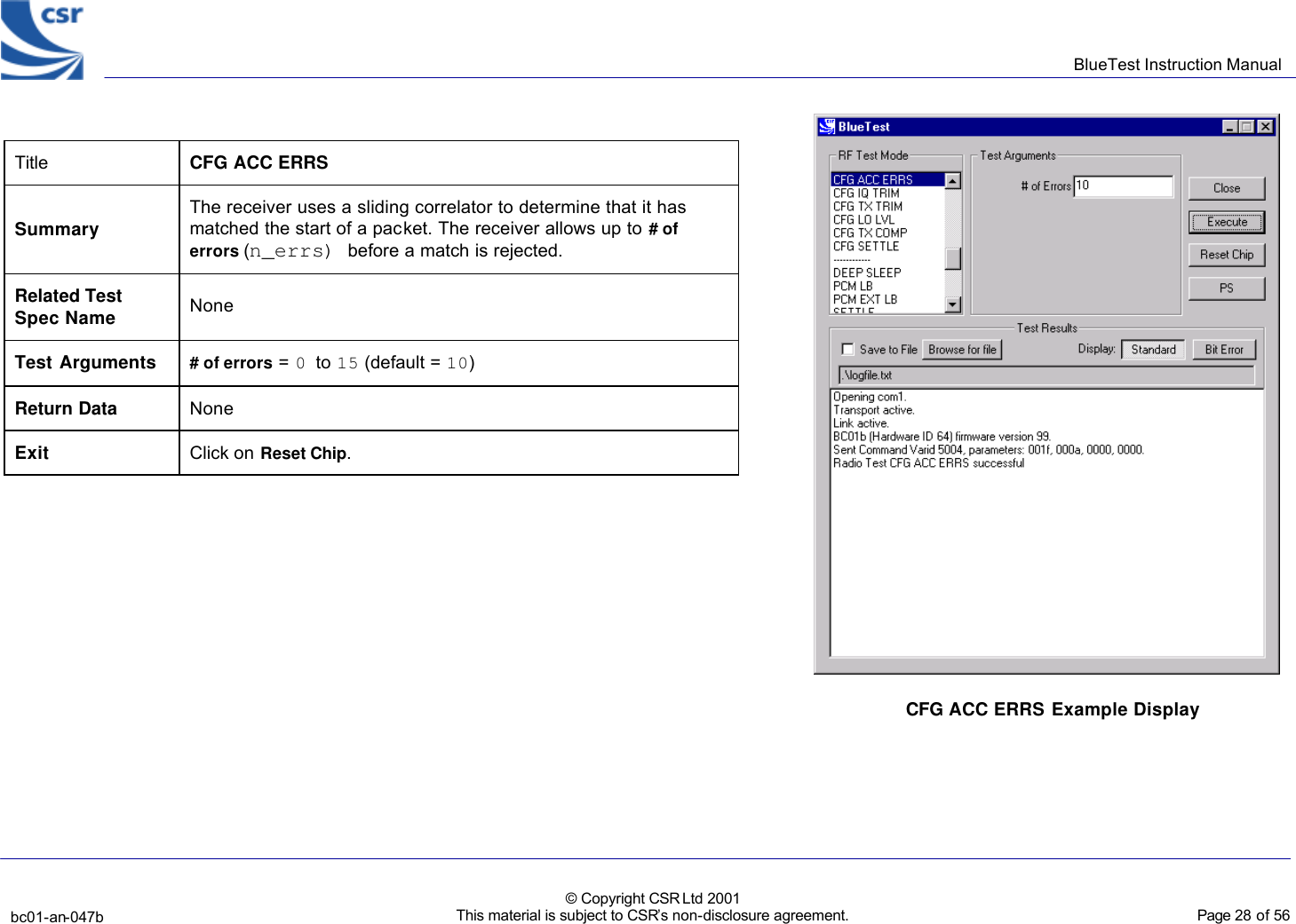
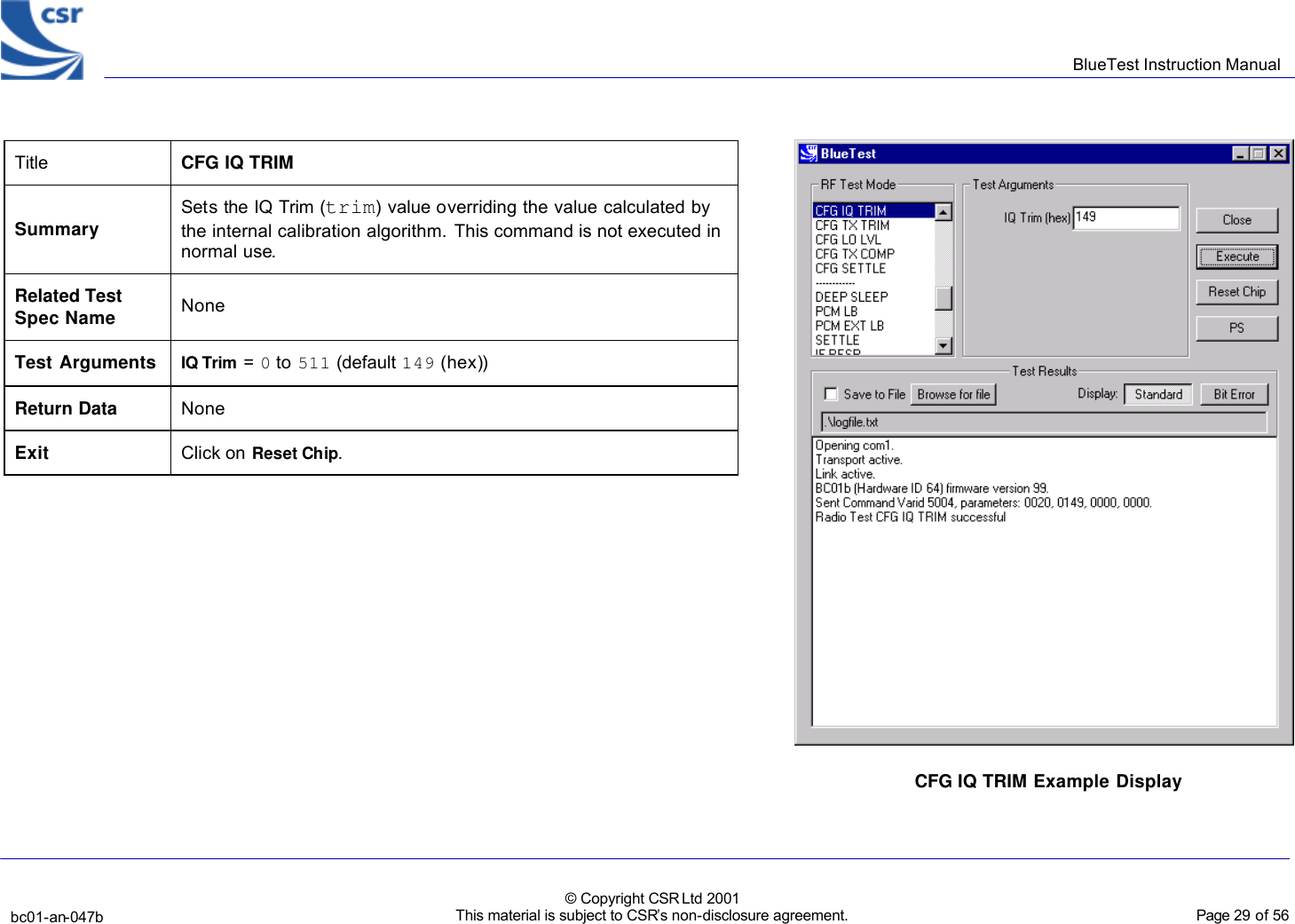
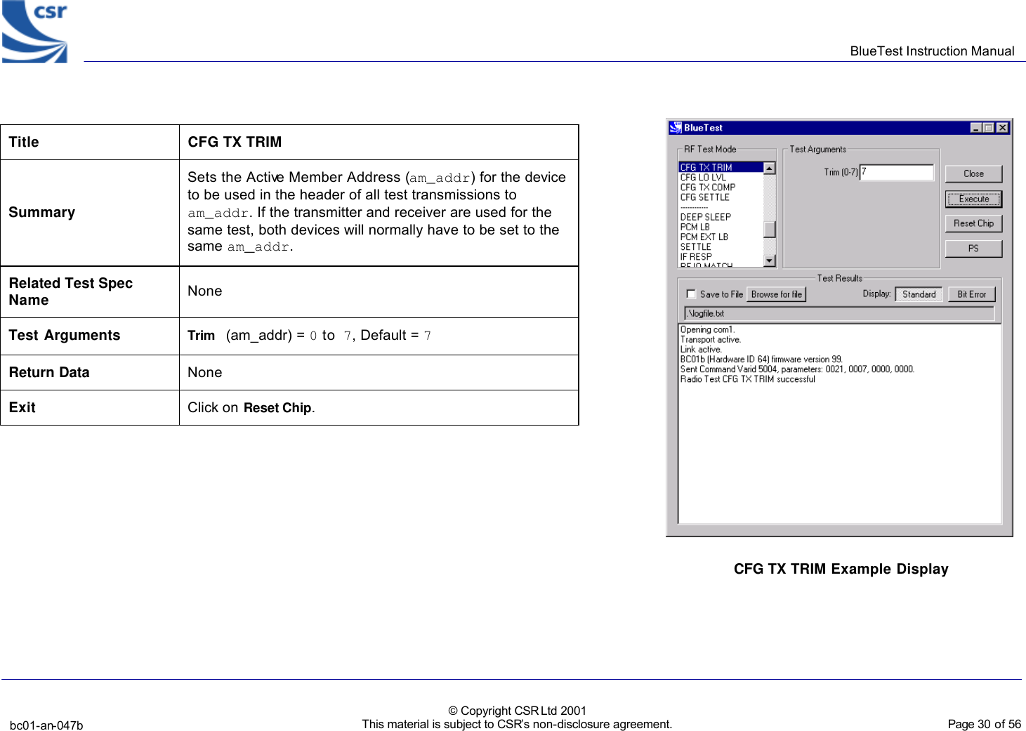
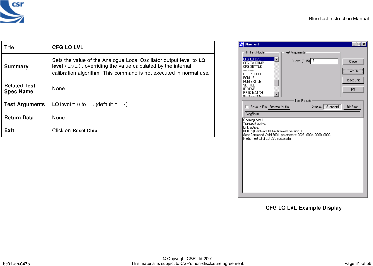
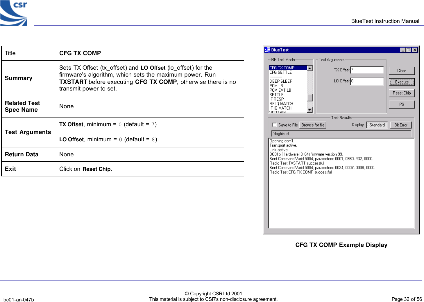

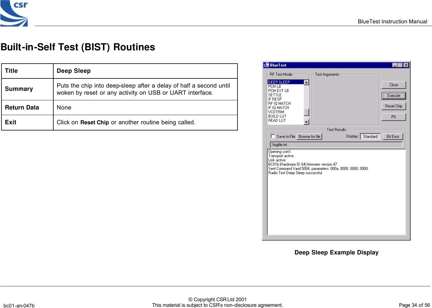
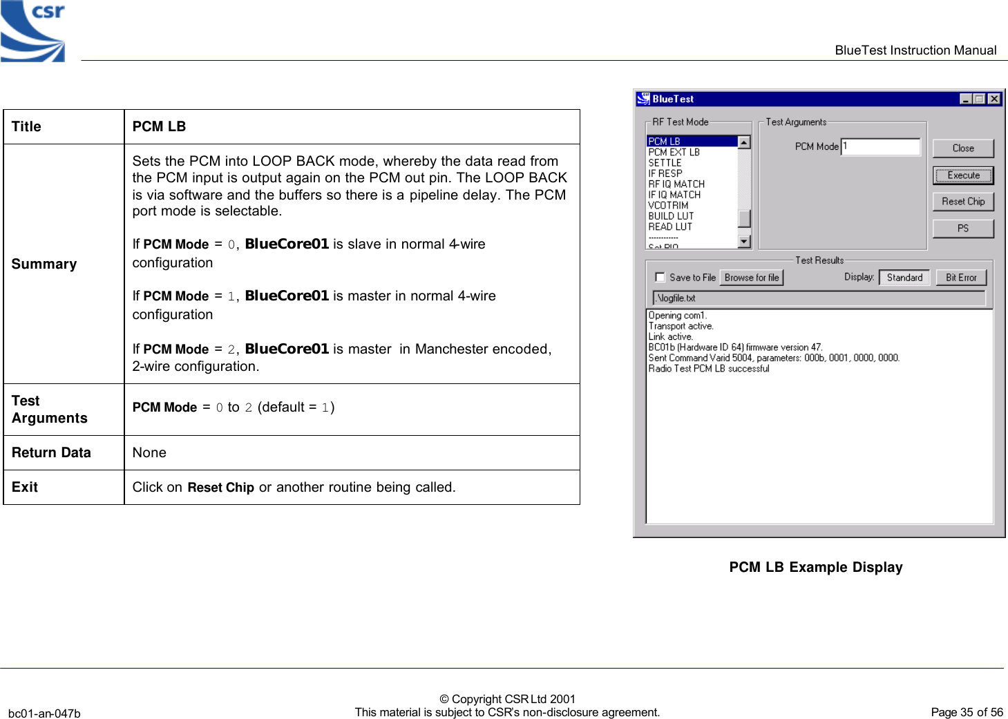
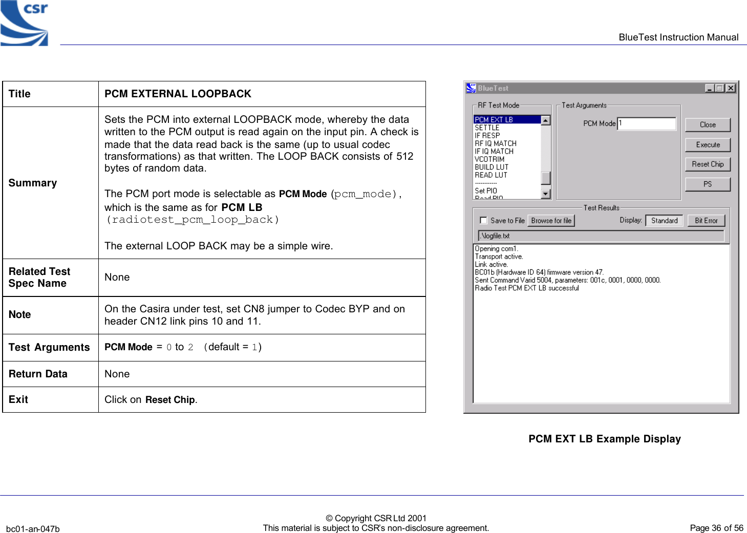
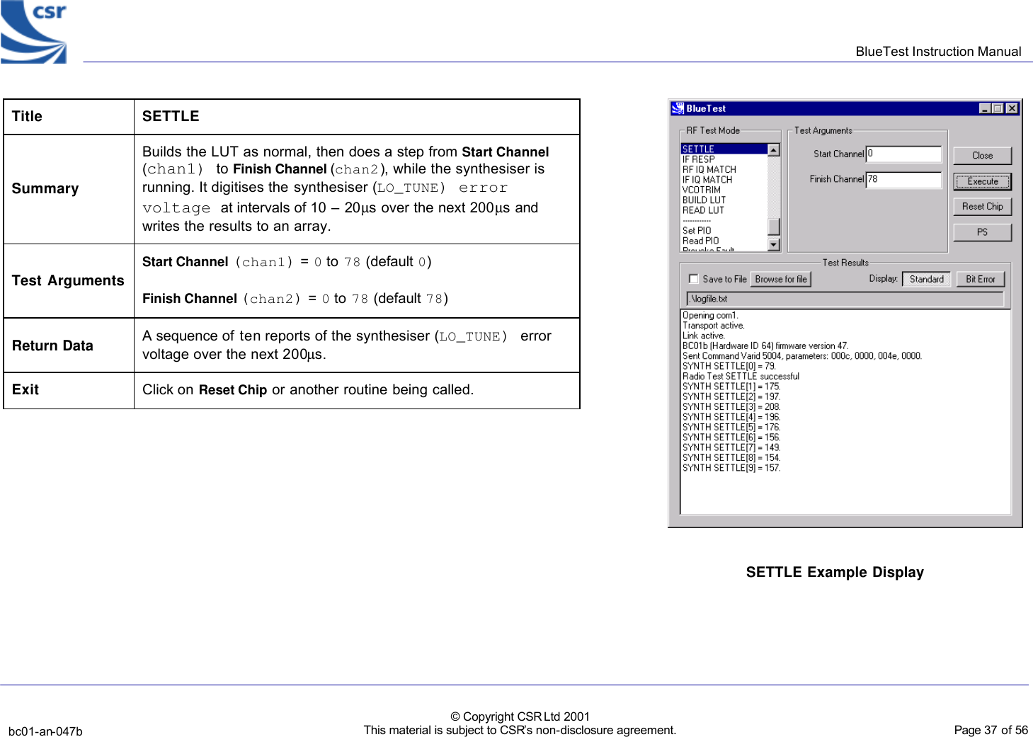
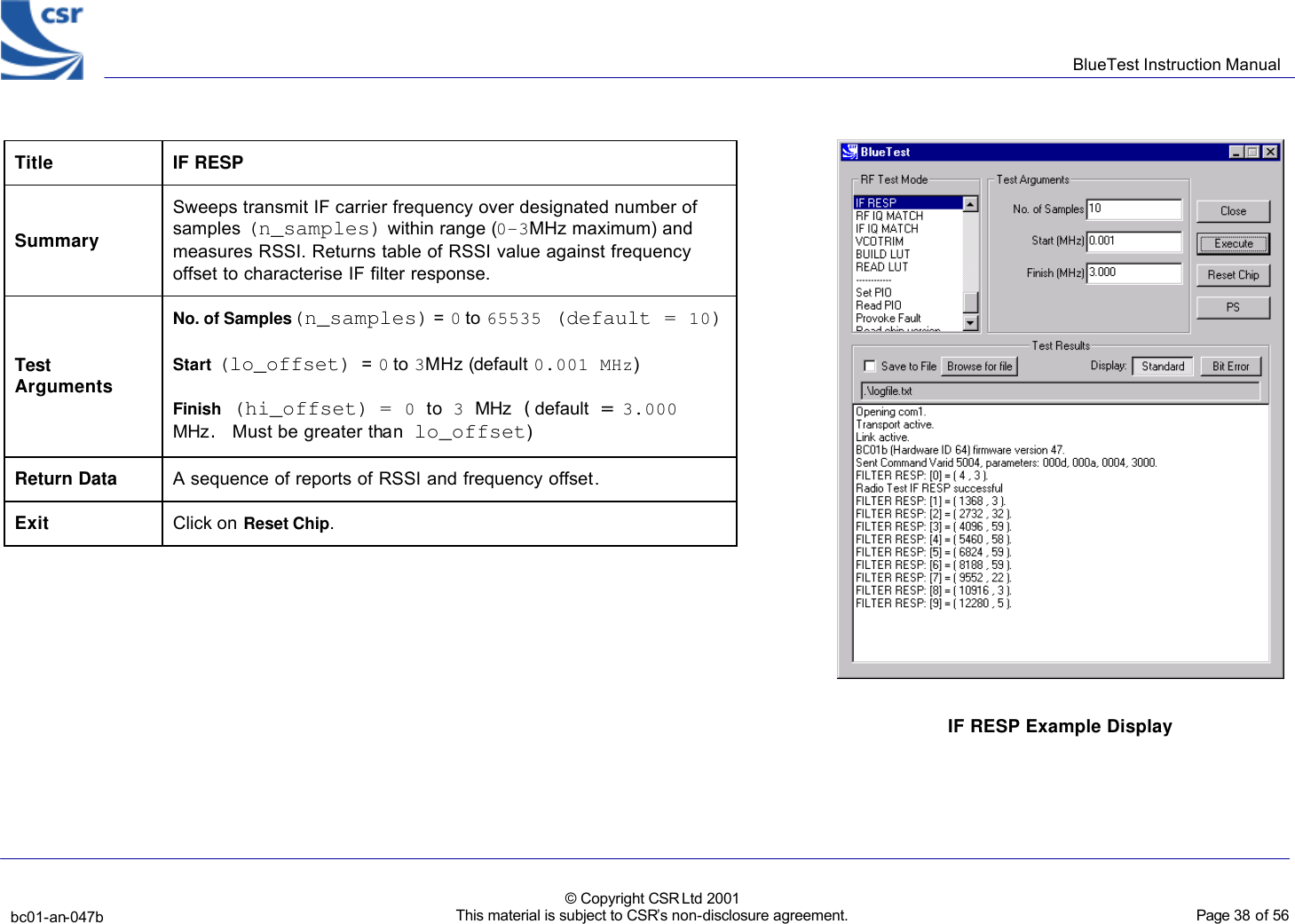
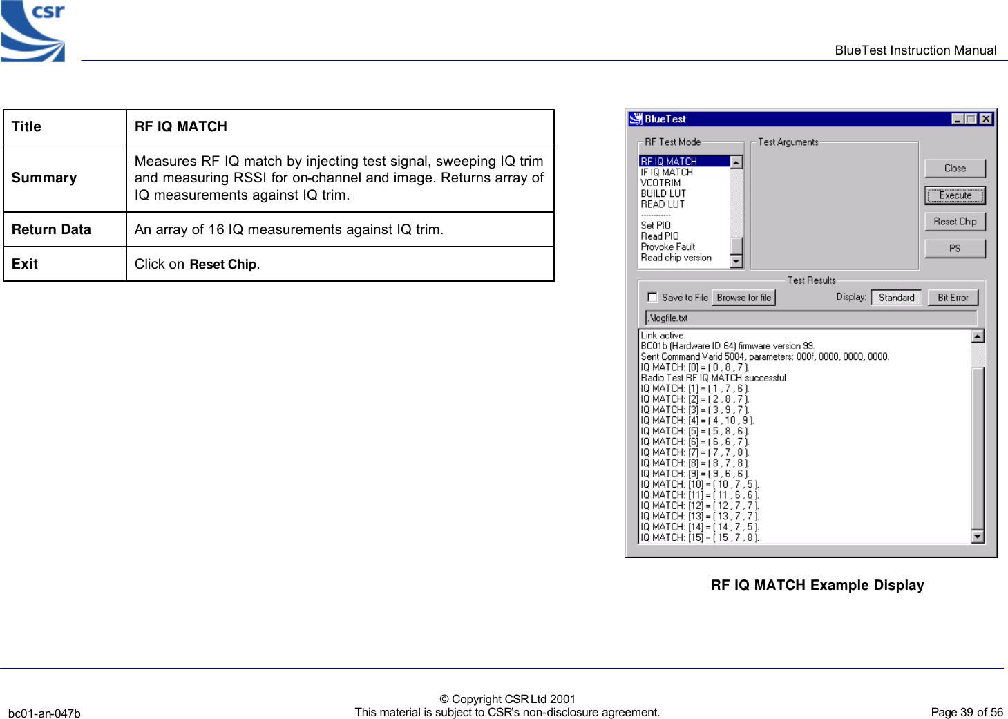
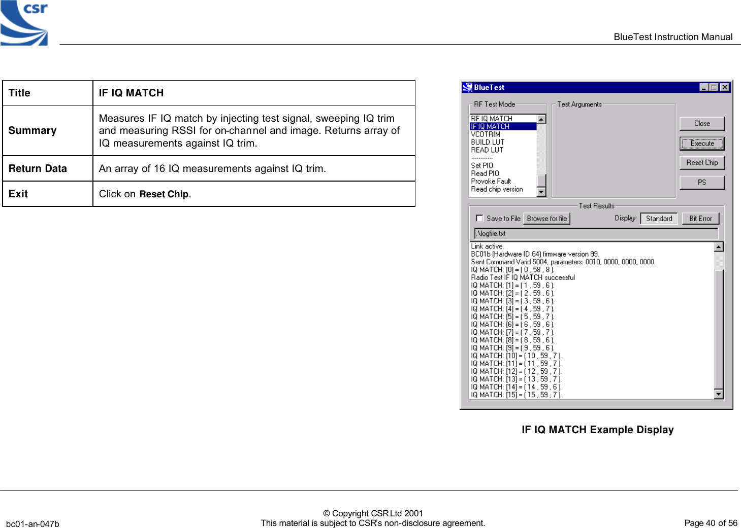
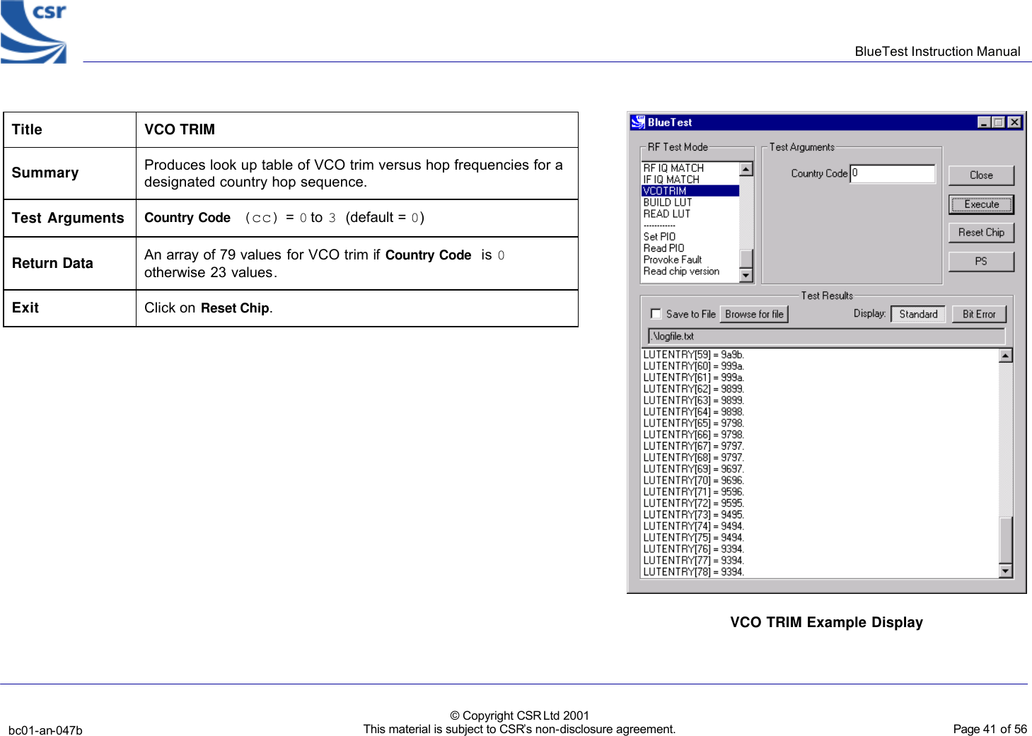
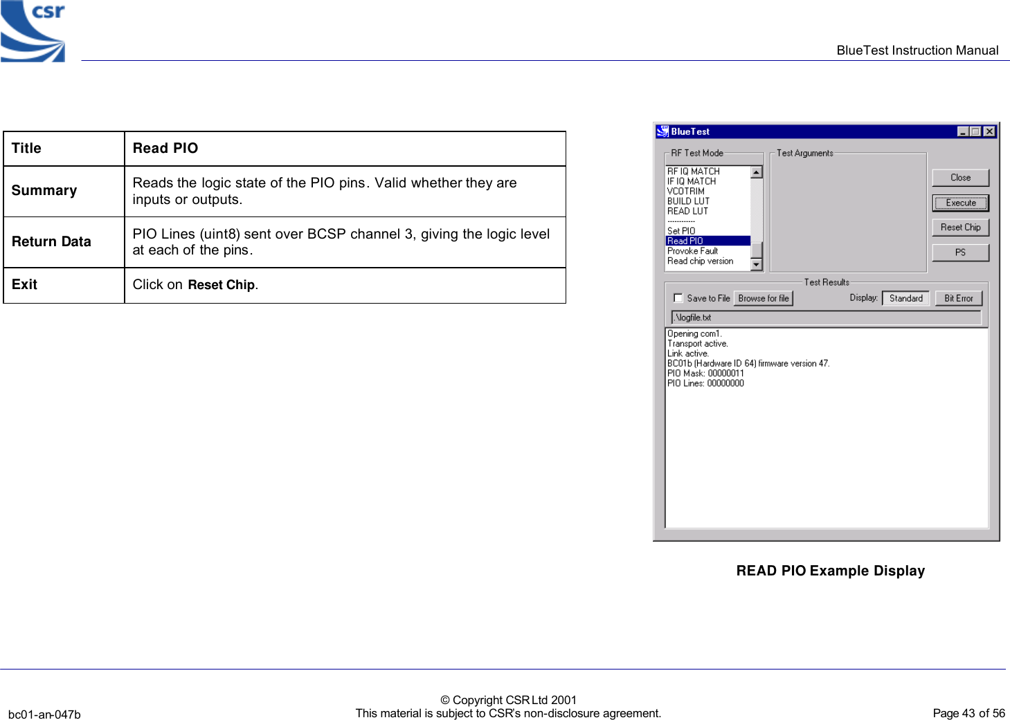
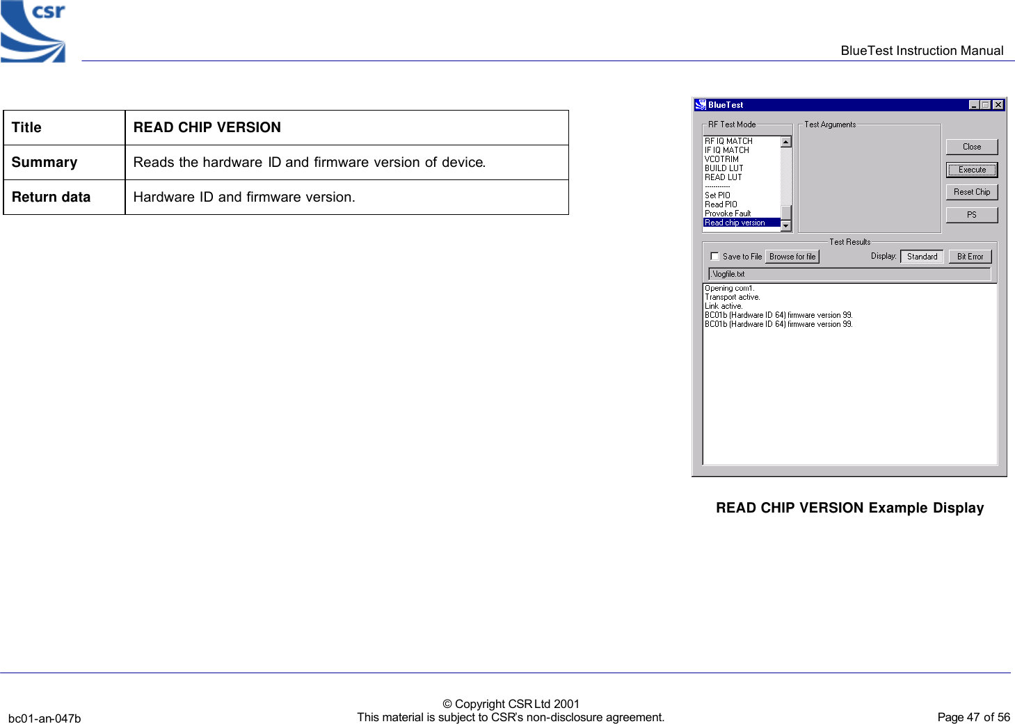
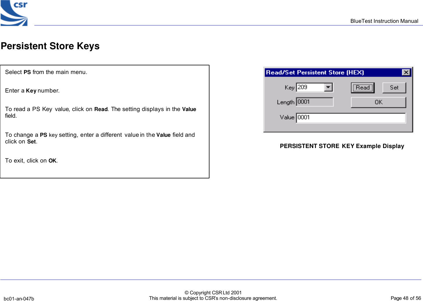
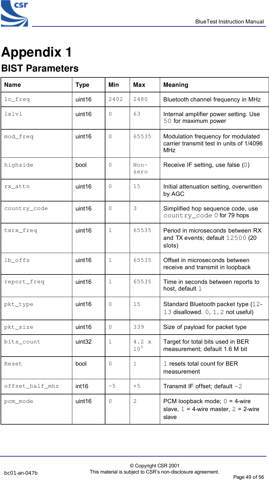
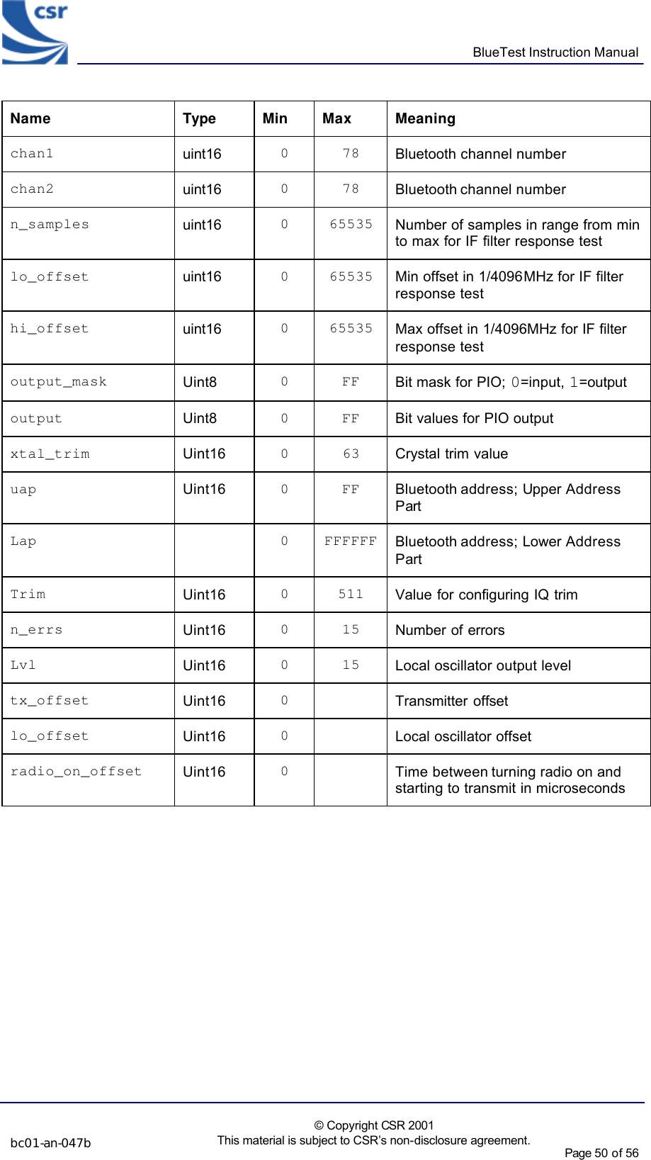
![BlueTest Instruction Manual bc01-an-047b © Copyright CSR Ltd 2001 This material is subject to CSR’s non-disclosure agreement. Page 42 of 56 BlueCoreTM01 Miscellaneous Test Routines Title Set PIO Summary Enables designated PIO lines as outputs and sets them as desired. To be used with caution since it over-rides previous settings. Bit 0 corresponds to PIO[0], and a logic one enables it as an output. Test Arguments Mask (default = 11111111) Values (default = 00000000) Return Data None Exit Click on Reset Chip. Set PIO Example Display](https://usermanual.wiki/Datalogic-ADC/PB/User-Guide-795349-Page-42.png)