Datalogic ADC PB Bluetooth Module User Manual BC01b AN 047b 17JUL01
Datalogic ADC, Inc. Bluetooth Module BC01b AN 047b 17JUL01
Manual
bc01-an-047b
© Copyright CSR 2000
This material is subject to CSR’s non-disclosure agreement.
CSR
Unit 400 Cambridge Science Park
Milton Road
Cambridge CB4 0WH
UK
Registered in UK 3665875
Tel: +44 (0)1223 692000
Fax: +44 (0)1223 692001
http://www.csr.com
BlueCore01
BlueTest Instruction Manual
AN047
July 2001
Falcon / BTL040

BlueTest Instruction Manual
bc01-an-047b
© Copyright CSR Ltd 2000
This material is subject to CSR’s non-disclosure agreement
Page 2 of 56
BlueCore
TM
01
Contents
Contents...............................................................................................................................2
Introduction ..........................................................................................................................3
Getting Started Simple Tests ...............................................................................................4
Simple Tests ........................................................................................................................5
Quantitative Tests............................................................................................................... 10
Transmitter Only............................................................................................................... 10
Receiver Only................................................................................................................... 14
Loopback Test Mode ........................................................................................................ 16
Configuration Commands.................................................................................................. 22
Built-in-Self Test (BIST) Routines....................................................................................... 22
Miscellaneous Test Routines ............................................................................................. 42
Persistent Store Keys......................................................................................................... 49
Appendix 1.......................................................................................................................... 49
BIST Parameters .............................................................................................................. 49
Appendix 2.......................................................................................................................... 51
Known Software Issue(s) in BlueTest Version 1.4........................................................... 51
Appendix 3.......................................................................................................................... 52
Combining Tests Using a Second Unit ............................................................................... 52
Appendix 4.......................................................................................................................... 52
Configuration Commands Available During Tests................................................................ 53
Appendix 5.......................................................................................................................... 54
Bluetooth Packet Types .................................................................................................... 54
BlueTest Instruction Manual
bc01-an-047b
© Copyright CSR Ltd 2000
This material is subject to CSR’s non-disclosure agreement.
Page 3 of 56
BlueCore
TM
01
Introduction
BlueTest is a program that controls the
on-chip built-in-self-test (BIST) software for
RF testing. This document explains the
facilities offered by the BIST. BlueTest does
not execute any of these tests. It sends
commands to BlueCore01 and/or enables
the on-chip BIST, then reports any results.
The tests fall into six categories:
g Simple RF tests; used for PCB de-bug
and optimisation
g Quantitative tests for transmit and
receive; used to establish the
performance of the Bluetooth device.
g Loopback test modes; used for
qualification and regulatory testing
g Configuration commands to set
parameters for other tests
g Built-in self-test routines
g Miscellaneous test routines
Further details about commands,
parameters and packet types are included
in the appendices following the tests.
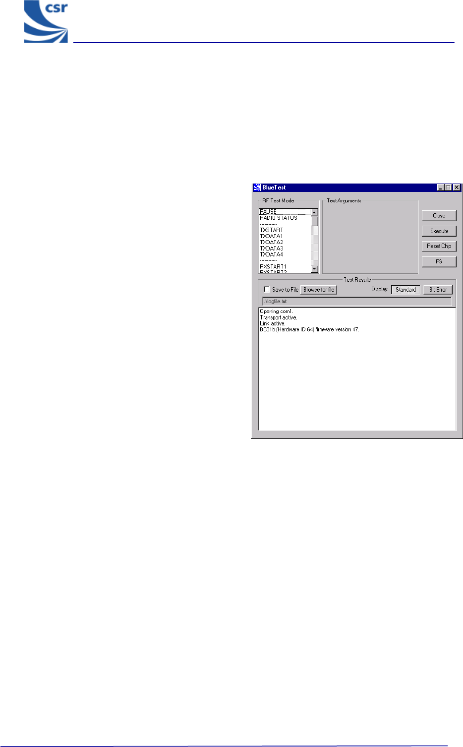
Running a Test
In a BlueTest dialog select the Standard
button to display the entire test. This applies
to all of the tests except for the BIT ERR1
and BIT ERR2 tests. Click on Bit Error to
display these results in a column format.
When running the tests, the results display in
a dialog box.
The default file name is logfile.txt. It is
located in the current directory in which the
program resides. Select Browse for File to
create your own file name and path (using
test examples provided).
To save test results to a file, tick Save to File.
Note:
Some of these tests require two
Bluetooth modules to function correctly. The
PCM External Loopback test has notes
specifically for use with CSR’s Casira
development kit.
All of the following tests are designed to run
with CSR’s firmware versions Beta 10.4 and
above.
Several tests include entries for Related Test
Spec Name. These refer to tests in the
Bluetooth Special Interest Group (SIG) Test
Specification for RF document, rev. 0.9r,
dated 31 January 2000.
BlueTest Example Display
BlueTest Instruction Manual
bc01-an-047b
© Copyright CSR Ltd 2001
This material is subject to CSR’s non-disclosure agreement.
Page 4 of 56
BlueCoreTM01
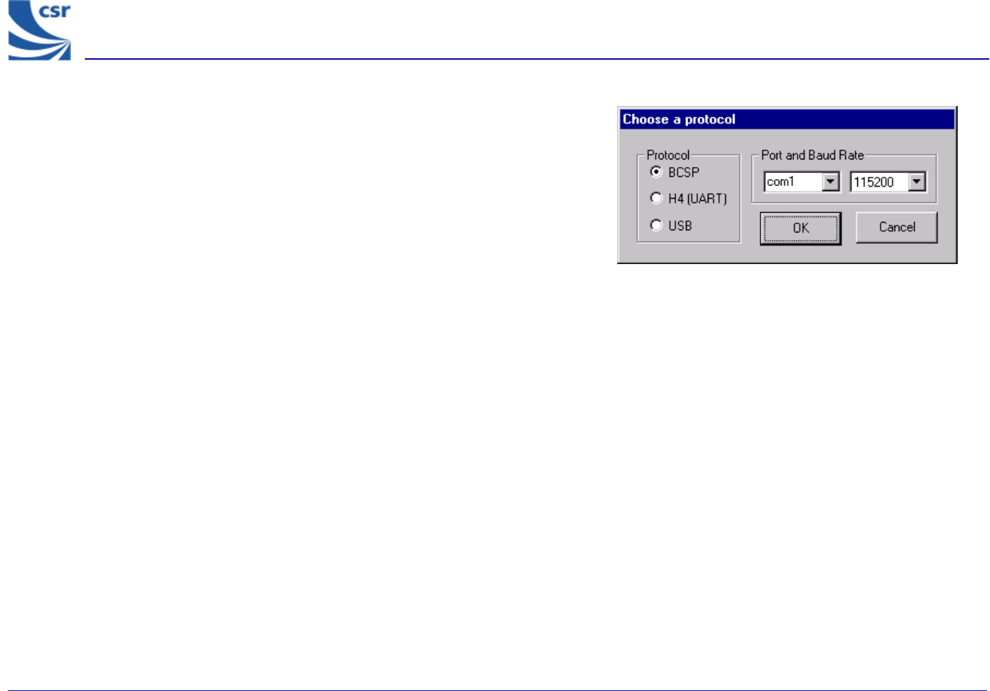
Getting Started
Run Bluetest.exe.
Select a Protocol (Default BCSP).
Select Port and Baud Rate (Default com1, 115200).
BlueTest Instruction Manual
bc01-an-047b
© Copyright CSR Ltd 2001
This material is subject to CSR’s non-disclosure agreement.
Page 5 of 56
BlueCoreTM01
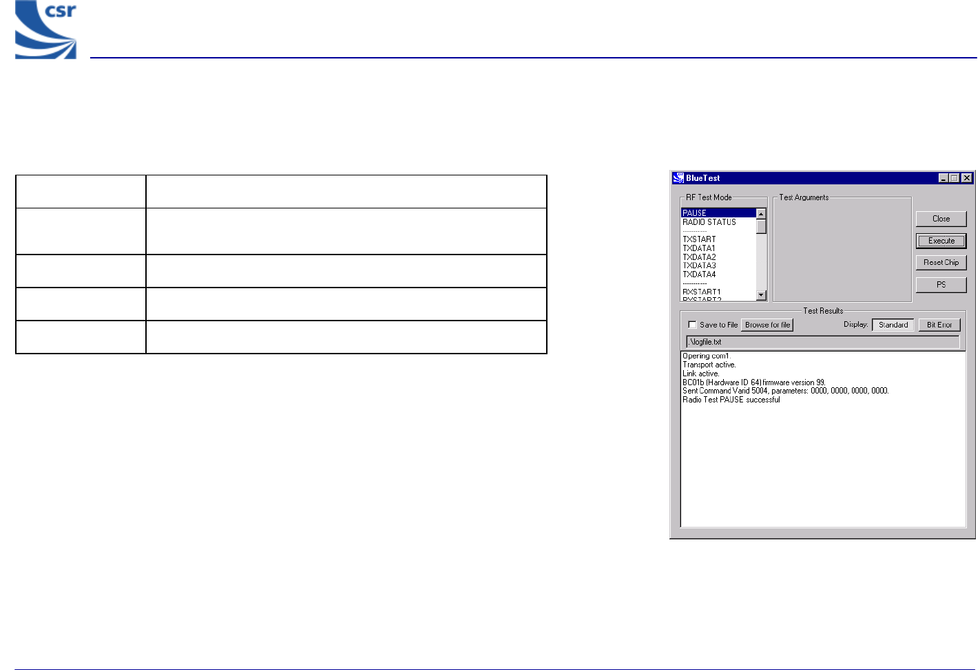
Simple Tests
RF Test Mode
Title PAUSE
Summary Halts the current test and stops any radio activity.
Test Arguments None
Return Data None
Exit Click on Reset Chip or enter a new command.
PAUSE Example Display
BlueTest Instruction Manual
bc01-an-047b
© Copyright CSR Ltd 2001
This material is subject to CSR’s non-disclosure agreement.
Page 6 of 56
BlueCoreTM01
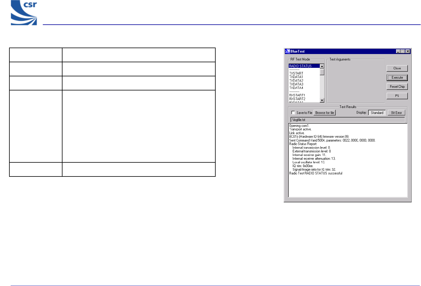
RADIO STATUS Example Display
Title RADIO STATUS
Summary Returns the values from the radio control registers.
Test Arguments None
Return Data
Internal transmission level
External transmission level
Internal receiver gain
Internal receiver attenuation
Local oscillator level
IQ trim
Signal/image ratio for IQ trim
Exit Click on Reset Chip.
BlueTest Instruction Manual
bc01-an-047b
© Copyright CSR Ltd 2001
This material is subject to CSR’s non-disclosure agreement.
Page 7 of 56
BlueCoreTM01
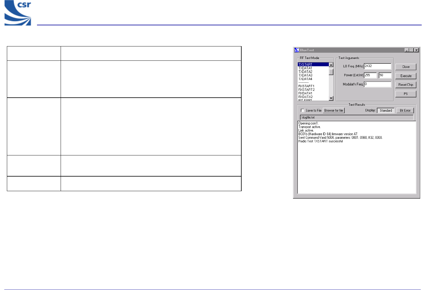
Title TXSTART
Summary
Enables the transmitter in continuous transmission at a
designated frequency (LO Freq) with a designated output Power
(Ext, Int) and designated tone modulation frequency (Modulat’n
Freq).
Test Arguments
LO Freq (Carrier Frequency in MHz) = 2402 to 2480
Power (Ext, Int) = gain of external amplifier (if present) and internal
amplifier. Ext value is specific to the design and Int value is 0 to
63 (Default = 50)
Modulat’n Freq = -32768 to 32767 in units of 1/4096MHz
Return Data None
Use RF Analyser to check carrier output.
Exit Click on Reset Chip.
TXSTART Example Display
BlueTest Instruction Manual
bc01-an-047b
© Copyright CSR Ltd 2001
This material is subject to CSR’s non-disclosure agreement.
Page 8 of 56
BlueCoreTM01
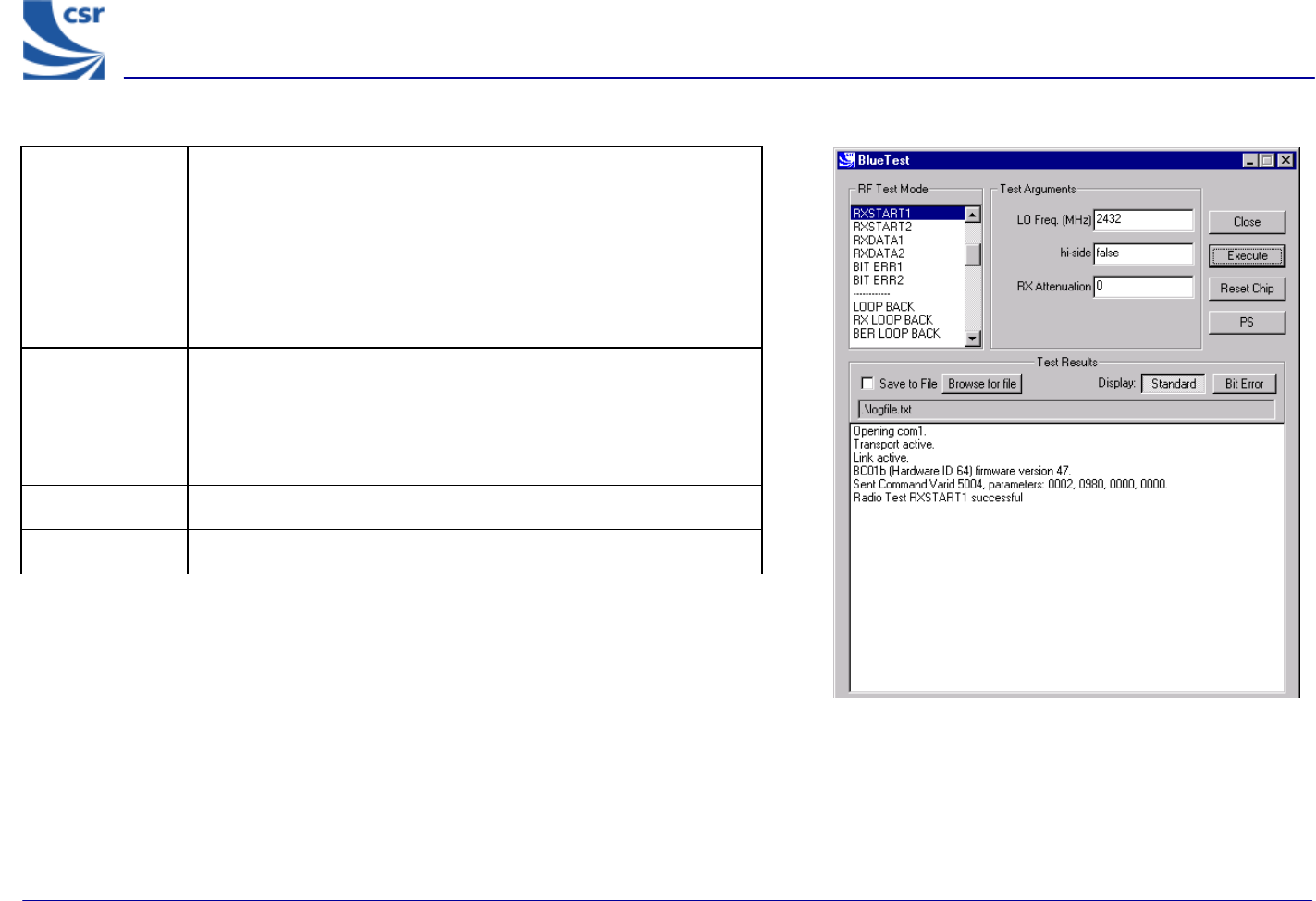
Title RXSTART1
Summary
Enables the receiver in continuous reception at a designated
frequency (LO Freq) with a choice of low or high side modulation
(hi-side) and with a designated attenuation setting (RX
Attenuation). Requires a second unit to be running TXSTART.
Routes final IF to TEST_A pin.
Test Arguments
LO Freq (Carrier Frequency MHz)= 2402 to 2480
hi-side (default = False) set 0 or 1
RX Attenuation = 0 to 15 (Default = 0)
Return Data None
Exit Click on Reset Chip.
RXSTART1 Example Display
BlueTest Instruction Manual
bc01-an-047b
© Copyright CSR Ltd 2001
This material is subject to CSR’s non-disclosure agreement.
Page 9 of 56
BlueCoreTM01
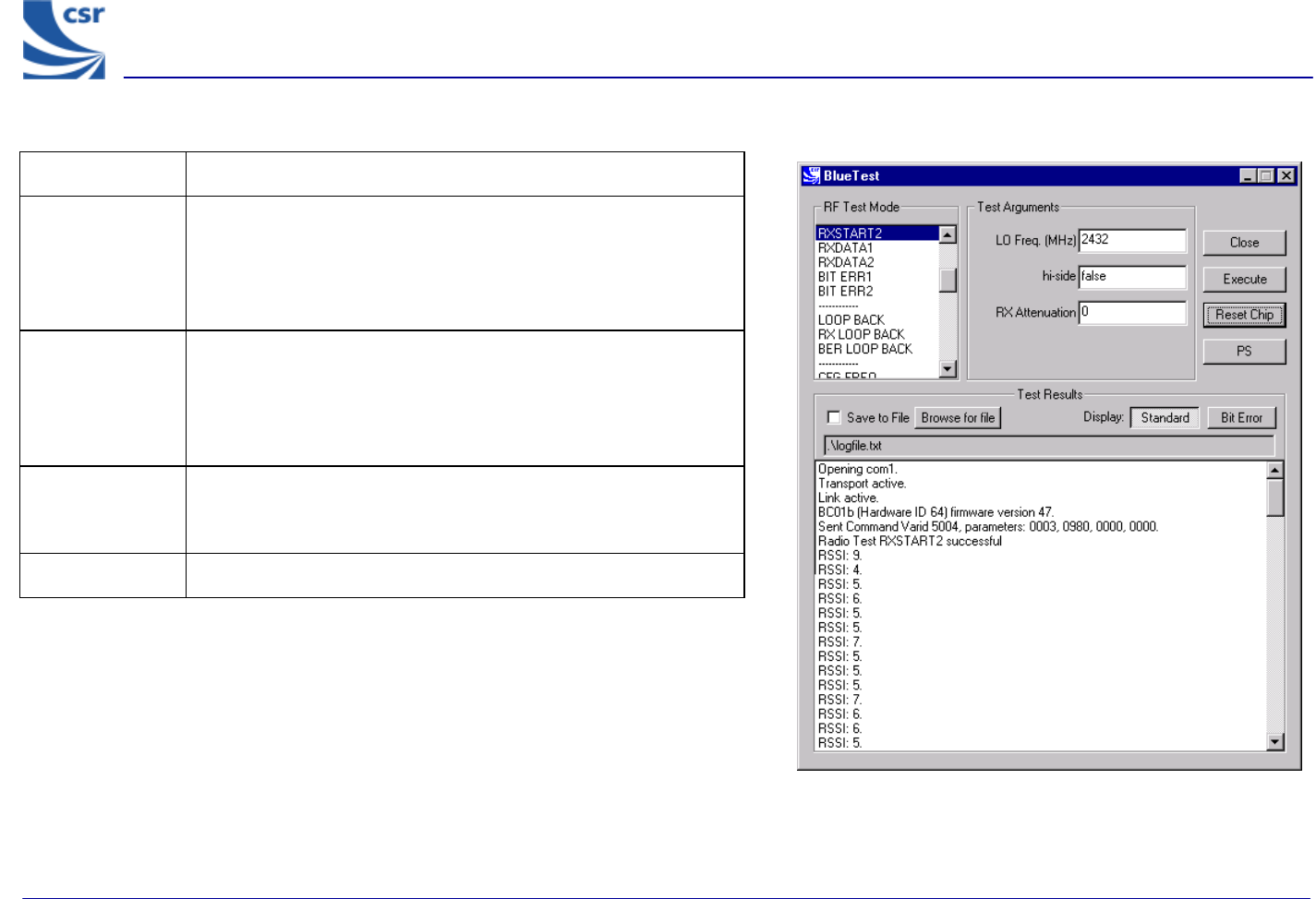
Title RXSTART2
Summary
Enables the receiver in continuous reception, at a designated
frequency (LO Freq), with a choice of low or high side
modulation (hi-side) and with a designated attenuation setting
(RX Attenuation). Digitises the RSSI and sends report regularly to
host. Requires a second unit to be running TXSTART.
Test Arguments
LO Freq (Carrier Frequency MHz) = 2402 to 2480
hi-side (default = false) set 0 or 1
RX Attenuation = 0 to 15 (Default = 0)
Return Data RSSI values, as a uint16, sent over BCSP channel 3 at a rate of
about 10 per second. Can be saved to log file. H4 and USB use
manufacturer’s extensions.
Exit Click on Reset Chip.
RXSTART2 Example Display
BlueTest Instruction Manual
bc01-an-047b
© Copyright CSR Ltd 2001
This material is subject to CSR’s non-disclosure agreement.
Page 10 of 56
BlueCoreTM01
Quantitative Tests
Transmitter Only
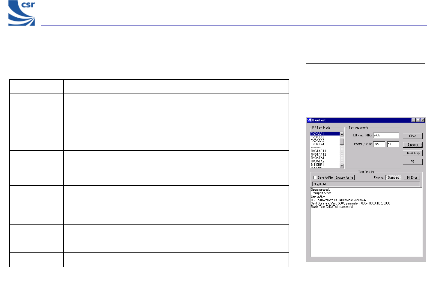
Title TXDATA1
Summary
Enables the transmitter, with a designated frequency (LO Freq) and output Power
(Ext, Int).
Payload is PRBS9 data.
Receiver is not operating.
Packet type and duty cycle can be configured. Refer to Configuration Commands
section.
Related Test
Spec Name
TRM/CA/03/C (power control), TRM/CA/04/C (Tx output spectrum – frequency
range), TRM/CA/05/C (Tx output spectrum – 20dB bandwidth), TRM/CA/06/C
(Adjacent channel power), TRM/CA/08/C (Initial carrier frequency tolerance),
TRC/CA/01/C (Out-of-band spurious emissions).
Test Arguments
LO Freq (Carrier Frequency MHz)= 2402 to 2480
Power (Ext, Int) = gain of external amplifier (if present) and internal amplifier. Ext
value is specific to the design and Int value is 0 to 63 (Default = 50).
Return Data None
Use an RF Analyser to check carrier output.
Exit Click on Reset Chip or select another TXDATA command.
TXDATA1 Example Display
BlueCoreTM01
Quantitative Tests
Transmitter Only
Note: TXDATA and RXDATA require the
same Bluetooth address in each module
for RXDATA to receive data transmitted
by TXDATA. Use CFG_UAP_LAP to set
the address used by the BIST.
BlueTest Instruction Manual
bc01-an-047b
© Copyright CSR Ltd 2001
This material is subject to CSR’s non-disclosure agreement.
Page 11 of 56
BlueCoreTM01
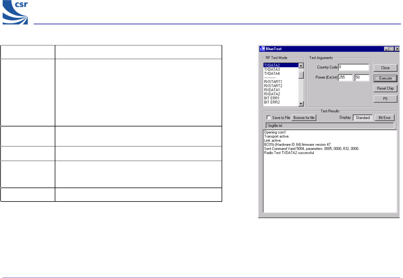
TXDATA2 Example Display
Title TXDATA2
Summary
Enables the transmitter, with a simplified hop sequence
designated by Country Code and sets output Power (Ext, Int).
Payload is PRBS9 data (Default DH1).
Receiver is not operating.
Packet type and duty cycle can be configured. Refer to
Configuration Commands section.
Related Test
Spec Name TRM/CA/01/C (output power), TRM/CA/02/C (power density)
Test Arguments Country Code = 0 to 3 (Default = 0)
Return Data None
Use RF Analyser to check carrier output.
Exit Click on Reset Chip or select another TXDATA command.
BlueTest Instruction Manual
bc01-an-047b
© Copyright CSR Ltd 2001
This material is subject to CSR’s non-disclosure agreement.
Page 12 of 56
BlueCoreTM01
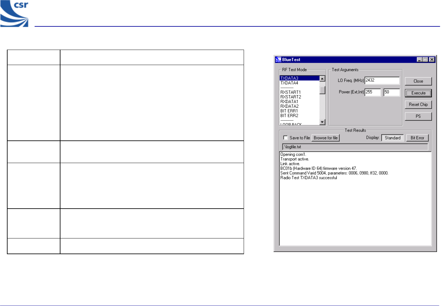
Title TXDATA3
Summary
Enables the transmitter, with a designated frequency (LO
Freq) and output Power (Ext, Int).
Payload is sequence 101010.…
Receiver is not operating.
Packet type and duty cycle can be configured. Refer to
Configuration Commands section.
Related Test
Spec Name TRM/CA/07/C (modulation characteristic), TRM/CA/09/C
(carrier frequency drift)
Test
Arguments
LO Freq (Carrier Frequency MHz)= 2402 to 2480
Power (Ext, Int) = gain of external amplifier (if present) and
internal amplifier. Ext value is specific to the design and Int
value is 0 to 63 (Default = 50).
Return Data None
Use RF Analyser to check out carrier
Exit Click on Reset Chip or select another TXDATA command.
TXDATA3 Example Display
BlueTest Instruction Manual
bc01-an-047b
© Copyright CSR Ltd 2001
This material is subject to CSR’s non-disclosure agreement.
Page 13 of 56
BlueCore
TM
01
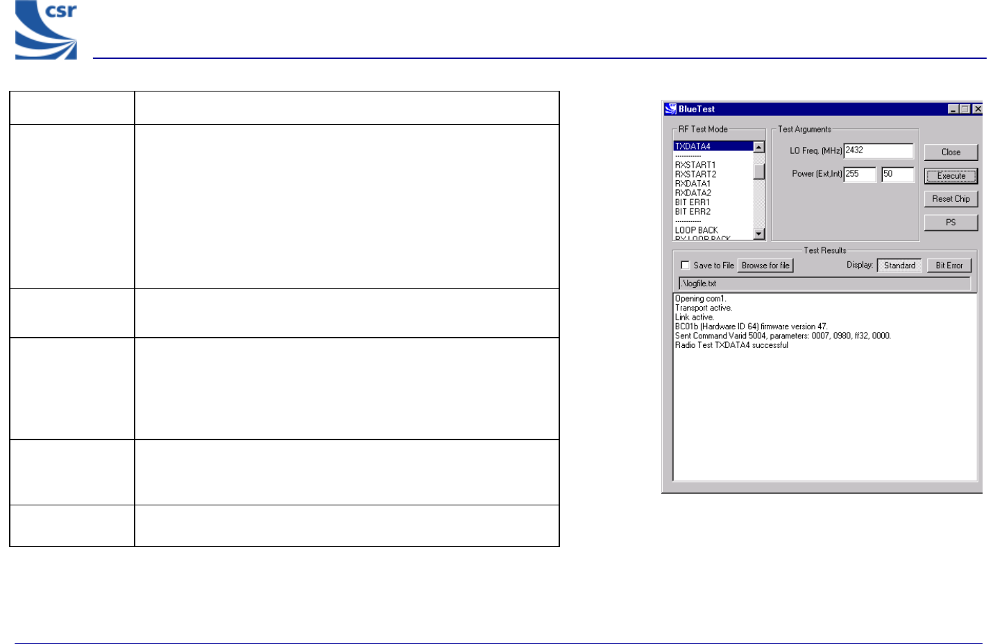
Title TXDATA4
Summary
Enables the transmitter with a designated frequency (LO Freq) and
output Power (Ext, Int).
Payload is sequence 1111000011110000.…
Receiver is not operating.
Packet type and duty cycle can be configured. Refer to
Configuration Commands section.
Related Test
Spec Name TRM/CA/07/C (modulation characteristic), TRM/CA/09/C (carrier
frequency drift)
Test Arguments
LO Freq (Carrier Frequency MHz) = 2402 to 2480
Power (Ext, Int) = gain of external amplifier (if present) and internal
amplifier. Ext value is specific to the design and Int value is 0 to
63 (Default = 50).
Return Data None
Use an RF Analyser to check out carrier.
Exit Click on Reset Chip or select another TXDATA command.
TXDATA4 Example Display
BlueTest Instruction Manual
bc01-an-047b
© Copyright CSR Ltd 2001
This material is subject to CSR’s non-disclosure agreement.
Page 14 of 56
BlueCore
TM
01
Receiver Only
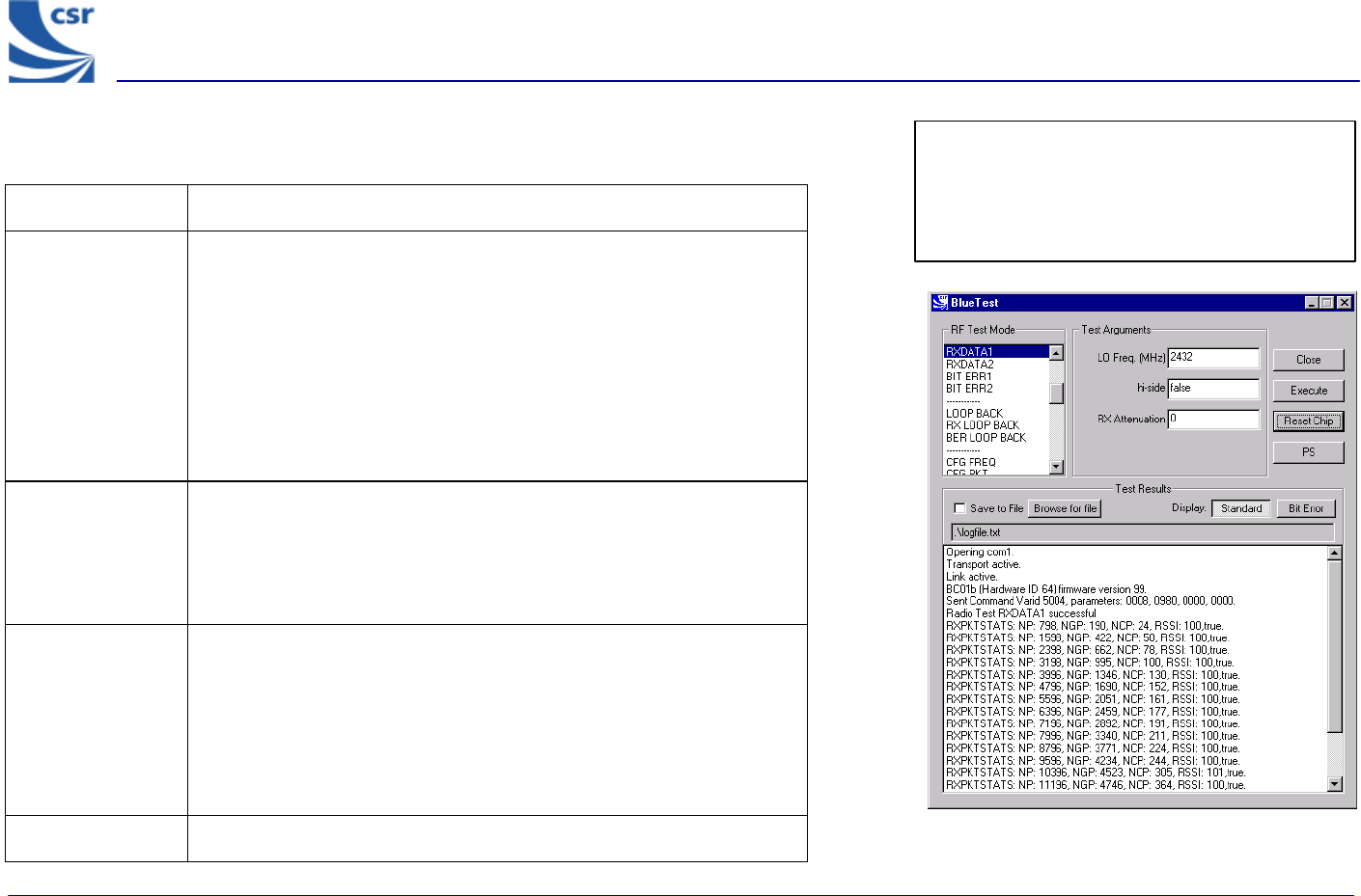
Title RXDATA1
Summary Enables the receiver, at a designated frequency (LO Freq) with a
choice of low or high side modulation (hi-side), and with a designated
attenuation setting (RX Attenuation).
The software counts the number of received packet and the number
of payloads with correctable errors.
The payload itself is thrown away. The time between receive slots and
report frequency can be set. Refer to Configuration Commands
section.
Test Arguments LO Freq (Carrier Frequency MHz)= 2402 to 2480
hi-side = 0 or 1 (default = 0)
RX Attenuation = 0 to 15 (default = 0)
Return data NP = number of packets
NP = number of good packets,
NCP = number of corrected packets
RSSI = value as shown
True = RSSI is reliable, otherwise false
The numbers wrap, rather than being reset to 0.
Exit Click on Reset Chip. RXDATA1 example display
Note: TXDATA and RXDATA require the same
Bluetooth address in each module for RXDATA
to receive data transmitted by TXDATA. Use
CFG_UAP_LAP to set the address used by the
BIST.
BlueTest Instruction Manual
bc01-an-047b
© Copyright CSR Ltd 2001
This material is subject to CSR’s non-disclosure agreement.
Page 15 of 56
BlueCore
TM
01
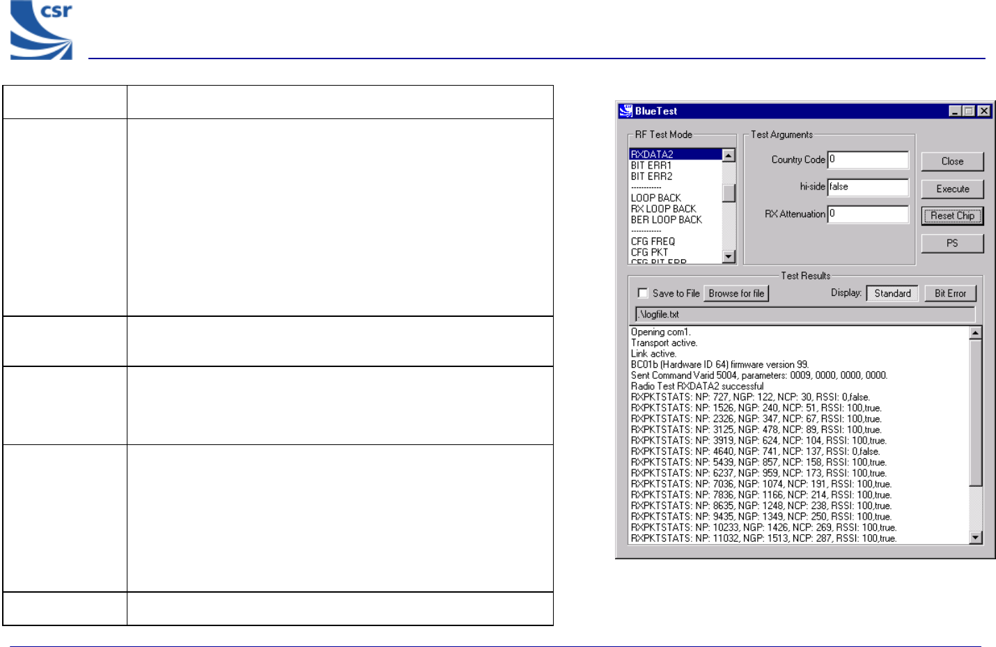
Title RXDATA2
Summary
Enables the receiver with a simplified hop sequence designated
by Country Code, with a choice of low or high side modulation
(hi-side) and with a designated attenuation setting (RX
Attenuation).
The software counts the number of received packets and the
number of payloads with correctable errors.
The payload itself is thrown away. The time between receive slots
and report frequency can be set. Refer to Configuration
Commands Section.
Related Test
Spec Name Standby mode spurious emissions (FCC test)
Test Arguments
Country Code = 0 to 3 (default = 0)
hi-side = 0 or 1 (default = 0)
RX Attenuation = 0 to 15 (default = 0)
Return Data
NP = number of packets
NG = number of good packets
NCP = number of corrected packets
RSSI = value as shown
True = RSSI is reliable, otherwise false
The numbers wrap, rather than being reset to 0.
Exit Click on Reset Chip.
RXDATA2 Example Display
BlueTest Instruction Manual
bc01-an-047b
© Copyright CSR Ltd 2001
This material is subject to CSR’s non-disclosure agreement.
Page 16 of 56
BlueCore
TM
01
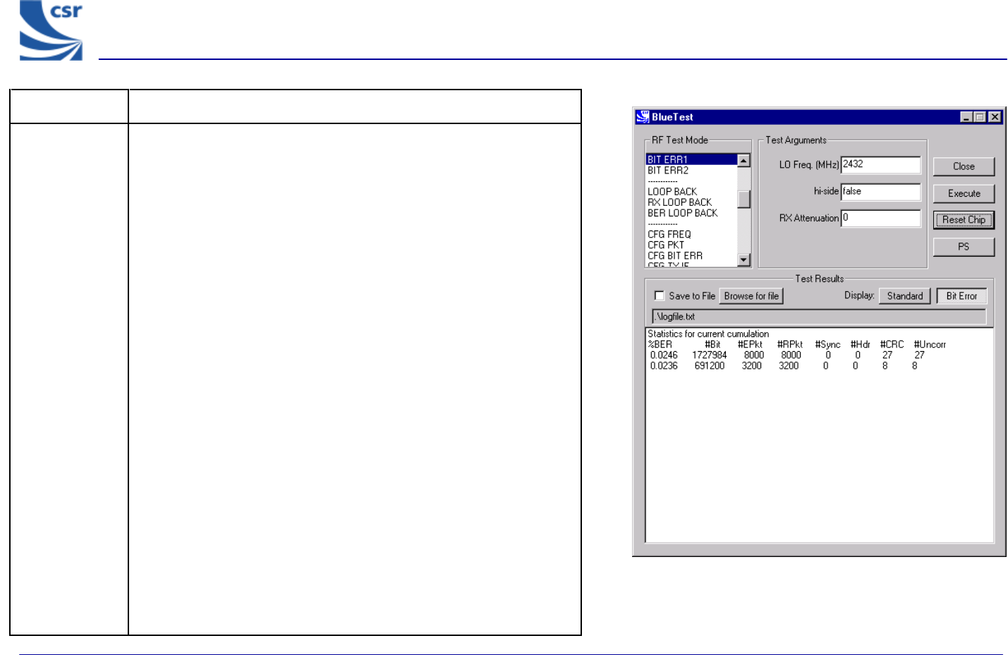
Title BIT ERR1
Summary
Enables the receiver at a designated frequency (LO Freq) with a
choice of low or high side modulation (hi-side) and with a designated
attenuation setting (RX Attenuation).
Returns a set of reports to the host:
g Number of data bits received (payload excluding FEC and CRC)
g Number of data bits that were in error. Assumes PRBS9 data
starting with 1FF in each packet
g Number of packets received
g Number of packets expected, based on txrx_freq (default
12500)
g Number of packets with header errors as reported by hardware
g Number of packets with CRC errors
g Number of packets with uncorrected errors (currently same as
CRC errors)
g Number of sync timeouts. Note that until a transmission is
received a long timeout is used, so this does not reflect the
number of packets expected
Each report has two unint32 values. First is value since last report,
second is summed over the last bits_count (default =
1.6Mbits).
Reports are sent according to report_freq set (default = 1
second). The times between receive slots and report frequency can
be set, and the count reset. Refer to Configuration Commands
section.
BIT ERR1 Example Display
BlueTest Instruction Manual
bc01-an-047b
© Copyright CSR Ltd 2001
This material is subject to CSR’s non-disclosure agreement.
Page 17 of 56
BlueCore
TM
01
Title BIT ERR1 (Continued)
Related Test Spec
Name
RCV/CA/01/C and RCV/CA/02/C (sensitivity), RCV/CA/03/C (C/I
performance), RCV/CA/04/C (blocking performance), RCV/CA/05/C
(intermodulation performance), RCV/CA/06/C (maximum input level)
Test Arguments
LO Freq (Carrier Frequency MHz) = 2402 to 2480
hi-side = 0 or 1 (default = 0)
RX Attenuation = 0 to 15 (default = 0)
Note With a second unit, execute CFG UAP/LAP to set the Bluetooth address.
Execute TXDATA1 then execute CFG UAP/LAP to set the same Bluetooth
address on the Equipment Under Test (EUT) before executing BIT ERR1.
Return Data Eight reports, each two uint32 values (refer to BIT ERR1 Summary).
Exit Click on Reset Chip.
BlueTest Instruction Manual
bc01-an-047b
© Copyright CSR Ltd 2001
This material is subject to CSR’s non-disclosure agreement.
Page 18 of 56
BlueCore
TM
01
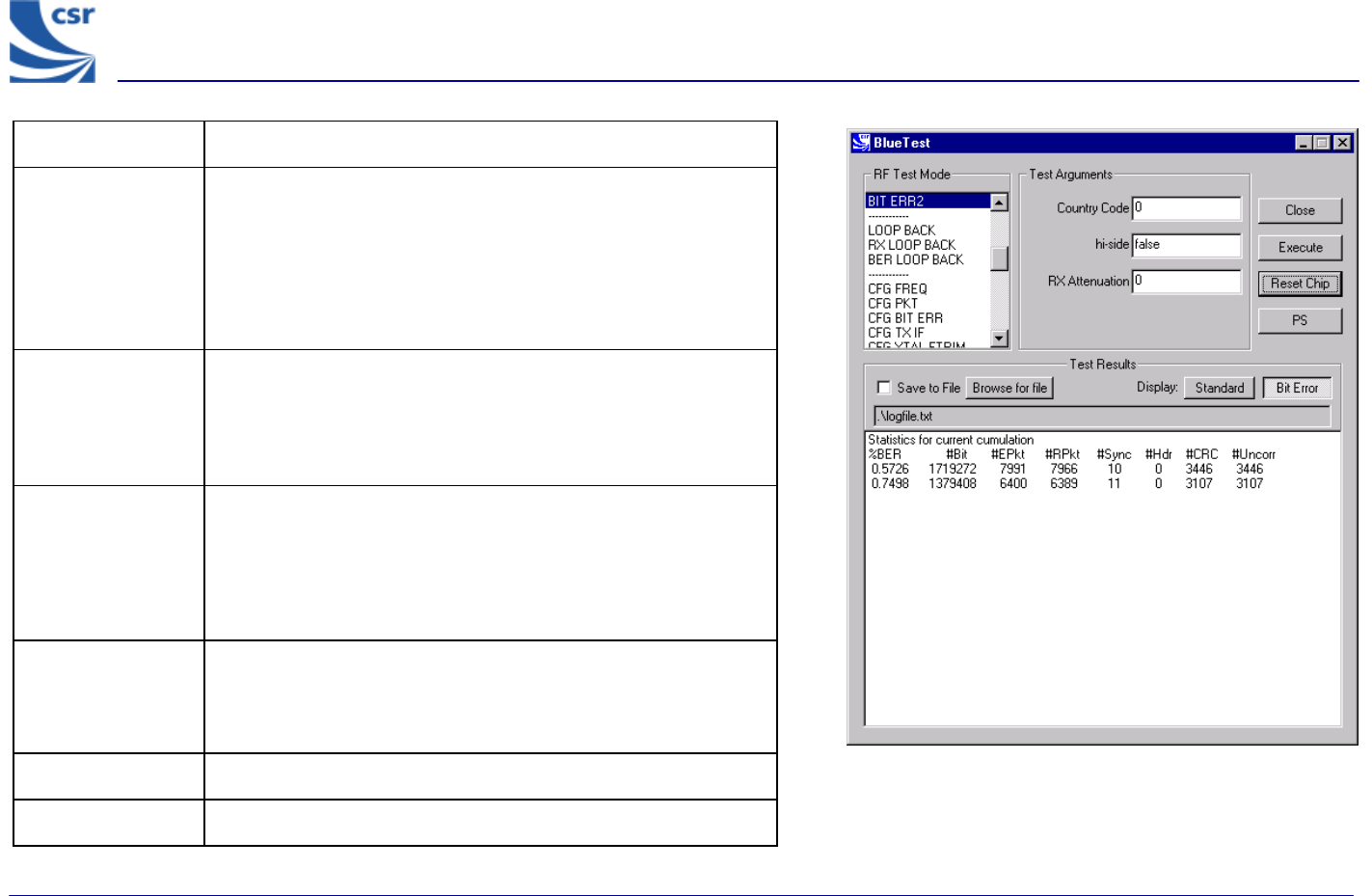
Title BIT ERR2
Summary
Enables the receiver with simplified hopping defined by Country
Code with a choice of low or high side modulation (hi-side), and
with a designated attenuation setting (RX Attenuation) as for
RXDATA2.
Returns information on bit errors to the host as those given for
BIT ERR1.
Related Test Spec
Name
None, but note that this test allows (as in BIT ERR1) the tests
RCV/CA/01/C and RCV/CA/02/C (sensitivity), RCV/CA/04/C
(blocking performance) to be performed with hopping on. This is
a more thorough test than that possible with the 7 Layers
equipment.
Test Arguments
Country Code = 0 to 3 (default 0)
hi-side = 0 or 1 (default = 0)
RX Attenuation = 0 to 15 (default = 0)
Note
With a second unit, execute CFG UAP/LAP to set BT address
then execute TXDATA2, then execute CFG UAP/LAP to set the
same BT address on the Equipment under Test (EUT) before
executing BIT ERR2.
Return Data Nine reports, each two uint32 values as for BIT ERR1.
Exit Click on Reset Chip.
BIT ERR2 Example Display
BlueTest Instruction Manual
bc01-an-047b
© Copyright CSR Ltd 2001
This material is subject to CSR’s non-disclosure agreement.
Page 19 of 56
BlueCore
TM
01
Loopback Test Mode
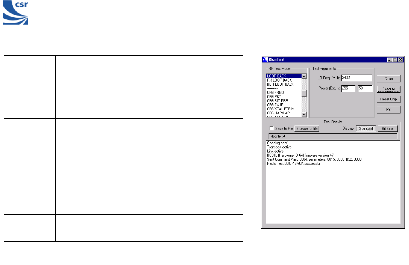
Title LOOP BACK
Summary
Receives data on LO Frequency for data packets and then retransmits
this data on the same channel at transmit level ‘lvl’. Highside
reception is off and attenuation is set to 0. Expected reception
frequency, txrx_freq (default = 12500 microsecs) with single slot
packets returned lb_offs after receipt (default = 1875 microsecs).
Defaults can be changed. See Configuration Commands section.
Related Test
Spec Name
None, but note that this test RCV/CA/01/C to RCV/CA/06/C to be
performed in loopback without using the LMP commanded loopback
test mode.
RCV/CA/01/C to RCV/CA/06/C to be performed in loopback, but
without using the LMP commanded loopback test mode.
Test Arguments
LO Freq (Carrier Frequency MHz)= 2402 to 2480 (default =
2432)
Power (Ext, Int) = gain of external amplifier (if present) and internal
amplifier. Ext value is specific to the design and Int value is 0 to 63
(Default = 50).
Return Data None
Exit Click on Reset Chip.
LOOP BACK Example Display
BlueTest Instruction Manual
bc01-an-047b
© Copyright CSR Ltd 2001
This material is subject to CSR’s non-disclosure agreement.
Page 20 of 56
BlueCore
TM
01
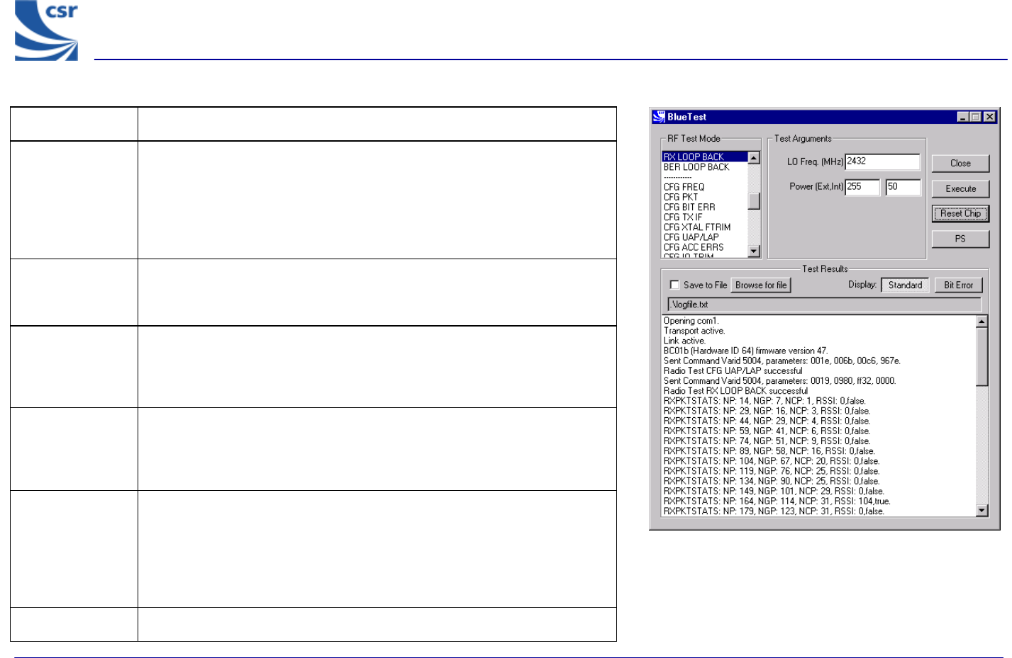
Title RX LOOP BACK
Summary Transmit PRBS9 data on LO Frequency at transmit level and listen for
transmissions in the next slot but one. Sends reports as RXDATA1 back to
the host once per second (configurable). Highside reception is off and
attenuation is set to 0. Default is single-slot packets (configurable with
config_freq). This is designed to be used with a second unit in
LOOP_BACK test mode.
Related Test
Spec Name None, but note that this test allows transmission to and reception from
Implementation under Test (IUT) in LOOP_BACK test mode with RSSI
and BER calculated from FEC.
Test Arguments LO Freq (Carrier Frequency MHz)= 2402 to 2480
Power (Ext, Int) = gain of external amplifier (if present) and internal
amplifier. Ext value is specific to the design and Int value is 0 to 63
(Default = 50).
Note With a second unit execute CFG UAP/LAP to set the Bluetooth address.
Execute LOOP BACK then execute CFG UAP/LAP to set the same BT
address on the Equipment under Test (EUT) before executing RX LOOP
BACK.
Return Data NP = Number of packets
NGP = Number of good packets
NCP = Number of corrected packets
RSSI = Received Signal Strength Indication
True = RSSI is reliable, otherwise false
Exit Click on Reset Chip.
RX LOOP BACK Example Display
BlueTest Instruction Manual
bc01-an-047b
© Copyright CSR Ltd 2001
This material is subject to CSR’s non-disclosure agreement.
Page 21 of 56
BlueCore
TM
01
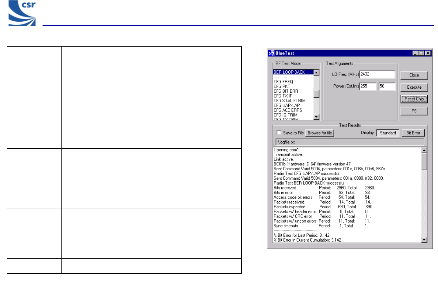
Title BER LOOP BACK
Summary
Transmit PRBS9 data on LO Frequency at transmit level
and listen for transmissions in the next slot but one. Sends
reports as BIT ERR1 back to the host once per second
(configurable). Highside reception is off and attenuation is set to
zero Default is single slot packets (configurable with
config_freq). Designed to be used with a second unit in
loop_back test mode.
Related Test
Spec Name
None, but note that this test allows transmission to and
reception from IUT in loopback test mode, with calculation of
BER to BT specification.
Called via BCSP channel 2
Test Arguments
LO Freq (Carrier Frequency MHz)= 2402 to 2480
Power (Ext, Int) = gain of external amplifier (if present) and
internal amplifier. Ext value is specific to the design and Int
value is 0 to 63 (Default = 50).
Note
With a second unit execute CFG UAP/LAP to set BT address
then execute LOOP BACK, then execute CFG UAP/LAP to set
the same BT address on the EUT before executing BER LOOP
BACK.
Return Data Nine reports as for BIT ERR1.
Exit Click on Reset Chip.
BER LOOP BACK Example Display
BlueTest Instruction Manual
bc01-an-047b
© Copyright CSR Ltd 2001
This material is subject to CSR’s non-disclosure agreement.
Page 22 of 56
BlueCore
TM
01
Configuration Commands
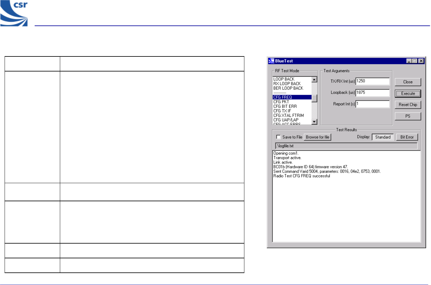
Title CFG FREQ
Summary
Sets three values used in deciding timing details of tests.
Tx/Rx Int (txrx_freq) sets the period in microseconds
between TX and RX events in RXDATA, TXDATA, BIT ERR and
LOOP BACK test modes. Default is 1250 (20 slots), maximum
65536. If passed as 0, current value unchanged.
Loopback (lb_offs) sets the offset in microseconds
between a reception event and retransmission of the data in
loopback. Default is 1875 (two slots later), must be less than
TX/Rx Int (txrx_freq). If passed as zero current value
unchanged.
Report Int(report_freqs) sets the time in seconds between
reports to host sent by RXDATA and BIT ERR functions. Default
1, if passed as 0 current value unchanged.
Related Test
Spec Name None
Test Arguments
TX/RX Int (µS) = 1 to 65535 (default = 1250)
Loopback (µS) = 1 to 65535 (default = 1875)
Report Int (S) = 1 to 65535 (default = 1)
Return Data None.
Exit Click on Reset Chip.
CFG FREQ Example Display
BlueTest Instruction Manual
bc01-an-047b
© Copyright CSR Ltd 2001
This material is subject to CSR’s non-disclosure agreement.
Page 23 of 56
BlueCore
TM
01
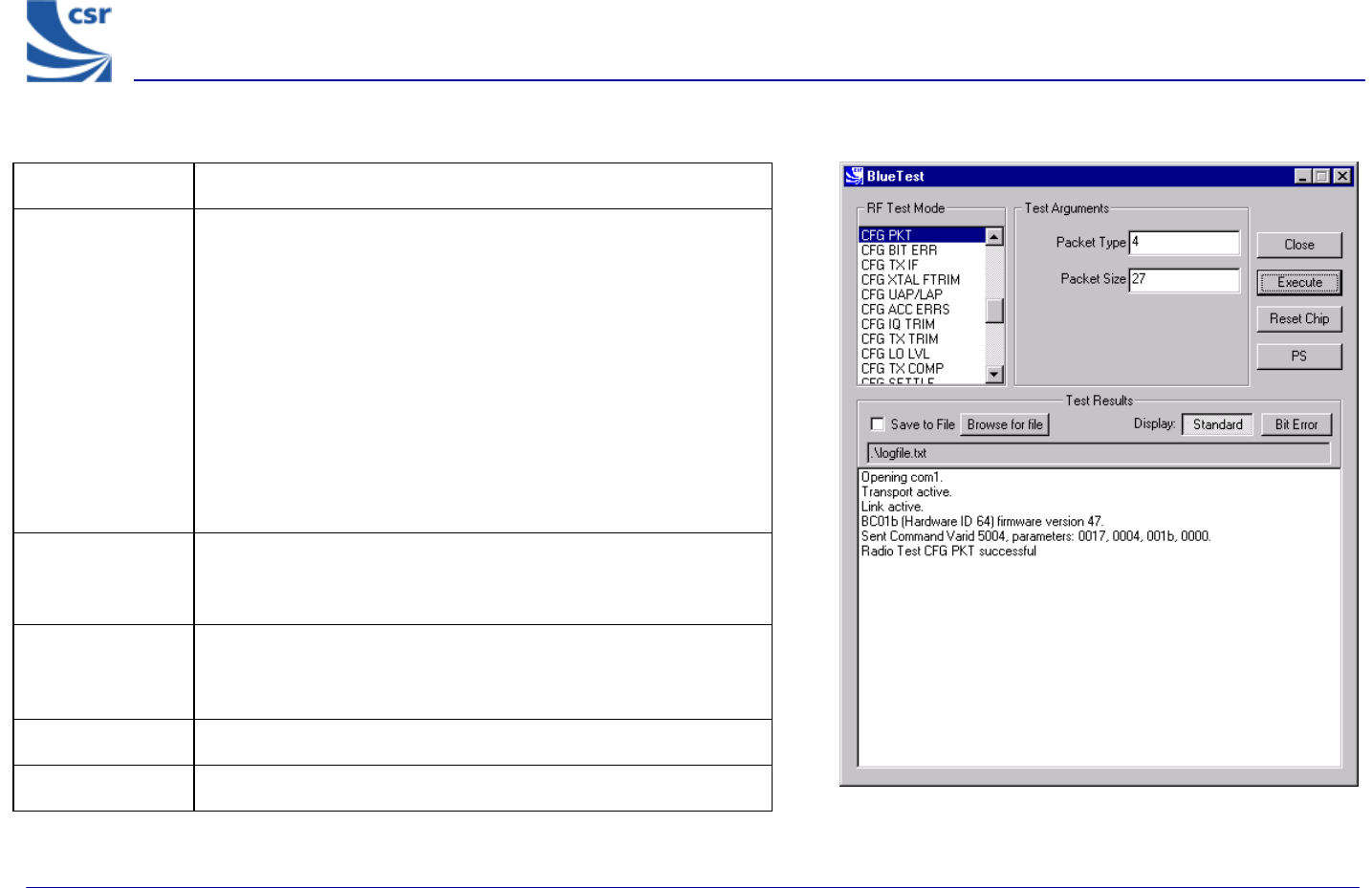
Title CFG PKT
Summary
Sets packet type and size for transmitter tests. It has no effect on
RX or LOOP BACK tests.
Packet Type (pkt-type) is the standard Bluetooth packet
type, 0-15 (12-13 not allowed). Any other number sets default:
DM5 for TXDATA1/2, DH5 for TXDATA3/4.
Packet Size (pkt_size) is the size of data in packet, from one
to maximum for type. If zero sets default: 20 bytes for TXDATA1/2,
192 bytes for TXDATA3/4.
Since the two values are connected both values must be set – no
default is inferred.
Related Test
Spec Name
None
Test Arguments
Packet Type = 0 to 15 (default = 4) (see Appendix 5)
Packet Size = 0 to 339 (default = 27)
Return data None
Exit Click on Reset Chip.
CFG PKT Example Display
BlueTest Instruction Manual
bc01-an-047b
© Copyright CSR Ltd 2001
This material is subject to CSR’s non-disclosure agreement.
Page 24 of 56
BlueCore
TM
01
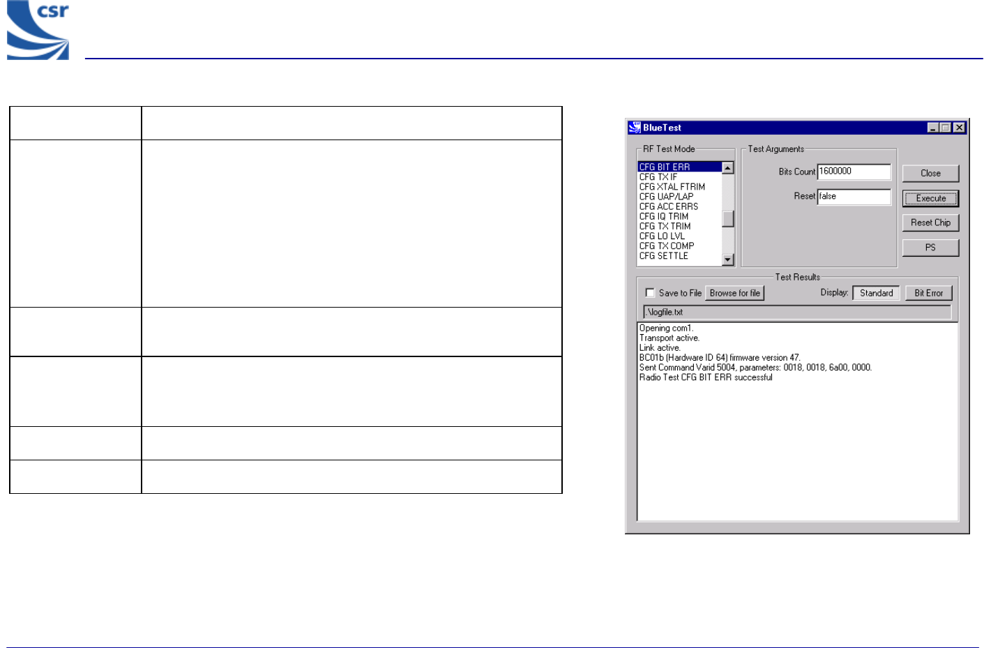
Title CFG BIT ERR
Summary
Sets two values used in bit error measurements.
If Bits Count (bits_count) is non-zero, the target for total
counters is set to this and total count resets at this value. If
passed as 0 current value, unchanged.
If Reset is not false and BIT ERR/2 is active, immediately resets
the counters for the total statistics, but not over the last report
period.
Related Test
Spec Name None
Test Arguments
Bits Count = 1 to 4.2 x 10⁹ (default = 1600000 Bit)
Reset = false (0) or true (1) (default = false)
Return Data None
Exit Click on Reset Chip.
CFG BIT ERR Example Display
BlueTest Instruction Manual
bc01-an-047b
© Copyright CSR Ltd 2001
This material is subject to CSR’s non-disclosure agreement.
Page 25 of 56
BlueCore
TM
01
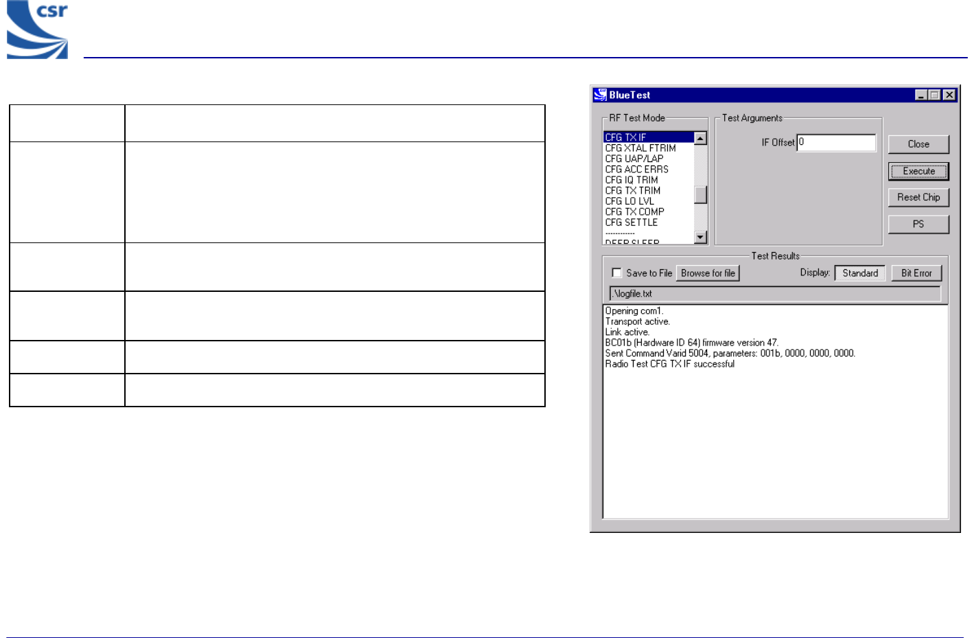
Title CFG TX IF
Summary
Sets the IF frequency used in transmit test modes. The target is
zero, but the stack currently uses a default of -1MHz.
Offset is a signed integer with a range from +5 to –5, in units of
0.5MHz.
Related Test
Spec Name None
Test
Arguments IF Offset = -5 to +5 (default = 0)
Return data None
Exit Click on Reset Chip.
CFG TX IF Example Display
BlueTest Instruction Manual
bc01-an-047b
© Copyright CSR Ltd 2001
This material is subject to CSR’s non-disclosure agreement.
Page 26 of 56
BlueCore
TM
01
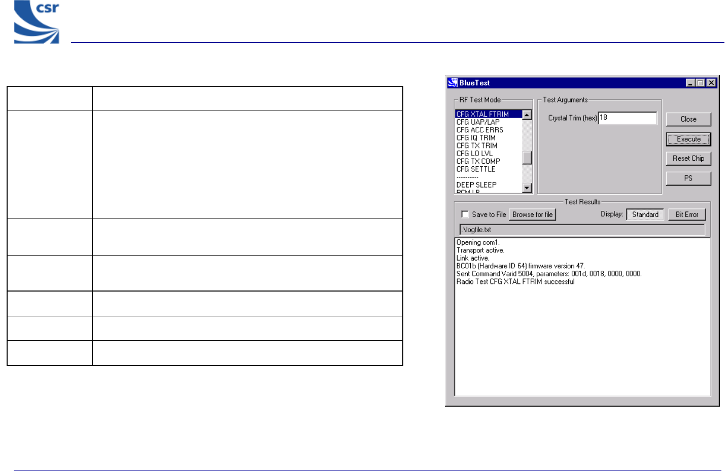
Title CFG XTAL FTRIM
Summary
Timing for BlueCore01 is controlled by a crystal. This requires
trimming for new hardware. This command can be used to set a
new trim value either before a radiotest command is started or
while a test is already in operation; the change takes effect
immediately.
Crystal Trim (xtal_ftrim) is a number between 0 and 63
inclusive. This is not a permanent change.
Related Test
Spec Name None
Test
Arguments Crystal Trim = 0 to 63 (typical = 27)
Note With Crystal Trim set to 0, the current settings will not change.
Return data None
Exit Click on Reset Chip.
CFG XTAL FTRIM Example Display

BlueTest Instruction Manual
bc01-an-047b
© Copyright CSR Ltd 2001
This material is subject to CSR’s non-disclosure agreement.
Page 27 of 56
BlueCore
TM
01
Title CFG UAP/LAP
Summary
Sets the UAP and LAP to be used in tests. BlueCore01 usually
uses its own Bluetooth Device address to determine the access
sync code, as if it is master of a piconet. The UAP and LAP are
the only parts used. This command allows a special UAP and LAP
to be used only in the test modes.
Related Test
Spec Name None
Test Arguments
Bluetooth Address:
UAP = 0 to FF (Default = 6b)
LAP = 0 to FFFFFF (Default = c6967e)
Return Data None
Exit Click on Reset Chip.
CFG UAP/LAP Example Display
BlueTest Instruction Manual
bc01-an-047b
© Copyright CSR Ltd 2001
This material is subject to CSR’s non-disclosure agreement.
Page 28 of 56
BlueCore
TM
01
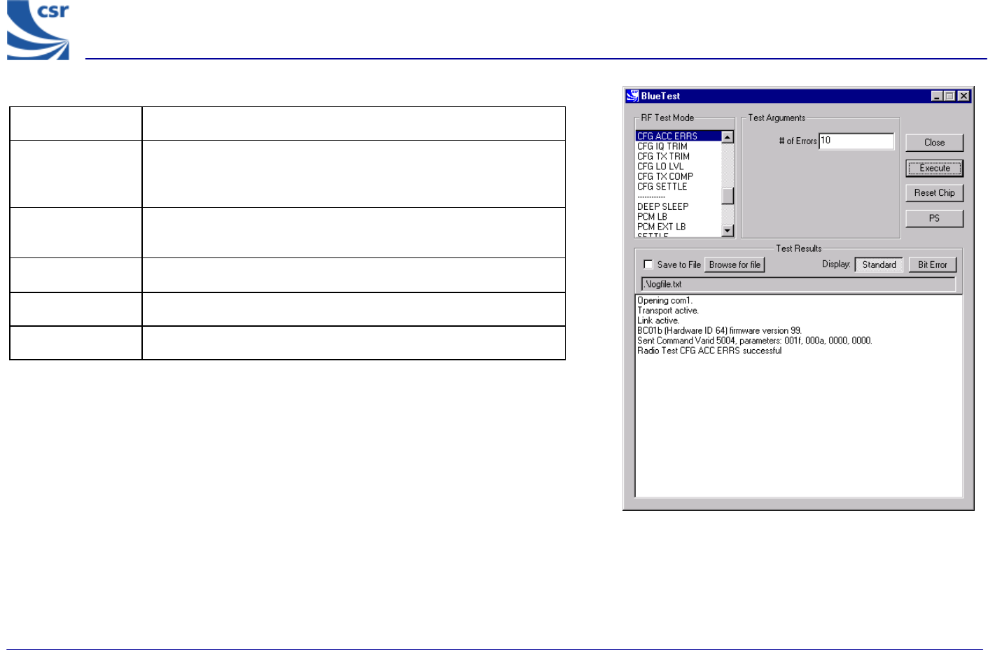
Title CFG ACC ERRS
Summary The receiver uses a sliding correlator to determine that it has
matched the start of a packet. The receiver allows up to # of
errors (n_errs) before a match is rejected.
Related Test
Spec Name None
Test Arguments # of errors = 0 to 15 (default = 10)
Return Data None
Exit Click on Reset Chip.
CFG ACC ERRS Example Display
BlueTest Instruction Manual
bc01-an-047b
© Copyright CSR Ltd 2001
This material is subject to CSR’s non-disclosure agreement.
Page 29 of 56
BlueCore
TM
01
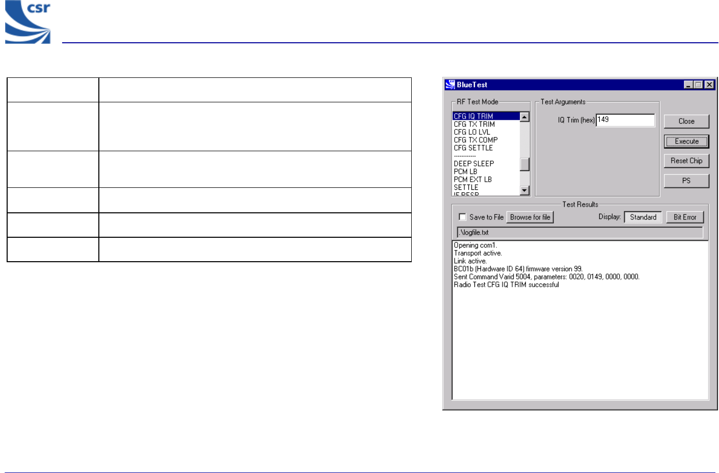
Title CFG IQ TRIM
Summary Sets the IQ Trim (trim) value overriding the value calculated by
the internal calibration algorithm. This command is not executed in
normal use.
Related Test
Spec Name None
Test Arguments IQ Trim = 0 to 511 (default 149 (hex))
Return Data None
Exit Click on Reset Chip.
CFG IQ TRIM Example Display
BlueTest Instruction Manual
bc01-an-047b
© Copyright CSR Ltd 2001
This material is subject to CSR’s non-disclosure agreement.
Page 30 of 56
BlueCore
TM
01
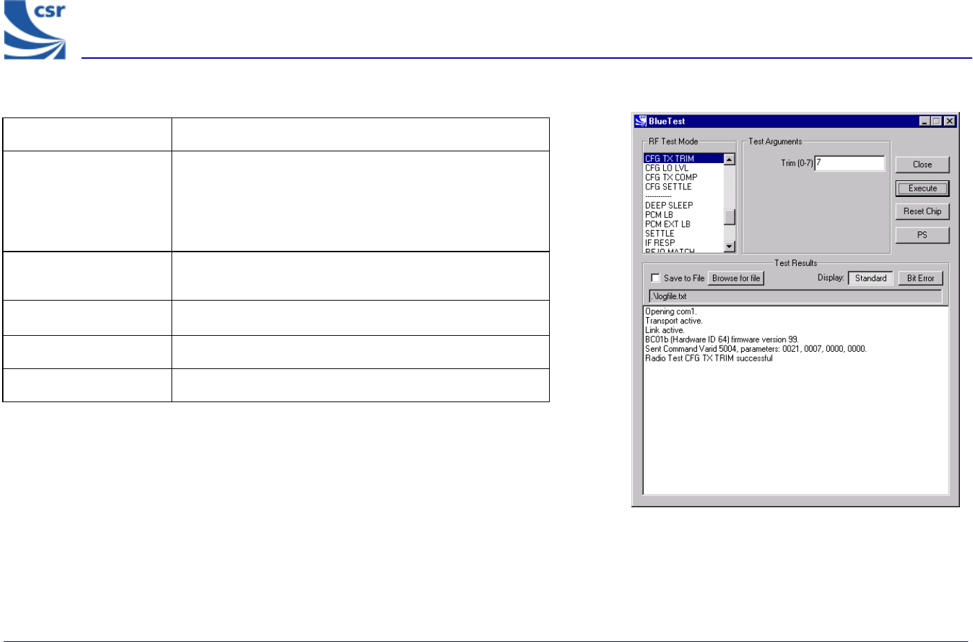
CFG TX TRIM Example Display
Title CFG TX TRIM
Summary
Sets the Active Member Address (am_addr) for the device
to be used in the header of all test transmissions to
am_addr. If the transmitter and receiver are used for the
same test, both devices will normally have to be set to the
same am_addr.
Related Test Spec
Name None
Test Arguments Trim (am_addr) = 0 to 7, Default = 7
Return Data None
Exit Click on Reset Chip.
BlueTest Instruction Manual
bc01-an-047b
© Copyright CSR Ltd 2001
This material is subject to CSR’s non-disclosure agreement.
Page 31 of 56
BlueCore
TM
01
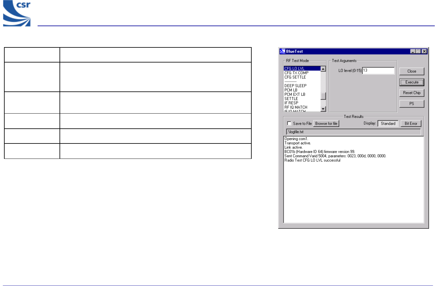
Title CFG LO LVL
Summary Sets the value of the Analogue Local Oscillator output level to LO
level (lvl), overriding the value calculated by the internal
calibration algorithm. This command is not executed in normal use.
Related Test
Spec Name None
Test Arguments LO level = 0 to 15 (default = 13)
Return Data None
Exit Click on Reset Chip.
CFG LO LVL Example Display
BlueTest Instruction Manual
bc01-an-047b
© Copyright CSR Ltd 2001
This material is subject to CSR’s non-disclosure agreement.
Page 32 of 56
BlueCore
TM
01
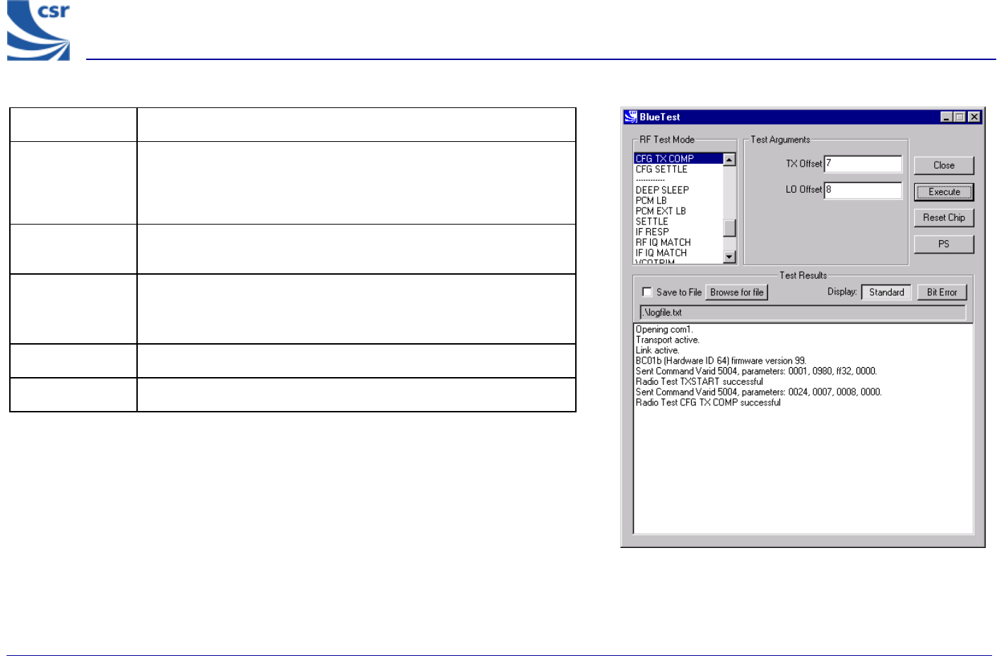
Title CFG TX COMP
Summary
Sets TX Offset (tx_offset) and LO Offset (lo_offset) for the
firmware’s algorithm, which sets the maximum power. Run
TXSTART before executing CFG TX COMP, otherwise there is no
transmit power to set.
Related Test
Spec Name None
Test Arguments
TX Offset, minimum = 0 (default = 7)
LO Offset, minimum = 0 (default = 8)
Return Data None
Exit Click on Reset Chip.
CFG TX COMP Example Display
BlueTest Instruction Manual
bc01-an-047b
© Copyright CSR Ltd 2001
This material is subject to CSR’s non-disclosure agreement.
Page 33 of 56
BlueCore
TM
01
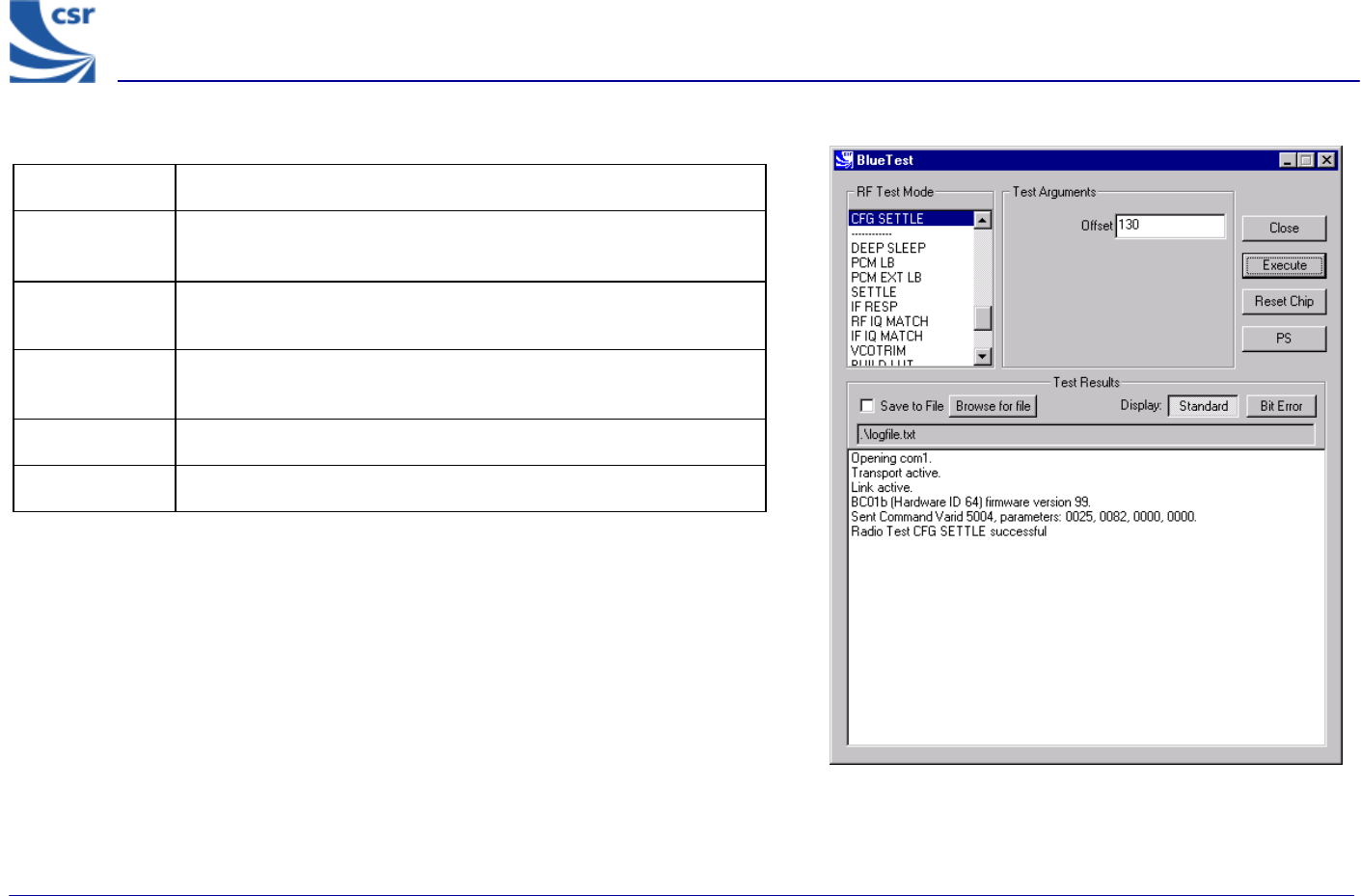
Title CFG SETTLE
Summary Sets the period (radio_on_offset) in microseconds
between turning the radio on and starting to transmit.
Related Test
Spec Name None
Test
Arguments Offset, minimum = 0 (default = 130)
Return Data None
Exit Click on Reset Chip.
CFG SETTLE Example Display
BlueTest Instruction Manual
bc01-an-047b
© Copyright CSR Ltd 2001
This material is subject to CSR’s non-disclosure agreement.
Page 34 of 56
BlueCore
TM
01
Built-in-Self Test (BIST) Routines
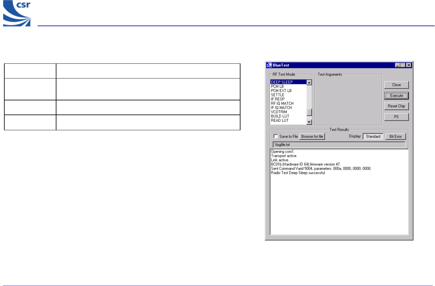
Title Deep Sleep
Summary Puts the chip into deep-sleep after a delay of half a second until
woken by reset or any activity on USB or UART interface.
Return Data None
Exit Click on Reset Chip or another routine being called.
Deep Sleep Example Display

BlueTest Instruction Manual
bc01-an-047b
© Copyright CSR Ltd 2001
This material is subject to CSR’s non-disclosure agreement.
Page 35 of 56
BlueCore
TM
01
Title PCM LB
Summary
Sets the PCM into LOOP BACK mode, whereby the data read from
the PCM input is output again on the PCM out pin. The LOOP BACK
is via software and the buffers so there is a pipeline delay. The PCM
port mode is selectable.
If PCM Mode = 0, BlueCore01 is slave in normal 4-wire
configuration
If PCM Mode = 1, BlueCore01 is master in normal 4-wire
configuration
If PCM Mode = 2, BlueCore01 is master in Manchester encoded,
2-wire configuration.
Test
Arguments PCM Mode = 0 to 2 (default = 1)
Return Data None
Exit Click on Reset Chip or another routine being called.
PCM LB Example Display
BlueTest Instruction Manual
bc01-an-047b
© Copyright CSR Ltd 2001
This material is subject to CSR’s non-disclosure agreement.
Page 36 of 56
BlueCore
TM
01
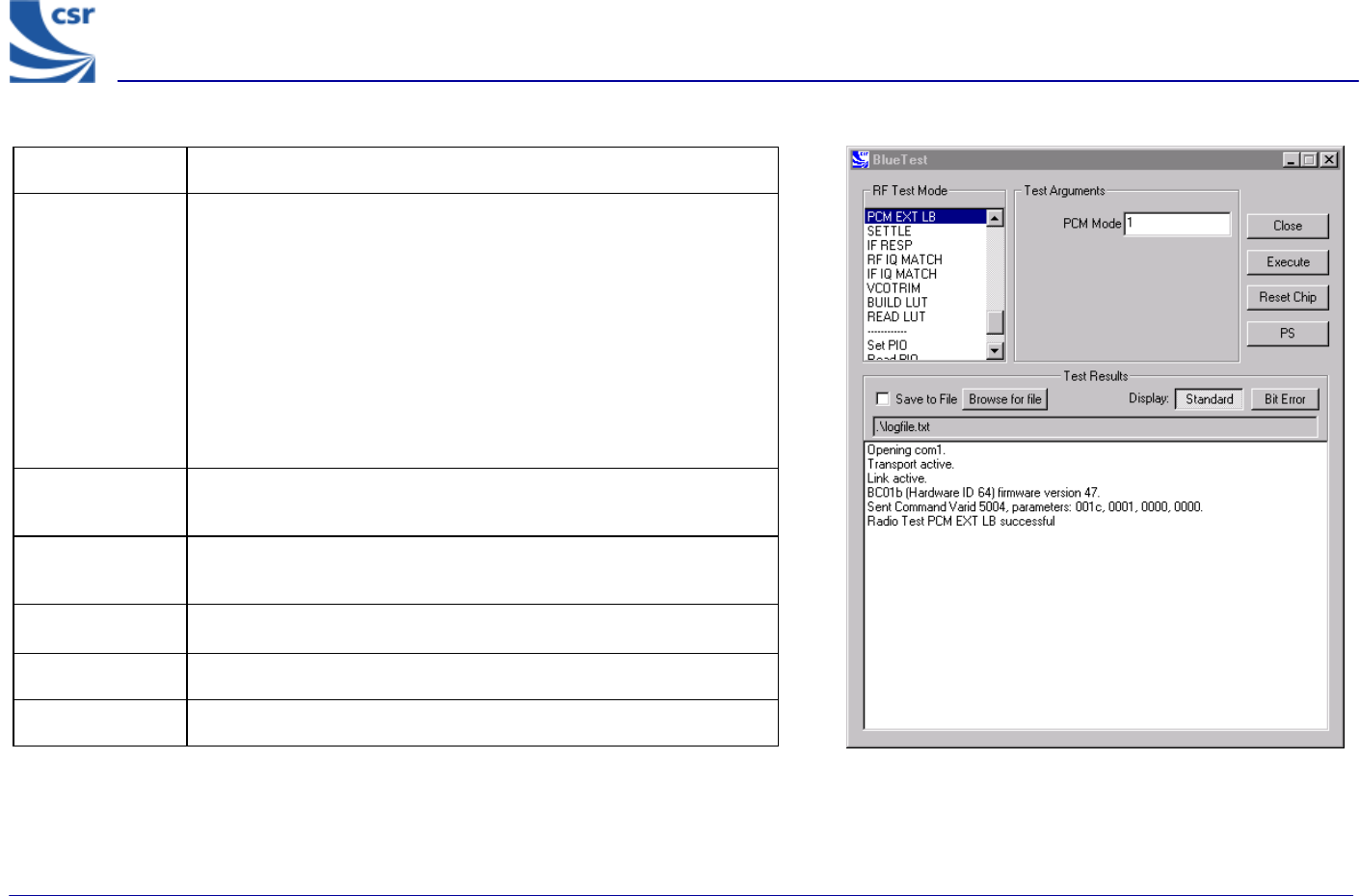
Title PCM EXTERNAL LOOPBACK
Summary
Sets the PCM into external LOOPBACK mode, whereby the data
written to the PCM output is read again on the input pin. A check is
made that the data read back is the same (up to usual codec
transformations) as that written. The LOOP BACK consists of 512
bytes of random data.
The PCM port mode is selectable as PCM Mode (pcm_mode),
which is the same as for PCM LB
(radiotest_pcm_loop_back)
The external LOOP BACK may be a simple wire.
Related Test
Spec Name None
Note On the Casira under test, set CN8 jumper to Codec BYP and on
header CN12 link pins 10 and 11.
Test Arguments PCM Mode = 0 to 2 (default = 1)
Return Data None
Exit Click on Reset Chip.
PCM EXT LB Example Display
BlueTest Instruction Manual
bc01-an-047b
© Copyright CSR Ltd 2001
This material is subject to CSR’s non-disclosure agreement.
Page 37 of 56
BlueCore
TM
01
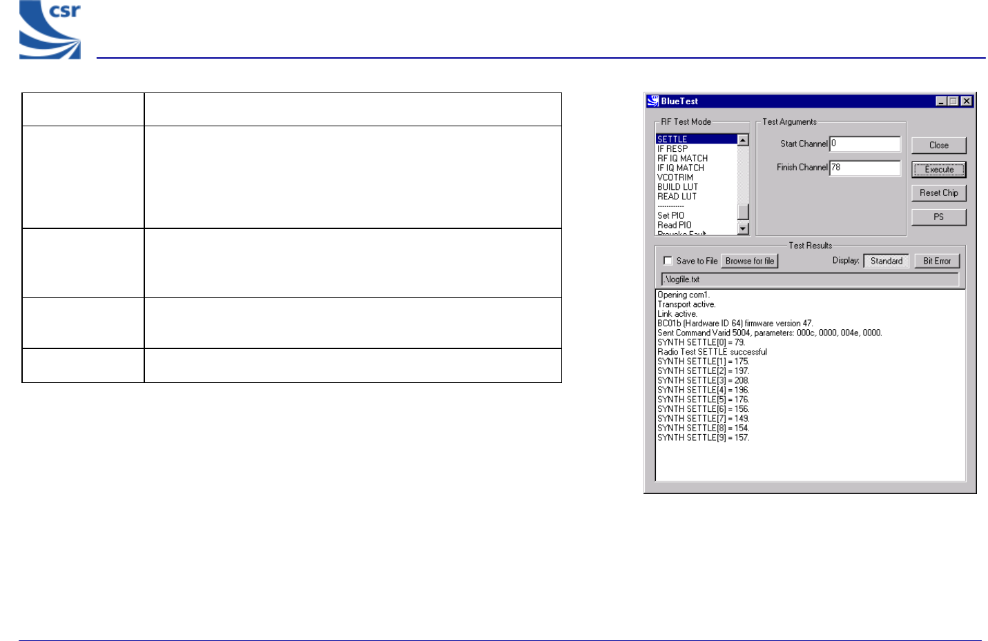
Title SETTLE
Summary
Builds the LUT as normal, then does a step from Start Channel
(chan1) to Finish Channel (chan2), while the synthesiser is
running. It digitises the synthesiser (LO_TUNE) error
voltage at intervals of 10 – 20µs over the next 200µs and
writes the results to an array.
Test Arguments
Start Channel (chan1) = 0 to 78 (default 0)
Finish Channel (chan2) = 0 to 78 (default 78)
Return Data A sequence of ten reports of the synthesiser (LO_TUNE) error
voltage over the next 200µs.
Exit Click on Reset Chip or another routine being called.
SETTLE Example Display
BlueTest Instruction Manual
bc01-an-047b
© Copyright CSR Ltd 2001
This material is subject to CSR’s non-disclosure agreement.
Page 38 of 56
BlueCore
TM
01
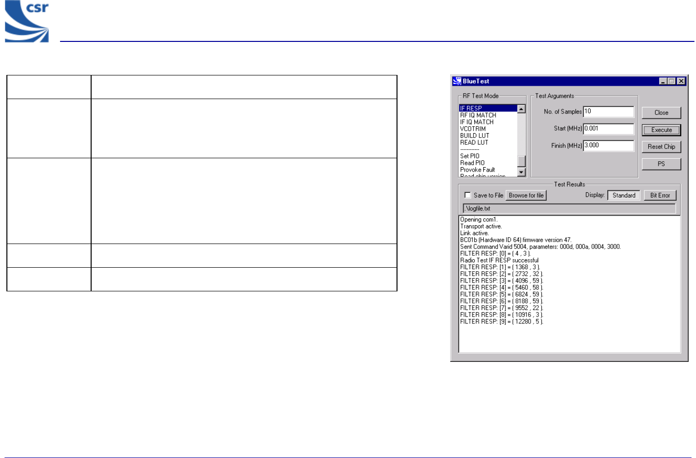
Title IF RESP
Summary
Sweeps transmit IF carrier frequency over designated number of
samples (n_samples) within range (0-3MHz maximum) and
measures RSSI. Returns table of RSSI value against frequency
offset to characterise IF filter response.
Test
Arguments
No. of Samples(n_samples) = 0 to 65535 (default = 10)
Start (lo_offset) = 0 to 3MHz (default 0.001 MHz)
Finish (hi_offset) = 0 to 3 MHz (default = 3.000
MHz. Must be greater than lo_offset)
Return Data A sequence of reports of RSSI and frequency offset.
Exit Click on Reset Chip.
IF RESP Example Display
BlueTest Instruction Manual
bc01-an-047b
© Copyright CSR Ltd 2001
This material is subject to CSR’s non-disclosure agreement.
Page 39 of 56
BlueCore
TM
01
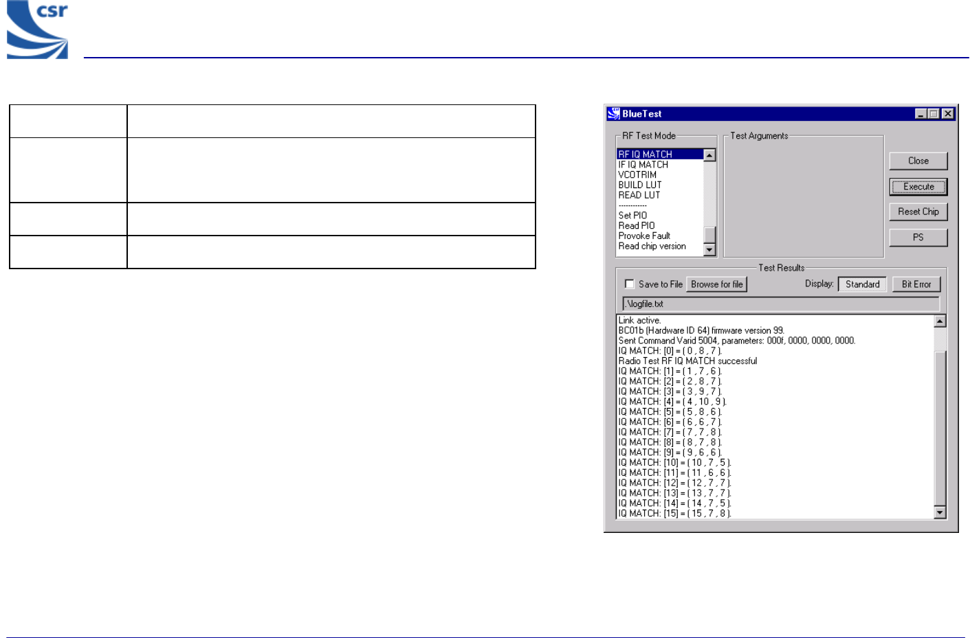
Title RF IQ MATCH
Summary Measures RF IQ match by injecting test signal, sweeping IQ trim
and measuring RSSI for on-channel and image. Returns array of
IQ measurements against IQ trim.
Return Data An array of 16 IQ measurements against IQ trim.
Exit Click on Reset Chip.
RF IQ MATCH Example Display
BlueTest Instruction Manual
bc01-an-047b
© Copyright CSR Ltd 2001
This material is subject to CSR’s non-disclosure agreement.
Page 40 of 56
BlueCore
TM
01
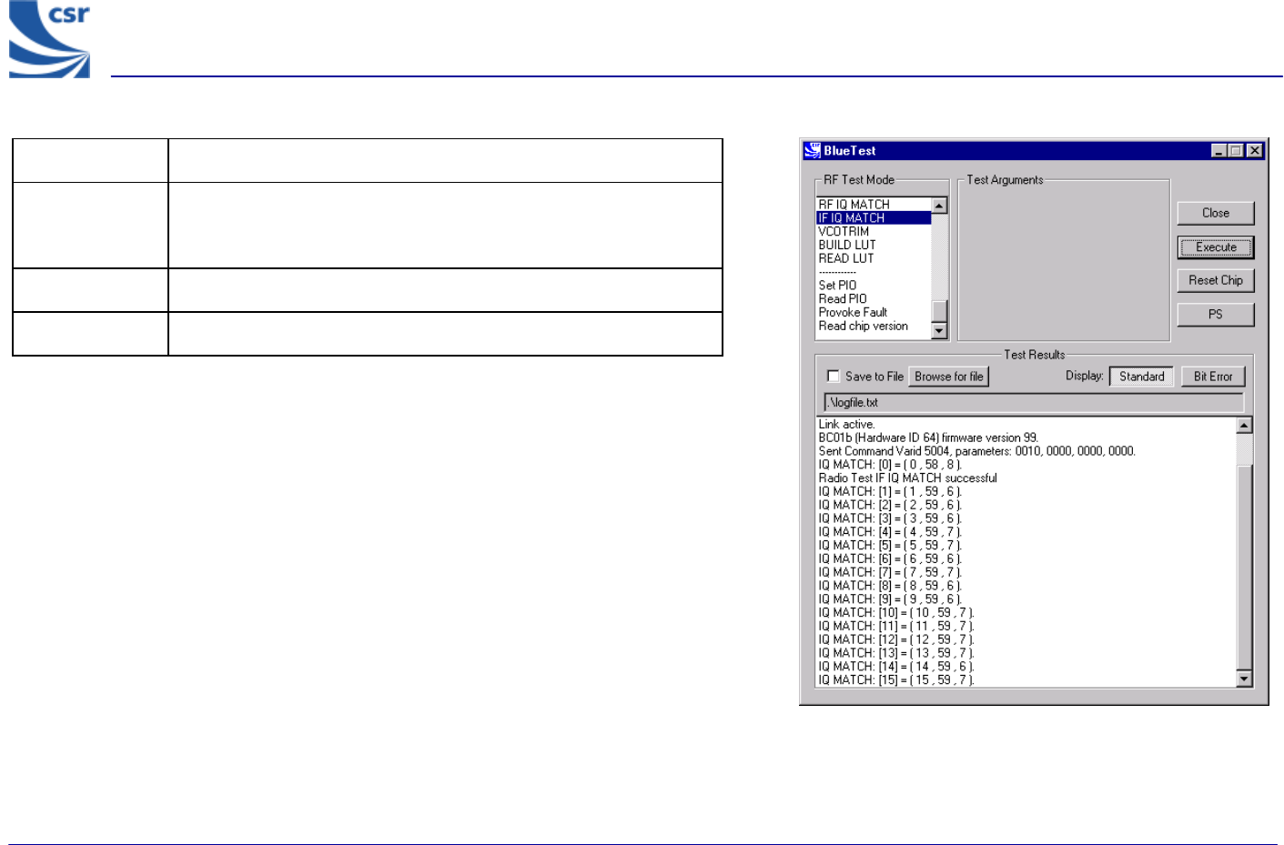
Title IF IQ MATCH
Summary Measures IF IQ match by injecting test signal, sweeping IQ trim
and measuring RSSI for on-channel and image. Returns array of
IQ measurements against IQ trim.
Return Data An array of 16 IQ measurements against IQ trim.
Exit Click on Reset Chip.
IF IQ MATCH Example Display
BlueTest Instruction Manual
bc01-an-047b
© Copyright CSR Ltd 2001
This material is subject to CSR’s non-disclosure agreement.
Page 41 of 56
BlueCore
TM
01
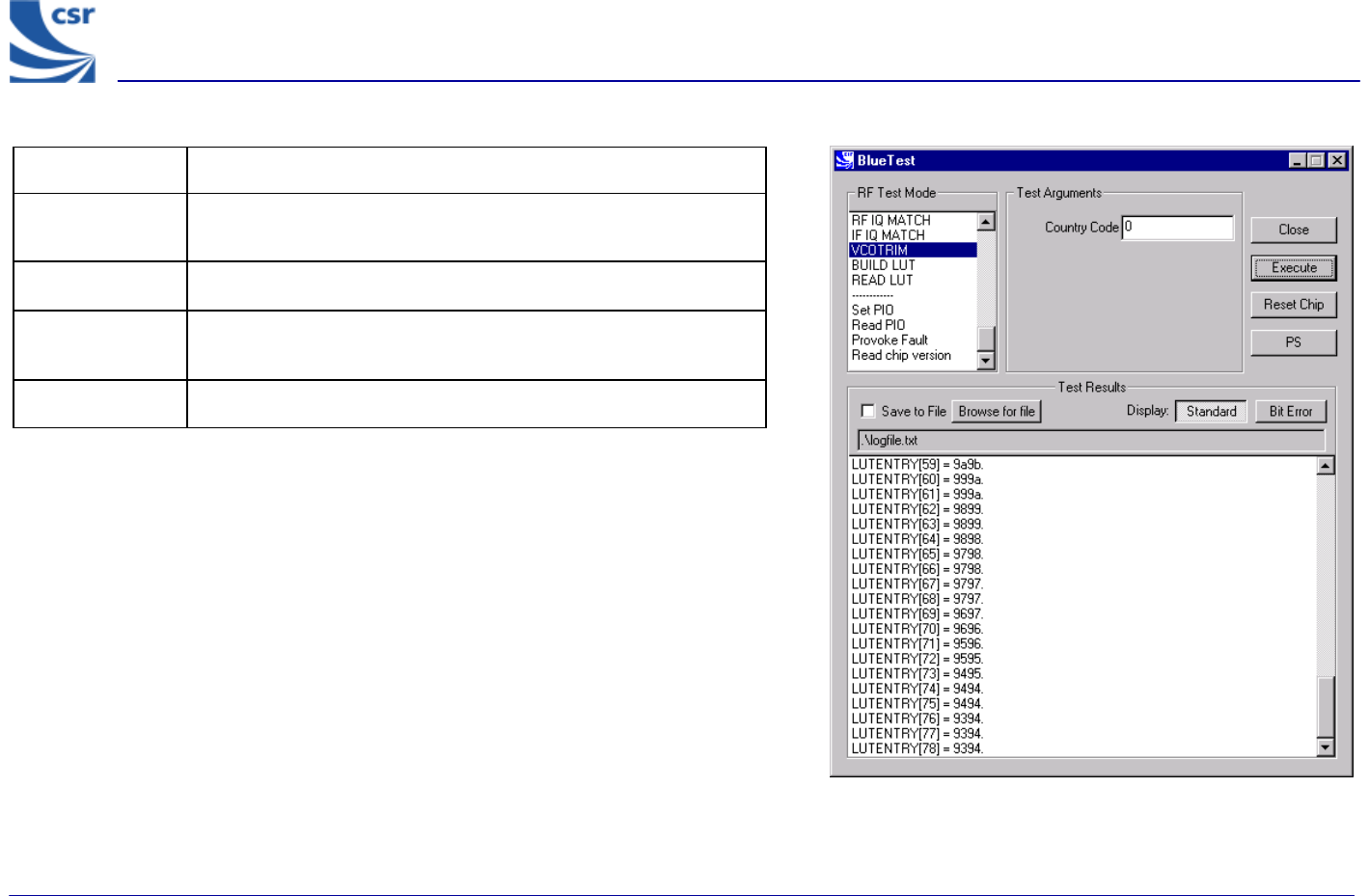
Title VCO TRIM
Summary Produces look up table of VCO trim versus hop frequencies for a
designated country hop sequence.
Test Arguments Country Code (cc) = 0 to 3 (default = 0)
Return Data An array of 79 values for VCO trim if Country Code is 0
otherwise 23 values.
Exit Click on Reset Chip.
VCO TRIM Example Display
BlueTest Instruction Manual
bc01-an-047b
© Copyright CSR Ltd 2001
This material is subject to CSR’s non-disclosure agreement.
Page 42 of 56
BlueCore
TM
01
Miscellaneous Test Routines
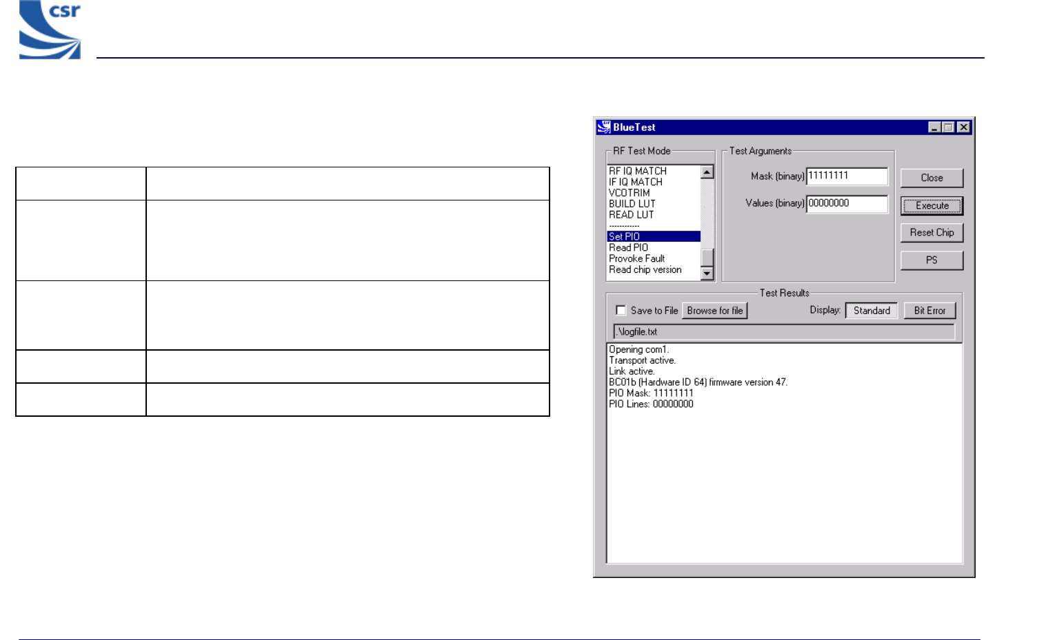
Title Set PIO
Summary
Enables designated PIO lines as outputs and sets them as
desired. To be used with caution since it over-rides previous
settings. Bit 0 corresponds to PIO[0], and a logic one enables it
as an output.
Test Arguments
Mask (default = 11111111)
Values (default = 00000000)
Return Data None
Exit Click on Reset Chip.
Set PIO Example Display
BlueTest Instruction Manual
bc01-an-047b
© Copyright CSR Ltd 2001
This material is subject to CSR’s non-disclosure agreement.
Page 43 of 56
BlueCore
TM
01
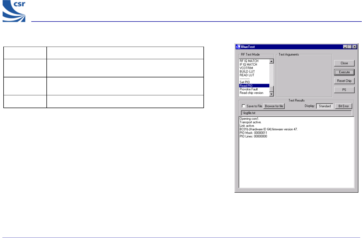
Title Read PIO
Summary Reads the logic state of the PIO pins. Valid whether they are
inputs or outputs.
Return Data PIO Lines (uint8) sent over BCSP channel 3, giving the logic level
at each of the pins.
Exit Click on Reset Chip.
READ PIO Example Display
BlueTest Instruction Manual
bc01-an-047b
© Copyright CSR Ltd 2001
This material is subject to CSR’s non-disclosure agreement.
Page 44 of 56
BlueCore
TM
01
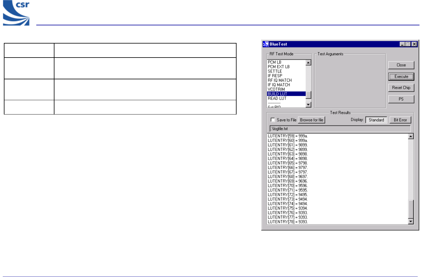
Title BUILD LUT
Summary Builds the radio’s channel LO_TRIM frequency look-up table then
returns it to the host.
Return Data A sequence of 79 uint16 numbers, containing the calibration data
just generated.
Exit Click on Reset Chip.
BUILD LUT Example Display
BlueTest Instruction Manual
bc01-an-047b
© Copyright CSR Ltd 2001
This material is subject to CSR’s non-disclosure agreement.
Page 45 of 56
BlueCore
TM
01
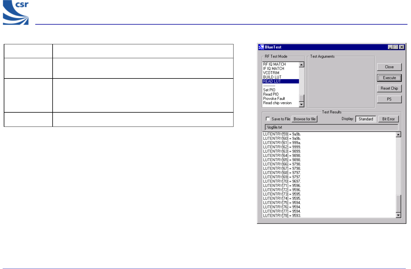
Title READ LUT
Summary Reports the radio’s channel LO_TRIM frequency look-up-table
(LUT) to the host.
Return Data
A sequence of 79 (uint16) numbers containing the contents of the
look up table (LUT) for Europe and North America or a sequence of
23 (uint16) numbers for other countries. The upper byte contains
the transmitter trim and the lower byte contains the receiver trim.
Exit Click on Reset Chip.
READ LUT Example Display
BlueTest Instruction Manual
bc01-an-047b
© Copyright CSR Ltd 2001
This material is subject to CSR’s non-disclosure agreement.
Page 46 of 56
BlueCore
TM
01
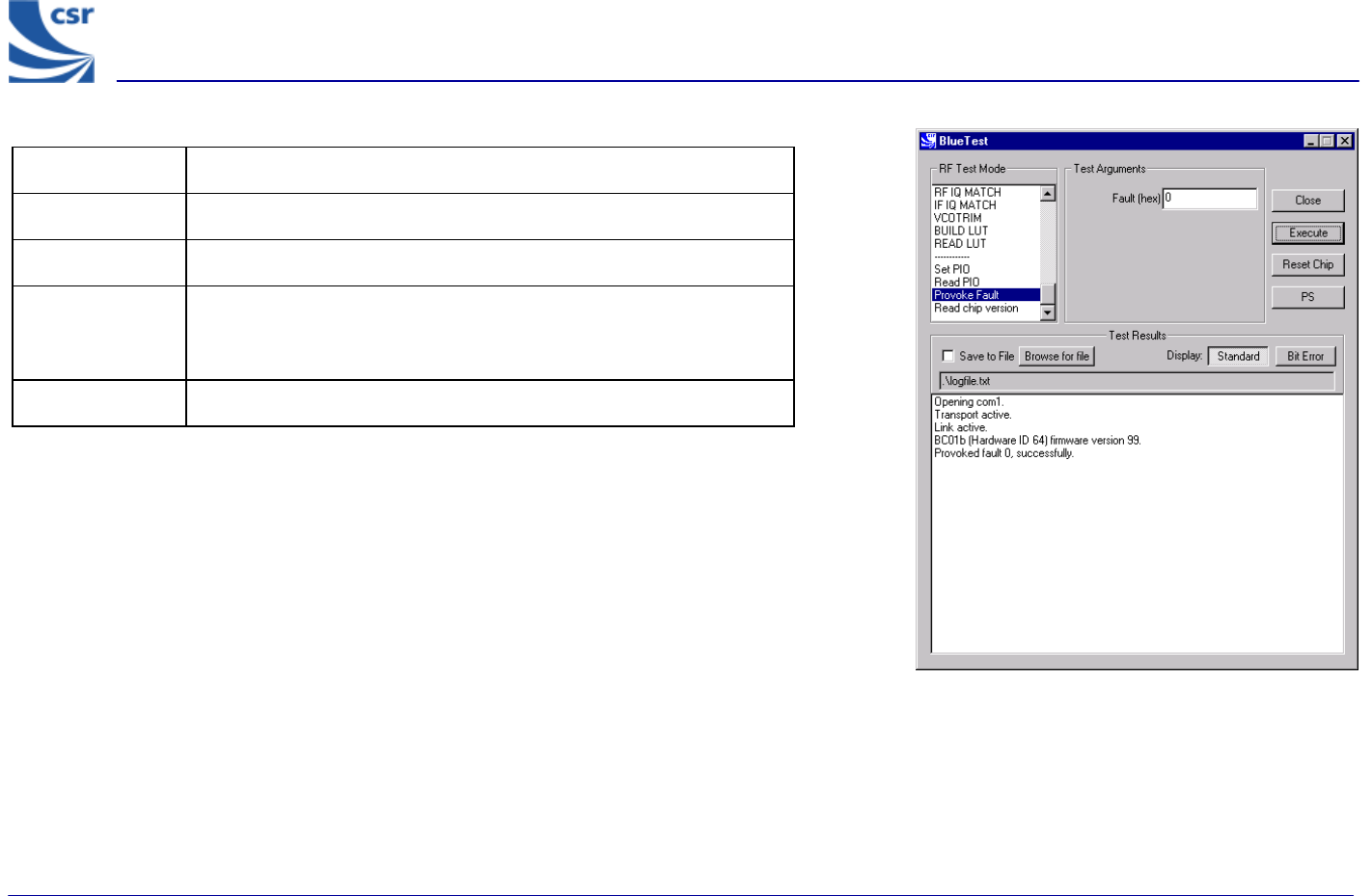
Title PROVOKE FAULT
Summary Provokes a fault mode in the on-chip processor.
Return Data None
Test Arguments Fault (hex) = 0 to 2b (default = 0)
Note: Contact CSR for more information about using fault modes.
Exit Click on Reset Chip.
PROVOKE FAULT Example Display
BlueTest Instruction Manual
bc01-an-047b
© Copyright CSR Ltd 2001
This material is subject to CSR’s non-disclosure agreement.
Page 47 of 56
BlueCore
TM
01
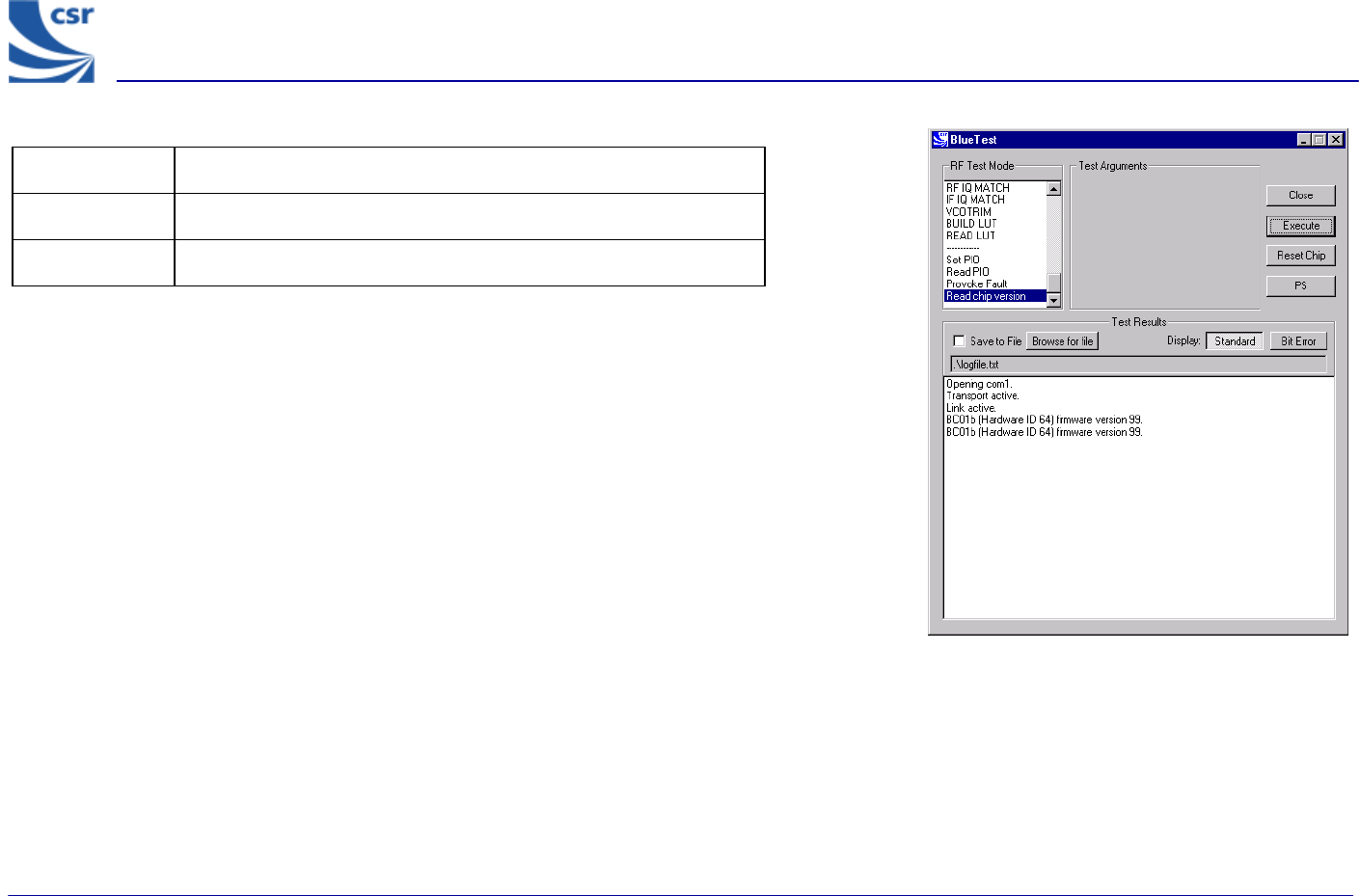
Title READ CHIP VERSION
Summary Reads the hardware ID and firmware version of device.
Return data Hardware ID and firmware version.
READ CHIP VERSION Example Display
BlueTest Instruction Manual
bc01-an-047b
© Copyright CSR Ltd 2001
This material is subject to CSR’s non-disclosure agreement.
Page 48 of 56
BlueCore
TM
01
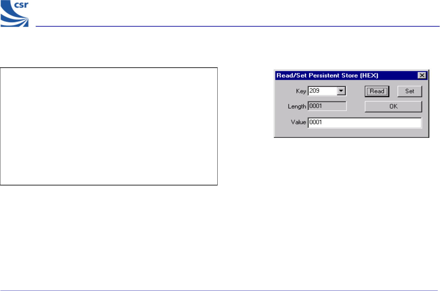
Persistent Store Keys
Select PS from the main menu.
Enter a Key number.
To read a PS Key value, click on Read. The setting displays in the Value
field.
To change a PS key setting, enter a different value in the Value field and
click on Set.
To exit, click on OK.
PERSISTENT STORE KEY Example Display
BlueTest Instruction Manual
bc01-an-047b
© Copyright CSR 2001
This material is subject to CSR’s non-disclosure agreement. Page 49 of 56
BlueCore
TM
01
Appendix 1
BIST Parameters
Name Type Min Max Meaning
lo_freq uint16 2402 2480 Bluetooth channel frequency in MHz
lxlvl uint16 0 63 Internal amplifier power setting. Use
50 for maximum power
mod_freq uint16 0 65535 Modulation frequency for modulated
carrier transmit test in units of 1/4096
MHz
highside bool 0 Non-
zero Receive IF setting, use false (0)
rx_attn uint16 0 15 Initial attenuation setting, overwritten
by AGC
country_code uint16 0 3 Simplified hop sequence code, use
country_code 0 for 79 hops
txrx_freq uint16 1 65535 Period in microseconds between RX
and TX events; default 12500 (20
slots)
lb_offs uint16 1 65535 Offset in microseconds between
receive and transmit in loopback
report_freq uint16 1 65535 Time in seconds between reports to
host, default 1
pkt_type uint16 0 15 Standard Bluetooth packet type (12-
13 disallowed. 0, 1, 2 not useful)
pkt_size uint16 0 339 Size of payload for packet type
bits_count uint32 1 4.2 x
109
Target for total bits used in BER
measurement; default 1.6 M bit
Reset bool 0 1 1 resets total count for BER
measurement
offset_half_mhz int16 -5 +5 Transmit IF offset; default –2
pcm_mode uint16 0 2 PCM loopback mode; 0 = 4-wire
slave, 1 = 4-wire master, 2 = 2-wire
slave
BlueTest Instruction Manual
bc01-an-047b
© Copyright CSR 2001
This material is subject to CSR’s non-disclosure agreement. Page 50 of 56
BlueCore
TM
01
Name Type Min Max Meaning
chan1 uint16 0 78 Bluetooth channel number
chan2 uint16 0 78 Bluetooth channel number
n_samples uint16 0 65535 Number of samples in range from min
to max for IF filter response test
lo_offset uint16 0 65535 Min offset in 1/4096MHz for IF filter
response test
hi_offset uint16 0 65535 Max offset in 1/4096MHz for IF filter
response test
output_mask Uint8 0 FF Bit mask for PIO; 0=input, 1=output
output Uint8 0 FF Bit values for PIO output
xtal_trim Uint16 0 63 Crystal trim value
uap Uint16 0 FF Bluetooth address; Upper Address
Part
Lap 0 FFFFFF Bluetooth address; Lower Address
Part
Trim Uint16 0 511 Value for configuring IQ trim
n_errs Uint16 0 15 Number of errors
Lvl Uint16 0 15 Local oscillator output level
tx_offset Uint16 0 Transmitter offset
lo_offset Uint16 0 Local oscillator offset
radio_on_offset Uint16 0 Time between turning radio on and
starting to transmit in microseconds

BlueTest Instruction Manual
bc01-an-047b
© Copyright CSR 2001
This material is subject to CSR’s non-disclosure agreement. Page 51 of 56
BlueCore
TM
01
Appendix 2
Known Software Issue(s) in BlueTest Version 1.4
(a) Pressing the Reset Chip button on the GUI while data is being transmitted sends a
hardware reset command to the chip and restarts the serial stack software.
Closing the GUI sends a hardware reset command to the chip.
If the link fails, the connection can only be recreated by manually resetting the chip
(power off/on) and by clicking on Reset Chip or closing down and restarting the GUI (both
of which will restart the serial stack software).
The above will not occur if no data is visibly scrolling in the window.
The tests concerned are:
g VCOTRIM
g BUILD LUT
g READ
g LUT
(b) There is a race between command responses indicating that a test has started and the
first data relating to that test. This does not affect the test results.
(c) It is not possible to rouse the chip from Deep Sleep except by powering down the chip
and restarting.

BlueTest Instruction Manual
bc01-an-047b
© Copyright CSR 2001
This material is subject to CSR’s non-disclosure agreement. Page 52 of 56
BlueCore
TM
01
Appendix 3
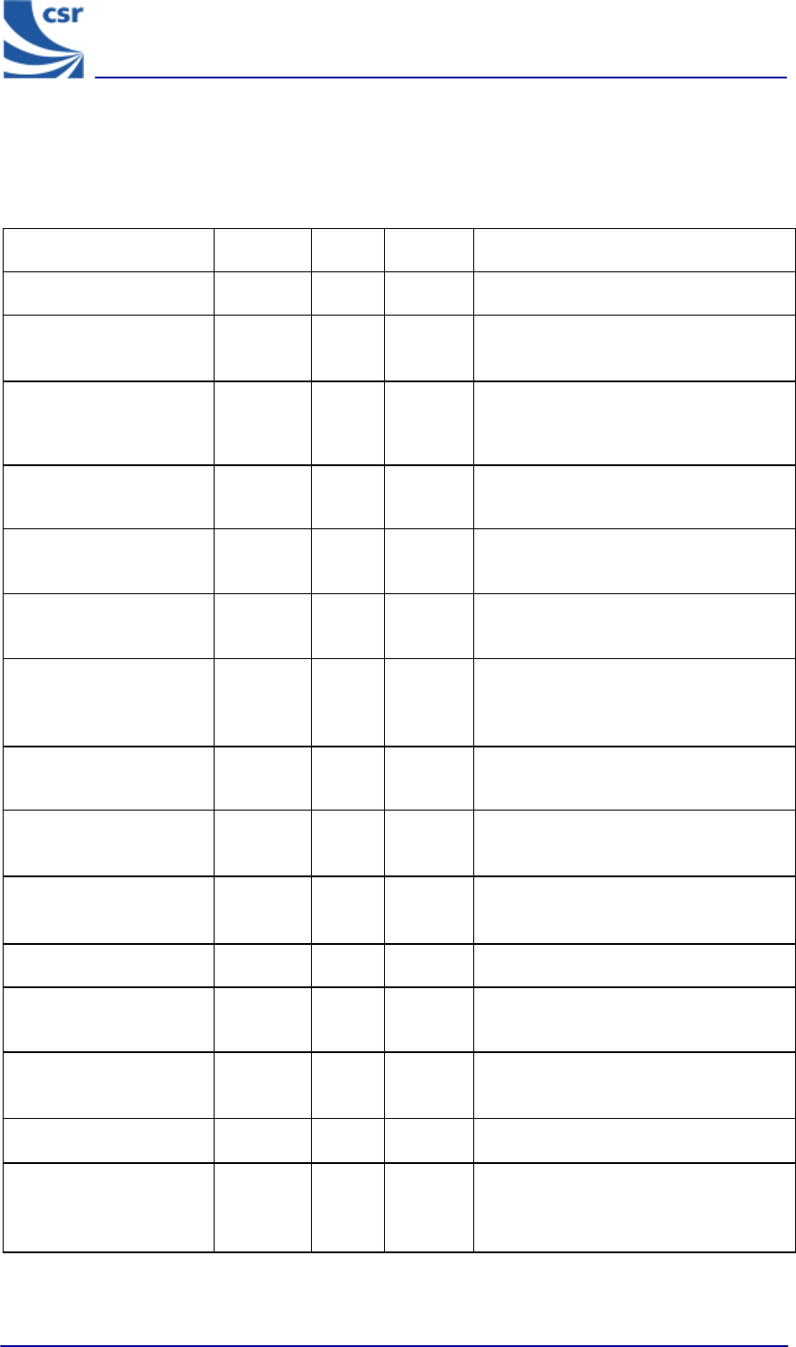
Combining Tests Using a Second Unit
Several tests require a second BlueCore01 unit to be operating to provide a test signal for
the equipment under test. The following table provides a quick reference guide to tests that
use a second unit.
SECOND UNIT
PAUSE
RADIO STATUS
TXSTART
TXDATA1
TXDATA2
TXDATA3
TXDATA4
RXSTART
RXSTART2
RXDATA1
RXDATA2
BIT ERR1
BIT ERR2
LOOP BACK
RX LOOP BACK
BER LOOP BACK
DEEP SLEEP
PCM LB
PCM EXT LB
SETTLE
IF RESP
RF IQ MATCH
IF IQ MATCH
VCO TRIM
BUILD LUT
READ LUT
SET PIO
READ PIO
PROVOKE FAULT
READ CHIP VERSION
EQUIPMENT UNDER
TEST
PAUSE
RADIO STATUS
TXSTART
TXDATA1
TXDATA2
TXDATA3
TXDATA4
RXSTART1
X
RXSTART2
X
RXDATA1
X
RXDATA2
X
BIT ERR1
X
BIT ERR2
X
LOOP BACK
RX LOOP BACK
X
BER LOOP BACK
X
DEEP SLEEP
PCM LB
PCM EXT LB
SETTLE
IF RESP
RF IQ MATCH
IF IQ MATCH
VCO TRIM
BUILD LUT
READ LUT
SET PIO
READ PIO
PROVOKE FAULT
READ CHIP VERSION

BlueTest Instruction Manual
bc01-an-047b
© Copyright CSR 2001
This material is subject to CSR’s non-disclosure agreement.
Page 53 of 56
BlueCore
TM
01
Appendix 4
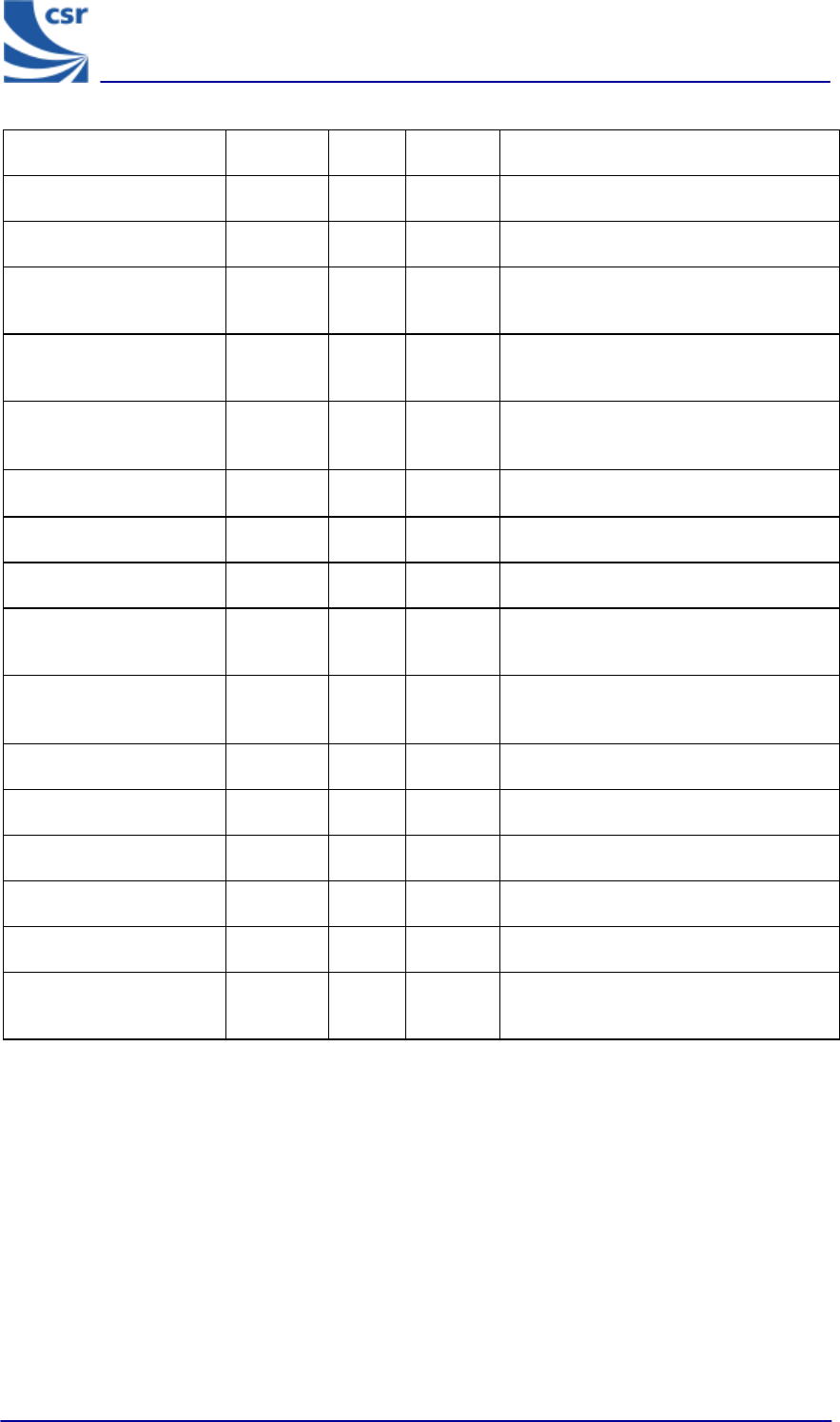
Configuration Commands Available During Tests
Particular configuration commands are appropriate to use during certain tests. The following
table is a quick reference guide to which configuration commands can be used during which
tests.
Configuration
Commands
CFG FREQ
CFG PKT
CFG BIT ERR
CFG TXIF
CFG XTAL FTRIM
CFG UAP/LAP
CFG ACC ERRS
CFG IQ TRIM
CFG TX TRIM
CFG LO LVL
CFG TX COMP
CFG SETTLE
EQUIPMENT
UNDER TEST
PAUSE
RADIO STATUS
TXSTART
X
X
X
TXDATA1
X
X
X
X
X
TXDATA2
X
X
X
X
X
TXDATA3
X
X
X
TXDATA4
X
X
X
RXSTART1
X
RXSTART2
X
RXDATA1
X
RXDATA2
X
BIT ERR1
X
X
X
X
X
BIT ERR2
X
X
X
X
X
LOOP BACK
X
X
RX LOOP BACK
X
X
BER LOOP BACK
X
X
DEEP SLEEP
PCM LB
PCM EXT LB
SETTLE
IF RESP
RF IQ MATCH
IF IQ MATCH
VCO TRIM
BUILD LUT
READ LUT
SET PIO
READ PIO
PROVOKE FAULT
BlueTest Instruction Manual
bc01-an-047b
© Copyright CSR 2001
This material is subject to CSR’s non-disclosure agreement.
Page 54 of 56
BlueCore
TM
01
Appendix 5
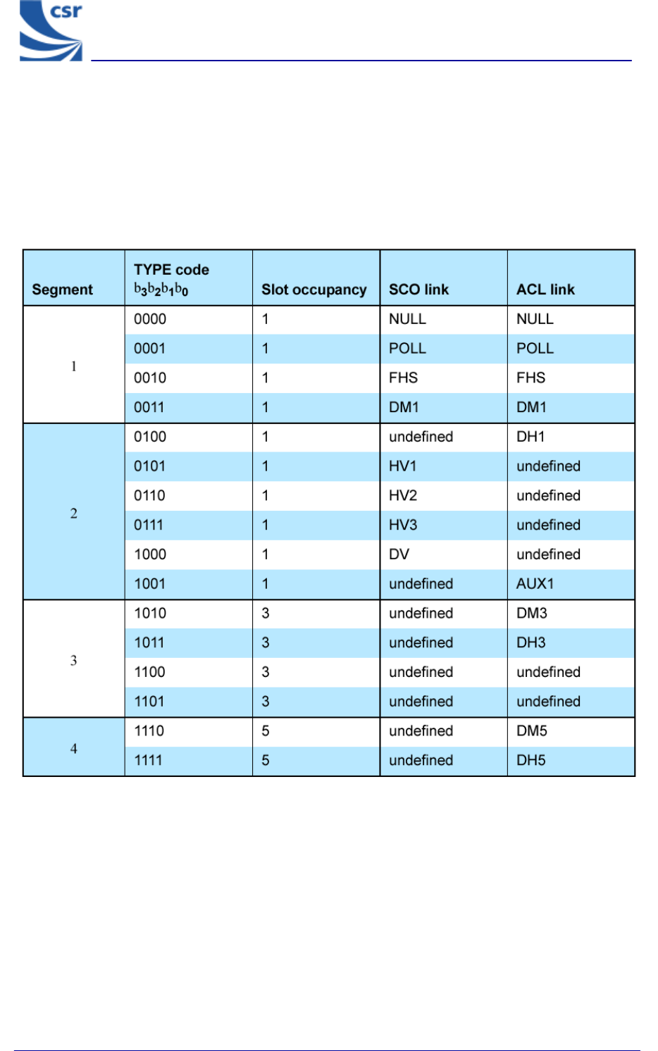
Bluetooth Packet Types
Use the CFG FREQ command to set the frequency as appropriate to the size of the packet type
being used in the test.
Extracted from Packet Types section of Specification of the Bluetooth System, v1.1, dated
1 December 2000.
BlueTest Instruction Manual
bc01-an-047b
© Copyright CSR 2001
This material is subject to CSR’s non-disclosure agreement.
Page 55 of 56
BlueCore
TM
01
CSR’s Life Support Policy and Use in Safety-Critical Applications
CSR’s products are not authorised for use in life-support or safety-critical applications.
Trademarks and Patents
BlueCore is a trademark of CSR.
Bluetooth and the Bluetooth logos are trademarks owned by Bluetooth SIG Inc, USA and
licensed to CSR.
CSR reserves the right to make technical changes to its products as part of its development
programme.
For further information, refer to the following document(s):
Document Reference
Bluetooth (SIG) Test Specification - RF Rev 0.9r, dated 31 January 2000
Specification of the Bluetooth System, v1.1 Rev 1.1, dated 01 December 2000

BlueTest Instruction Manual
bc01-an-047b
© Copyright CSR 2001
This material is subject to CSR’s non-disclosure agreement.
Page 56 of 56
BlueCore
TM
01
Record of Changes
Date: Revision: Reason for Change:
13 SEP 00 a Original publication of this document
(CSR reference: bc01-an-047a).
16 JUL 01 b Revision and addition of tests and appendices
BlueTest Instruction Manual
AN047
July 2001
Federal Communication Commission Interference Statement
This equipment has been tested and found to comply with the limits for a Class B digital
device, pursuant to Part 15 of the FCC Rules. These limits are designed to provide
reasonable protection against harmful interference in a residential installation. This
equipment generates, uses and can radiate radio frequency energy and, if not installed
and used in accordance with the instructions, may cause harmful interference to radio
communications. However, there is no guarantee that interference will not occur in a
particular installation. If this equipment does cause harmful interference to radio or
television reception, which can be determined by turning the equipment off and on, the
user is encouraged to try to correct the interference by one of the following measures:
- Reorient or relocate the receiving antenna.
- Increase the separation between the equipment and receiver.
- Connect the equipment into an outlet on a circuit different from that
to which the receiver is connected.
- Consult the dealer or an experienced radio/TV technician for help.
FCC Caution: Any changes or modifications not expressly approved by the party
responsible for compliance could void the user's authority to operate this equipment.
This device complies with Part 15 of the FCC Rules. Operation is subject to the following
two conditions: (1) this device may not cause harmful interference, and (2) this device
must accept any interference received, including interference that may cause undesired
operation.
IMPORTANT NOTE:
FCC Radiation Exposure Statement:
This equipment complies with FCC radiation exposure limits set forth for an uncontrolled
environment. End users must follow the specific operating instructions for satisfying RF
exposure compliance. To maintain compliance with FCC RF exposure compliance
requirements, please follow operation instruction as documented in this manual.
This transmitter must not be co-located or operating in conjunction with any other antenna
or transmitter.

This device is intended only for OEM integrators under the following conditions:
1) The transmitter module may not be co-located with any other transmitter or antenna,
As long as 1 condition above are met, further transmitter test will not be required. However,
the OEM integrator is still responsible for testing their end-product for any additional
compliance requirements required with this module installed (for example, digital device
emissions, PC peripheral requirements, etc.).
IMPORTANT NOTE: In the event that these conditions can not be met (for example
certain laptop configurations or co-location with another transmitter), then the FCC
authorization is no longer considered valid and the FCC ID can not be used on the final
product. In these circumstances, the OEM integrator will be responsible for re-evaluating
the end product (including the transmitter) and obtaining a separate FCC authorization.
End Product Labeling
The final end product must be labeled in a visible area with the following: “Contains FCC
ID: O9NPB”.
Manual Information To the End User
The OEM integrator has to be aware not to provide information to the end user regarding
how to install or remove this RF module in the user’s manual of the end product which
integrates this module.
The end user manual shall include all required regulatory information/warning as show in
this manual.
Canadian Regulatory Wireless Notice
This device complies with RSS-210 of the Industry Canada Rules. Operation is subject to
the following two conditions:
1) this device may not cause interference and
2) this device must accept any interference, including interference that may cause
undesired operation of the device
IMPORTANT NOTE:
IC Radiation Exposure Statement:
This equipment complies with IC radiation exposure limits set forth for an uncontrolled
environment. End users must follow the specific operating instructions for satisfying RF
exposure compliance. To maintain compliance with IC RF exposure compliance
requirements, please follow operation instruction as documented in this manual.