Datalogic ADC RSW802BT Falcon 4410, 4420 User Manual
Datalogic ADC, Inc. Falcon 4410, 4420
Contents
- 1. User Manual 2
- 2. User Manual 1
User Manual 1

Quick Reference Guide
Falcon
®
4400 Series
with Windows
®
CE
Falcon 4410
26-Key model
Falcon 4420
48-Key model Falcon 4410
52-Key NU model
PSC Inc
959 Terry Street
Eugene, Oregon 97402
Telephone: (541) 683-5700
Fax: (541) 345-7140
An Unpublished Work - All rights reserved. No part of the contents of this documentation or the procedures
described therein may be reproduced or transmitted in any form or by any means without prior written permission of
PSC Inc. or its wholly owned subsidiaries ("PSC"). Owners of PSC products are hereby granted a non-exclusive,
revocable license to reproduce and transmit this documentation for the purchaser's own internal business pur-
poses. Purchaser shall not remove or alter any proprietary notices, including copyright notices, contained in this
documentation and shall ensure that all notices appear on any reproductions of the documentation.
Should future revisions of this manual be published, you can acquire printed versions by contacting your PSC rep-
resentative. Electronic versions may either be downloadable from the PSC website (www.psc.com) or provided on
appropriate media. If you visit our website and would like to make comments or suggestions about this or other
PSC publications, please let us know via the “Contact PSC” page.
Disclaimer
PSC has taken reasonable measures to provide information in this manual that is complete and accurate, however,
PSC reserves the right to change any specification at any time without prior notice.
PSC is a registered trademark of PSC Inc. The PSC logo is a trademark of PSC. All other trademarks and trade
names referred to herein are property of their respective owners.
Falcon® is a registered trademark of PSC Inc. and of its wholly owned subsidiaries.
Microsoft Windows®, Windows® 2000, Windows®CE, Windows® NT, and Windows® XP are registered trademarks of
Microsoft Corporation.
Patents
This product may be covered by one or more of the following patents: 4603262 • 4639606 • 4652750 • 4672215 • 4699447 • 4709369 •
4749879 4786798 • 4792666 • 4794240 • 4798943 • 4799164 • 4820911 • 4845349 • 4861972 • 4861973 • 4866257 • 4868836 •
4879456 • 4939355 • 4939356 • 4943127 • 4963719 • 4971176 • 4971177 • 4991692 • 5001406 • 5015831 • 5019697 • 5019698 •
5086879 • 5115120 • 5144118 • 5146463 • 5179270 • 5198649 • 5200597 • 5202784 • 5208449 • 5210397 • 5212371 • 5212372 •
5214270 • 5229590 • 5231293 • 5232185 • 5233169 • 5235168 • 5237161 • 5237162 • 5239165 • 5247161 • 5256864 • 5258604 •
5258699 • 5260554 • 5274219 • 5296689 • 5298728 • 5311000 • 5327451 • 5329103 • 5330370 • 5347113 • 5347121 • 5371361 •
5382783 • 5386105 • 5389917 • 5410108 • 5420410 • 5422472 • 5426507 • 5438187 • 5440110 • 5440111 • 5446271 • 5446749 •
5448050 • 5463211 • 5475206 • 5475207 • 5479011 • 5481098 • 5491328 • 5493108 • 5504350 • 5508505 • 5512740 • 5541397 •
5552593 • 5557095 • 5563402 • 5565668 • 5576531 • 5581707 • 5594231 • 5594441 • 5598070 • 5602376 • 5608201 • 5608399 •
5612529 • 5629510 • 5635699 • 5641958 • 5646391 • 5661435 • 5664231 • 5666045 • 5671374 • 5675138 • 5682028 • 5686716 •
5696370 • 5703347 • 5705802 • 5714750 • 5717194 • 5723852 • 5750976 • 5767502 • 5770847 • 5786581 • 5786585 • 5787103 •
5789732 • 5796222 • 5804809 • 5814803 • 5814804 • 5821721 • 5822343 • 5825009 • 5834708 • 5834750 • 5837983 • 5837988 •
5852286 • 5864129 • 5869827 • 5874722 • 5883370 • 5905249 • 5907147 • 5923023 • 5925868 • 5929421 • 5945670 • 5959284 •
5962838 • 5979769 • 6000619 • 6006991 • 6012639 • 6016135 • 6024284 • 6041374 • 6042012 • 6045044 • 6047889 • 6047894 •
6056198 • 6065676 • 6069696 • 6073849 • 6073851 • 6094288 • 6112993 • 6129279 • 6129282 • 6134039 • 6142376 • 6152368 •
6152372 • 6155488 • 6166375 • 6169614 • 6173894 • 6176429 • 6188500 • 6189784 • 6213397 • 6223986 • 6230975 • 6230976 •
6237852 • 6244510 • 6259545 • 6260763 • 6266175 • 6273336 • 6276605 • 6279829 • 6290134 • 6290135 • 6293467 • 6303927 •
6311895 • 6318634 • 6328216 • 6332576 • 6332577 • 6343741 • 6454168 • 6478224 • 6568598 • 6578765 • 6705527 • 6974084 •
6991169 •7051940 • AU703547 • D312631 • D313590 • D320011 • D320012 • D323492 • D330707 • D330708 • D349109 • D350127 •
D350735 • D351149 • D351150 • D352936 • D352937 • D352938 • D352939 • D358588 • D361565 • D372234 • D374630 • D374869 •
D375493 • D376357 • D377345 • D377346 • D377347 • D377348 • D388075 • D446524 • EP0256296 • EP0260155 • EP0260156 •
EP0295936 • EP0325469 • EP0349770 • EP0368254 • EP0442215 • EP0498366 • EP0531645 • EP0663643 • EP0698251 •
GB2252333 • GB2284086 • GB2301691 • GB2304954 • GB2307093 • GB2308267 • GB2308678 • GB2319103 • GB2333163 •
GB2343079 • GB2344486 • GB2345568 • GB2354340 • ISR107546 • ISR118507 • ISR118508 • JP1962823 • JP1971216 • JP2513442
• JP2732459 • JP2829331 • JP2953593 • JP2964278 • MEX185552 • MEX187245 • RE37166 • Other Patents Pending

Quick Reference Guide 1
Table of Contents
Falcon® 4400 Serieswith Windows® CE .............................................................. 3
Overview ......................................................................................................................3
Getting Started ..............................................................................................................4
Features of the Falcon ...................................................................................................4
Powering the Falcon .......................................................................................................8
Getting Started ..............................................................................................................8
Battery Pack ...........................................................................................................8
Installing the Battery Pack .......................................................................................9
Checking Battery Power .......................................................................................... 11
System Tray Battery Status Indicators ...................................................................... 11
Charging the Batteries ............................................................................................ 12
Charging with a Battery Charger .............................................................................. 13
Charging with the Dock ........................................................................................... 13
Backup Battery ...................................................................................................... 14
Battery Discharge Characteristics ............................................................................ 14
Setting Up the Mobile Computer ..................................................................................... 15
Touchscreen Calibration .......................................................................................... 15
Getting Connected ................................................................................................. 15
Setting the Date and Time ...................................................................................... 17
Entering Data .............................................................................................................. 18
Using the Stylus .................................................................................................... 18
Navigating the Display ............................................................................................ 19
Keypads ............................................................................................................... 22
Scanning Bar Codes ..................................................................................................... 29
Laser Scanning ...................................................................................................... 29
Bar Code Scanning with 2D Imager .......................................................................... 31
Image Capture ............................................................................................................ 32
Flash Memory .............................................................................................................. 33
Saving to Flash ...................................................................................................... 33
Flash FX Location ................................................................................................... 33
FlashFX Disk Size ................................................................................................... 34
Context Sensitive Help .................................................................................................. 35
Resetting the Falcon ..................................................................................................... 36
Warm Reset .......................................................................................................... 36
Cold Reset ............................................................................................................ 37
Maintaining the Falcon .................................................................................................. 39

Quick Reference Guide 2
Troubleshooting ........................................................................................................... 40
RF Connectivity Troubleshooting .............................................................................. 43
Technical Support ........................................................................................................ 44
PSC Website Support .............................................................................................. 44
PSC Website TekForum ........................................................................................... 44
Reseller Technical Support ...................................................................................... 44
Telephone Technical Support ................................................................................... 44
Appendix A: PSC Falcon
®
Windows
®
CE Series
End User License Agreement........................................................................ 45
Appendix B: Microsoft
®
Windows
®
CE
End User License Agreement ........................................................................48
Appendix C: PSC Falcon
®
Windows
®
CE Product Series Warranty ...................... 49
Appendix D: Safety Information ........................................................................50
Laser Safety Label ........................................................................................................ 50
Advisory Statement ................................................................................................ 50
Regulatory Statements ................................................................................................. 50
Radio Frequency Interference .................................................................................. 50
Canadian Compliance Statement .............................................................................. 50
Appendix E: Laser Safety ...................................................................................51
International Caution Statements for CLASS 1, 2, 3R, II, and IIA Laser Devices ................... 51
English ................................................................................................................. 51
French .................................................................................................................. 51
German ................................................................................................................ 52
Italian .................................................................................................................. 52
Danish .................................................................................................................. 53
Dutch ................................................................................................................... 53
Swedish ................................................................................................................ 53
Finnish ................................................................................................................. 54
Norwegian ............................................................................................................ 54
Portuguese ........................................................................................................... 55
Spanish ................................................................................................................ 55
Chinese ................................................................................................................ 56
Japanese .............................................................................................................. 57

Quick Reference Guide 3
Falcon
®
4400 Series
with Windows
®
CE
Overview
The Falcon® 4400 combines the flexibility of Windows® CE with the power
of the Intel XScale processor, WiFi wireless technology, a large color display,
laser (1D) and imaging (1D and 2D) scanning in an ergonomic PDT. The Fal-
con® 4400 series is designed for warehouses, distribution centers, retail in-
store environments, and other inventory management applications requiring
maximum performance and durability.
New options available for the Falcon 4400 include 128/128 memory, a full
alphanumeric Numbers Up Keypad, and a high-density 2D scan engine.
Overmolded models will handle 5’ / 1.5M drops to concrete, and have an
IP54 environmental rating; and an 86dBA (at 24") / 100dBA (at 10 cm)
beeper. The Falcon® 4400 will handle demanding data collection tasks in
industrial environments.
The Falcon Management Utility (FMU) and Falcon Desktop Utility (FDU)
are included with every unit, providing remote management and configurabil-
ity.
This Quick Reference Guide contains the following sections:
• Features of the Falcon on page 4 — describes the functions and keys of
the Falcon.
• Powering the Falcon on page 8 — gives information about the batteries,
shows how to install the battery pack, and provides options for charging.
• Setting Up the Mobile Computer on page 15 — tells how to calibrate
the Touchscreen, set up the radio cards, and set up other options.
• Entering Data on page 18 — using the stylus, navigating the display,
about keypads, and bar code scanning.
•Flash Memory on page33 — about the Flash FX disk.
• Context Sensitive Help on page 35 — accessing Help from the Falcon.
• Resetting the Falcon on page 36 — describes warm and cold resets.
• Troubleshooting and PSC Technical Support starting on page 40.

Getting Started
4Falcon
® 4400 Series with Windows® CE
Getting Started
Before using the Falcon for the first time, you must install the battery pack
into the Falcon, then charge both the battery pack and the backup battery. See
Installing the Battery Pack on page 9 for instructions.
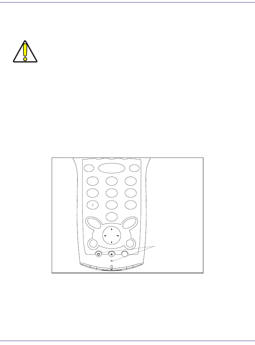
Features of the Falcon
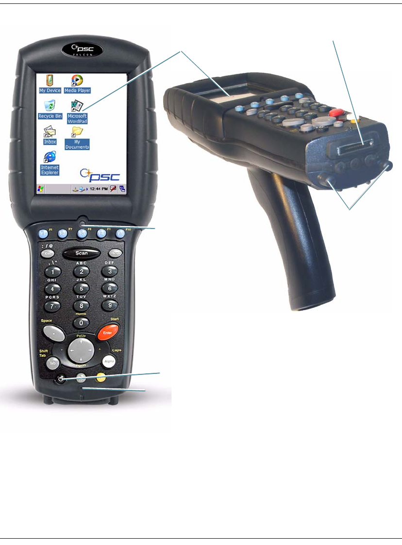
Four perspectives of the Falcon® 4400 mobile computer are shown. Refer to
Table 1 on page 7 for a list of the illustrated parts with references to more
detailed information.
CAUTION
You must charge the battery pack and backup battery in a dock or with a power
cable prior to your first use of the Falcon. The initial charge time is approximately
24 hours. See Charging the Batteries on page 12 for more information.
Features of the Falcon
Quick Reference Guide 5
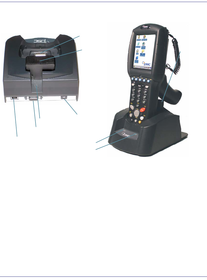
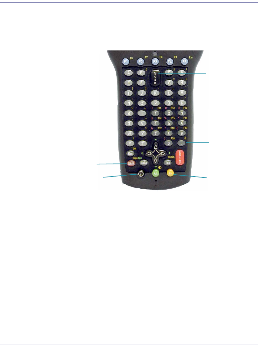
Figure 1. Falcon Front View and Connector View
For a complete description of each key on the Falcon, refer to page 22.
Touchscreen
Display
Handle
Falcon
44xx
26-Key
Keypad
USB/Serial Connector
Strap Studs
w/Rubber
Bumpers
Falcon 4420
Handled model
Reset
Power Key
LED Scanning/
Charging Indicator

Features of the Falcon
6Falcon
® 4400 Series with Windows® CE
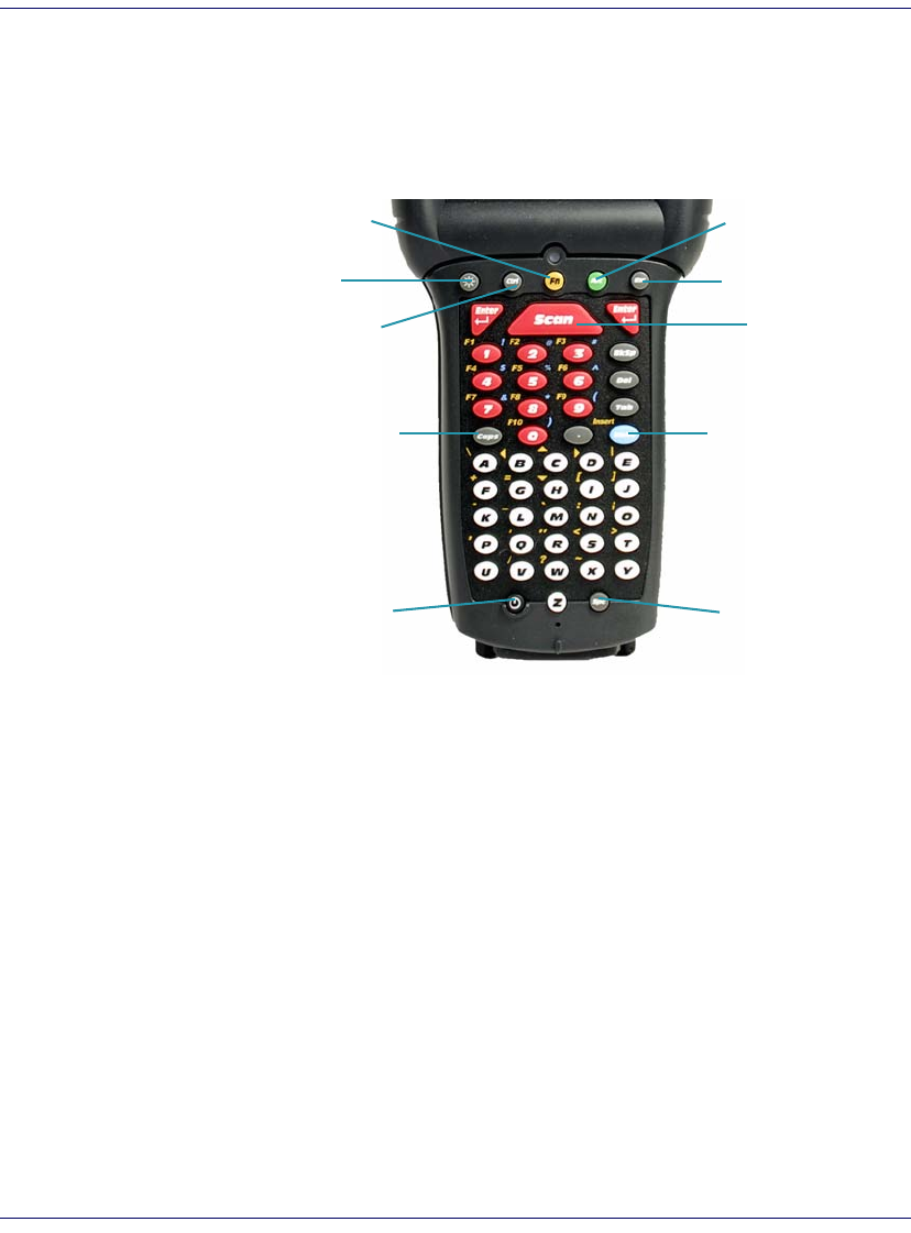
Figure 2. Falcon Scanner and Battery Door Views
For more information, please refer to the Falcon® 4400 Windows® CE Mobile
Computer Product Reference Guide (PRG), located on the Falcon 4400 Product
CD that came with your device.
Strap Studs
Trigger
Handle
Stylus
Tether/Lanyard Port
Stylus Holder
Battery Door
Speaker
Battery Door
Latch
(2 each)
Scanner Aperture
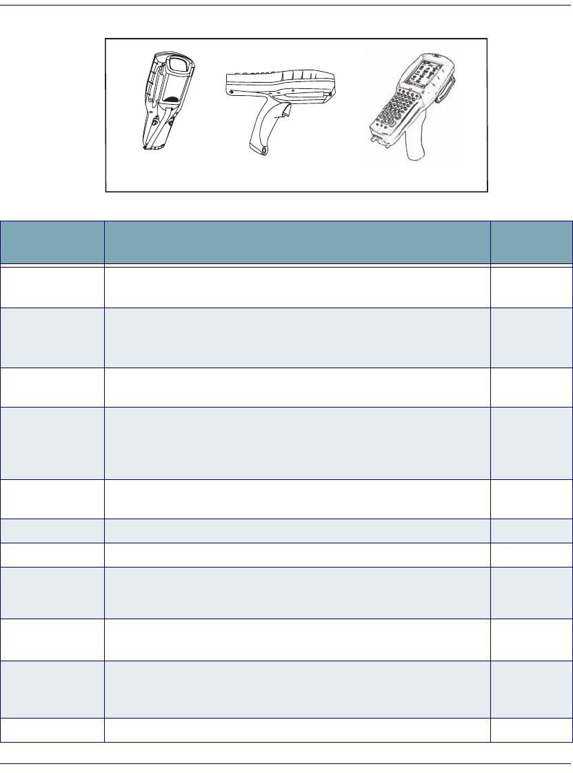
Features of the Falcon
Quick Reference Guide 7
Figure 3. Model comparison
Table 1. Features of the Falcon
Feature Function/Description More
Information
Battery Door Rotate the latches to unlock the battery door so the battery pack can be
removed.
Figure 4,
page 9
Display/Touch
Screen
The equivalent of a PC monitor for viewing and interacting with the current
application. This display is touch-sensitive; use it like you would a mouse on
a PC.
Figure 1,
page 15,
page 20
Handle The Falcon 442X comes with a handle that is ergonomically designed for
ease of use with a scanner trigger. Figure 1
Reset key
Insert an object, such as a paper clip, into this hole to perform a cold reset of
the unit. PSC recommends that you attempt a warm reset first.
Do not use a sharp object, or you could disable the reset function, puncture
the keypad’s industrial seal, and void your warranty.
page 36
Keypad Use the alpha-numeric, function, and navigation keys on the keypad to enter
numbers, letters, symbols and navigate with the keypad. page 22
Lanyard Port Insert a lanyard to secure a Falcon to a person or work station. page 6
Scanner Aperture The laser or imaging scanning beam is emitted from this aperture. page 29
LED
When scanning, a red LED indicates the laser is on and a green LED indicates a
good read. When the Falcon is charging in the dock, a red LED on the Falcon indi-
cates charging and a green LED on the Falcon indicates fully charged.
Figure 1
Power Key Press the Power key to turn the Falcon on and off, or to toggle the device
between suspend (sleep) mode and resume (on).
Figure 1,
page 23
Speaker
The speaker plays *.WAV and other media files, emits beeps or tones to
indicate errors or good reads when bar code scanning and inputting data
using the keypad or stylus.
Figure 2
Strap Studs The Falcon 441X comes with a handstrap that connects to the strap studs. Figure 2
Model 4420
Model 4410 Model 4420 with Tethered Stylus
Powering the Falcon
8Falcon
® 4400 Series with Windows® CE
Powering the Falcon
Getting Started
Before using the Falcon for the first time, you must install the battery pack
into the Falcon, then charge both the battery pack and the backup battery. See
Installing the Battery Pack on page 9 for instructions.
Battery Pack
The battery pack in the Falcon is a 3.7 V, 2000
mAh Lithium Ion battery pack. You will be
alerted with a message dialog box when the bat-
tery pack reaches a low state.
After charging the first time, a complete charge
takes about four (4) hours depending on the bat-
Stylus
Use the stylus for navigation, the soft input panel (SIP), and to select items
on the touch screen. Place the stylus in the holder after use so you don’t lose
or misplace it. An optional Stylus Tether is available for all models.
Figure 10,
page 18
Feature Function/Description More
Information
CAUTION
You must charge the battery pack and backup battery in a dock or with a power
cable prior to your first use of the Falcon. The initial charge time is approximately
24 hours. See Charging the Batteries on page 12 for more information.
3.7V
Li-ion
CAUTION: Battery can explode, leak or catch
fire if exposed to high temperature, water or fire.
Do not short circuit, open or disassemble battery.
Recycle or dispose of properly.
2000mAh
5-1764
Product of USA
U S
Getting Started
Quick Reference Guide 9
tery pack’s state and the recharging method. A sample battery pack label is
shown at the right.
Installing the Battery Pack
When you first remove the Falcon from the box, you must charge both the
battery pack and the backup battery for a minimum of 24 hours.
Complete the following instructions to install the battery pack:
CAUTION
You must charge the battery pack and backup battery in a dock or with a power
cable prior to your first use of the Falcon. The initial charge time is approximately
24 hours.
If you remove the battery pack or it fails, there is a 30 minute window in which to
insert a charged battery pack before the backup battery fails. If your backup bat-
tery fails, the contents of the RAM memory will be lost. If your back-up battery is
less than fully charged, there is a proportionally smaller window of time available.
Usage time will be reduced, also.
Always charge the battery pack within the temperature range of 32°–113°F (0°–
45°C).
Use only the authorized power supplies, battery packs, chargers, and docks sup-
plied by your PSC reseller. The use of an other power supplies can damage the
Falcon and void your warranty. Refer to the PRG for the correct power supplies
and Accessories.
WARNING
Lithium-ion battery packs may get hot, explode, ignite, or/and cause serious injury if
exposed to abusive conditions.
• Do not place the battery in or near fire, direct sunlight, or other high tempera-
ture locations, or heat the battery.
• Do not install the battery backwards so the polarity is reversed.
• Do not connect the positive terminal and negative terminal of the battery to
each other with any metal object (such as wire or coin).
• Do not expose the battery to liquids, or allow the battery to get wet.
• Do not disassemble, modify, or pierce the battery. The battery contains safety
and protection devices, which, if damaged, may cause the battery to generate
heat, explode or ignite.
In the event the battery leaks and the fluid gets into your eye, do not rub the eye.
Rinse well with water and immediately seek medical care. If left untreated, the battery
fluid could cause damage to the eye.
PSC recommends annual replacement of rechargeable battery packs to ensure
maximum performance.
Getting Started
10 Falcon® 4400 Series with Windows® CE
1. On a 441X, detach the elastic handstrap by releasing its hook from
the strap studs at the base of the unit (refer to the PRG).
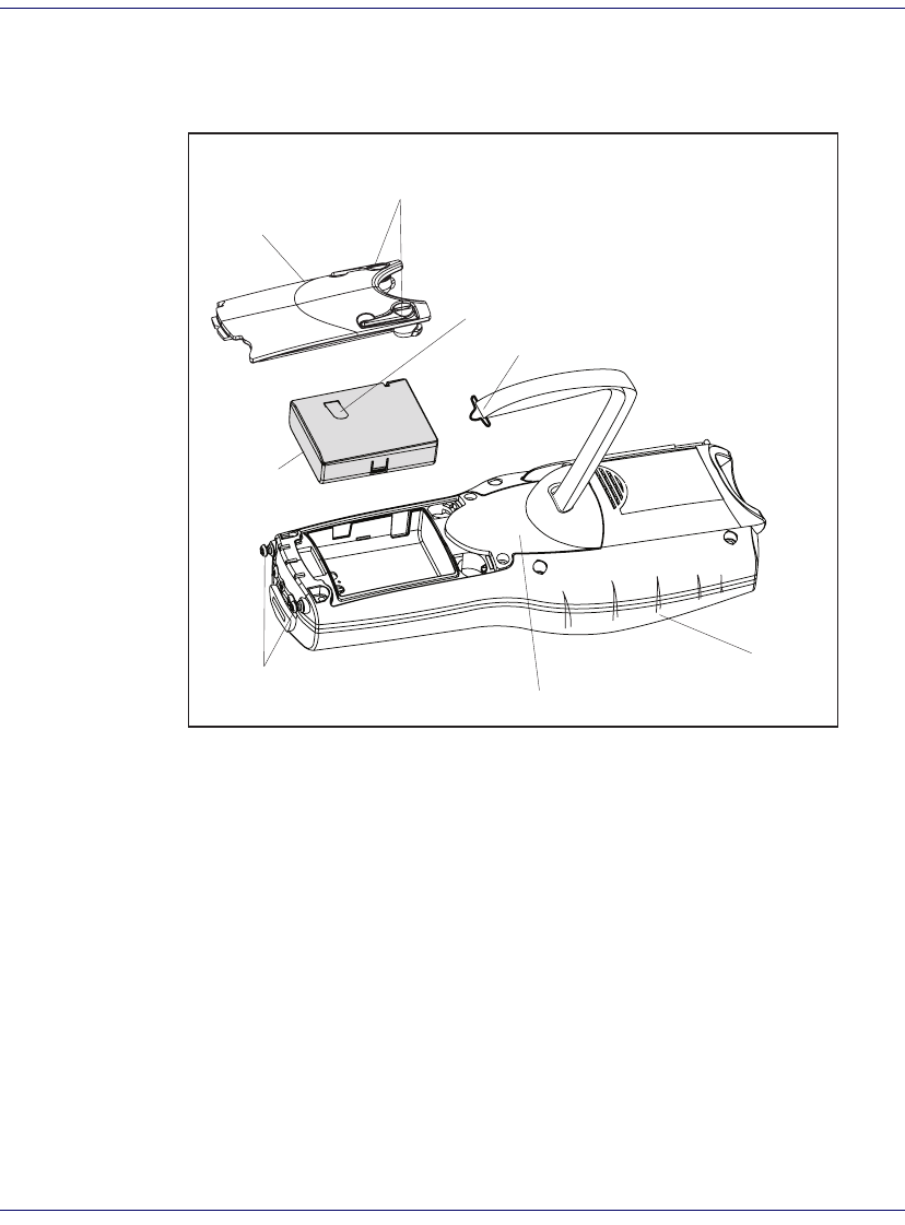
Figure 4. Installing the Battery Pack
2. Turn the battery door latches to unlock the battery door. Remove the
door.
3. Insert the battery pack with the pull tab on the outside and the bat-
tery contacts aligned with the matching contacts inside the battery
compartment. The battery pack has a keying feature on one side to
prevent incorrect installation (refer to Figure 4).
4. Replace the battery door by inserting the bottom tab into the slot. If
the battery pack is installed incorrectly, the door will not seat properly.
5. Rotate the battery door latches on the battery compartment cover
towards the base of the unit.
6. On the 441X, replace the handstrap hook on the strap stud at the base
of the unit.
Battery Door
Cover Plate (unit may have Handle here instead)
Falcon
Battery Door Latches
Unhook/hook Strap As Needed
Battery
Plastic Pull Tab
Strap Studs
Getting Started
Quick Reference Guide 11
Checking Battery Power
If you remove the battery pack or the battery fails, you have about 30 minutes
to swap in a new battery pack or charge the battery pack before the backup
battery fails (if the backup battery has been fully charged).
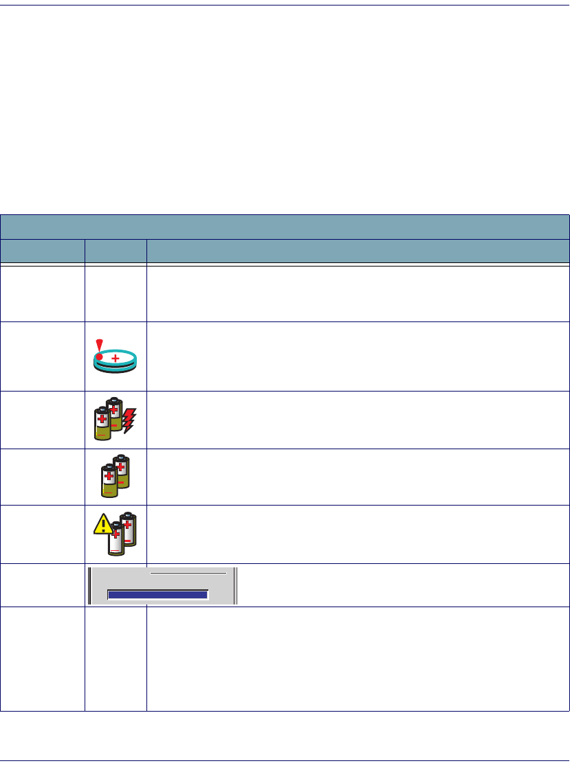
System Tray Battery Status Indicators
The System Tray displays icons to show the status of some battery conditions,
as shown in Table 2.
Table 2. System Tray Battery Status Indicators
Battery Status Icons
Battery Status Icon Description
Backup
Battery Low
Condition
no icon The battery status is updated in the control panel, but no icon is displayed.
Backup
Battery Very
Low Condition
When the backup battery is very low, the system tray contains a very low backup
battery CAUTION icon. In addition, a dialog box pops up and alerts you that the
backup battery is very low and needs to be charged. The dialog comes up every five
minutes until you charge the backup battery.
Battery
Charging
Condition
This icon indicates that the battery pack is currently charging.
Battery Low
Condition This icon indicates that the battery pack is low.
Battery Very
Low Condition
When the battery pack is very low, the system tray shows a very low battery CAU-
TION icon. Also, a dialog box pops up and alerts you to charge the battery pack. A
battery warning dialog will pop up every five minutes until you charge the battery.
Battery Power
Gauge
The Power control applet displays a battery power gauge.
Start > Settings > Control Panel > Power.
Discharged
Battery
Condition no icon
When the battery is totally discharged, the battery sensor initiates a shutdown of all
applications, and closes the RF Network connection. If the battery pack has com-
pletely discharged, when the battery pack is charged or replaced, the unit will
resume as before after a cold reset.
Refer to Flash Memory on page 33 regarding the data loss of applications and data
stored in RAM.
Main batteries
Remaining power:
0 100
Getting Started
12 Falcon® 4400 Series with Windows® CE
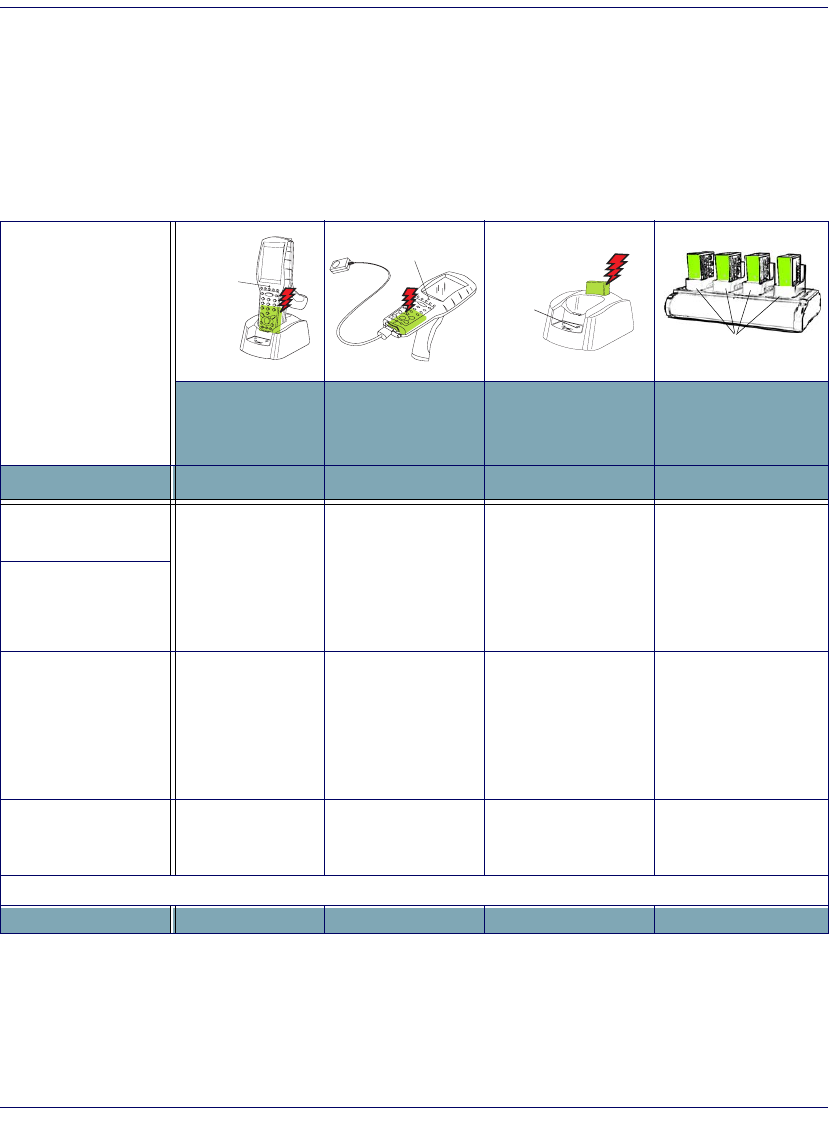
Charging the Batteries
There are several methods for charging the battery pack and backup battery.
LEDs on the Falcon, the Single-Slot Dock, Four-Slot Dock, and Four-Slot
Battery charger give visual indication of the charge state. Table 3 gives an over-
view of all the LEDs and what they indicate.
Table 3. Battery Charging Methods and Indications
Charging Location:
Falcon seated in a
Dock (Single or
Four-Slot)
Falcon connected
to an external
power supply
Charging slot of
Dock (Single or
Four-Slot)
Four-Slot Battery
Charger
Charging Duration 4-6 hours 4-6 hours 3-5 hours > 3 hours
Battery Pack Charge
Indication: Charging: RED
Fully Charged:
GREEN
Charging: RED
Fully Charged:
GREEN
N/A N/A
Falcon Charge LED
Dock or Charger
Battery Charge
LED(s)
No effect No effect
Charging:
Solid RED
Fully charged:
GREEN
*Fault:
Flashing RED
Charging:
LEDs are AMBER
Fully charged:
LEDs are GREEN
Simultaneously
Charges
Backup Battery?
YES YES NO NO
* Refer to page 43 for more information.
PDT
Charge
LED
PDT Charge LED
Spare
Battery
Charge
LED
Charge Indicator LEDs
Getting Started
Quick Reference Guide 13
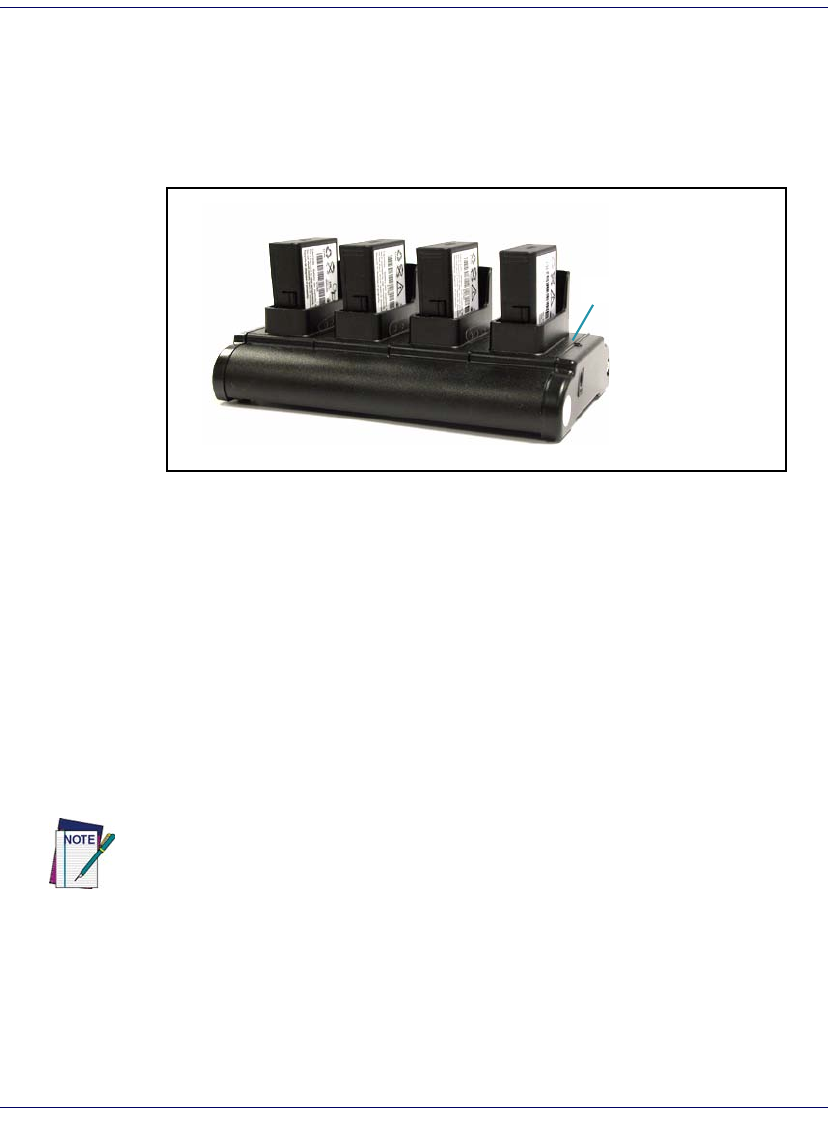
Charging with a Battery Charger
A LiIon Four-Slot Battery Charger is available to charge batteries indepen-
dently from the Falcon. To use, align the battery contacts with those in the
Charger and insert them into the slots.
Figure 5. Four-Slot Battery Charger
Charging with the Dock
There are two models of docks for the Falcon: a Single-Slot Dock and a Four-
Slot Dock. On both models, an external power supply (AC adaptor) provides
power to the dock. Falcons communicate with the host PC using Microsoft
ActiveSync protocol either via a USB port or via a serial port.
There are two methods for charging a battery pack using a Single-Slot Dock.
Refer to Table 3 on page 12 to view methods of battery pack charging using
the dock, charge duration, dock status indicators and their purpose. For more
information on the dock, refer to the Dock Operating Instructions that come
with each dock.
Power Indicator LED
Use only the correct battery chargers and docks with this Windows CE color Fal-
con. This technology used for these models is incompatible with other PSC Fal-
con chargers and docks, including the Falcon 4410/4420 monochrome models.
Getting Started
14 Falcon® 4400 Series with Windows® CE
Figure 6. Charging the Battery Pack in a Single-Slot Dock
Refer to Table 3 on page 12 for a list of LED indicators and their purpose.
Refer to the PRG for additional information on storage and disposal of batter-
ies.
Backup Battery
The 3V Lithium Backup Battery receives its charge from the Battery Pack. To
retain date, time, data, and other settings for the Falcon, maintain at least a
minimal charge on the Battery Pack.
When the backup battery is low, an icon will display on the status bar (see
Table 2 on page 11), and a dialog box will open to alert you.
Battery Discharge Characteristics
Battery discharge characteristics vary from eight to nine and a half (8-9.5)
hours, depending upon device usage, number of scans per minute, backlight
usage, and other factors that draw upon battery power.
Spare Battery LED
Power LED
Power Port
RS-232 Serial Port
USB Port
Battery Tab
USB/Serial Connector
Battery Pack in
Spare Battery
Charging Slot
Top/Rear View of Single-Slot Dock
Battery Pack in
Spare Battery
Charging Slot
Setting Up the Mobile Computer
Quick Reference Guide 15
Setting Up the Mobile Computer
At first use or after a cold reset, the unit will go through a series of initial
bootup sequences. Each of these sequences are described as noted:
1. Touchscreen Calibration, illustrated in Figure 7.
2. Radio Card Setup on page 15.
3. Installing the USB Driver on page 16.
4. Network Setup on page 16.
5. Setting the Date and Time on page 17.
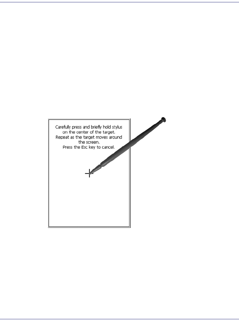
Touchscreen Calibration
Figure 7. Touchscreen Calibration
Getting Connected
Radio Card Setup
For assistance in configuring a radio card, tap the question mark on your Fal-
con to access the Microsoft online help. Windows Zero Config should be used
to administer the radio for cards not specifically listed (for example, DRCB or
Broadcom based radio). Refer to the manufacturer of your radio card for fur-
Follow the on-screen directions to cali-
brate the touchscreen.
For more information on touchscreen
calibration, refer to the PRG.

Setting Up the Mobile Computer
16 Falcon® 4400 Series with Windows® CE
ther information. If you have a Cisco card go to www.cisco.com; for Symbol
go to www.symbol.com.
Installing the USB Driver
So the Host PC can communicate with the Falcon, install the USB driver file
from the CD that came with the Falcon, or download it from the PSC website.
Follow the directions on the CD, or use the following instructions:
1. Microsoft® ActiveSync must be installed on your computer before pro-
ceeding. Go to www.microsoft.com for information.
2. Copy the current USB driver file from the Falcon CD to the C:\Pro-
gram Files\Microsoft ActiveSync\Drivers.
3. Connect the USB cable to the Falcon or place the Falcon in the dock.
4. Connect the USB cable to the Host PC.
5. Follow directions on screen. The specified source directory is the one
identified in step 2.
Serial Cable Setup
1. To connect the Falcon using a Serial cable, go to Start > Settings > Control
Panel > PC Connection.
2. If not already checked, select Enable direct connections to the desktop com-
puter.
3. Tap Change Connection and select Serial from the dropdown box.
4. Tap OK.
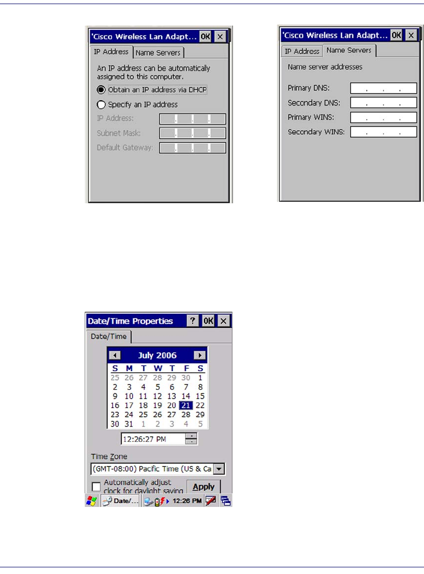
Network Setup
To set up the Network connection settings, complete the following steps:
1. Select Start > Settings > Network and Dialup Connections.
2. Double-tap on the wireless card icon (varies based upon the radio
installed and the number of connections).
3. Complete the two tabs (shown in Figure 8):
Setting Up the Mobile Computer
Quick Reference Guide 17
Figure 8. Modifying the Network Connection Settings.
•IP Address: Select DHCP or set static IP settings.
•Name Servers: If using static IP, set DNS and WINS servers.
Setting the Date and Time
To set or change the date and time, complete the following steps:
Figure 9. Setting the Date and Time
1. From the Start menu, select Settings >
Control Panel > Date/Time to open the
Date/Time Properties control panel.
Use the arrows in the application to
navigate, increase or decrease the
time or date.
2. Select the year to open a field where
you can change the year by backspac-
ing, or entering a new year.
3. Select the month to open a pull-
down list of months.
4. Tap the checkbox to Automatically
adjust clock for daylight savings time, if
desired.

Entering Data
18 Falcon® 4400 Series with Windows® CE
Entering Data
To open applications, select Start > Programs to display a list of available pro-
grams. If the program has an icon on the desktop, double-tap to open it.
There are several ways to enter data with the Falcon:
• Use the keypad. Refer to Keypads starting on page 22.
• Use the stylus on the touchscreen display. Refer to Using the Stylus on
page 18 for more information on using the stylus.
• Use the soft input panel (digital keyboard) with the stylus. Refer to
Soft Keypad/Input Panel on page 21.
• Select text in the same way you select text on a PC. Use the stylus to
highlight the desired text by dragging the stylus across the desired
text, double-tapping to select one word, and triple-tapping to select
an entire line.
• Use the bar code scanner to enter data. Press the trigger or scan button
to initiate a scan. The scanned data will be entered into the current
application’s open file. Refer to Scanning Bar Codes starting on
page 29 for more information on using the scanner.
• If your Falcon has the 2D Imaging module installed, you can read and
decode traditional 1D linear bar codes, 2D and composite symbols.
You can also capture images such as signatures, labels, and other items.
See Bar Code Scanning with 2D Imager starting on page 31 for fur-
ther information.
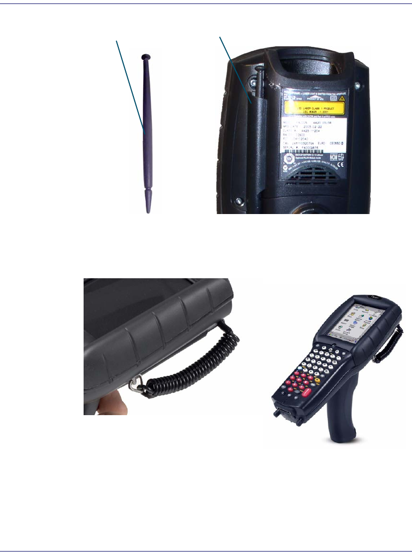
Using the Stylus
The stylus is located next to the scanning pod as illustrated in Figure 10. The
stylus on the Falcon is the equivalent of the mouse on a PC. Use the stylus to:
• Navigate the touchscreen display.
• Select characters in the soft input panel (SIP).
• Select applications from the desktop or system tray.
• Select tabs, fields and text within applications and dialog boxes.
Never use a pen, pencil, or other sharp object on the Falcon’s touchscreen dis-
play. Use only the supplied stylus or plastic-tipped pens intended for use with a
touch-sensitive display. Contact your reseller to replace a missing stylus; refer to
the PSC price book at www.psc.com.
Entering Data
Quick Reference Guide 19
Figure 10. Back View of a Falcon 4420 with a Stylus
It is good practice to replace the stylus into the holder after each use so you
don’t misplace it. An optional Tethered Stylus is also available, preventing acci-
dental loss of the stylus.
Figure 11. Tethered Stylus
Stylus Stylus Holder
Tethered Stylus
Entering Data
20 Falcon® 4400 Series with Windows® CE
Navigating the Display
There are several navigation areas on your display, including the command bar,
and task bar. Each of these navigation areas have sub-areas of navigation as
well. Take the time to familiarize yourself with these features to save yourself
valuable time.
The Command Bar
Use the Command bar at the top of the screen to perform tasks in programs,
such as opening a file, saving a file, or editing a file. Refer to Figure 12, to view
the Command bar.
Figure 12. Application Navigation
Task Bar (Bottom)
Command Bar (Top)
Extras Menu Button (Open Applications)
System Tray
Soft Input Panel
Navigation Arrow
Start Button
Network Connection
Battery Charging Indicator
Active Application Window
Desktop
Application Icons
Keyboard Indicator

Entering Data
Quick Reference Guide 21
The Task Bar
The Task bar at the bottom of the screen displays the start menu icon, an icon
for the active program, the current time, and system icons for utilities loaded
in memory, including the keyboard icon, which opens and closes the soft
input panel (SIP).
Start Button.
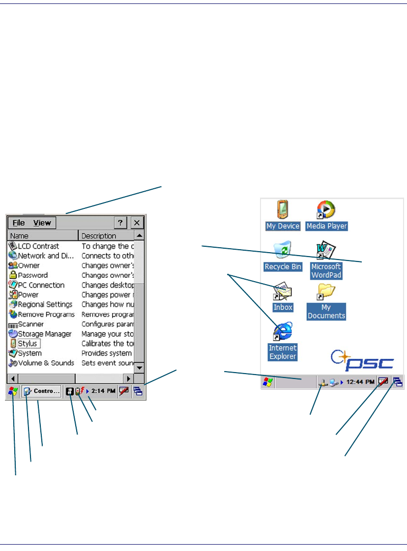
Tap the Start button ( ) to open the Start menu. The Start
menu includes access to Programs, Favorites, Documents, Settings, Help, and the
Run command. From Settings you can access the Control Panel, Network and
Dial-up Connections, and the Taskbar and Start Menu configuration.
System Tray.
The System Tray contains icons for key presses, utilities and
applets running in the background. Tap the small arrow(s) in the System Tray
to view icons for current input mode(s), keypress, power management, and
network connections.
Soft Input Panel.
Refer to Soft Keypad/Input Panel, below, for details.
Extras Menu.
Tap the Extras Menu button at the far right of the Task bar to
select from a list of open applications or to access the desktop while leaving a
program open.
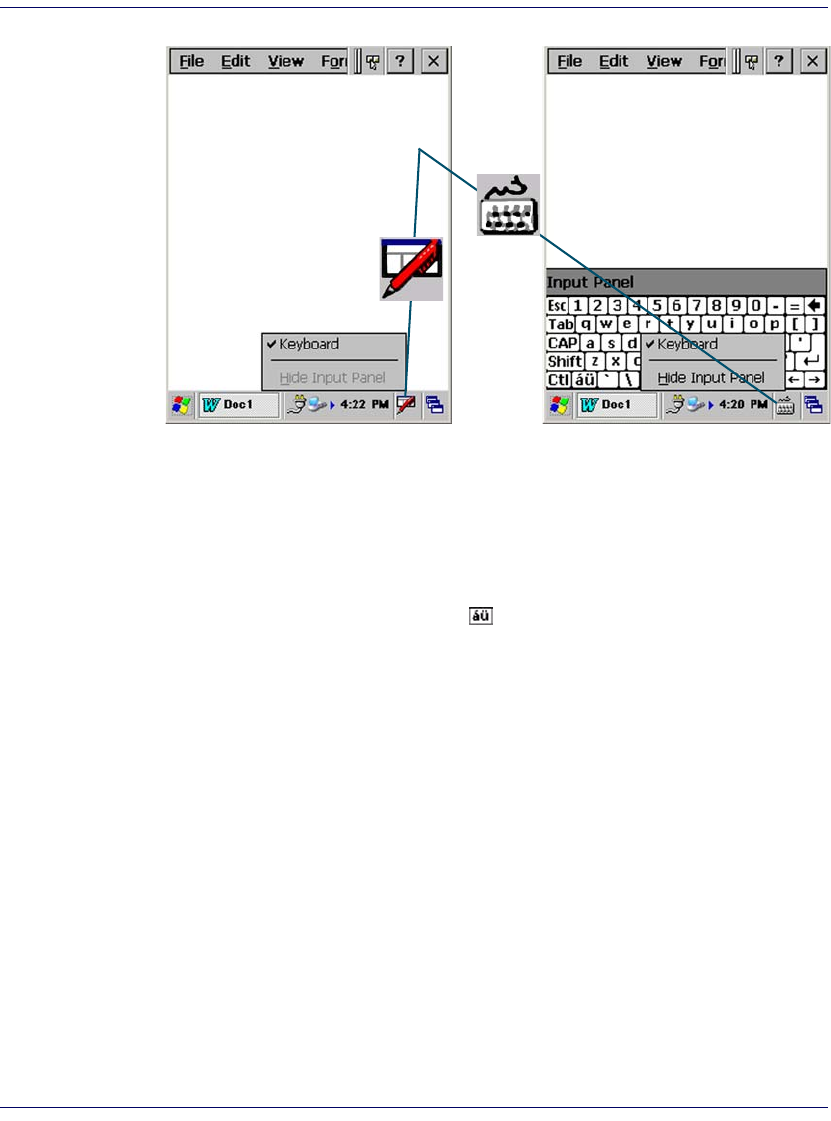
Soft Keypad/Input Panel
In applications that accept keyed input, the soft input panel (SIP) can be used
to enter data using the stylus. The SIP is a digital, QWERTY-style keyboard.
Entering Data
22 Falcon® 4400 Series with Windows® CE
Figure 13. Soft Input Panel
To open the SIP:
Tap the Keyboard icon to open the menu and select Key-
pad from the pop-up menu to open the keyboard
To close the SIP:
Tap the Keyboard icon to open the menu and select Hide
Input Panel to close the keyboard
Use the stylus to select letters, numbers, or symbols from the Soft Input Panel
for the current application. Tap the key to change the keypad to show
international letters.
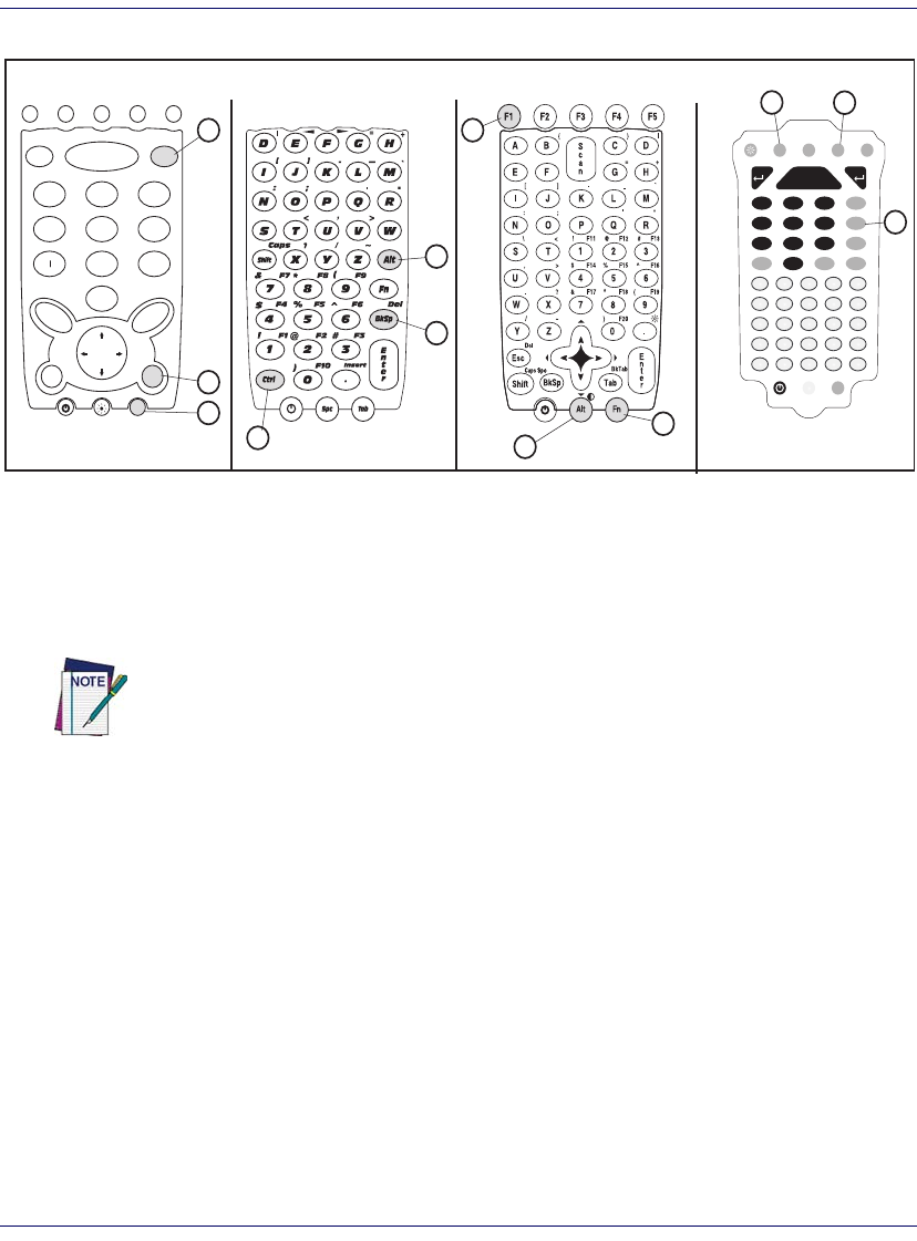
Keypads
Overview
The Falcon is available with several different keypad models:
• 26-Key Keypad on page 25
• 48-Key Keypad on page 27
• 52-Key Keypad on page 28
• 52-Key Numbers Up (NU) Keypad on page 29
• 5250 Keymap on page 29
Refer to the PRG for information on configuring the keypads.
Soft Input Panel
Keyboard Icons

Entering Data
Quick Reference Guide 23
Keypad Attributes
There are a number of keys that are common to the different keypad models.
Table 4 lists special function keys that are found on several keypads, as well as
those which are unique to specific keypads.
Table 4. Keypad Overview - Special Keys
System Tray Keyboard Indicators
The System Tray Keyboard Indicators are located at the bottom of the display
in the Task bar. The most recently activated state is in the left position if more
than one state is active.
Key Name Keypad Model(s) Function/Description
<Alpha> 26-key Press <Alpha> to access lower case alpha characters and symbols on the
26-key keypad.
Alpha-
Numeric
Keys
All
In Normal mode, use the alpha-numeric keys to enter numbers and letters.
In Shift and CAPS modes, the alpha-numeric keys enter upper case let-
ters.
Backlight All <Backlight> toggles the Backlight on or off when you press it.
<Fn> All Press <Fn> to enter the FN input state. Use FN mode to access additional
features and operations.
<Power> All
Press Power to put the Falcon into sleep (suspend) mode if it is currently
running, and wake up (resume) the Falcon if it was in sleep mode. Press
and hold it briefly to turn off the Falcon.
<Scan>
26-key
52-key
52-key NU
Press <Scan> to activate the laser scanner.
4-Way
Rocker
Key
26-key
52-key
Press the edge of the 4-way rocker key to move the cursor or highlighted
text entry during a menu/list selection. In a text window:
• The <Up> arrow moves the cursor up one line.
• The <Right> arrow moves the cursor to the right one character.
• The <Down> arrow moves the cursor down one line.
• The <Left> arrow moves the cursor to the left one character.
<Ctrl> 48-key
52-key NU
<Ctrl> allows keyboard shortcuts like a PC. You can perform functions
such as Save (Ctrl-s) and Find (Ctrl-f). Toggle on and off for text formatting
(for example, Ctrl-b for bold, Ctrl-i for italics, Ctrl-u for underline).
<Alt>
48-key
52-key
52-key NU
Press <Alt> to enter the Alt input state. Use Alt mode to access application
menus.
<Shift>
48-key
52-key
52-key NU
Press <Shift> to enter Shift input states. Use Shift mode to output upper-
case characters and punctuation (identified over number keys).

Entering Data
24 Falcon® 4400 Series with Windows® CE
•The icon is displayed if either Shift or CAPS mode is active.
• If more than two states are active at the same time, only the last two
states are displayed in the System Tray.
Scroll between icons to view the active modes.
Table 5. Input States and their System Tray Indicators
Icon State Keypad
Model(s) Function
Normal
(Numeric)
Mode
26-key Present only on keypads with an Alpha key. It appears when Alpha or CAPS
modes are not on.
Alpha
Mode 26-key
Press <Alpha> to enter lower case alpha characters and symbols. When in Alpha
mode, the current alpha character is displayed by a system tray keyboard indica-
tor.
Alpha mode is persistent, which means that the system stays in Alpha mode until
you press <Alpha> again.
CAPS
Mode
26-key
Press <Fn> + <Alpha> to activate CAPS mode. CAPS mode generates upper
case alpha characters A-Z.
CAPS mode is persistent; press <Fn> + <Alpha> again to generate lower case
characters. Punctuation keys are not affected.
48-key
52-key
52-key NU
Press <Fn> + <SHIFT> to activate Caps mode. Caps mode generates upper
case alpha characters A-Z.
CAPS mode is normally persistent; you must press <Fn> + <SHIFT> again to
generate lower case characters. Punctuation keys are not affected. If CAPS is
active, and SHIFT is active, no icon is displayed.
Fn Mode
26-key
Press <Fn> to enter FN mode.
<Fn> is independent of the <Alpha> key. Use FN mode to access the features
and operations on the keypad.
48-key
52-key
52-key NU
Fn mode converts alpha keys to punctuation and function keys. Fn mode is acti-
vated by pressing <Fn>.
Shift
Mode
48-key
52-key
52-key NU
Shift mode converts characters to upper-case letters or punctuation. Activated by
pressing <Shift>. This state expires after a normal key is pressed unless the
<Shift> key is held down.
Toggles to make the next alpha character capitalized. If Shift state is active when
the Caps State is active, no icon is displayed.
Entering Data
Quick Reference Guide 25
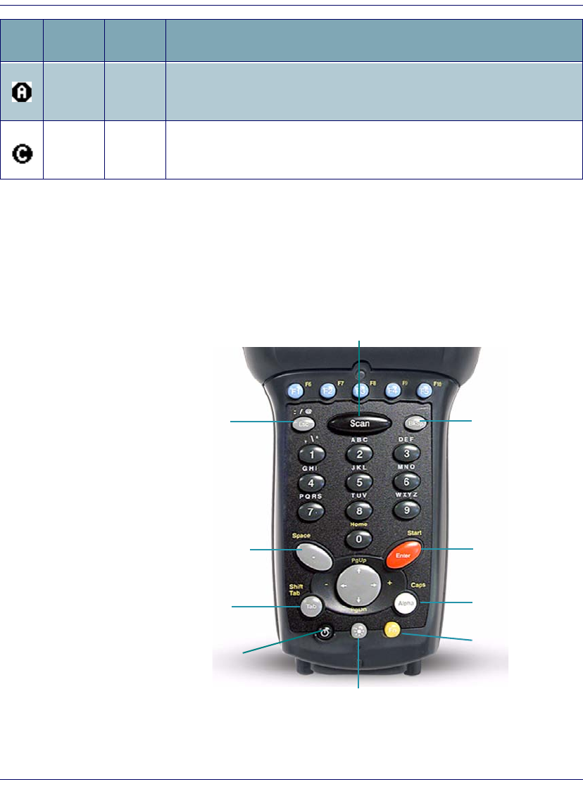
26-Key Keypad
The 26-key keypad is organized like a cell phone, with multi-tap access to
alpha characters on numeric keys (see Figure 14). Use the ten (10) alpha-
numeric keys and the <ESC> key to type letters, numbers, and symbols listed in
Table 6 on page 26.
Figure 14. 26-Key Keypad
Alt Mode
48-key
52-key
52-key NU
Alt mode converts keys to system keys that allow users to access the menu. Acti-
vated by pressing <Alt>. This state expires after a normal key is pressed unless
the <Alt> key is held down.
Ctrl Mode 48-key
52-key NU
<Ctrl> allows keyboard shortcuts. You can perform functions such as Save (Ctrl-
s) and Find (Ctrl-f). Toggle on and off for text formatting (for example, Ctrl-b for
bold, Ctrl-i for italics, Ctrl-u for underline).
Icon State Keypad
Model(s) Function
Scan
Alpha (Caps)
Enter
Fn
Tab
. (Space)
Esc BkSp
Backlight
Power

Entering Data
26 Falcon® 4400 Series with Windows® CE
26-Key Functions.
Most of the keys on the keypad of the Falcon have more
than one function. To access the secondary features and functions, you must
first press another key to access the desired input state.
Only one system tray icon is visible at a time. The most recently activated state
is in the left position of the system tray if more than one state is active.
Alpha-Numeric Keys.
Press the keys in Table 6 once, twice, or more times
to cycle through the alpha letters and symbols until the desired character
appears in the system tray. After the last letter or symbol in the sequence for
that key, the next keypress will generate the first letter or symbol in the
sequence.
Table 6. 26-Key Keypad Alpha Characters and Symbols
Normal
Mode Alpha Mode
Key First
Keypress
Second
Keypress
Third
Keypress
Fourth
Keypress
Fifth
Keypress
<ESC> : / @ : /
<1> , \ * , \
<2> A B C A B
<3> D E F D E
<4> G H I G H
<5> J K L J K
<6> M N O M N
<7> P Q R S P
<8> T U V T U
<9> W X Y Z W
Entering Data
Quick Reference Guide 27
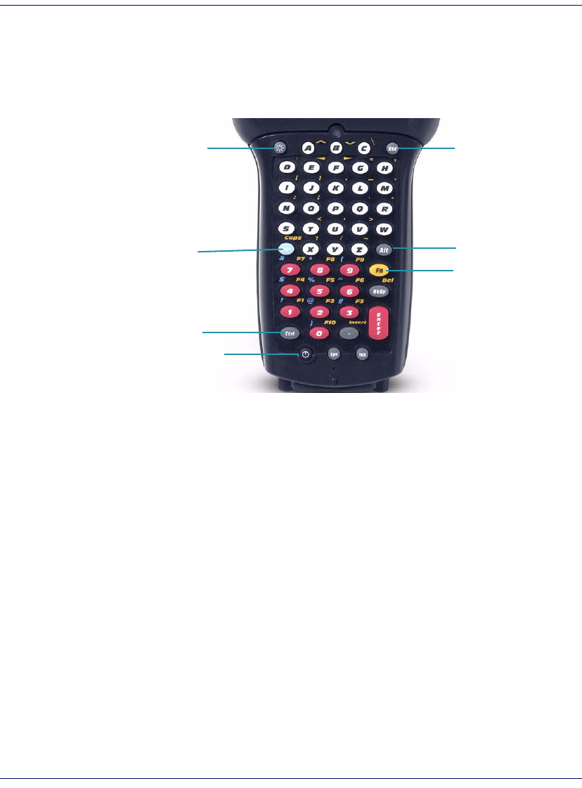
48-Key Keypad
The 48-key keypad is designed to allow you to type all letters and numbers
without requiring multiple key presses.
Figure 15. 48-Key Keypad
Some of the keys on the 48-key keypad of the Falcon have more than one
function. To access the secondary features and functions, you must first press
another key to access the desired input state. See Table 4 on page 23 for fur-
ther information.
48-Key Functions
Press the <Backlight> key to toggle the backlight on or off. To adjust the bright-
ness press <FN><Backlight>. Press <Enter> to accept the changes.
48-Key Input States
The input states for the 48-key keypad are <Caps>, <Shift>, <Ctrl>, <Alt>, and
<Fn>. Each state is described in Table 5 on page 24.
Fn
Esc
Alt
Shift
(Caps)
Ctrl
Backlight
Power
Entering Data
28 Falcon® 4400 Series with Windows® CE
52-Key Keypad
The standard 52-key keypad is designed to allow you to type all letters and
numbers without requiring multiple key presses.
Figure 16. 52-Key Keypad
Some of the keys on the keypad of the Falcon have more than one function. To
access the secondary features and functions, you must first press another key to
access the desired input state. See Table 4 on page 23 for more information.
52-Key Functions
Press <Fn>+< . > (period/decimal) to toggle the backlight on or off. To adjust
the contrast, press <Fn>+<Alt> or select Start > Settings > Backlight. Press <Enter>
to accept the changes.
Accessing FN and ALT Modes
The input states for the 52-key keypad are <Caps>, <Shift>, <Alt>, and <Fn>.
Each is described in Table 5 on page 24.
Alt
Fn
Power
Shift
. (Backlight)
Scan
Scanning Bar Codes
Quick Reference Guide 29
52-Key Numbers Up (NU) Keypad
The full alphanumeric 52-Key Numbers Up (NU) keypad brings frequently
used keys into a more ergonomic position, and is available with the 5250 TE
overlay.
Figure 17. 52-Key NU Keypad
5250 Keymap
The 5250 keymap is designed to provide the keyboard functions needed to
run 5250 terminal emulation software.
The 5250 keymap is available with either the 48-key, 52-key, or 52-key NU
model.
Scanning Bar Codes
Laser Scanning
To use the scanning function on units containing a laser scanning module,
complete the following steps:
1. Select and open a bar code application, such as Microsoft® WordPad.
Alt
Fn
Power
Shift
Backlight
Scan
Esc
Ctrl
Caps
Space
Scanning Bar Codes
30 Falcon® 4400 Series with Windows® CE
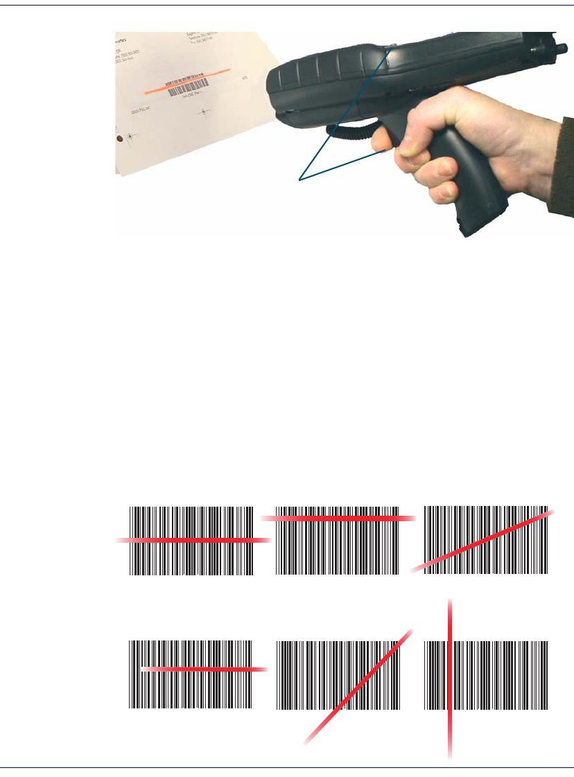
Figure 18. Scanning a Bar Code
2. Aim the scan window at the bar code following the guidelines outlined
in Figure 19.
3. Press <Scan> on the keypad (26, 52 or 52-key NU) or the Scan Trigger
on the handle. The laser scans as long as you hold the button or trigger,
or for 10 seconds, or until a good scan is obtained.
4. Aim the laser beam at the center of the bar code.
• Position the unit close to bar code when scanning small bar codes.
• Position it at a distance when scanning larger bar codes.
• The laser is disabled after you release the key or after 10 seconds,
or once a good scan is obtained.
Figure 19. Laser Beam Positions
Press <Scan> on the keypad (26, 52 or 52-key
NU) or the Scan Trigger to initiate a scan with
the Falcon.
Correct Scanning Positions
Incorrect Scanning Positions
Ideal positioning A bit high, will read correctly A bit angled, will read correctly
Positioned too far to the right. Will
not read entire bar code.
Too angled; cannot read the
entire bar code.
Bar code will not read. The
scanner should be posi-
tioned perpendicular to
the bar code bars.
Scanning Bar Codes
Quick Reference Guide 31
5. The device beeps and the green LED indicator comes on until the trig-
ger is released. The green LED and the beep tone indicate a good read.
6. The bar code data is entered in the current application.
7. Once a bar code is read successfully, the scanner turns off automatically.
Refer to the section on Scanner Configuration in the PRG to modify the
default settings.
Bar Code Scanning with 2D Imager
Scanning bar codes with the 2D imaging device is similar to scanning with a
laser scanner. The operation and configuration of the scanner is performed in
the same way as laser scanning devices. Trigger behavior and scanning time-
outs are the same as laser scanning devices.
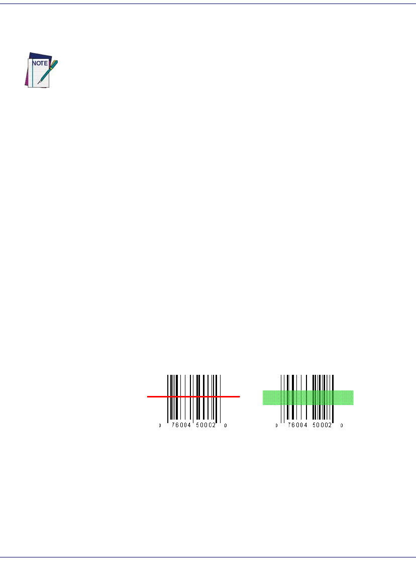
Scanning Differences
Scanning Aimer
The imager contains an aiming beam rather than a red laser. The aiming beam
mimics a laser line for purposes of orienting the imager to a bar code. Figure
20 shows how the aiming beam visually differs from the laser beam in laser
scanning devices.
Figure 20. Laser vs. Imaging beam
Note that the aiming beam for the imager is green, rather than red.
If the bar code scan failed, adjust the reading angle or distance. Make sure that
the laser beam scans across all bars of the bar code. Refer to Figure 19.
Laser Aiming Beam
Image Capture
32 Falcon® 4400 Series with Windows® CE
Orientation
Rotational orientation does not affect the imager module's ability to read bar
codes. For example, the imager can read a bar code when the aimer beam is
parallel to the lines of the bar code. What is important is the location of the
aimer in relation to the center of the bar code. The aiming beam should be
centered over the bar code, but it can be positioned in any direction for a good
read.
Figure 21. Aiming Beam Positioning
The aiming beam is smaller when the imager is closer to the code and larger
when it is farther away. Symbologies with smaller bars or elements (mil size)
should be read closer to the unit. Symbologies with larger bars or elements
(mil size) should be read farther from the unit. To scan a label, hold the imager
at an appropriate distance from the target, pull the trigger, and center the aim-
ing beam on the symbol.
Scanning Illumination
Another feature that can be enabled for 2D scanning is an array of illumina-
tion LEDs. These LEDs provide illumination in dark environments and can
improve scanning performance under certain lighting conditions. By default,
the illumination LEDs are turned on. Illumination LEDs can be disabled
using the PDT parameters. See the PRG for complete information on pro-
gramming the LEDs.
Image Capture
The 2D imager can be used for capturing, manipulating, and transferring
images.
You can set options for image capture in the Imaging Control Panel. Various
image formats can be selected, including TIFF, JPEG and BMP. You can also
Linear bar codes 2D Matrix symbol
Flash Memory
Quick Reference Guide 33
scale, rotate, and modify image quality settings. See the PRG for detailed infor-
mation on using the Falcon 2D for image capture.
Flash Memory
In addition to the RAM-based storage standard on Windows CE terminals,
the Falcon is also equipped with Datalight FlashFX Flash-based application
and file storage area. Refer to the PRG for more information.
Saving to Flash
To save an application or data to the Flash Memory, from your current appli-
cation, select File > Save As > navigate to the FlashFX Disk location as described
below.
Flash FX Location
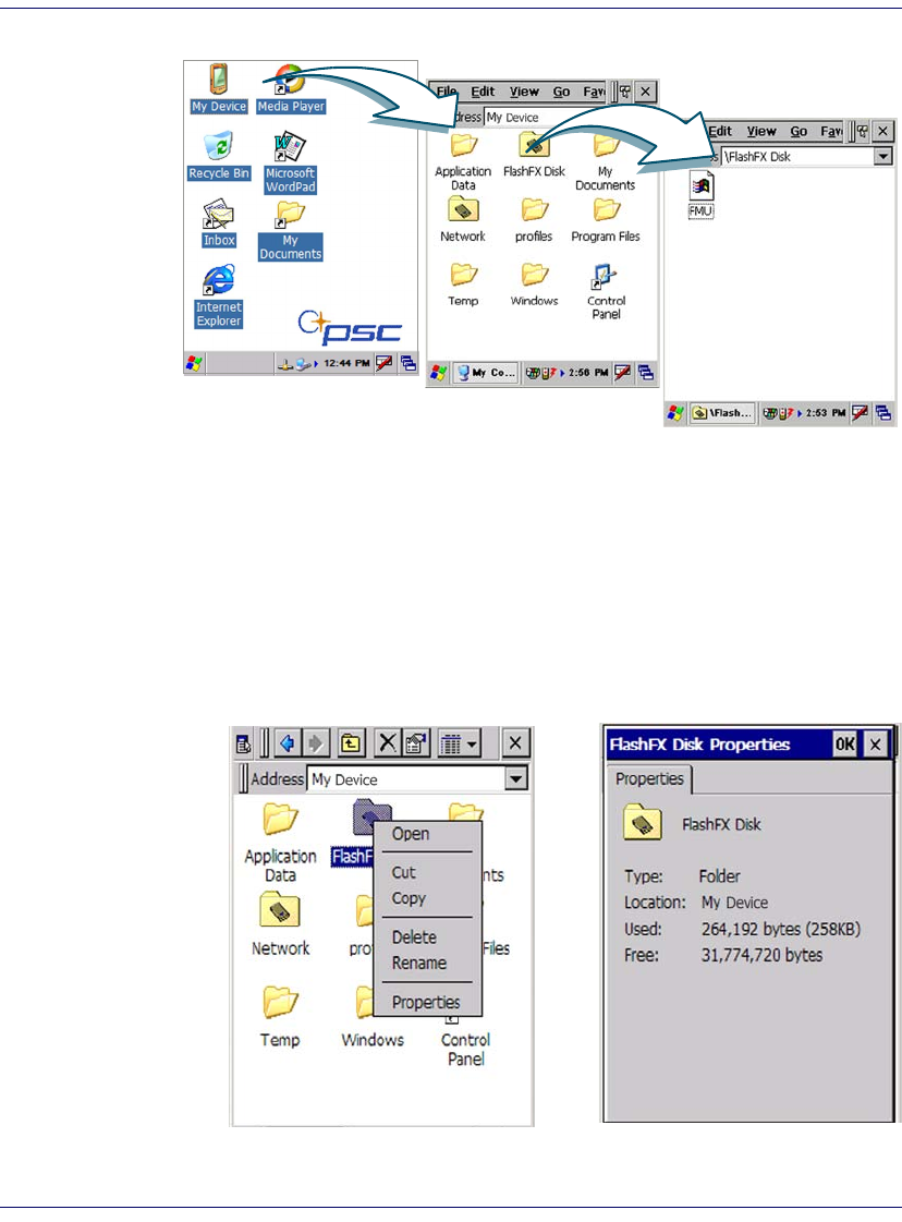
To access the contents of Flash Memory:
1. Double-tap the My Device icon on the desktop.
2. Double-tap the FlashFX Disk icon to view the FlashFX Disk.
The FlashFX storage memory persists across all reset (warm/cold reboot) condi-
tions and software / firmware updates.
Because of this, PSC very strongly recommends installing all applications,
applets, programs, and important data files to the FlashFX disk of the Falcon.
If an application or a data file is only installed or saved in RAM, a hard reset will
result in the loss of that application or data file.
Flash Memory
34 Falcon® 4400 Series with Windows® CE
Figure 22. Location of the FlashFX Disk
FlashFX Disk Size
The size of the FlashFX disk will vary, depending upon several factors, such as
the size and number of currently running applications and the amount of
memory currently consumed by the OS.
To view the current size of Flash Memory:
1. Double-tap the My Device icon on the desktop. (See Figure 22).
Figure 23. Size of FlashFX Disk
B
A
Context Sensitive Help
Quick Reference Guide 35
2. Press and hold the FlashFX Disk directory with the stylus, and select
Properties from the pop-up menu (see Figure 23A).
3. The FlashFX Properties dialog opens (see Figure 23B). The number
following Free is the amount of memory currently available on the
Falcon.
Table 7. FlashFX Disk Specifications
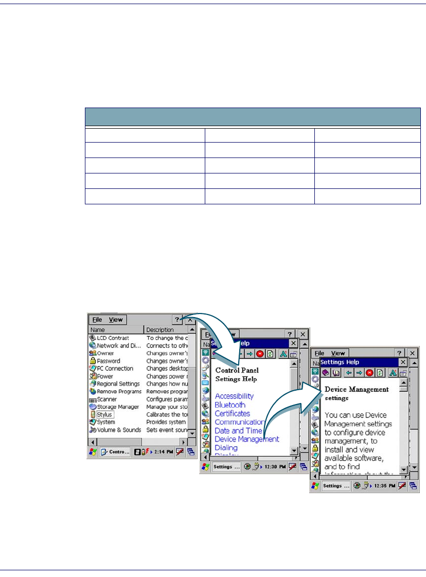
Context Sensitive Help
Microsoft Windows CE context sensitive help is available wherever a “?” but-
ton appears in the upper right hand corner of the window. Press the “?” button
to open the context help window.
Figure 24. Using Windows CE Context Sensitive Help
To open context sensitive Help, select/tap the “?” in the upper right corner of
most screens. Select/tap the desired item from the list of hot links.
FlashFX Disk Specifications
Total Flash size 64.0 MB 128 MB
OS/Firmware uses up to 32.0 MB 32 MB
FlashFX size 32.0 MB 96 MB
File storage size 31 MB (approximate) 90 MB (approximate)
Running Application 22 MB (approximate) 81 MB (approximate)

Resetting the Falcon
36 Falcon® 4400 Series with Windows® CE
Resetting the Falcon
There are two reset methods for the Falcon.
• A warm reset terminates a “hung” application, and clears the working
RAM, but preserves the file system.
• A cold reset forces all applications to close and clears working RAM
and files not resident on the FlashFX Disk.
Warm Reset
A warm reset is a transition from the on or idle condition that closes all appli-
cations, clears the working RAM, but preserves the file system.
If an application “hangs,” initiate a warm reset to terminate the application.
Procedure to Warm Reset
The reset procedure varies, depending upon the keypad on your Falcon. The
first two keys of the sequence can be pressed in any order, but the unit will not
reset until they both are held down and then the third key (<Bksp>, <F1> or
<Del>) is pressed. All three keys must be held down for the unit to reset. Refer
to Figure 25 on page 37 for the location of the reset keys.
26-Key Falcon.
Press and hold: <FN>+<Alpha>+<Bksp>.
48-Key Falcon.
Press and hold: <Ctrl>+<Alt>+<Bksp>.
52-Key Falcon.
Press and hold: <Alt>+<FN>+<F1>.
52-Key NU Falcon.
Press and hold: <Ctrl>+<Alt>+<Del>.
CAUTION
PSC recommends that you always attempt a warm reset before initiating a cold
reset. Once you initiate a cold reset, all applications are forcibly closed and work-
ing RAM and files are cleared.
It is a good idea to store important data in FlashFX storage for this reason. Refer
to Flash Memory on page 33 for more information on Flash Memory.
DO NOT use a sharp object on the reset button. Sharp objects can puncture the
keypad, disabling the reset function, rupturing the Falcon’s industrial seal, and
voiding your warranty.
Resetting the Falcon
Quick Reference Guide 37
Figure 25. Warm Reset
After Warm Reset
• The splash screen will appear briefly.
• The desktop appears with the application shortcuts on the screen.
• RF Network PC Card (if present) connects to the network system.
Cold Reset
A cold reset is a complete reset of the Falcon in which all applications are forc-
ibly closed and working RAM is cleared.
13
2
6
5
4
789
0
F1 F2 F3 F4 F5
Scan
Esc BkSp
.
Enter
Ta b
Fn
Alpha
S h ift
Ta b Caps
Start
Hom e
Space
G H I
P Q R S W X Y ZT U V
J K L
A B C
: / @
, \ *
D E F
M N O
26-Key 52-Key / 5250
48-Key
1
2
3
1
1
3
2
2
3
Hold down 1 & 2 ...then press 3
Caps
BkSpBkSp
Del
Shift
Ctrl
Fn
Spc
Alt
Esc
1
ABCDE
FGHIJ
KL
M
NO
PQRST
UV
W
Z
XY
23
456
77 8
0.
9
TabTab
EnterEnter
Scan
12
3
52-Key NU
The custom settings in the registry are persistent.
Resetting the Falcon
38 Falcon® 4400 Series with Windows® CE
Reason to Cold Reset. Press the <Reset> button when the Windows CE
operating system locks up and the warm reset command does not work.
Procedure to Cold Reset. To perform a cold reset, insert a paper clip
into the cold <Reset> button while pressing the <Power> button (refer to Figure
26).
Figure 26. Cold Reset
After Cold Reset
When a Falcon goes through the cold reset sequence, it clears the working
RAM and initializes the file system. You will lose any applications and data
which are not stored in persistent flash memory (refer to Flash Memory start-
ing on page 33).
CAUTION
PSC recommends that you always attempt a warm reset before initiating a cold
reset. Once you initiate a cold reset, all applications are forcibly closed and work-
ing RAM and files are cleared.
Any applications, files, or data in RAM will be lost if you cold reset. Only the appli-
cations and the files in the FlashFX Disk are preserved upon a cold reset. Refer to
Flash Memory on page 33 for more information on preserving applications and
files with the persistent FlashFX storage memory.
Do not use a sharp object on the cold reset button as this can puncture the key-
pad, disabling the reset function, rupturing the Falcon industrial seal, and voiding
your warranty. PSC recommends using a straightened paper clip.
13
2
6
5
4
789
0
Scan
Esc BkSp
.Enter
Tab
Fn
Alpha
Shift
Tab Caps
Start
Home
Space
G H I
P Q R S W X Y ZT U V
J K L
A B C
: / @
, \ * D E F
M N O
Cold Reset
Button Access
Maintaining the Falcon
Quick Reference Guide 39
• The splash screen will appear after a short period.
• Recalibrate the touch screen or press <ESC> to circumvent calibration.
• The desktop appears with the application shortcuts on the screen.
• RF Network PC Card (if present) connects to the network system.
Maintaining the Falcon
With normal use, the Falcon, Dock, Four-Slot Dock and battery chargers
require no maintenance. For trouble-free service, observe the following tips
when using the Falcon:
• To prolong its life and avoid problems, keep the Falcon clean. Use a
clean, soft cloth dampened with a mild, dilute cleanser.
• If you need to clean the display, clean it with a lens cloth or other soft
cloth dampened with a mild, dilute cleaning solution.
The custom settings in the registry are persistent.
CAUTION
Never use a pen, pencil, or other sharp object on the display/touch screen.
Use only the supplied stylus or plastic-tipped pens intended for use with a
touch-sensitive screen.
Do not immerse the Falcon, docks, or battery chargers in liquid.
Do not use abrasive paper/cloth or abrasive/corrosive cleaners to clean the
unit.
WARNING
Do not use a sharp object to Reset; use a paper clip. A sharp object can
puncture the keypad, disabling the reset function, rupturing the industrial
seal, and voiding your warranty. Refer to the Falcon 4400 Quick Reference
Guide for reset instructions.

Troubleshooting
40 Falcon® 4400 Series with Windows® CE
Troubleshooting
Refer to the Falcon 4400 Windows CE PRG for more information.
Table 8. Troubleshooting Problems, Causes, and Solutions
Problem Possible Cause Solution
The Falcon does not turn
on.
The battery pack is not installed
properly.
Ensure the battery is installed properly.
System failure. Perform a cold reset. Refer to Resetting the Falcon
starting on page 36.
During boot, the terminal
beeps twice and the system
stays blank.
Firmware flash memory has
been corrupted.
Re-download the firmware using the FUU in bootload
mode. Refer to the PRG.
Rechargeable battery pack
did not charge.
Battery failure. Replace the battery. If the Falcon terminal still does not
operate, try a warm reset then a cold reset; refer to
Resetting the Falcon starting on page 36.
The Falcon was removed from
the dock while battery was
charging.
Insert the Falcon in dock and begin charging. The bat-
tery pack and backup battery require 4 hours to fully
charge.
Characters are not visible
on the display.
The Falcon is not powered on. Press <PWR>.
The ambient room light is too
dark or low.
Turn on the backlight. Refer to the PRG.
No sound is audible. Volume setting is low or turned
off.
Adjust the sound by going to Start > Settings > Con-
trol Panel > Volume & Sounds
OR
Scan a bar code from the PRG.
The Falcon turns itself off. The Falcon is inactive. The Falcon turns off after a period of inactivity. You can
set duration from one to 30 minutes. Refer to the PRG
to modify the default settings.
During data
communication, no data
was transmitted, or
transmitted data was
incomplete.
The Falcon was removed from
the dock or unplugged from host
PC during communications.
Replace the terminal in the dock, or replace the serial
cable, and retransmit.
Incorrect cable configuration. See your System Administrator.
Communication software was
incorrectly installed or config-
ured.
Perform setup as described in the PRG.

Troubleshooting
Quick Reference Guide 41
The Falcon does not accept
scan input.
The scanning window is dirty. Carefully wipe the scanning window with a soft, clean
cloth. Do not use abrasive cleaners.
The scanning application is not
loaded.
Verify that the unit is loaded with a scanning applica-
tion. See your System Administrator.
Unreadable bar code. Be sure the symbol is not defaced.
Distance between exit window
and bar code is incorrect.
Be sure you are within proper scanning range.
The Falcon is not programmed
for that symbology.
Be sure the terminal is programmed to accept the type
of bar code you are scanning. Try using FF3A to turn
on maximum defaults, as described in “Programming
Parameters” in the Falcon 4400 PRG.
The Falcon is not programmed
to generate a beep.
If you are expecting a beep on a good decode and
don’t hear one, check that the application is set to gen-
erate a beep on good decode.
Battery is low. If the scanner stops emitting a laser beam when you
press the trigger, check your battery level. Refer to the
PRG.
Note: If the scanner is still not reading sym-
bols, contact your distributor or PSC Inc.
The UPC/EAN extension
(supplemental label) is not
always scanned.
Laser beam only crosses over
base of UPC/EAN label.
Set the Read Verification for extensions (parameter
0528) to a value lower than the Read Verification for
the base label. See the PRG.
Problem Possible Cause Solution

Troubleshooting
42 Falcon® 4400 Series with Windows® CE
The Spare Battery LED on
the dock is flashing RED.
Time-out fault: the spare bat-
tery pack charging has
exceeded the maximum time-
out period.
In either case, if the Spare Battery LED is flashing red,
do the following:
1. Disconnect the AC adapter from the dock.
2. Remove the spare battery pack and the Falcon from
the dock.
3. Connect the AC adapter to the dock.
4. If the Spare Battery LED is flashing red, there is a
problem with the dock. Disconnect the AC adapter
from the dock and contact a service technician.
5. If the Spare Battery LED is off, insert a different
spare battery pack in the dock.
6. If, in the course of charging the spare battery, the
Spare Battery LED is flashing red, there is a problem
with the dock. Disconnect the AC adapter from the
dock and contact a service technician.
7. Otherwise, there is a problem with the first spare
battery pack. Discontinue use of the first spare bat-
tery pack. Refer to the PRG for instructions on bat-
tery disposal.
Over-voltage fault: the spare
battery pack charging has
exceeded the maximum charge
voltage of the battery.
Problem Possible Cause Solution
Troubleshooting
Quick Reference Guide 43
RF Connectivity Troubleshooting
Does the Falcon
respond to a PING
command from
a PC?
NO
Does the Falcon
associate with the AP
?
YES
display an error during the
boot process?
Gather facts:
•
Falcon type
•
AP & RF card brand (ensure latest version of firmware installed)
•
Host type
•
Software type
•
Software version (ensure latest version is installed)
•
Frequency and duration of issue
Can you ping the
host from a PC on same
subnet
?
Can you ping the
Falcon from the AP
?
Potential Problems:
•
Security Issue – Check
SSID, WEP, LEAP settings
•
Range Issue
Potential Problems:
•
IP Address Issue
•
Check security settings
Potential Problems:
•
Host unavailable
Potential Problems:
•
IP address issue (duplicate address on Falcon). Turn off the Falcon and
attempt PING again
•
Run tracert command to determine location of breakdown of connectivity.
RF connectivity
obtained. See your
software manual for
further information or
contact PSC technical
support.
Does the Falcon
connect to the host
?
Does the Falcon
START
NO
NO
NO
YES
YES
YES
YES
YES
NO
NO
: Potential Problems
Ping Falcon from
host or use tracert to
determine the location
of the breakdown in
communication.
(For more information on the Ping command, go to the command prompt on the PC and type PING. For more information on the
trace route command, go to the command prompt on the PC and type tracert.)
Contact Tech Support.

Technical Support
44 Falcon® 4400 Series with Windows® CE
Technical Support
PSC Website Support
The PSC website (www.psc.com) is the complete source for technical support
and information for PSC products. The site offers the PSC TekForum, prod-
uct support, product registration, warranty information, product manuals,
product tech notes, software updates, demos, and instructions for returning
products for repair.
PSC Website TekForum
Search for information on the TekForum by clicking on the Support link on
the PSC home page. Browse the TekForum to find answers to your questions
about common technical issues.
Reseller Technical Support
An excellent source for technical assistance and information is an authorized
PSC reseller. A reseller is acquainted with specific types of businesses, applica-
tion software, and computer systems and can provide individualized assistance.
Telephone Technical Support
If you do not have internet or email access, you may contact PSC technical
support at (541) 349-8281.

Quick Reference Guide 45
Appendix A:
PSC Falcon
®
Windows
®
CE Series
End User License Agreement
Notice to End User: The PSC Product you have acquired contains Software, which is integral to the product’s operation. This
Software is being provided to you under license, subject to the terms and conditions of this Agreement. If you use the PSC Prod-
uct, you will be deemed to have accepted the terms and conditions of this Agreement. If you do not intend to be bound to the
terms of this Agreement, PSC is not willing to license the Software to you, you may not use the PSC Product or the Software,
and you must contact the party from whom you acquired the PSC Product for instructions.
This End User Software License Agreement (“Agreement”) is a legally binding agreement governing the licensing of the Soft-
ware and Documentation by PSC Inc. and its wholly owned subsidiaries and affiliates (“PSC”) to the entity or person who has
purchased or otherwise acquired a PSC Product (“End User”). For purposes of this Agreement, any software that is associated
with a separate end-user license agreement is licensed to you under the terms of that license agreement. PSC and End User
hereby agree as follows:
1. Definitions.
1.1 “Documentation” means materials such as user’s guides, program reference guides, quick reference guides, manuals, or
similar materials associated with or related to the PSC Product, whether in printed, “online”, or other form.
1.2 “Proprietary Information” means: (a) source code, object code, software, documentation, and any related internal design,
system design, data base design, algorithms, technology, technical data or information, implementation techniques, and trade
secrets related to the Software, (b) any other trade secrets marked appropriately or identified as proprietary or confidential, and
(c) any information that End User, under the circumstances, should recognize as confidential. Proprietary Information does not
include any information that the receiving party can establish was (1) in the public domain, (2) already in the receiving party’s
possession or rightfully known prior to receipt, (3) rightfully learned from a third party not in violation of any other's proprietary
rights, or (4) independently developed without access to Proprietary Information.
1.3 “PSC Product” means PSC’s Falcon® Windows®CE .NET Series, including all preloaded Software in or provided in connec-
tion with the PSC Product and all Documentation related to such product, which has been purchased or otherwise acquired by
End User, whether obtained directly or indirectly from PSC.
1.4 “Software” means any software or computer programs of PSC or its third party licensors in machine readable form which is
either preloaded in or provided in connection with the PSC Product, whether obtained directly or indirectly from PSC, including
any related update or upgrade such as enhancements or modifications.
2. Scope Of License Granted.
2.1 PSC grants to End User a non-exclusive, non-transferable, perpetual license to use the Software, solely on a PSC Product,
in machine-readable form only, solely for End User's internal business purposes. This Agreement does not convey ownership of
the Software to End User. Title to the Software shall be and remain with PSC or the third party from whom PSC has obtained a
licensed right. As used in this Agreement, the term “purchase” or its equivalents when applied to the Software shall mean
“acquire under license.”
2.2 End User shall not copy, modify, decompile, disassemble, reverse engineer, or otherwise reproduce or remanufacture the
Software, whether modified or unmodified, nor sell, assign, sublicense, distribute, lend, rent, give, or otherwise transfer the Soft-
ware to any other person or organization, for purposes other than as expressly provided in this Agreement, or to the extent spe-
cifically allowed under foreign law solely for the purposes of interoperability, without PSC’s prior written consent.
3. Transfers, Support.
3.1 Any copying, installing, reproduction, remanufacture, reverse engineering, electronic transfer, or other use of the Software
on other than a PSC Product will be a material breach of this Agreement.
3.2 End User shall not sell, assign, sublicense, distribute, lend, rent, give, or otherwise transfer a PSC Product containing Soft-
ware to any third party unless such third party agrees with PSC in writing to be bound by the terms and conditions of this Agree-
ment. Any such transfer of a PSC Product absent such agreement shall be null and void.

Appendix A: PSC Falcon® Windows® CE Series End User License Agreement
46
Falcon® 4400 Series with Windows® CE
3.3 End User may obtain support for Software from PSC at PSC’s standard support fees and under PSC’s standard support
terms and conditions in effect at the time the support is requested.
4. Intellectual Property.
End User acknowledges that the Software constitutes valuable trade secrets of PSC or PSC’s third party licensors and that the
Software is protected by intellectual property laws and treaties. The license set forth in this Agreement does not transfer to End
User any ownership of PSC’s or its third party licensors' copyrights, patents, trademarks, service marks, trade secrets, or other
intellectual property rights and End User shall have no right to commence any legal actions to obtain such rights. End User shall
not remove, modify, or take any other action that would obscure any copyright, trademark, patent marking, or other intellectual
property notices contained in or on the PSC Product.
5. Proprietary Information.
5.1 End User acknowledges that Proprietary Information is the confidential, proprietary, and trade secret property of PSC and
PSC’s third party licensors and End User acquires no right or interest in any Proprietary Information.
5.2 End User shall not disclose, provide, or otherwise make available the Proprietary Information of PSC or its third party licen-
sors to any person other than End User’s authorized employees or agents who are under confidentiality agreement, and End
User shall not use the Proprietary Information other than in conjunction with use of the PSC Product exclusively for End User’s
internal business purposes. End User shall take steps to protect the Proprietary Information no less securely than if it were End
User's own intellectual property.
5.3 The provisions of this Proprietary Information Section shall survive and continue for five (5) years after the termination of this
Agreement.
6. Limited Warranty.
6.1 PSC warrants that, under normal use and operation, the PSC Product will conform substantially to the applicable Documen-
tation for the period specified in the Documentation. During this period, for all reproducible nonconformities for which PSC has
been given written notice, PSC will use commercially reasonable efforts to remedy nonconformities verified by PSC. End User
agrees to supply PSC with all reasonably requested information and assistance necessary to help PSC in remedying such non-
conformities. For all defects reported to PSC within the warranty period, PSC’s liability is limited to providing End User with one
copy of corrections or responding to End User's problem reports according to PSC's standard assistance practices. PSC does
not warrant that the product will meet End User's requirements or that use of the product will be uninterrupted or error free, or
that PSC's remedial efforts will correct any nonconformance. This limited warranty does not cover any product that has been
subjected to damage or abuse, whether intentionally, accidentally, or by neglect, or to unauthorized repair or unauthorized instal-
lation, and shall be void if End User modifies the product, uses the product in any manner other than as established in the Docu-
mentation, or if End User breaches any of the provisions of this Agreement.
6.2 EXCEPT AS PROVIDED IN THIS AGREEMENT, THE PSC PRODUCT IS PROVIDED “AS IS” AND PSC MAKES NO WAR-
RANTIES OF ANY KIND, EXPRESS OR IMPLIED, WRITTEN OR ORAL, WITH RESPECT TO THE PRODUCT, AND SPECIF-
ICALLY DISCLAIMS THE IMPLIED WARRANTIES OF MERCHANTABILITY AND FITNESS FOR A PARTICULAR PURPOSE.
7. Infringement.
7.1 PSC will defend End User against any claim in a lawsuit that the PSC Product furnished hereunder infringes a United States
patent or copyright of a third party and PSC will pay any damages finally awarded against End User by a court of competent
jurisdiction that are attributable to such claim or will pay End User’s part of any settlement that is attributable to such claim, pro-
vided, that 1) End User notifies PSC promptly in writing of the claim, 2) PSC controls the defense or settlement of the claim, and
3) End User cooperates fully with PSC in such defense or settlement. All notices of a claim should be sent to PSC Inc., 959 Terry
Street, Eugene, OR 97402.
7.2 In the defense or settlement of any such claim, PSC may, at its option, 1) procure for End User the right to continue using the
PSC Product, 2) modify the PSC Product so that it becomes non-infringing, 3) replace the PSC Product with an equivalent prod-
uct not subject to such claim, or 4) provide End User an opportunity to return the PSC Product and receive a refund of the pur-
chase price paid, less a reasonable allowance for use.
7.3 PSC shall have no liability to End User for claims of infringement based upon 1) the use of any PSC Product in combination
with any product which PSC has not either furnished or authorized for use with such PSC Product 2) the use of any PSC Product
designed, manufactured, or modified to the specifications of End User, or 3) End User’s modification of the PSC Product without
written authorization from PSC.
7.4 THE FOREGOING STATES PSC’S COMPLETE AND ENTIRE OBLIGATION CONCERNING CLAIMS OF PATENT, COPY-
RIGHT, OR OTHER INTELLECTUAL PROPERTY INFRINGEMENT, CANCELS AND SUPERCEDES ANY PRIOR AGREE-

Appendix A: PSC Falcon® Windows® CE Series End User License Agreement
Quick Reference Guide 47
MENTS, WHETHER ORAL OR WRITTEN, BETWEEN THE PARTIES CONCERNING SUCH CLAIMS, AND WILL NOT BE
MODIFIED OR AMENDED BY ANY PAST, CONTEMPORANEOUS, OR FUTURE AGREEMENTS OR DEALINGS BETWEEN
THE PARTIES, WHETHER ORAL OR WRITTEN, EXCEPT AS SET FORTH IN A FUTURE WRITING SIGNED BY BOTH PAR-
TIES.
8. Limitation Of Liability.
EXCEPT AS PROVIDED IN SECTION 7, PSC SHALL NOT BE LIABLE FOR ANY CLAIMS AGAINST END USER BY ANY
OTHER PARTY. IN NO EVENT SHALL PSC'S LIABILITY FOR DAMAGES, IF ANY, WHETHER BASED UPON CONTRACT,
TORT (INCLUDING NEGLIGENCE), PRODUCT LIABILITY, STRICT LIABILITY, WARRANTY, OR ANY OTHER BASIS,
EXCEED THE PRICE OR FEE PAID BY END USER FOR THE PSC PRODUCT. UNDER NO CIRCUMSTANCES SHALL PSC
BE LIABLE TO END USER OR ANY THIRD PARTY FOR LOST PROFITS, LOST DATA, INTERRUPTION OF BUSINESS OR
SERVICE, OR FOR ANY OTHER SPECIAL, CONSEQUENTIAL, CONTINGENT, INDIRECT, INCIDENTAL, PUNITIVE, EXEM-
PLARY, OR OTHER SIMILAR DAMAGES, EVEN IF PSC HAS BEEN ADVISED OF THE POSSIBILITY OF SUCH DAMAGES.
9. Government Restricted Rights; International Use.
9.1 Use, duplication, or disclosure of the Software by the U.S. Government is subject to the restrictions for computer software
developed at private expense as set forth in the U.S. Federal Acquisition Regulations at FAR 52.227-14(g), or 52.227-19 or in
the Rights in Technical Data and Computer Software clause at DFARS 252.227-7013(c)(1)(ii), whichever is applicable.
9.2 If End User is using the PSC Product outside of the United States, End User must comply with the applicable local laws of
the country in which the PSC Product is used, with U.S. export control laws, and with the English language version of this Agree-
ment. The provisions of the “United Nations Convention on International Sale of Goods” shall not apply to this Agreement.
10. Termination.
10.1 Either party may terminate this Agreement or any license granted under this Agreement at any time upon written notice if
the other party breaches any provision of this Agreement.
10.2 Upon termination of this Agreement, End User immediately shall cease using any non-preloaded software and shall return
to PSC or destroy all non-preloaded software covered by this Agreement, and shall furnish PSC with a certificate of compliance
with this provision signed by an officer or authorized representative of End User. For preloaded software, End User agrees to
sign a waiver prepared by PSC concerning further use of the preloaded Software. End User’s resumed or continued use of the
preloaded Software after termination shall constitute End User’s agreement to be bound by the terms and conditions of this
Agreement for such use.
11. General Provisions.
11.1 Entire Agreement; Amendment. This document contains the entire agreement between the parties relating to the licensing
of the Software and supersedes all prior or contemporaneous agreements, written or oral, between the parties concerning the
licensing of the Software. This Agreement may not be changed, amended, or modified except by written document signed by
PSC.
11.2 Notice. All notices required or authorized under this Agreement shall be given in writing, and shall be effective when
received, with evidence of receipt. Notices to PSC shall be sent to the attention of the Legal Department, General Counsel, PSC
Inc., 959 Terry Street, Eugene, OR 97402, or such other address as may be specified by PSC in writing.
11.3 Waiver. A party’s failure to enforce any of the terms and conditions of this Agreement shall not prevent the party’s later
enforcement of such terms and conditions.
11.4 Governing Law; Venue: This Agreement and the rights of the parties hereunder shall be governed by and construed in
accordance with the laws of the State of Oregon U.S.A, without regard to the rules governing conflicts of law. The state or federal
courts of the State of Oregon located in either Multnomah or Lane counties shall have exclusive jurisdiction over all matters
regarding this Agreement, except that PSC shall have the right, at its absolute discretion, to initiate proceedings in the courts of
any other state, country, or territory in which End User resides, or in which any of End User's assets are located.
11.5 Attorneys’ Fees. In the event an action is brought to enforce the terms and conditions of this Agreement, the prevailing party
shall be entitled to reasonable attorneys’ fees, both at trial and on appeal.
- END -

48
Falcon® 4400 Series with Windows® CE
Appendix B: Microsoft
®
Windows
®
CE
End User License Agreement
Microsoft® has contractually obligated PSC Inc. to include the following information as part of our software end user license
agreement:
You have acquired a device (“DEVICE”) that includes software licensed by PSC Inc. from Microsoft licensing Inc. or its affiliates
(“MS”). Those installed software products of MS origin, as well as associated media, printed materials, and “'online” or electronic
documentation (“SOFTWARE”) are protected by international intellectual property, laws and treaties. The SOFTW.ARE is
licensed, not sold. All rights reserved.
IF YOU DO NOT AGREE TO THIS END USER LICENSE AGREEMENT (“EULA”), DO NOT USE THE DEVICE OR COPY THE
SOFTWARE, INSTEAD, PROMPTLY CONTACT PSC FOR INSTRUCTIONS ON RETURN OF THE UNUSED DEVICE(S) FOR
A REFUND. ANY USE OF THE SOFTWARE, INCLUDIING BUT NOT LIMITED TO USE ON THE DEVICE, WILL CONSTITUTE
YOUR AGREEMENT TO THIS EULA (OR RATIFICATION OF ANY PREVIOUS CONSENT).
GRANT OF SOFTWARE LICENSE, This EULA grants you the following license:
• You may use the SOFTWARE only on the DEVICE.
• NOT FAULT TOLERANT. THE SOFTWARE IS NOT FAULT TOLERANT. PSC HAS INDEPENDENTLY DETERMINED
HOW TO USE THE SOFTWARE IN THE DEVICE, AND MS HAS RELIED UPON PSC TO CONDUCT SUFFICIENT
TESTING TO DETERMINE THAT THE SOFTWARE IS SUITABLE FOR SUCH USE.
• NO WARRANTIES FOR THE SOFTWARE. THE SOFTWARE is provided “AS IS” and with all faults. THE ENTIRE RISK
AS TO SATISFACTORY QUALITY, PERFORMANCE, ACCURACY, AND EFFORT (INCLUDING LACK OF NEGLI-
GENCE) IS WITH YOU. ALSO, THERE IS NO WARRANTY AGAINST INTERFERENCE WITH YOUR ENJOYMENT
OF THE SOFTWARE OR AGAINST INFRINGEMENT, IF YOU HAVE RECEIVED ANY WARRANTIES REGARDING
THE DEVICE OR THE SOFTWARE, THOSE WARRANTIES DO NOT ORIGINATE FROM, AND ARE NOT BINDING
ON, MS.
• Note on Java Support. The SOFTWARE may contain support for programs written in Java. Java technology is not fault
tolerant and is not designed, manufactured, or intended for use or resale as online control equipment in hazardous envi-
ronments requiring fail-safe performance, such as in the operation of nuclear facilities, aircraft navigation or communica-
tion systems, air traffic control, direct life support machines, or weapons systems, in which the failure of Java technology
could lead directly to death, personal injury, or severe physical or environmental damage. Sun Microsystems, Inc. has
contractually obligated MS to make this disclaimer.
• No Liability for Certain Damages. EXCEPT AS PROHIBITED BY LAW, MS SHALL HAVE NO LIABILITY FOR ANY
INDIRECT, SPECIAL, CONSEQUENTIAL OR INCIDENTAL DAMAGES ARISING FROM OR IN CONNECTION WITH
THE USE OR PERFORMANCE OF THE SOFTWARE. THIS LIMITATION SHALL APPLY EVEN IF ANY REMEDY
FAILS OF ITS ESSENTIAL PURPOSE. IN NO EVENT SHALL MS BE LIABLE FOR ANY AMOUNT IN EXCESS OF
U.S. TWO HUNDRED FIFTY DOLLARS (U.S. $250.00).
• Limitations on Reverse Engineering, Decompilation, and Disassembly, You may not reverse engineer, decompile, or dis-
assemble the SOFTWARE, except and only to the extent that such activity is expressly permitted by applicable law not-
withstanding this limitation.
• SOFTWARE TRANSFER ALLOWED BUT WITH RESTRICTIONS. You may permanently transfer rights under this
EULA only as part of a permanent sale or transfer of the Device, and only if the recipient agrees to this EULA. If the
SOFTWARE is an upgrade, any transfer must also include all prior versions of the SOFTWARE.
• EXPORT RESTRICTIONS, You acknowledge that SOFTWARE is of US-origin. You agree to comply with all applicable
international and national laws that apply to the SOFTWARE, including the U.S. Export Administration Regulations, as
well as end-user, end-use and country destination restrictions issued by U.S. and other governments. For additional
information on exporting the SOFTWARE, see http://www.microsoft.com/exporting/.

Quick Reference Guide 49
Appendix C: PSC Falcon
®
Windows
®
CE
Product Series Warranty
Warranty
Falcon products are guaranteed against defects in materials and workmanship for the period specified at the time of sale. This
warranty shall apply to Falcon Portable Data Terminals (PDT's), Base Stations for the Falcon and Chargers for the Falcon.
Cables, mounts and other accessory items are specifically warranted for a period of 90-days from product purchase. Customer
must notify PSC of the claimed defect before the expiration of the Warranty period and obtain from PSC a return authorization
number for return of the product to designated PSC service center. If PSC determines Customer’s claim is valid, PSC will repair
or replace product without additional charge for parts and labor. Customer shall be responsible for packaging and shipping the
product to the designated PSC service center, with shipping charges prepaid. PSC shall pay for the return of the product to Cus-
tomer if the shipment is to a location within the country in which the PSC service center is located. Customer shall be responsible
for paying all shipping charges, duties, taxes, and any other charges for products returned to any other locations.
Warranty is subject to the limitations and exclusions set forth in the paragraphs that follow.
WARRANTY SET FORTH ABOVE IS IN LIEU OF ANY OTHER WARRANTIES, EXPRESS OR IMPLIED, INCLUDING MER-
CHANTABILITY AND FITNESS.
Exclusions
Warranty coverage shall not apply to any claimed defect, failure or damage which PSC determines was caused by: abuse,
neglect, improper use of product; failure to provide product maintenance, including but not limited to cleaning of the display in
accordance with product reference guide; installation or service of product by other than PSC representatives; use of product
with any other instrument, equipment or apparatus; modification or alteration of product or units with Warranty Void labels that
have been tampered with. External cables and replacement of upper window/cartridge due to scratching, stains or other degra-
dation will not be covered under the Warranty. External power supplies returned for service must be accompanied by the original
product for performance of service.
Returned products that PSC inc. has determined are not covered by Warranty, will be charged PSC Inc. standard repair rates
then in effect for repair of product. Replacement of display due to scratching, stains or other degradation will not be covered
under Warranty. If a product is determined to be not repairable customer will be notified and product may be returned to cus-
tomer at their request. A minimum repair fee may be charged.
Limitation of Liability
PSC's REPAIR OR REPLACEMENT OF DEFECTIVE PRODUCT AS SET FORTH ABOVE IS THE CUSTOMER’S SOLE AND
EXCLUSIVE REMEDY ON ACCOUNT OF CLAIMS OF BREACH OF WARRANTY OR PRODUCT DEFECT. UNDER NO CIR-
CUMSTANCES WILL PSC BE LIABLE TO CUSTOMER OR ANY THIRD PARTY FOR ANY LOST PROFITS, OR ANY INCI-
DENTAL, CONSEQUENTIAL IN-DIRECT, SPECIAL OR CONTINGENT DAMAGES REGARDLESS OF WHETHER PSC HAD
ADVANCE NOTICE OF THE POSSIBILITY OF SUCH DAMAGES.
Assignment
Customer may not assign or otherwise transfer its rights or obligations under Warranty except to a purchaser or transferee of
product. No attempted assignment or transfer in violation of this provision shall be valid or binding upon PSC.
Risk of Loss
Customer shall bear risk of loss or damage for product in transit to PSC. PSC shall assume risk of loss or damage for product in
PSC's possession or product being returned to Customer by PSC, except such loss or damage as may be caused by the negli-
gence of Customer, its agents or employees. In the absence of specific written instructions for the return of product to Customer,
PSC will select the carrier, but PSC shall not thereby assume any liability in connection with the return shipment.
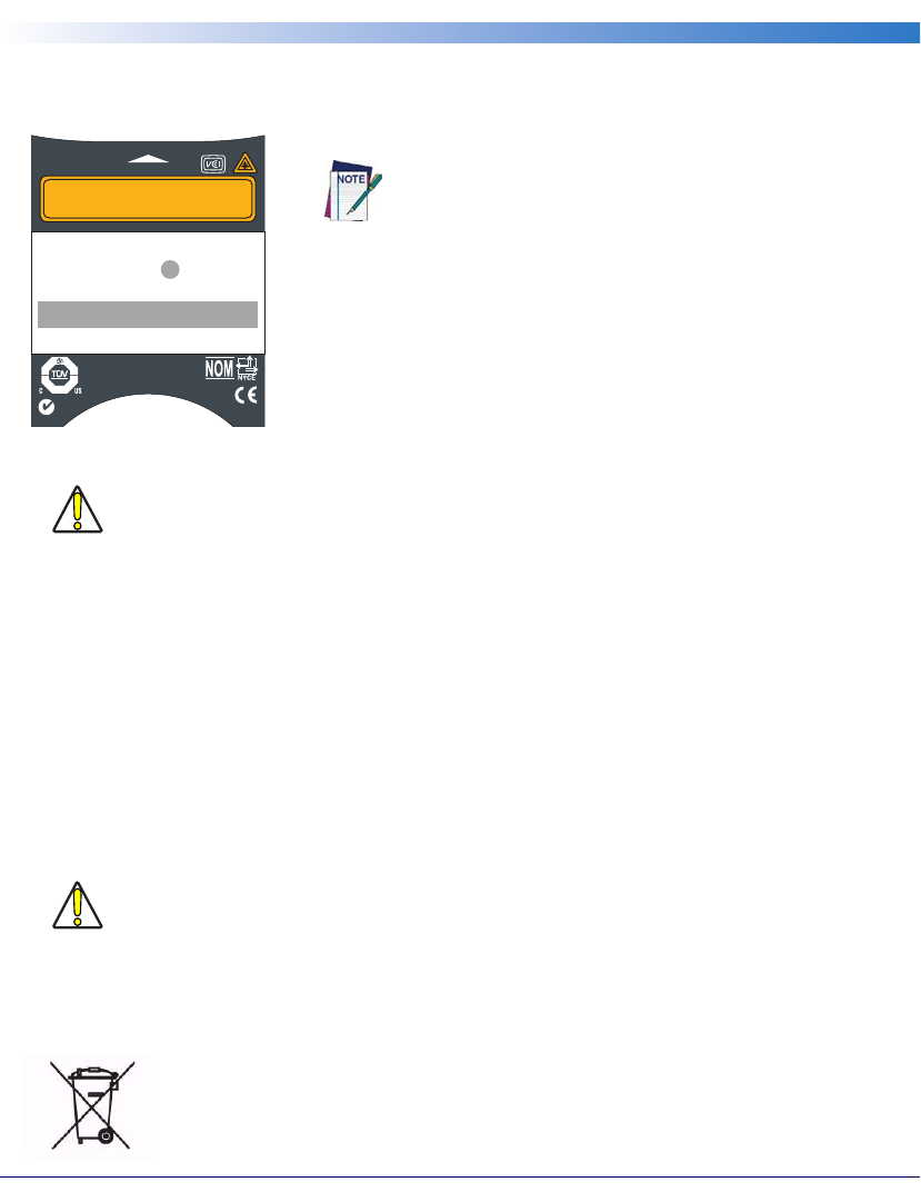
50
Falcon® 4400 Series with Windows® CE
Appendix D: Safety Information
Laser Safety Label
Figure 27. Laser Safety Label
Advisory Statement
Regulatory Statements
Radio Frequency Interference
This equipment has been tested and found to comply with the limits of a Class A digital device, pursuant to Part 15 of the FCC
Rules. These limits are designed to provide reasonable protection against harmful interference when the equipment is operated
in a commercial environment. This equipment generates, uses and can radiate radio frequency energy and, if not installed and
used in accordance with the instruction manual, may cause harmful interference to radio communications. Operation of this
equipment in a residential area is likely to cause harmful interference in which case the user will be required to correct the inter-
ference at his or her own expense.
In addition, operation of this equipment is subject to the following two conditions:
(1) This device may not cause harmful interference, and
(2) This device must accept any interference received, including interference that may cause undesired operation.
Canadian Compliance Statement
This Class A Digital apparatus complies with Canadian ICES-003.
Cet appareil numérique de la Classe A est confirme à la norme NMB-003 du Canada.
CAUTION
Use of controls, adjustments, or performance of procedures other than those specified herein
may result in hazardous visible or invisible laser light exposure.
This figure illustrates an example of a laser safety label, which is
located on the scanning pod of laser-based Falcon 4400 series
units. The label on your unit may appear different or have different
information. Please refer to your unit for specific laser safety requirements.
The Advanced Long Range Laser is rated Class 3R per EN60825-1 and
Class II per CFR 1040.
Models with the Linear Imager are rated LED Class 1 per IEC 60 825-1:2001,
only.
P
A
T
:
4
,
3
8
7
,
2
9
7
-
4
,
5
9
3
,
1
8
6
-
4
,
4
6
0
,
1
2
0
-
4
,
7
5
8
,
7
1
7
-
5
,
1
3
0
,
5
2
0
CAN: 24611032079A
N263
NRTL
Safety
tested
Production
monitored
PRODUCT SERVICE
SERIAL # FLYYDDDXXX
PRODUCT OF USA
PSC
959 Terry St.
Eugene, OR 97402
Item # 345-4201-005
EUR: CE0560RADIO: BREEZECOM
FCC: M52PCRNZZ-00
DATE OF MANUF
A
V
O
I
D
E
X
P
O
S
U
R
E
— LASER LIGHT IS EMITTED FRO
M
T
H
I
S
A
P
E
R
T
U
R
E
Complies with 21CFR and Part 15 of FCC rules.
BACKUP BATTERY: 3.1 V Lithium
Approved RLAN Module inside
CAUTION
Changes or modifications not expressly approved by the party responsible for FCC compliance
could void the user's authority to operate this equipment.
For information about the disposal of Waste Electrical and Electronic Equipment (WEEE),
please refer to the PSC website at www.psc.com.

Quick Reference Guide 51
Appendix E: Laser Safety
International Caution Statements for CLASS
1
1
, 2
2
, 3R
3
, II
4
, and IIA
5
Laser Devices
English
PSC scanners are certified in the U.S. to conform to the requirements of DHHS/CDRH 21CFR Subchapter J and
to the requirements of IEC/EN 60825-1:1998-2001.
Class 1, 2, 3R, Class II, and IIA products are not considered to be hazardous. The scanner contains internally a Vis-
ible Laser Diode (VLD) whose emissions do not exceed the maximum limits as set forth in the above regulations.
The scanner is designed so that there is no human access to harmful laser light during normal operation, user main-
tenance or during prescribed service operations.
CAUTION
If the scan pattern is a single dot when depressing the trigger, discontinue operation and return the scanner to PSC.
CAUTION
Do not attempt to open or otherwise service any components in the optics cavity. Opening or servicing any part of
the optics cavity by unauthorized personnel may violate laser safety regulations. The optics system is a factory only
repair item.
CAUTION
Use of optical systems with the scanner will increase eye hazard. Optical instruments include binoculars, micro-
scopes and magnifying glasses. This does not include eye glasses worn by the user.
French
Ce scanneurs du PSC sont certifié conforme à la norme DHHS/CDRH 21CFR sous-chapitre J et à la norme IEC/
EN 60825-1:1998-2001.
Les produits de class 1, 2, 3R, class II, et de IIA ne sont pas considérés dangereux. Le scanneur contient une diode
laser visible (VLD) dont les émissions ne dépassent pas les limites prescrites dans les normes précitées. Le scanneur
est conçu de façon à ce qu’il ne soit pas possible d’accéder à la lumière laser pendant l’utilisation normale, l’entretien
par l’utilisateur et les fonctions de maintenance prescrites.
ATTENTION
Si, quand la fonction de balayage est lancée, le diagramme de balayage est constitué d’un seul point, cesser d’utiliser
le scanneur et le retourner à PSC.
ATTENTION
Ne pas essayer d’ouvrir ou de réparer les composants de la cavité optique. L’ouverture de la cavité optique ou la rép-
aration de ses composants par une personne non qualifiée peut entraîner le non-respect des règles de sécurité rela-
tives au laser. Le système optique ne peut être réparé qu’en usine.
1. Class 1 applies to IEC/EN STD (Europe).
2. Class 2 applies to IEC/EN STD (Europe).
3. Class 3R applies to the Falcon 44xx using ALR (Advanced Long Range) Laser, only.
4. Class II applies to CDRH STD (US/Canada).
5. Class IIA applies to CDRH STD (US/Canada).

Appendix E: Laser Safety
52
Falcon® 4400 Series with Windows® CE
ATTENTION
L’utilisation d’instruments optiques avec le scanneur augmente le danger pour les yeux. Les instruments optiques
comprennent les jumelles, les microscopes et les verres grossissants. Ils ne comprennent pas les lunettes portées par
l’utilisateur.
German
Dieser Scanner ist den in den Vereinigten Staaten geltenden Vorschriften des DHHS/CDRH 21 CFR Subchapter J
und den Vorschriften der IEC/EN 60825-1:1998-2001 entsprechend bescheinigt.
Produkte der Klasse 1, 2, 3R, Klasse II oder der IIA sind als ungefährlich eingestuft. Im Inneren des Scanners befin-
det sich eine VLD (Visible Laser Diode), deren Ausstrahlung die in den oben genannten Vorschriften angeführten
Höchstgrenzen nicht überschreitet. Die Konstruktion des Scanners garantiert, daß bei normalem Betrieb, bei War-
tung durch den Benutzer oder im Laufe planmäßiger Wartungsarbeiten kein Zugang zu schädlichem Laserlicht
besteht.
VORSICHT:
Sollte das Abtastbild bei gedrücktem Auslöser aus einem einzigen Punkt bestehen, muß der Betrieb eingestellt und
der Scanner an PSC zurückgesendet werden.
VORSICHT:
Unter keinen Umständen darf versucht werden, die Komponenten im Optikhohlraum zu öffnen oder auf
irgendwelche andere Weise zu warten. Das Öffnen bzw. Warten der Komponenten im Optikhohlraum durch
unbefugtes Personal verstößt gegen die Laser-Sicherheitsbestimmungen. Das Optiksystem darf nur werkseitig rep-
ariert werden.
VORSICHT:
Die Verwendung von Optiksystemen mit diesem Scanner erhöht die Gefahr einer Augenbeschädigung. Zu optis-
chen Instrumenten gehören unter anderem Ferngläser, Mikroskope und Vergrößerungsgläser, nicht aber die von
Benutzern getragenen Brillen.
Italian
È stato certificato che questo scanner si conforma ai requisiti della sezione J della normativa DHHS/CDRH
21CFR, e anche ai requisiti di IEC/EN 60825-1:1998-2001.
I prodotti di Classe 1, 2, 3R, Classe II, o IIA non sono considerati pericolosi. Lo scanner contiene al suo interno un
Visible Laser Diode (VLD), diodo laser visibile, le cui emissioni non eccedono i limiti stabiliti dalle normative sun-
nominate. Lo scanner è progettato in modo che non ci sia alcun accesso alla luce dannosa del laser nel corso di uso
normale, di manutenzione da parte dell’utente o durante la manutenzione periodica stabilita.
ATTENZIONE
Se, quando si preme l’azionamento, il pattern di scansione è un punto singolo, interrompere l’operazione e ripor-
tare lo scanner a PSC .
ATTENZIONE
Non tentare di accedere allo scomparto contenete i componenti ottici o di farne la manutenzione. L’apertura dello
scomparto, o la manutenzione di qualsiasi parte ottica da parte di personale non autorizzato, potrebbe violare le
norme della sicurezza. Il sistema ottico può essere riparato solamente alla fabbrica.
ATTENZIONE
L’uso di strumenti ottici assieme allo scanner può aumentare il pericolo di danno agli occhi. Tali strumenti ottici
includono cannocchiali, microscopi e lenti di ingrandimento. Essi non includono gli occhiali indossati dall’utente.

International Caution Statements for CLASS 1, 2, 3R, II, and IIA Laser Devices
Quick Reference Guide 53
Danish
Denne scanner opfylder de amerikanske krav stillet i "DHHS/CDRH 21CFR Subchapter J" og opfylder også de
krav, der stilles i IEC/EN 60825-1:1998-2001.
Klasse 1, 2, 3R, klasse II eller klasse IIA produkter anses for at være sikre. Scanneren indeholder en Visible Laser
Diode (VLD), der ikke overskrider maksimumgrænserne, som beskrevet i ovenstående reglement. Scanneren er
konstrueret, så der ikke er nogen menneskelig kontakt medskadelige niveauer af laserbestråling under normal brug,
normal vedligeholdelse eller under foreskrevet servicering.
ADVARSEL
Hvis scanningmønsteret er et enkelt punkt, når triggeren indtrykkes, skal betjening ophøre og scanneren returneres
til PSC.
ADVARSEL
Forsøg ikke at åbne eller reparere komponenter i det optiske hulrum. Uautoriseret åbning eller reparation af
komponenter i det optiske hulrum kan være en overtrædelse af lasersikkerhedsregulativer. Det optiske system må
udelukkende repareres as PSC.
ADVARSEL
Anvendelse af optiske systemer med scanneren øger risikoen for øjenskader. Optiske instruments omfatter kik-
kerter, mikroskoper og lupper. Det omfatter ikke anvendelse af almindelige briller.
Dutch
Deze scanner is in de V.S. goedgekeurd en voldoet aan de vereisten van DHHS/CDRH 21CFR Subchapter J een
aan de vereisten van IEC/EN 60825-1:1998-2001.
Producten van klasse 1 ,2, 3R, klasse II en IIA worden niet geacht gevaarlijk te zijn.
De scanner bevat een inwendige Visible Laser Diode (VLD) waarvan de emissies de maximumgrenzen van boven-
staande reglementen niet overschrijden.
De scanner is zo ontworpen dat men bij normaal gebruik, onderhoud of tijdens het uitvoeren van de voorge-
schreven onderhoudswerkzaamheden niet aan schadelijke niveaus wordt blootgesteld.
WAARSCHUWING
Als het scanpatroon bij het overhalen van de trekker een enkele stip is, stop dan onmiddellijk en stuur de scanner
terug naar PSC.
WAARSCHUWING
Probeer niet om onderdelen in de opticaruimte te openen of er onderhoud aan uit te voeren. Het openen of onder-
houden van delen in de opticaruimte door onbevoegd personeel kan een inbreuk vormen op de laserveiligheidsre-
glementen. Het opticasysteem mag alleen in de fabriek worden gerepareerd.
WAARSCHUWING
Het gebruik van optische systemen samen met de scanner vergroot het risico voor de ogen. Optische instrumenten
zijn onder andere binoculairs, microscopen en vergrootglazen, maar niet de bril die de gebruiker draagt.
Swedish
Denna scanner uppfyller de amerikanska kraven DHHS/CDRH 21CFR Subchapter J samt kraven i IEC/EN
60825-1:1998-2001.
Produkter i Klass 1, 2, 3R, Klass II och IIA anses ej farliga. Scannern är utrustad med en intern, synlig laserdiod
(Visible Laser Diode - VLD) vars emission inte överstiger max. värdena i ova stående säkerhetsföreskrifter. Scannern
har konstruerats så att personer vid normal användning, bruksunderhåll och föreskriven service inte utsätts för
skadlig laserstrålning.
VAR FÖRSIKTIG
Om scanningsmönstret är en enda punkt när du trycker på avtryckaren, ska du avbryta användningen och ta scan-
nerna tillbaka till PSC.

Appendix E: Laser Safety
54
Falcon® 4400 Series with Windows® CE
VAR FÖRSIKTIG
Försök inte öppna eller reparera komponenter i den optiska kamaren. Om icke auktoriserad personal öppnar eller
reparerar delar i den optiska kammaren, kan detta strida mot säkerhetsföreskrifterna för laserutrustning. Det
optiska systemet får endast repareras på fabriken.
VAR FÖRSIKTIG
Användning av optiska system med scannern ökar risken för ögoskada. Optiska instrument inkluderar kikare, mik-
roskop och förstoingsglas, men inte användarens glasögon.
Finnish
Tämä tutkain on hyväksytty Yhdysvalloissa vastaamaan DHHS/CDRH 21CFR Subchapter J luokka 60825-
1:1998-2001 IEC/EN-vaatimuksia.
Luokka 1, 2, 3R, Luokka II tai IIAtuotteiden ei katsota olevan vaarallisia. Tutkain sisältää sisäisen näkyvän laserdio-
din (Visible Laser Diode (VLD), jonka päästöt eivät ylitä yllä olevien säädösten asettamia maksimirajoja. Tutkain
on suunniteltu siten, etteivät ihmiset altistu vaaralliselle lasersäteilylle normaalikäytön, käyttäjän suorittaman huol-
lon tai ohjeiden mukaisten huoltotoimenpiteiden aikana.
VAROITUS
Jos skannauskuva on yksittäinen piste laukaisinta painettaessa, keskeytä käyttö ja palauta tutkain PSC:lle.
VAROITUS
Älä yritä avata tai muuten huoltaa mitään rakenneosia optisessa osassa. Valtuuttamattoman henkilöstön suoritta-
man optisen osan avauksen tai huoltotoimen voidaan katsoa olevan rikkomus lasersuojaohjeita vastaan. Optisen
järjestelmän saa korjata ainoastaan tehtaalla.
VAROITUS
Mikäli optisia järjestelmiä käytetään tutkainmen kanssa, silmille aiheutuva vaara lisääntyy. Optiset kojeet käsittävät
kiikarit, mikroskoopit ja suurennuslasit. Käyttäjän silmälasit eivät kuulu tähän ryhmään.
Norwegian
Denne skanneren er godkjent i USA i samsvar med retningslinjene for DHHS/CDRH 21CFR, avsnitt J, og til
IEC/EN 60825-1:1998-2001.
Produkter i klasse 1 2, 3R, klasse II eller IIA ansees ikke som helsefarlige. Skanneren inneholder en innvendig, syn-
lig laserdiode (VLD, Visible Laser Diode), som ikke overskrider maksimalgrensene som er fastsatt i retningslinjene
ovenfor. Skanneren er konstruert, slik at personer ikke utsettes for farlige doser med laserstråler ved normal drift,
brukers vedlikehold eller ved foreskrevet service.
OBS!
Hvis skanningsmønsteret består av én enkel prikk når utløseren trykkes inn, skal driften stanses, og skanneren settes
tilbake til PSC.
OBS!
Prøv ikke å åpne eller på noen måte utføre service på noen av delene i det optiske kammeret. Ved å åpne eller utføre
service på noen av delene i det optiske kammeret av uautorisert personell, kan krenke forskriftene for lasersikkerhet.
Optikksystemet skal bare repareres på fabrikken.
OBS!
Bruk av optiske systemer med skanneren kan innebære høyere fare for øynene. Optiske instrumenter innbefatter,
kikkerter, mikroskop og forstørrelsesglass. Dette omfatter ikke briller som brukeren har
på seg.

International Caution Statements for CLASS 1, 2, 3R, II, and IIA Laser Devices
Quick Reference Guide 55
Portuguese
Este scanner foi certificado nos EUA para atender os requisitos do subcapítulo J do DHHS/CDRH 21 CFR e os
requisitos do IEC/EN 60825-1:1998-2001.
Os produtos da Classe 1, 2, 3R, Classe II ou IIA não são considerados perigosos. O scanner contém internamente
um Diodo de Laser Visível (VLD - Visible Laser Diode) cujas emissões não ultrapassam os limites definidos nos
regulamentos mencionados acima. O scanner foi projetado de maneira que não exista acesso humano à luz de laser
nociva durante a operação normal, manutenção pelo usuário ou durante as operações recomendadas de serviço.
CUIDADO
Se ao pressionar o gatilho a luz do laser for um único ponto, interrompa a operação e devolva o scanner à PSC.
CUIDADO
Não tente abrir ou consertar qualquer componente da cavidade óptica. A abertura ou manutenção de qualquer peça
da cavidade óptica por pessoal não autorizado pode infringir os regulamentos de segurança do laser. O sistema
óptico só deve ser reparado na fábrica.
CUIDADO
O uso de instrumentos ópticos com o scanner aumenta o risco para a visão. Incluem-se entre os instrumentos ópti-
cos os binóculos, microscópios e lentes de aumento. Não se incluem os óculos usados pelo usuário.
Spanish
Este escáner está certificado en los EE.UU. porque reúne los requisitos DHHS/CDRH 21CFR Sección J y los req-
uisitos de IEC/EN 60825-1:1998-2001.
Los productos de Clase 1, 2, 3R, Clase II, o IIA no se consideran como peligrosos. El escáner tiene en su interior un
Diodo Láser Visible (VLD) cuyas emisiones no exceden los límites máximos fijados en los reglamentos menciona-
dos anteriormente. El escáner está diseñado de modo que las personas no tengan acceso a la luz láser peligrosa
durante la operación normal, el mantenimiento por parte del usuario o durante las operaciones de servicio prescri-
tas.
PRECAUCIÓN
Si al oprimir el interruptor, el patrón de exploración es un solo punto, discontinúe el uso y devuelva el escáner a
PSC.
PRECAUCIÓN
No intente abrir o de ninguna manera dar servicio a ninguno de los componentes del receptáculo óptico. Abrir o
dar servicio a las piezas del receptáculo óptico por parte del personal no autorizado podría ser una violación a los
reglamentos de seguridad. El sistema óptico se puede reparar en la fábrica solamente.
PRECAUCIÓN
El uso de sistemas ópticos con el escáner aumentará el riesgo de daños oculares. Los instrumentos ópticos incluyen
binoculares, microscopios y lupas. Esto no incluye los lentes recetados usados por el usuario.
Appendix E: Laser Safety
56
Falcon® 4400 Series with Windows® CE
Chinese
International Caution Statements for CLASS 1, 2, 3R, II, and IIA Laser Devices
Quick Reference Guide 57
Japanese

Appendix E: Laser Safety
58
Falcon® 4400 Series with Windows® CE
NOTES

International Caution Statements for CLASS 1, 2, 3R, II, and IIA Laser Devices
Quick Reference Guide 59
NOTES

Appendix E: Laser Safety
60
Falcon® 4400 Series with Windows® CE
NOTES

DECLARATION OF CONFORMITY
PSC hereby declares that the Equipment specified below has been tested
and found compliant to the following Directives and Standards:
Brad West
Vice President
Quality and Process Management
PSC, Inc.
959 Terry Street
Eugene, OR 97402
U.S.A.
Peter Lomax
Vice President
Europe, Middle East & Africa
PSC Bar Code Ltd.
Axis 3, Rhodes Way
Watford
Hertfordshire WD24 4TR
UK
Directives: EMC 89/336/EEC, Low Voltage 73/23/EEC, R&TTE 1999/5/EC
Standards
Equipment: EN 55022-B:2001; CISPR 22:2001; EN 55024:2001; EN 60825-1:2001;
EN60950:2000
Power Sup-
plies: EN 55014-1/2:1997, EN60950, EN 61558-1/2:1997+A1
Radios: EN 300-328-1 and -2:2000, EN 301.489.1/17:2000, EN60950:1992+A4
Equipment
Type: Portable Data Terminal Equipment
Product: Falcon 44xx, Four-Slot Battery Charger, Single/Four-Slot Dock Stations
Declaration of Conformity with Regard to the R&TTE Directive 1999/5/EC
English:
Nederlands:
Suoma-
lainen:
Français:
Deutsch:
Italiano:
Dansk:
Português:
Español:
Svenska:
Norsk:
lslenska:
This equipment is in compliance with the essential requirements & other relevant provisions of Directive 1999/5/EC.
Deze apparatuur voldoet aan de essentiële vereisten en andere relevante voorzieningen van EU-richtlijn 1999/5/EC.
Tämä laite noudattaa direktiivin 1999/5/EC keskeisiä vaatimuksia ja sen muita olennaisia määräyksiä.
Cet équipement répond aux exigences et provisions de la Directive 1999/5/EC.
Diese Geräte entsprechen den Anforderungen und anderen relevanten Bestimmungen der Richtlinie 1999/5/EC.
Questa apparecchiatura rispetta i requisiti essenziali e le altre clausole rilevanti della Direttiva 1999/5/CE.
Dette utstyret er i samsvar med de grunnleggende kravene og andre relevante forskrifter i 1999/5/EC-direktivet.
Este equipamento está de acordo com os requisitos essenciais e outras provisões relevantes da Diretiva 1999/5/
EC.
Este equipo cumple con los requisitos esenciales y otras provisiones relevantes de la Directiva 1999/5/EC.
Denna utrustning uppfyller de väsentliga kraven och andra relevanta förordningar i Direktiv 1999/5/EC.
Dette utstyret er i samsvar med de grunnleggende krav og andre relevante bestemmelser i EU-direktiv 1999/5/EF
Þetta taeki er samkvaemnt grunnkröfum og öðrum viðeigandi ákvaðum Tilskipunar 1999/5/CE.

Asia Pacific
PSC Hong Kong
Hong Kong
Telephone: [852]-2-584-6210
Fax: [852]-2-521-0291
Australia
PSC Asia Pacific Pty Ltd.
North Ryde, Australia
Telephone: [61] (2) 9870 3200
Fax: [61] (2) 9878 8688
France and Benelux
PSC S.A.R.L.
LES ULIS Cedex, France
Telephone: [33].01.64.86.71.00
Fax: [33].01.64 46.72.44
Germany
PSC GmbH
Darmstadt, Germany
Telephone: 49 (0) 61 51/93 58-0
Fax: 49 (0) 61 51/93 58 58
Italy
PSC S.p.A.
Vimercate (MI), Italy
Telephone: [39] (0) 39/62903.1
Fax: [39] (0) 39/6859496
Japan
PSC Japan K.K.
Shinagawa, Tokyo, Japan
Telephone: 81 (0)3 3491 6761
Fax: 81 (0)3 3491 6656
Latin America
PSC S.A., INC.
Miami, Florida, USA
Telephone: (305) 591-3222
Fax: (305) 591-3007
Spain and Portugal
PSC
Madrid, Spain
Telephone: 34 91 746 28 60
Fax: 34 91 742 35 33
United Kingdom
PSC Bar Code Ltd.
Watford, England
Telephone: 44 (0) 1923 809500
Fax: 44 (0) 1923 809 505
www.psc.com
PSC Inc.
959 Terry Street
Eugene, OR
Telephone: (541) 683-5700
Fax: (541) 345-7140
©2007 PSC INC. R44-2490 (Rev J) 2/07