Datalogic S r l 0020 Star Module Plus 910MHz User Manual StarModulePlus910 1 3
Datalogic ADC S.r.l. Star Module Plus 910MHz StarModulePlus910 1 3
Contents
- 1. Usermanual part 1
- 2. Usermanual part 2
- 3. Integration Guide
Integration Guide

StarModulePlus910_1_3.d
oc Revision: 1.3 19/05/2010 Confidential page 1 of 1
DATALOGIC PROPRIETARY INFORMATIONS
STAR-Module Plus 910
Preliminary
Rev 1.3
Integration Guide
Author:
Luciano Ruggiero
Pier Giorgio Peruzzi

SmallSTAR-Module 910
StarModulePlus910_1_3.d
oc
Preliminary
Confidential page 2 of 2
DATALOGIC PROPRIETARY INFORMATIONS
Document History
Rev 1.3 FW release 119 : New Radio Low Cost Plus version added
Rev 1.2 FW release 118: Ddttl improvement, TX routine without byte stuffing
Rev 1.1 FW release 117R: Calibration address bug fixed, CD improvement
Rev 1.0 FW release 116F
Introduction………………………………………………………………………………….2
Pinout………………………………………………………………………………………….3
Electrical characteristics……………………………….……………………………………3
RF chracteristics…..…………………………………………………………………………4
Timings…………………………………………………………………………………………4
Block diagram…………………………………………………………………………………4
Basic module states………………………………………………………………………….5
Introduction
The STAR-Module 910 SLC is an FSK RF half-duplex transceiver working at 910 MHz.
Its main features are:
• UART baud rate of 38400 8 n 1bps
• Default RF baud of 36864bps Manchester encoded
• Extended 5.5 to 3.1 V power supply
• Temperature range –20°C / +55°C
• High RF frequencies precision, due to utilization of a PLL synthesizer
• Factory calibration parameters saved on write protected flash block
• Factory pre-loaded unique 32 bit address for each module
• RF front-end with SAW filter for high out-of-band noise rejection and low spurius level emission
• On-board temperature sensor for compensation of frequency drift
• Bootloader for in circuit firmware upgrate
• Sub-milliampere sleep mode
• On-board EEPROM for configuration parameters
SmallSTAR-Module 910
StarModulePlus910_1_3.d
oc
Preliminary
Confidential page 3 of 3
DATALOGIC PROPRIETARY INFORMATIONS
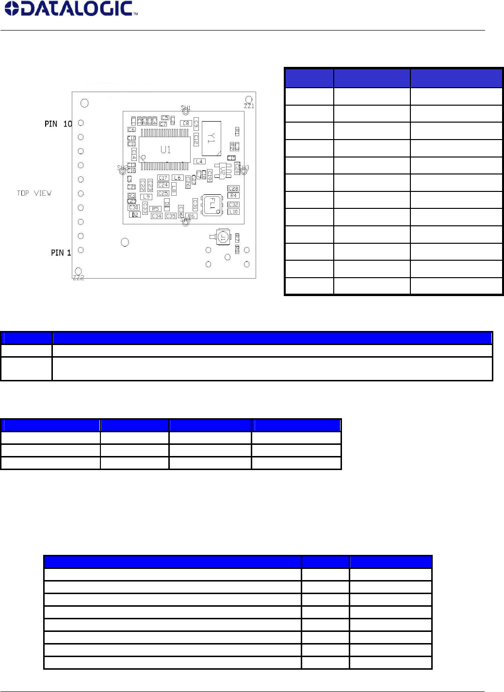
Pinout
IDLE/RX Function
HIGH Sleep
LOW Rx mode
Receive data on TX_DATA, CD# asserted means RF channel is busy
Electrical characteristics
Description @ 3.3 V @ 5 Unit
TX mode current 18 31 mA
RX mode current 16 21 mA
IDLE mode current 32 52 uA
RF characteristics
Description Typ Unit
TX/RX center frequency 910 MHz
FSK modulation frequency shift +/- 75 kHz
RX bandwidth 300 kHz
Output power (50 Ohm load) -2.5 dBm
RX Sensitivity (BER < 5% @36864 baud) -106 dBm
CD# threshold -76 dBm
RF in/out impedance 50 Ohm
Frequency drift from –25 to +55°C +/- 50 ppm
RF CONNECTOR - J1
GROUND - 10
RESET_ Input 9
IDLE Input 8
Vdc (3.1 to 5.5 V)
- 7
GROUND - 6
not connected - 5
RX_DATA Output 4
CD# (active low) Output 3
TX_DATA Input 2
GROUND - 1
Description Direction Numbe
r
SmallSTAR-Module 910
StarModulePlus910_1_3.d
oc
Preliminary
Confidential page 4 of 4
DATALOGIC PROPRIETARY INFORMATIONS
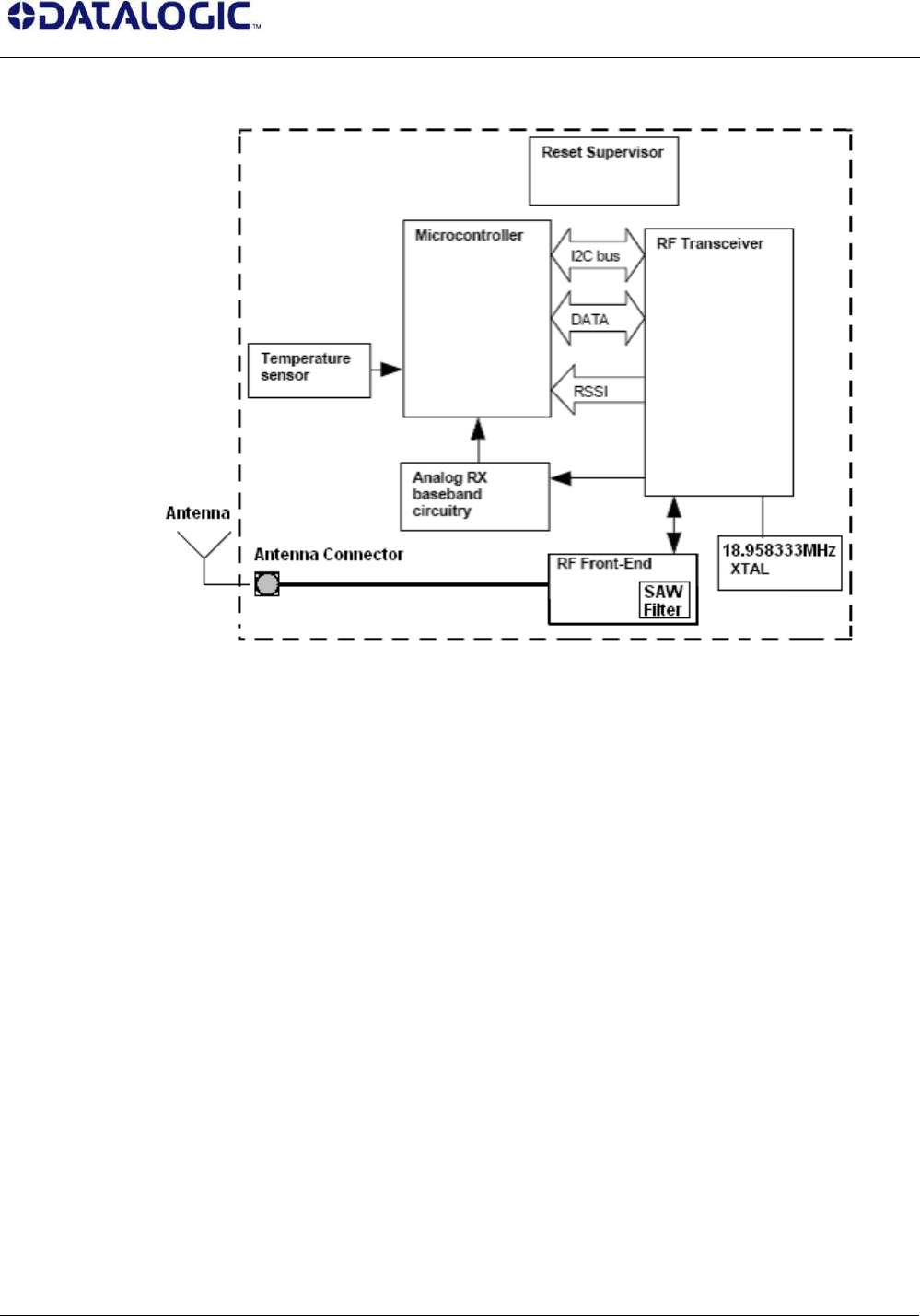
Block diagram
Blocks description:
• Reset supervisor: the microcontroller is reset when power supply falls below 3V
• Temperature sensor: 10kOhm NTC
• Microcontroller: Atmel ATMega8L with RISC AVR core, 8kB Flash, 1kB SRAM, 512 B EEPROM,
ADC, UART, I2C controller, 8MHz internal clock oscillator
• RF Transceiver: Infineon TDA5252 with PLL synthesizer (reference oscillator 18.958333MHz)
• Analog RX baseband circuitry: processing of analog signal from transceiver demodulator to uC
ADC
• RF Front End: SAW filter, PIN-diode based RX-TX switch
SmallSTAR-Module 910
StarModulePlus910_1_3.d
oc
Preliminary
Confidential page 5 of 5
DATALOGIC PROPRIETARY INFORMATIONS
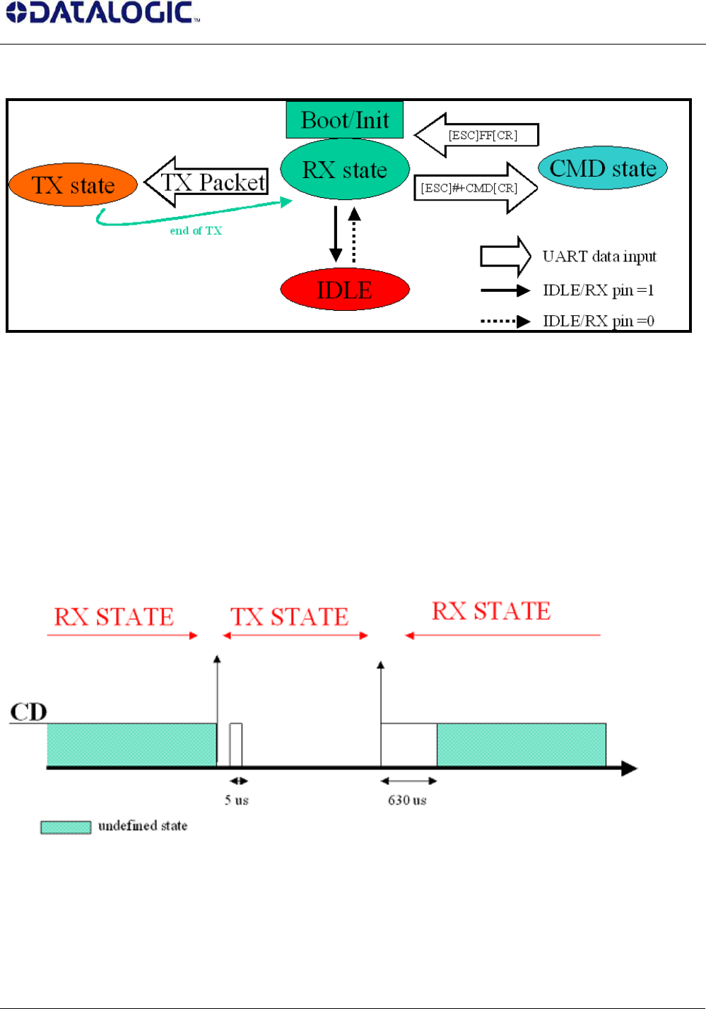
Basic module states
Different states explanation:
• IDLE: this state is entered when pin IDLE is set High. Power consumption is lowered to less than 100
uA. In idle state the radio module is unable to receive or transmit data packets.
• TX: RF power amplifier is active. This state can be entered from RX mode, sending to the module a
formatted TX packet. Tx mode can’t be hold active more than the maximum data packet (about 20
mS).
• RX:receiver is active. Data is sent out from RX_DATA pin and CD is set depending from presence or
not of RF carrier.
• COMMAND: the module exits from normal functioning and is able to receive configuration
commands from host. This state can be entered from RX mode, sending to the module the escape
string [ESC]#+CMD[CR] @ 38400, 8, N, 1. To exit this state, the appropriate command must be sent.
Fig. 1
RX mode
Received RF signal is down-converted to baseband, demodulated and converted to a bit stream presented
on TX_DATA pin. Also CD# is driven, asserting presence or lack of carrier in the RF channel as in Fig 1.

SmallSTAR-Module 910
StarModulePlus910_1_3.d
oc
Preliminary
Confidential page 6 of 6
DATALOGIC PROPRIETARY INFORMATIONS
Absence of RF: high level.
Presence of RF: low level.
The RF down conversion starts with the reception of the 0xB2 (old protocol) or 0x96 (new protocol) byte,
followed by the packet length byte. According to this value the conversion goes on receiving length number
bytes plus the two CRCs.
Thus the byte stream presented on TX_DATA (output) UART starts with 0xFF, 0xB2 or 0x96, the packet
length byte and so on sending the number of length byte to complete the packet reception plus the CRCs
bytes.
Active blocks are:
Receiver part of transceiver
ADC conversion of RSSI signal
DSP of the analog demodulated signal in order to decide the best RX frequency out of the 2 available
Analog signal conditioning block, prior to ADC conversion
ADC conversion of temperature indication and compensation
UART to receive command strings from the host @38400, N, 8, 1 on pin Data In.
The reception of the enter test string [ESC]#+CMD[CR] causes the exit from RX mode and the entering of
CMD mode, while the reception of the TX command [STX] [DATA] causes the exit from RX mode and the
entering in TX mode transmitting data.
Enter Test: [ESC]#+CMD[CR] to enter in CMD mode
TX Packet: [STX] [DATA] to transmit [DATA]
TX mode
Frame sent by the host on pin RX_DATA is up-converted to RF, modulated and power-amplified.
During TX mode CD# line is shown in Fig. 2 during the TX state.
Active blocks are:
Transmitter part of transceiver
Power amplifier
TX Packet Formatting
Transmission starts only sending a data packet with a specific data format and without delay between one
byte to the next one of the data packet. Transmission ends when is transmitted the last byte received from
the host (max 96 bytes). At least transmision ends as soon as sent the 96th byte from the first byte of the
packet.
The [DATA] frame to be transmitted has to be formatted as follows :
The first byte must be [STX] (0x02) : this is the TX key char. As soon as received th STX byte the radio
module start to send a 12 bytes preamble. The preamble is followed from the bytes of the data packet up to
the last one.
The second byte must be the SOF (start of frame byte depending from the protocol used. Now are supported
0xB2 or 0x96 only)
The third byte must be the frame length (from length byte itself to the CRC field excluded).
Follows all other bytes of the packet to be transmitted.
Example:
to transmit the data packet : “0x25 0x10 0x25 0x40 0x11” – 5 bytes,
the packet to be sent to the radio has to be :
[0x02] [0x96] [0x06] [0x25] [0x10] [0x25] [0x40] [0x11] [CRC1] [CRC2].
Number of TX bytes sent = length (0x06) + 3. [STX], the TX key char, is not sent.
The transmitted preamble is 12 bytes length.
SmallSTAR-Module 910
StarModulePlus910_1_3.d
oc
Preliminary
Confidential page 7 of 7
DATALOGIC PROPRIETARY INFORMATIONS
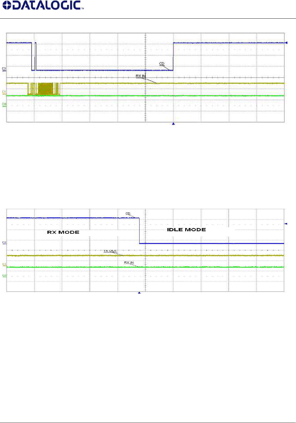
The module returns in RX state after transmitting all the bytes of the packet.
Fig. 2
IDLE mode
In order to maximize battery duration on portable devices a low-consumption state is used.
In this state with IDLE/RX_ pin asserted, all hardware blocks swith to power-down mode or switched off.
To wake up the module, the host must deasserted IDLE/RX pin (Set RTS). In IDLE mode CD# has low level
(shown in fig. 3).
Fig. 3
COMMAND mode
When the host puts the module in RX mode and then sends the escape string [ESC]#+CMD[CR],
COMMAND mode is entered.
To confirm COMMAND mode, STAR-Module answers to the host the string [STX][CR] using TX_DATA pin.
In this state normal functioning is disabled, but it is possible to send configuration commands to the module,
in order to change the settings loaded on its configuration EEPROM.
Command must be sent using RX_DATA pin @38400, N, 8, 1 in the form: [ESC]xxxx[CR].
While answers from the module are in the form: [STX]xxx[CR].
If an incorrect command is sent, the answer is: [STX][NAK][CR].
In Command mode CD# has low level.
The state is exited using the exit command: [ESC]FF[CR] causing the reset of the module and activating the
new configuration saved on EEPROM.
NOTE: commands are case sensitive.

SmallSTAR-Module 910
StarModulePlus910_1_3.d
oc
Preliminary
Confidential page 8 of 8
DATALOGIC PROPRIETARY INFORMATIONS
RF interface
StarModulePlus910 has 50 Ohm impedance on RF out in TX and RX mode, therefore impedance
matching is required for antenna system of host.
Care must be taken for the proximity of conductive materials or the user’s hand that will cause a
mismatch of the antenna, decreasing the transceiver RF characteristics.
Moreover, care must be taken to ensure that the host system doesn’t have spurious emissions in the
range 910MHz+/-200kHz, that could cripple receiver sensitivity: it is advised to put a ground plane
under the RF module and to filter the power supply.
Noisy parts, like system buses, must be shielded in order not to irradiate spurious fields.
This device complies with Part 15 of the FCC Rules. Operation is subject to the following two
conditions:
1) This device may not cause harmful interference, and
2) This device must accept any interference received, including interference that may cause
undesired operation.
Any change or modification to the product not expressly approved by Datalogic Scanning Group
S.r.l. could void the user's authority to operate the device.