Datalogic S r l 0020 DL-SKORPIO User Manual b Datalogic Skorpio Master
Datalogic ADC S.r.l. DL-SKORPIO b Datalogic Skorpio Master
Contents
- 1. Usermanual part 1
- 2. Usermanual part 2
- 3. Integration Guide
Usermanual part 2
USE AND FUNCTIONING
21
3
3.6 DATA CAPTURE CONFIGURATION
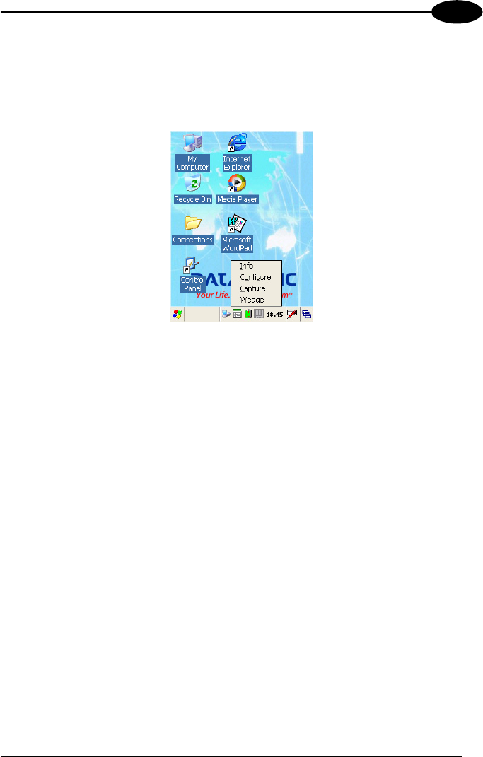
From the Taskbar, tap the "Data Capture" icon to open a drop–down menu. Data
Capture can also be accessed from the Control Panel.
By selecting the Info item from this drop-down menu you can access information
about the Scanner and the Software; the Configure item opens the configuration
applet (Data Capture Configuration Window), while Capture accesses the data
capture applet (Data Capture Window), which enables code reading.
The last menu item (Wedge) enables Wedge Emulation.
3.6.1 Configure
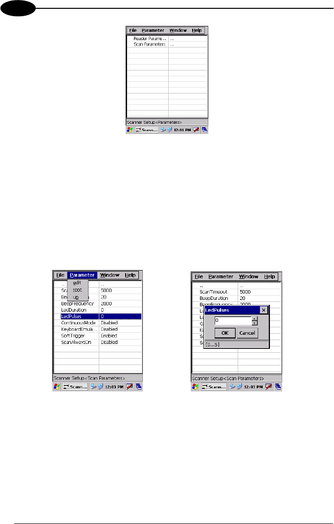
The Configuration applet contains the barcode scanning configuration parameters in
a directory tree structure. The available barcode parameters are divided into two
groups: Reader Parameters and Scan Parameters.
The Reader Parameters depend on the type of scanner module installed on the
mobile computer and allow barcode configuration (i.e. enable/disable Code 39, check
digit control, etc.).
The Scan Parameters are common to all scanner modules and allow control of the
scanning device (i.e. LED control, laser timeout, etc.).
Each Data Capture screen window corresponds to a branch of the tree, and the
name of the current branch is displayed at the bottom of each screen window.
DATALOGIC SKORPIO™
22
3
Data Capture Configuration Window
The screen format shows two columns where the left column indicates branches or
parameters. Branches have three dots in the right column (...). You can navigate
through the tree structure using the stylus or keyboard arrows directly on the item
field or from the menu.
Parameters have their corresponding current values in the right column. You can edit
parameter values using the stylus or keyboard arrows directly on the item field or
from the menu. To change a value for example, select the line of the value to be
changed, choose Edit from the Parameter Menu then choose a new value from the
values listed in the box (see following figures).
Selecting Data Capture Setup Parameters
Alternatively using the stylus, you can tap once directly on the value on the right
column; continue tapping until the desired value is reached.
To activate a new configuration select the File ->Save Menu to send the new
configuration to the barcode decoding software and save the new configuration. This
will save the configuration to non-volatile memory preventing loss at the next system
reset.

USE AND FUNCTIONING
23
3
Reader Parameters
The barcode reading parameters and values are dependent upon the type of scanner
module mounted in your mobile computer. For a detailed list of parameters and of
their configuration procedures, please refer to the SDK Help file on the CD.
Scan Parameters
The Scan Parameters are common to all scanner modules and allow control of the
scanning device. The Scan parameters are described as follows:
ScanTimeout: the maximum time, in milliseconds, during which the scanner remains
on without decoding any barcode.
GoodReadSound: is the filename of a wav file played when the scanner reads a
code.
LedDuration: the length of the good-read led pulse, in milliseconds.
LedPulses: the number of times the good-read led pulse is emitted when the
scanner reads a code.
Green Spot Duration: determines the duration (measured in milliseconds) of the
green spot feedback, which provides a ”good read” green dot directly on the code,
where the operator usually tends to be looking.
ContinuousMode: disables the effect of the ScanTimeout parameter.
KeyboardEmulation: if enabled all scanned data are transformed into keyboard
events and can therefore be displayed and saved to a file as if input from the mobile
computer keyboard.
SoftTrigger: when enabled, the laser can be turned on/off by the application
software.
ScanAlwaysOn: enables the scanner for barcode reading independently from the
application software.
NotPrintableChar: if set to "Remove", all not printable characters included in the
scanned data are deleted and the final barcode will include only printable characters.

DATALOGIC SKORPIO™
24
3
Default Settings
The following tables contain the default values for the major barcode setup
parameters, according to the type of scan engine mounted on the mobile computer.
For a complete list of parameters and of their configuration procedures, please refer
to the SDK Help file on the CD.
SCAN PARAMETERS
ScanTimeout 5000
GoodReadSound Beep.wav
LedDuration 200 mS
LedPulses 1
GreenSpotDuration 1000
ContinuousMode Disabled
KeyboardEmulation Disabled
SoftTrigger Enabled
ScanAlwaysOn Disabled
BARCODE SYMBOLOGY
SPECIFIC READER PARAMETERS
UPC A Enabled
UPC E Enabled
EAN 8 Enabled
EAN 13 Enabled
Code 39 Enabled
Code 39 Full ASCII Disabled
Code 32 Disabled
2/5: Interleaved Enabled
2/5: Industrial Disabled
2/5: Matrix Disabled
Code 128 Enabled
EAN 128 Enabled
Codabar Enabled
BARCODE SYMBOLOGY
SPECIFIC READER PARAMETERS
MSI Enabled
Plessey Disabled
Code 93 Disabled
Code 11 Disabled
USE AND FUNCTIONING
25
3
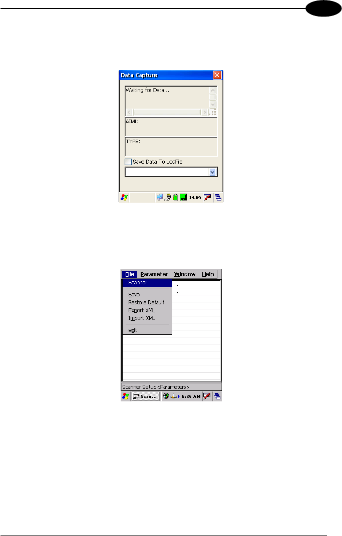
3.6.2 Capture
The Data Capture applet (Capture) enables code reading.
Data Capture Window
Data Capture can also be enabled through the Configuration applet by selecting File
->Scanner from the main menu, or by enabling the parameter Scan Always On in the
Scan Parameters branch.
Enabling the Data Capture
DATALOGIC SKORPIO™
26
3
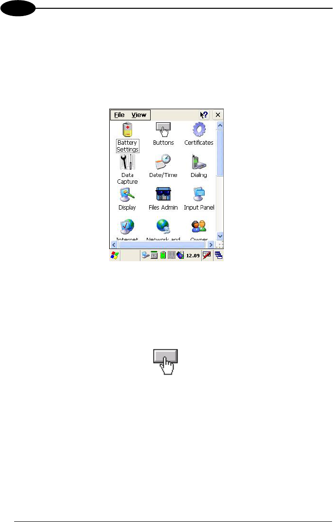
3.7 CONTROL PANEL
From the Desktop, double tap on the "Control Panel" icon to open the Windows CE
control panel main window. The Control Panel can also be launched from Start -
>Settings ->Control Panel.
APPLET programs are displayed as icons; one icon corresponds to each APPLET.
Control Panel
3.7.1 Buttons
The BUTTONS Applet allows assigning desired applications to be launched by one
of the function keys (F1, F2, F3, F4).
You can also select to wake up the terminal by the SCAN key.
USE AND FUNCTIONING
27
3
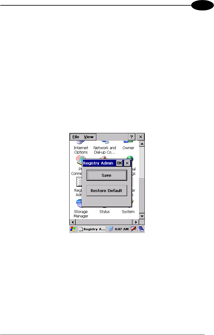
3.7.2 Registry
The REGISTRY ADMIN applet provides management of Windows CE registry.
Select the REGISTRY ADMIN applet by double tapping the Registry Admin icon.
The Registry Administration Main window appears. Two functions are available:
- Save Registry allows permanently saving the Windows configuration (example:
custom configuration of screen desktop background color, or network adapter
configuration) to non-volatile memory (SAVE button).
- Restore Default Registry allows restoring the initial factory default configuration
(Restore Default button). After restoring the factory default configuration, you
must perform a software reset.
Saving the registry to non-volatile memory guarantees the persistence of the
Windows configuration in case of battery pack replacement.
Registry Administration Window
DATALOGIC SKORPIO™
28
3
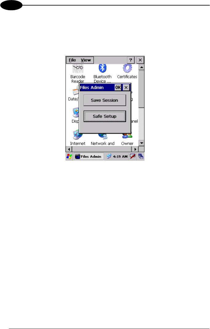
3.7.3 Files Admin
The FILES ADMIN applet enables control of the permanence of files in the System
Folder. Two functions are available on the Files Admin Main window by means of two
buttons:
Files Admin Main Window
Save Session: with this button all files will be permanently saved in the \Windows
directory in non-volatile memory. This function guarantees the steady maintenance of
every file produced during the current working session - even of sub-directories and
relevant files - with the exception of the files belonging to the FLASH image.
These current working session files will be backed-up in the \Backup\Windows
directory.
At the next hardware reset, the files previously saved in the \Backup\Windows
directory will be restored to the Windows directory (see par. 3.9).
Safe Setup: with this button, the installation of software programs will be saved to
non-volatile memory (Backup directory). Before doing this, it will be checked that the
Backup directory has enough space to save the files. If the directory space is not
enough, an error message will be shown and the program will exit the Safe Setup
function.
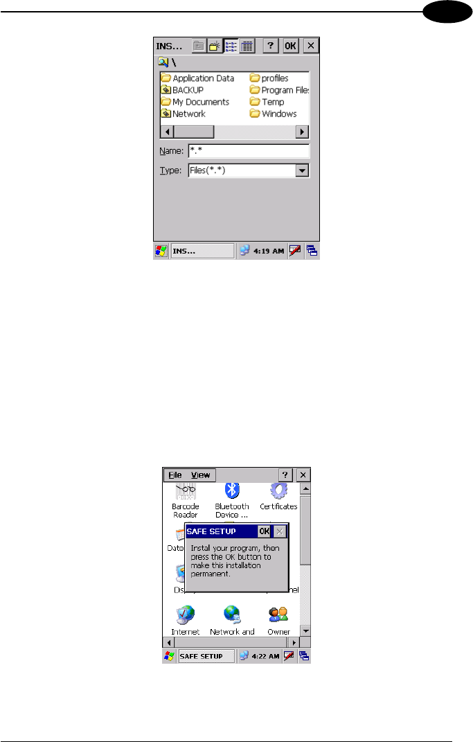
Two activating procedures are available for Safe Setup:
- Select an installation file (for example, a .CAB cabinet file) from the Safe Setup
mask.
USE AND FUNCTIONING
29
3
Safe Setup First Mask
Then select \Windows or a relevant sub-directory in the path box. Then, Safe
Setup will recognize the new files and directories present in the \Windows
directory, and will copy them to the \Backup\Windows directory. At the next
hardware reset, these files will be restored (see par. 3.9).
- Simply skip the first mask either by closing it or by pressing the ESC key. When
it closes, a new mask will pop up: it will enable any type of installation (even
remote ones like ActiveSync® installations). Make sure the installation directory
is \Windows or one of its sub-directories. After installation, tap OK: Safe Setup
will save the new files in the \Backup\Windows directory.
Safe Setup Second Mask
DATALOGIC SKORPIO™
30
3
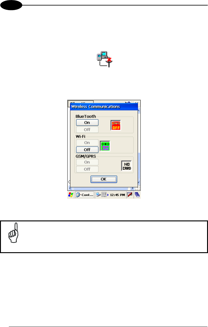
3.7.4 Wireless Communications
The WIRELESS COMMUNICATIONS applet provides management of the Wi-Fi
Card and of the Bluetooth® module.
Select the WIRELESS COMMUNICATIONS applet by double tapping the Wireless
Communications icon. The following window will appear:
Wireless Communications Window
NOTE
In order to avoid wasting power, all modules are off by default.

USE AND FUNCTIONING
31
3
3.7.5 Ethernet Settings
Datalogic Skorpio™ can be connected to an Ethernet network by inserting it into the
Datalogic Skorpio™ Ethernet Multi Cradle.
NOTE
Ethernet communication requires Datalogic Skorpio™ SW version
5.41 or later. Verify the software version by tapping on Software –
Version in the Datalogic default home page. Otherwise, search for
the file version.htm under the Windows folder.
When correctly inserted into the Ethernet Multi Cradle, the Ethernet driver installed
on the mobile computer will automatically run, and using the DHCP service, will
dynamically assign the IP Address.
1. From the Datalogic Skorpio™ open Internet Explorer>Internet Options and
check use LAN no autodial then OK.
2. From the Datalogic Skorpio™ > Explorer, enter the IP address in the address
bar (or name), of the PC on the network that you want to communicate with. You
may be required to enter your network username and password. The LAN
connection will take place and you can see the PC shared folders.
You can download files from the PC to Datalogic Skorpio™ but not vice versa. To do
this use an FTP connection (see par. 3.8.4).
If your network provides Internet Service and does not use a proxy server you can
directly access the Internet. Otherwise set the internet proxy parameters according to
your network settings.
DATALOGIC SKORPIO™
32
3
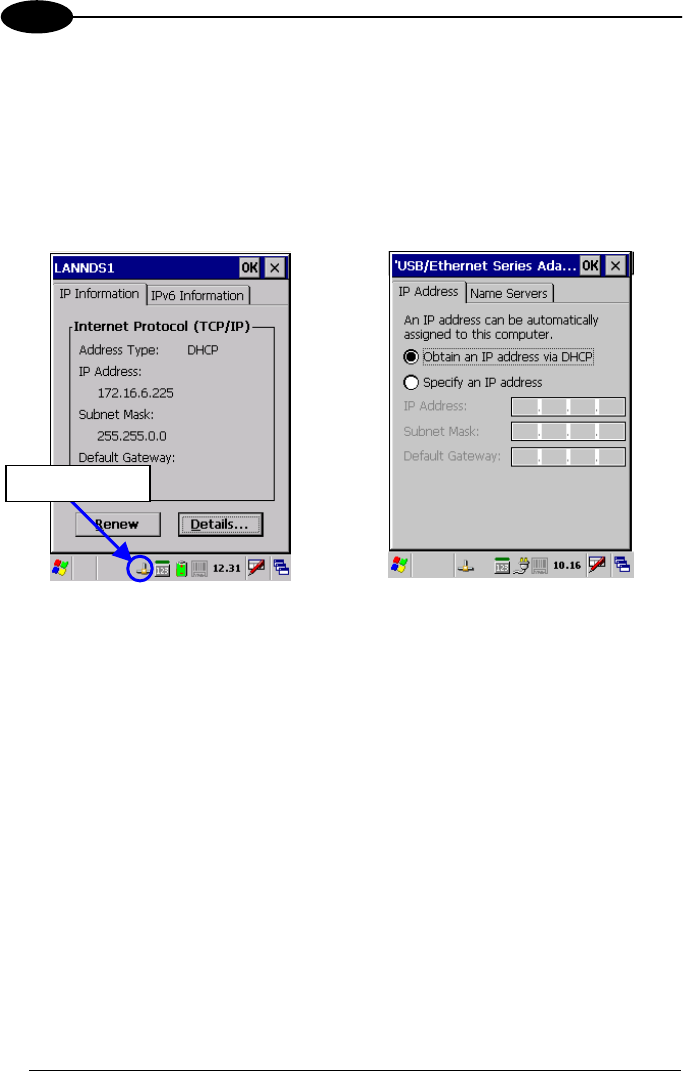
The LAN icon will appear on the Taskbar indicating the LAN connection status.
By double tapping on the LAN icon in the
Taskbar, the LANNDS1 applet allows
visualizing the TCP/IP information. Other
information such as the MAC Address is
available by tapping the Details... button.
If it is necessary to set static TCP/IP
parameters, you must open the
LANNDS1 applet from the Network and
Dial-up Connections applet in the
Control Panel. This applet is only visible
when the mobile computer is correctly
inserted into the Ethernet Multi Cradle.
Ethernet LANNDS1 Communications Window
The IP Address belongs to Datalogic Skorpio™ while the MAC address is specific to
each cradle slot.
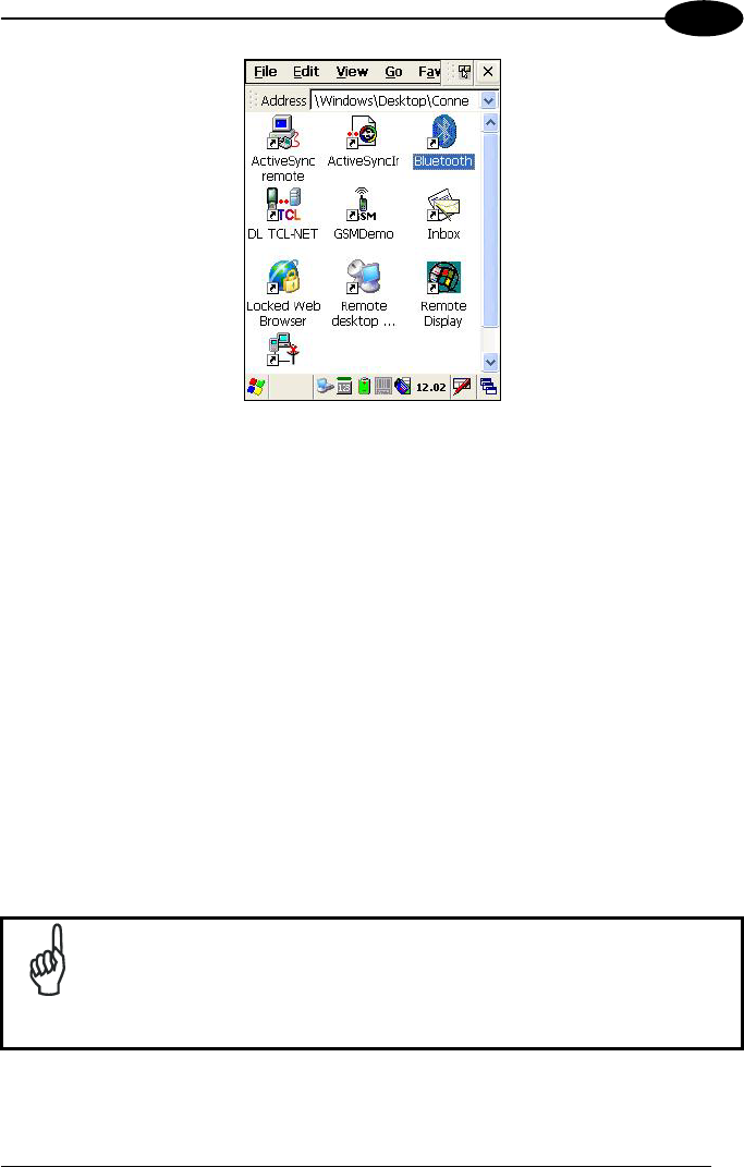
3.8 WINDOWS CONNECTIONS
To connect Datalogic Skorpio™ to another device (i.e. Host PC) from Windows,
several programs are available in the "Connections" folder on the Datalogic
Skorpio™ Desktop. These programs require specific electrical connections in order
to function properly. From the Desktop, double tap on the "Connections" folder to
open the following window:
LAN icon
USE AND FUNCTIONING
33
3
Windows Connections
3.8.1 Microsoft® ActiveSync®
Microsoft® ActiveSync® gives you the possibility to connect your desktop computer to
your Datalogic Skorpio™ and synchronize the information on them. Synchronization
compares the data on the Datalogic Skorpio™ with that on the desktop computer and
updates both computers with the most recent information.
With ActiveSync®, it is possible to:
- Back up and restore Datalogic Skorpio™ data.
- Copy files between Datalogic Skorpio™ and desktop computer.
- Synchronize files by selecting a synchronization mode.
You can establish an ActiveSync® connection to your Datalogic Skorpio™ through
the following electrical interfaces:
USB either directly or through the Datalogic Skorpio™ Single USB Cradle
Bluetooth (see par. 3.8.3)
NOTE
If uploading/downloading files through a serial connection, Microsoft®
ActiveSync® is not used. Refer to par. 3.8.2 for details.

DATALOGIC SKORPIO™
34
3
It is possible to constantly synchronize while connected to a desktop computer or,
alternatively, synchronization can be performed only when the synchronize command
is chosen. You can select which information types are synchronized and control how
much data is synchronized.
NOTE
By default, ActiveSync® does not automatically synchronize all types
of information. Use ActiveSync® options to turn synchronization on
and off for specific information types.
For example:
Synchronize Microsoft Word and Microsoft Excel files between the Datalogic
Skorpio™ and the desktop computer. The files will automatically be converted to the
correct format.
NOTE
Visit the following Microsoft Web site for the latest in updates and
technical information:
http://www.microsoft.com/windowsmobile/activesync/default.mspx
ActiveSync® Remote
NOTE
Microsoft® ActiveSync® Remote is no longer supported in Windows
CE. For backward compatibility you can download it from the internet.
We suggest enabling the FTP Server and connecting to an FTP Client.
See par. 3.8.4.

USE AND FUNCTIONING
35
3
3.8.2 Uploading/Downloading Files through an RS232
Connection
Files can be uploaded/downloaded through the device cradle connected via an
RS232 cable.
Before performing this operation, it is first necessary to define the PC and the mobile
computer settings and connection.
NOTE
If uploading/downloading files through a serial connection, Microsoft®
ActiveSync® is not used.
1 - PC Settings
Follow the procedure to install the modem and define the connection settings:
a) Select Start ->Settings ->Control Panel and run the “Phone and Modem” options;
choose the “Modem” tab and press the “Add” button to make the “Add Hardware
Wizard” window appear;
b) From the “Add Hardware Wizard” window choose “Don’t detect my modem” and
press the “Next” button. Then, choose “Standard Modem” from the
“Manufacturer” list, and “Communications cables between two computers” from
the “Models” list. Select the COM port to be used for connection and press the
“Next” button. Now the modem is available on the installed modem list.
c) From the same (“Add Hardware Wizard”) window select the installed modem
and press the “Properties” button to open a further window where selecting the
“Modem” tab and changing the “Maximum port speed” to 115200. Then, press
the “Ok” button and close all windows to return to Control Panel.
d) From Control Panel choose “Network Connections” to open the related “New
Connection Wizard” window. From this window press the “Next” button, choose
“Set Up an advanced Connection” and press “Next” again. Then, choose “Accept
Incoming Connections”, press “Next”, choose “Communications cables between
two computers” and press “Next” again. Choose if VPN connections are allowed
and press “Next”. Then, it is necessary to select one or more users which can
access the computer or eventually insert a new one through the “Add” button.
Then press “Next” twice to complete the connection.

DATALOGIC SKORPIO™
36
3
2 - Mobile Computer Settings
Follow the procedure to define the connection settings:
a) From the device desktop activate “Control Panel”, then “Network and Dial-up
connections” and choose “Make New Connection”. From this window type your
connection name, select “Direct Connection” and press “Next”. From the device
list select “Serial cable on COM1” and change the communication speed under
“Configure” to 115200 baud. Then, press “Security Settings” and select the
“Preview user name and password” flag. Press “Finish” to save the configuration
and close all windows.
3 –PC Connection
Follow the procedure to start the connection from the PC side:
a) Connect the device cradle to the PC through a serial cable (refer to the cradle
Instruction Manual);
b) Share the desired directories as if working in a typical network connection.
4 –Mobile Computer Connection
Follow the procedure to start the connection from the mobile computer side:
a) Insert the mobile computer into the cradle.
b) Activate “Control Panel”->“Network and Dial-up connections”->“<your connection
name>”. Within the “Enter Network Password” window insert user name and
password (among those allowed in step d) of the PC Settings procedure) and
press the “Ok” button. If the connection succeeds, the “Connected” message will
appear within the “<your connection name>Status” window.
c) Activate “My Device”; then, select “Address Bar” from the “View” menu, insert
\\<host name> and press “Enter” from the keyboard. Insert user name, password
and host domain within the new window.
Now, the directory list will display those directories previously shared by the PC. All
directories can be managed as if working in a typical LAN connection.
USE AND FUNCTIONING
37
3
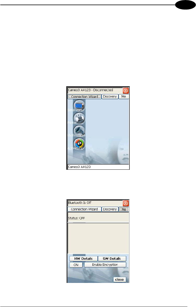
3.8.3 Bluetooth® Manager Device Setup
In order to enable a Bluetooth® device for communication with the Datalogic
Skorpio™ you must perform the discovery procedure and enable the device as
follows:
1. Place the Bluetooth® device within the range of the Datalogic Skorpio™ (10
meters).
2. From the “Connections” folder double tap on the “Bluetooth” applet to open the
Bluetooth® Manager Device window:
3. Tap on the “Me” button to enter the related window; then, tap on the “ON” button
to activate the Bluetooth® module. The module activation may be also performed
by using the WIRELESS COMMUNICATION applet as described in par. 3.7.4.

DATALOGIC SKORPIO™
38
3
By tapping on the “HW Details” and “SW Details” buttons, information about the
mobile computer Bluetooth® hardware and software will be displayed, while the
“Enable Encryption” button starts encryption of the Bluetooth® communication
data. If tapping on the “Close” button the Bluetooth® Manager Device window will
be closed.
4. Tap on the “Discovery” button to enter the related window; then, tap on the
“Scan” button to run the Discovery procedure:
Once the Discovery procedure has been completed, select the desired
Bluetooth® device from the list. It is also possible to digit (12 hexadecimal digits)
the Bluetooth® address of the desired device by tapping on the “Add” button. The
“Clear” button deletes all discovered devices from the list.
5. Once the desired Bluetooth® device has been selected, tap on the “Connection
Wizard” button to enter the related window where selecting the connection type
to be used for communication with the Bluetooth® device:

USE AND FUNCTIONING
39
3
The “Serial Port” button starts communication through the Bluetooth® serial port
COM 5.
The “Printer” button starts communication with a printer through the Bluetooth®
serial port COM 5.
The “Kbd Emulation” button allows connection with a barcode reader using the
keyboard emulation.
The “ActiveSync” button starts communication with a PC equipped with a
Bluetooth® antenna and the related ActiveSync.
6. Hide the Bluetooth® Manager Device window by tapping on the icon
available on each window or close it through the “Close” button available in the
“Me” window (see step 3 of this procedure).
3.8.4 FTP Server Setup
The Datalogic Skorpio™ Operating System includes a sample File Transfer Protocol
(FTP) server. FTP is used for copying files to and from remote computer systems
over a network using TCP/IP. You can establish a connection to your Datalogic
Skorpio™ using its FTP Server through the following interfaces:
WLAN using the WiFi radio
LAN through the Datalogic Skorpio™ Ethernet Multi Cradle (see par. 3.7.5)
Proceed as follows:
1. Create a registry file (extension .reg) to setup and enable FTP Server
communication. A simple example file for anonymous logon is given below:
REGEDIT4
[HKEY_LOCAL_MACHINE\Comm\FTPD]
"DefaultDir"="\\"
"AllowAnonymousUpload"=dword:00000001
"UseAuthentication"=dword:00000000
"BaseDir"="\\"
"IsEnabled"=dword:00000001
"LogSize"=dword:00001000
"DebugOutputMask"=dword:00000017
"DebugOutputChannels"=dword:00000002
"IdleTimeout"=dword:0000012c
"AllowAnonymous"=dword:00000001
"AllowAnonymousVroots"=dword:00000001
2. Copy this file to the Datalogic Skorpio™ using ActiveSync® or the RS232
protocol (par. 3.8.2).

DATALOGIC SKORPIO™
40
3
3. Launch the .reg file from the Datalogic Skorpio™.
4. Perform a software reset on the Datalogic Skorpio™.
5. From the PC > Explorer address bar (or running an FTP Client from the PC),
enter the Datalogic Skorpio™ IP address.
NOTE
For more information on FTP Client/Server connections refer to the
following web page:
http://msdn2.microsoft.com/en-us/library/aa922316.aspx.
NOTE
Datalogic Skorpio™ xxx-xxx-433 and xxx-xxx-436 models do not
contain the FTP Server. If necessary you can install it from the CD-
ROM in the Utilities folder.
3.9 BACKUP DIRECTORY FILE MANAGEMENT
All of the Windows CE system files reside in RAM (volatile memory) except for the
Backup directory, which resides in FLASH (non-volatile memory). Therefore the
contents of the Backup directory are persistent even if the mobile computer is re-
booted or the battery pack is changed.
You can save your more important files that you don't want to lose due to mobile
computer re-boot, in the Backup directory or create a sub-directory within Backup.
Even though the Windows Directory resides in RAM, it often contains files or sub-
directories created by the user or by installation programs that you don't want to lose
at re-boot. To keep these files persistent it is necessary to copy them to the directory
\Backup\Windows. This directory doesn't exist originally (only Backup exists), and
therefore it must be created. At the next hardware reset, before activating the shell,
Windows CE will copy the contents including all sub-directories of \Backup\Windows
to \Windows.
Likewise, to maintain files that must be run at Windows CE startup, (i.e. .exe, .lnk,
.vb, .htm, etc.), it is necessary to copy them to the directory \Backup\Startup. This
directory does not exist originally (only Backup exists), and therefore it must be
created. The application programs will be run after any type of re-boot (both software
and hardware reset).

USE AND FUNCTIONING
41
3
As an alternative to the Safe Setup function, it is possible to copy the .cab files to the
directory \Backup\Cabfiles (the Cabfiles sub-directory doesn't exists originally and
must therefore be created) and perform a mobile computer cold boot to have the
application installed. Once these files are copied to the directory \Backup\Cabfiles,
the application will be run after each re-boot.
From the second cold boot on, a message may be displayed such as "<application
name> is already installed. Re-install?". This message blocks the boot process.
Press the [Enter] key to continue the system initialization.
DATALOGIC SKORPIO™
42
4
4 MAINTENANCE
NOTE
Rechargeable battery packs are not initially charged. Therefore the
first operation to perform is to charge them. See below.
4.1 CHARGING THE BATTERY PACK
The battery pack autonomy varies according to factors, such as the frequency of
barcode scanning, RF usage, etc.
When the battery pack is low, the LED positioned at the right side of the display
blinks red.
It is possible to recharge the battery pack by using the PG5-20 MiniUSB AC/DC
Power Supply directly connected to the Datalogic Skorpio™.
Alternatively, it is also possible to recharge the battery pack by using the
Datalogic Skorpio™ Single USB Cradle or one of the Datalogic Skorpio™/F-COLOR
cradles (even when not connected to the host).
During the charging process the LED positioned at the right side of the display is red
constant. Once the charging process has been completed this LED is green constant
(see par. 3.5).
If the battery pack is removed from the mobile computer, it can be recharged by
inserting it into the MBC8600 Multi-Battery Charger.
CAUTION
If the battery pack is new or has not been recharged for a long time,
it is necessary to perform two or three charging and discharging
cycles (complete use) before it can reach its maximum charge
capability.
The maximum time required to recharge a completely run-down
battery pack is 4 hours if recharged into the mobile computer.
MAINTENANCE
43
4
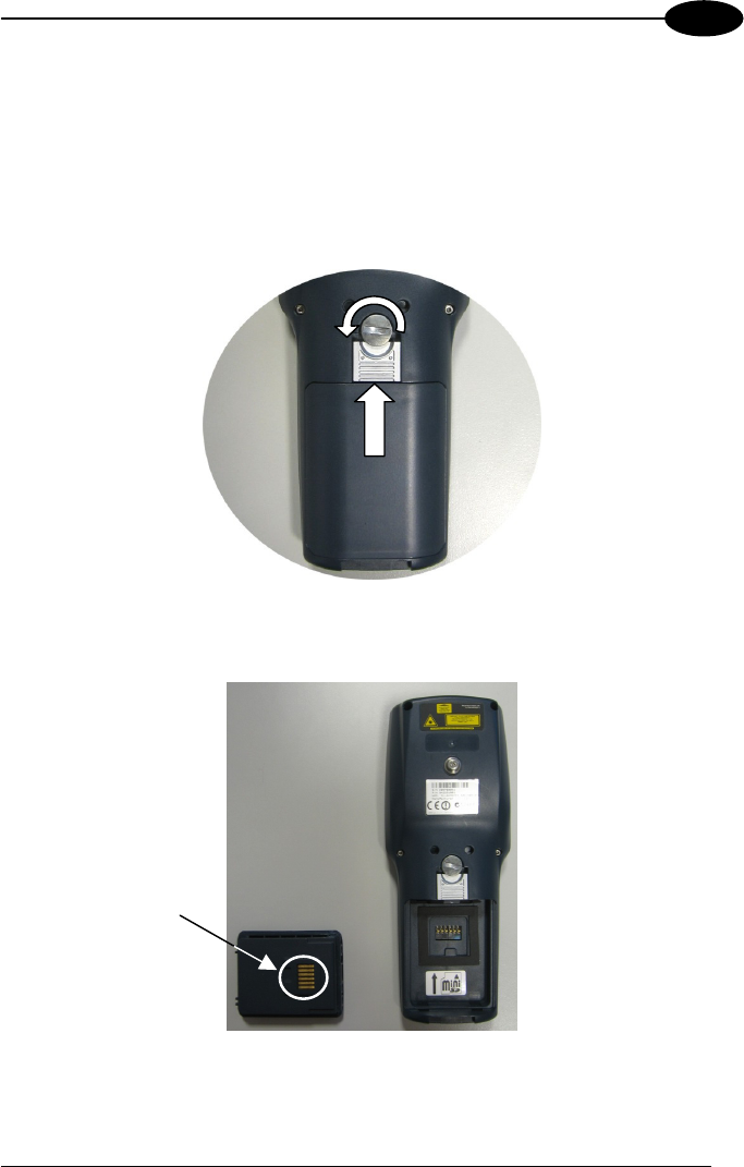
4.2 REPLACING THE BATTERY PACK
To correctly replace the battery pack, proceed as follows.
1. Turn off the Datalogic Skorpio™.
2. Turn the battery lock screw to the open position (horizontal), then pull the lock
runner up, as indicated in the figure below.
3. Remove the battery pack.
Battery Contacts
DATALOGIC SKORPIO™
44
4
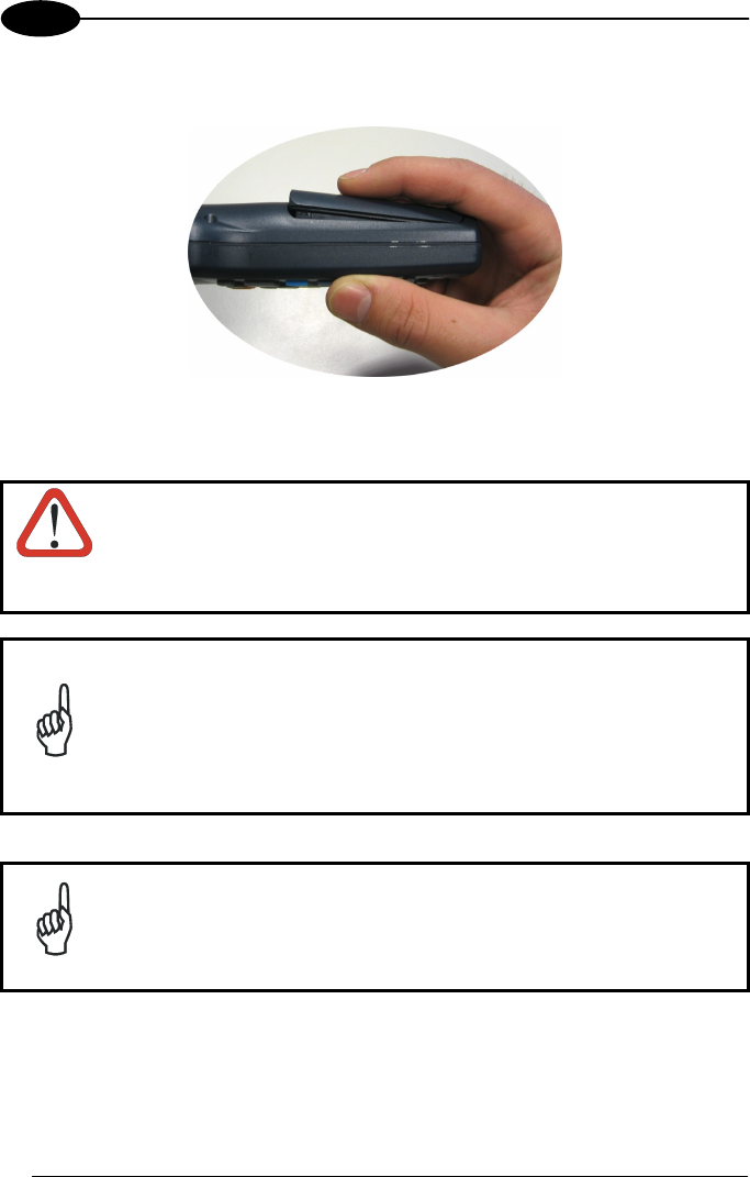
4. To correctly insert the new battery pack, first insert the bottom and then the
upper part of the battery pack into the slot as indicated in the following figure:
5. Press it until the battery latch is automatically closed.
WARNING
Do not incinerate, disassemble, short terminals or expose to
high temperature. Risk of fire, explosion. Use specified charger
only. Risk of explosion if the battery is replaced by an
incorrect type. Dispose of the batteries as required by the
relevant laws in force.
NOTE
In order to guarantee an adequate operating autonomy, when
replacing the battery pack the mobile computer checks the battery
energy level. If the battery is not sufficiently charged, Datalogic
Skorpio™ does not turn on (when pressing the ON button).
In this case, either substitute the battery pack with a charged one
(sufficiently charged) or insert Datalogic Skorpio™ into a powered
cradle or plug it into the direct power supply.
NOTE
Due to a large internal capacitor, Datalogic Skorpio™ can remain
on for about two minutes with no loss of data in the volatile memory,
for example when replacing the battery pack.
MAINTENANCE
45
4
4.3 COMPACT FLASH AND SECURE STORAGE CARDS
The Datalogic Skorpio™ supports both Compact Flash and Mini Secure Digital
storage cards.
The Mini Secure Digital storage card slot accepts storage cards only, while the
Compact Flash card slot accepts either a storage card or a 802.11b/g radio card.
To install a Compact Flash, it is recommended to contact a Datalogic representative
for technical assistance since to access the card slot it is necessary to open the
mobile computer by removing its screws and causes warranty loss, while the Mini
Secure Digital storage card can be installed by removing the battery, without opening
the mobile computer.
CAUTION
Opening the Datalogic Skorpio™ may damage internal
components.
4.4 CLEANING THE MOBILE COMPUTER
Periodically clean the Datalogic Skorpio™ with a slightly dampened cloth.
Do not use alcohol, corrosive products or solvents.
DATALOGIC SKORPIO™
46
5
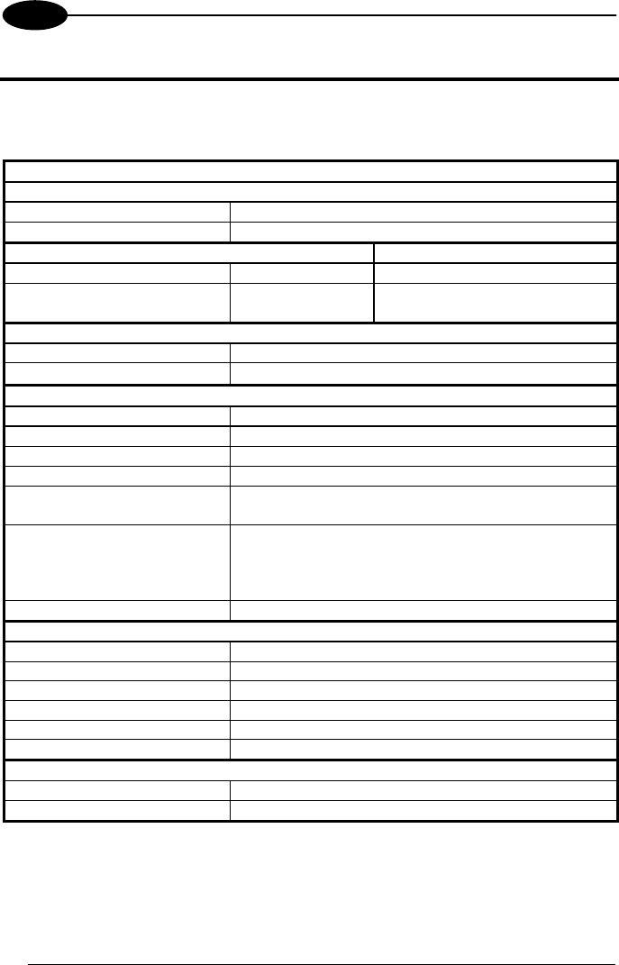
5 TECHNICAL FEATURES
5.1 TECHNICAL DATA
Electrical Features
Power
DC supply 5.25 V ± 6%
Battery pack 2 cell Li-Ion 2100 mAh@ 3.7 V (7.8 Watt-hours)
Communication Features Windows CE COM Port
Bluetooth interface COM5
Serial interface RS232
USB 1.1
COM1
COM6
Wireless Features
WLAN IEEE 802.11b or b/g DSSS
WPAN Bluetooth® IEEE 802.15, Class 2, Version 1.2
Hardware Features
FLASH 64/128 MB *
RAM 64/128 MB *
Microprocessor Intel X-Scale PXA-270 @ 312/520 MHz *
Audio Speaker, Microphone
LED Two-color Good Read/Programmable LED
Charging Status (two-color LED)
Display 65K Color TFT LCD, 2.8”, 320 x 240 pixel resolution
(QVGA), with LED backlight and touch screen,
transflective lighting, antiglare and antiscratch
protection
Keyboard 38 Rubber Keys
Environmental Features
Working temperature** -10° to + 50 °C / 14° to +122 °F
Storage temperature -20° to +70 °C / -4° to +158 °F
Humidity 90% non condensing for temperatures<40°C
Protection IP64
ESD protection 4 KV contact discharge, 8 KV air discharge
Drop resistance 1.5 m / 5 ft
Mechanical Features
Dimensions (LxWxH) 19.6 x 7.7 x 3.3 cm / 7.7 x 3.0 x 1.3 in
Weight (depending on model) 310 - 360 g / 10.9 - 12.7 oz (incl. battery)
* Depending on models.
** Batteries must be charged at a temperature ranging from 0° to +45 °C (+32° to +113 °F).
At temperatures below 0° and above + 45 °C display or battery performance degradation
may occur.

TECHNICAL FEATURES
47
5
Programming Features
Operating system Windows CE 5.0 Core/Professional
Laser Models
Decoded barcodes 1D UPC A, UPC E, EAN 8, EAN 13, Code 39, Code 39
Full ASCII, Code 32, Interleaved 2 of 5, Industrial 2 of
5, Matrix 2 of 5, Code 128, EAN 128, Codabar, MSI,
Plessey, Code 93, Code 11
Laser Optical Features
Maximum resolution 0.10 mm / 4 mils
Skew angle ± 50°
Pitch angle ± 65°
Scan rate - bidirectional 104 ± 12 scan/sec
Light source laser scanner VLD, wavelength in the range 630 to 680 nm
Safety class Class II EN 60825-1/CDRH
5.2 READING DIAGRAM

DATALOGIC SKORPIO™
48
6
6 TEST CODES
High Density Codes
0.25 mm (10 mils)
Code 39
!17162H!
17162
2/5 Interleaved
Ë"8NduÌ
0123456784
Code 128
ÌtestwÎ
test
80%
EAN 13 x(0B2DE5*KKKKLM(
80%
EAN 8 (6450*TRMN(

TEST CODES
49
6
Medium Density Codes
0.38 mm (15 mils)
Code 39
!17162H!
17162
Interleaved 2/5
Ë"8NduÌ
0123456784
Code 128
ÌtestwÎ
test
100%
EAN 13 x(0B2DE5*KKKKLM(
100%
EAN 8 (6450*TRMN(

DATALOGIC SKORPIO™
50
6
Low Density Codes
0.50 mm (20 mils)
Code 39
!17162H!
17162
Interleaved 2/5
Ë"8NduÌ
0123456784
Code 128
ÌtestwÎ
test
120%
EAN 13 x(0B2DE5*KKKKLM(
120%
EAN 8 (6450*TRMN(

51
GLOSSARY
Access Point
A device that provides transparent access between Ethernet wired networks and
IEEE 802.11 interoperable radio-equipped mobile units. Hand-held mobile
computers, PDAs or other devices equipped with radio cards, communicate with
wired networks using Access Points (AP). The mobile unit (mobile computer) may
roam among the APs in the same subnet while maintaining a continuous, seamless
connection to the wired network.
Barcode
A pattern of variable-width bars and spaces which represents numeric or
alphanumeric data in binary form. The general format of a barcode symbol consists
of a leading margin, start character, data or message character, check character (if
any), stop character, and trailing margin. Within this framework, each recognizable
symbology uses its own unique format.
Baud Rate
A measure for data transmission speed.
Bit
Binary digit. One bit is the basic unit of binary information. Generally, eight
consecutive bits compose one byte of data. The pattern of 0 and 1 values within the
byte determines its meaning.
Bluetooth®
A standard radio technology using a proprietary protocol. The onboard Bluetooth
module in the mobile computer is compatible with the 1.2 protocol.
Byte
On an addressable boundary, eight adjacent binary digits (0 and 1) combined in a
pattern to represent a specific character or numeric value. Bits are numbered from
the right, 0 through 7, with bit 0 the low-order bit. One byte in memory can be used to
store one ASCII character.
Decode
To recognize a bar code symbology (e.g., Codabar, Code 128, Code 3 of 9,
UPC/EAN, etc.) and analyze the content of the bar code scanned.
EEPROM
Electrically Erasable Programmable Read-Only Memory. An on-board non-volatile
memory chip.

52
Flash Disk
Non-volatile memory for storing application and configuration files.
Host
A computer that serves other mobile computers in a network, providing services such
as network control, database access, special programs, supervisory programs, or
programming languages.
Liquid Crystal Display (LCD)
A display that uses liquid crystal sealed between two glass plates. The crystals are
excited by precise electrical charges, causing them to reflect light outside according
to their bias. They use little electricity and react relatively quickly. They require
external light to reflect their information to the user.
Light Emitting Diode (LED)
A low power electronic light source commonly used as an indicator light. It uses less
power than an incandescent light bulb but more than a Liquid Crystal Display (LCD).
RAM
Random Access Memory. Data in RAM can be accessed in random order, and
quickly written and read.
RF
Radio Frequency.
RTC
Real Time Clock.

53
INDEX
A
Accessories; 7
Available Models; 2
B
Backup Directory File Management;
40
Bluetooth® Manager Device Setup;
37
Buttons; 26
C
Charging the Batteries; 42
Cleaning the Mobile Computer; 45
Connections; 8
Ethernet Connection; 10
Modem Connection; 10
RS232 Connection; 9
USB Connection; 8
WLAN Connection; 11
WPAN Connections; 12
Control Panel; 26
D
Data Capture; 15
Laser Data Capture; 15
Data Capture Configuration; 21
Datalogic Skorpio™ Description; 1
Default Settings; 24
Description of the Keys; 16
E
End User License Agreement; v
Ethernet Cradle Settings; 31
F
Files Admin; 28
FTP Server Setup; 39
G
General View; xiv
Glossary; 51
M
Maintenance; 42
Microsoft® ActiveSync®; 33
P
Package Contents; 2
R
Reader Parameters; 23
References; vii
Registry; 27
Replacing the Batteries; 43
S
Safe Setup; 28
Safety Regulations; viii
Laser Safety; ix
Radio Compliance; xii
Save Session; 28
Scan Parameters; 23
Services and Support; vii
Startup; 13
Status Indicators; 19
T
Technical Features; 46
Test Codes; 48
U
Using the Stylus; 14
W
Wireless Communication; 30

54
07
Datalogic Mobile S.r.l.
Via S. Vitalino 13
40012 - Lippo di Calderara
Bologna - Italy
dichiara che
declares that the
déclare que le
bescheinigt, daß das Gerät
declare que el
Datalogic Skorpio XXX-YYY-ZZZ
e tutti i suoi modelli
and all its models
et tous ses modèles
und seine Modelle
y todos sus modelos
sono conformi alle Direttive del Consiglio Europeo sottoelencate:
are in conformity with the requirements of the European Council Directives listed below:
sont conformes aux spécifications de la Directives de l'Union Européenne ci-dessous:
der nachstehenden angeführten Direktiven des Europäischen Rats:
cumple con los requisitos de las Directivas del Consejo Europeo, según la lista siguiente:
1999/5/EEC R&TTE
Questa dichiarazione è basata sulla conformità dei prodotti alle norme seguenti:
This declaration is based upon compliance of the products to the following standards:
Cette déclaration repose sur la conformité des produits aux normes suivantes:
Diese Erklärung basiert darauf, daß das Produkt den folgenden Normen entspricht:
Esta declaración se basa en el cumplimiento de los productos con las siguientes normas:
ETSI EN 301 489-3 v1.4.1, August 2002: ELECTROMAGNETIC COMPATIBILITY AND RADIO SPECTRUM MATTERS (ERM);
ELECTROMAGNETIC COMPATIBILTY (EMC) STANDARD FOR RADIO EQUIPMENT
AND SERVICES; PART 3: SPECIFIC CONDITIONS FOR SHORT-RANGE DEVICES
(SRD) OPERATING ON FREQUENCIES BETWEEN 9KHZ AND 40 GHZ
ETSI EN 301 489-17 v1.2.1, August 2002: ELECTROMAGNETIC COMPATIBILITY AND RADIO SPECTRUM MATTERS (ERM);
ELECTROMAGNETIC COMPATIBILITY (EMC) STANDARD FOR RADIO EQUIPMENT
AND SERVICES; PART 17: SPECIFIC CONDITIONS FOR 2,4GHZ WIDEBAND
TRANSMISSION SYSTEMS AND 5GHZ HIGH PERFORMANCE RLAN EQUIPMENT
ETSI EN 300 328 v1.6.1, November 2004: ELECTROMAGNETIC COMPATIBILITY AND RADIO SPECTRUM MATTERS (ERM);
WIDEBAND TRANSMISSION SYSTEMS; DATA TRANSMISSION EQUIPMENT
OPERATING IN THE 2,4 GHZ ISM BAND AND USING WIDE BAND MODULATION
TECHNIQUES; HARMONIZED EN COVERING ESSENTIAL REQUIREMENTS UNDER
ARTICLE 3.2 OF THE R & TTE DIRECTIVE

55
ETSI EN 300 330-2 v1.1.1, June 2001: ELECTROMAGNETIC COMPATIBILITY AND RADIO SPECTRUM MATTERS (ERM);
SHORT RANGE DEVICES (SRD); RADIO EQUIPMENT IN THE FREQUENCY RANGE
9 KHZ TO 25 MHZ AND INDUCTIVE LOOP SYSTEMS IN THE FREQUENCY RANGE 9
KHZ TO 30 MHZ; PART 2: HARMONIZED EN UNDER ARTICLE 3.2 OF THE
R&TTE DIRECTIVE
EN 60950-1, December 2001: InFORMATION TECHNOLOGY EQUIPMENT – SAFETY –
PART 1: GENERAL REQUIREMENTS
Lippo di Calderara, March 9th, 2007
Paola Chientaroli
Quality Assurance Manager
www.mobile.datalogic.com
Datalogic Skorpio™
User's Manual