Datalogic S r l 0020 DL-SKORPIO User Manual b Datalogic Skorpio Master
Datalogic ADC S.r.l. DL-SKORPIO b Datalogic Skorpio Master
UserManual.wiki
>
Datalogic S r l
>
0020 User Manual
>
Usermanual part 2
Contents
1.
Usermanual part 1
2.
Usermanual part 2
3.
Integration Guide
Usermanual part 2
Navigation menu
Upload a User Manual
Namespaces
Wiki Guide
HTML
PDF
Info
Views
User Manual
Discussion / Help
Navigation
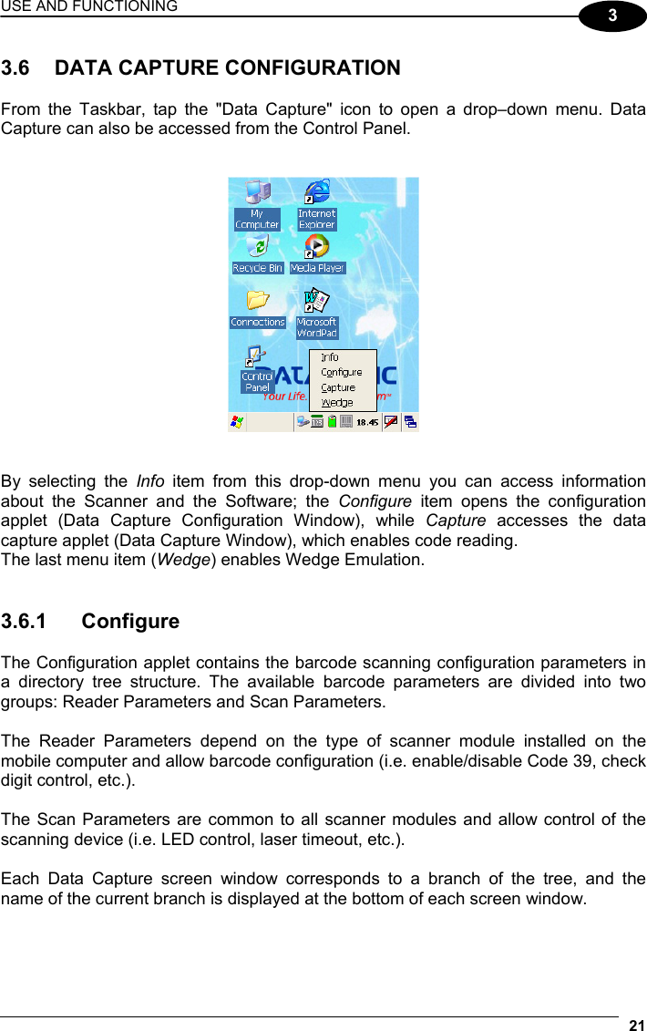

![USE AND FUNCTIONING 39 3 The “Serial Port” button starts communication through the Bluetooth® serial port COM 5. The “Printer” button starts communication with a printer through the Bluetooth® serial port COM 5. The “Kbd Emulation” button allows connection with a barcode reader using the keyboard emulation. The “ActiveSync” button starts communication with a PC equipped with a Bluetooth® antenna and the related ActiveSync. 6. Hide the Bluetooth® Manager Device window by tapping on the icon available on each window or close it through the “Close” button available in the “Me” window (see step 3 of this procedure). 3.8.4 FTP Server Setup The Datalogic Skorpio™ Operating System includes a sample File Transfer Protocol (FTP) server. FTP is used for copying files to and from remote computer systems over a network using TCP/IP. You can establish a connection to your Datalogic Skorpio™ using its FTP Server through the following interfaces: WLAN using the WiFi radio LAN through the Datalogic Skorpio™ Ethernet Multi Cradle (see par. 3.7.5) Proceed as follows: 1. Create a registry file (extension .reg) to setup and enable FTP Server communication. A simple example file for anonymous logon is given below: REGEDIT4 [HKEY_LOCAL_MACHINE\Comm\FTPD] "DefaultDir"="\\" "AllowAnonymousUpload"=dword:00000001 "UseAuthentication"=dword:00000000 "BaseDir"="\\" "IsEnabled"=dword:00000001 "LogSize"=dword:00001000 "DebugOutputMask"=dword:00000017 "DebugOutputChannels"=dword:00000002 "IdleTimeout"=dword:0000012c "AllowAnonymous"=dword:00000001 "AllowAnonymousVroots"=dword:00000001 2. Copy this file to the Datalogic Skorpio™ using ActiveSync® or the RS232 protocol (par. 3.8.2).](https://usermanual.wiki/Datalogic-S-r-l/0020.Usermanual-part-2/User-Guide-799047-Page-19.png)
![USE AND FUNCTIONING 41 3 As an alternative to the Safe Setup function, it is possible to copy the .cab files to the directory \Backup\Cabfiles (the Cabfiles sub-directory doesn't exists originally and must therefore be created) and perform a mobile computer cold boot to have the application installed. Once these files are copied to the directory \Backup\Cabfiles, the application will be run after each re-boot. From the second cold boot on, a message may be displayed such as "<application name> is already installed. Re-install?". This message blocks the boot process. Press the [Enter] key to continue the system initialization.](https://usermanual.wiki/Datalogic-S-r-l/0020.Usermanual-part-2/User-Guide-799047-Page-21.png)