Datalogic S r l 004W 802.11ag Mini Compact Flash Module User Manual SkorpioX3 CE
Datalogic ADC S.r.l. 802.11ag Mini Compact Flash Module SkorpioX3 CE
UserManual.wiki
>
Datalogic S r l
>
004W User Manual
>
user manual
Contents
1.
User Manual
2.
user manual
user manual
Navigation menu
Upload a User Manual
Namespaces
Wiki Guide
HTML
PDF
Info
Views
User Manual
Discussion / Help
Navigation
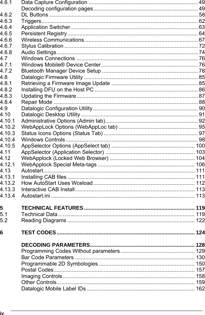
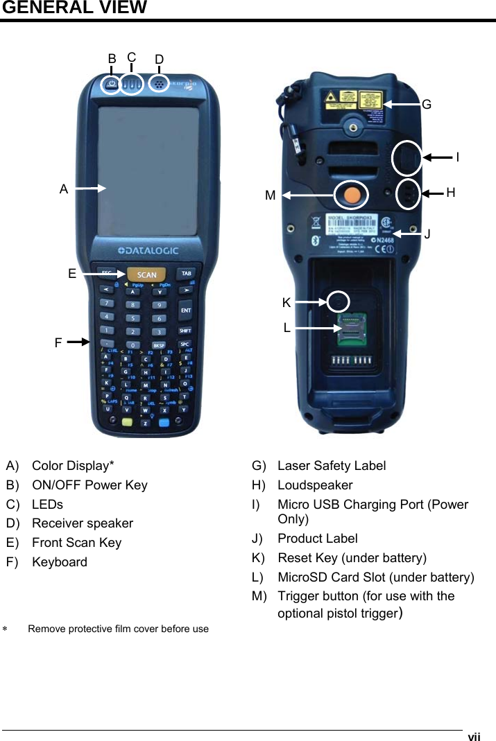
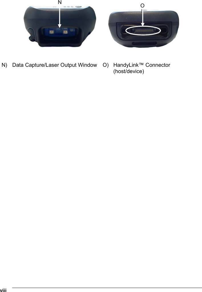
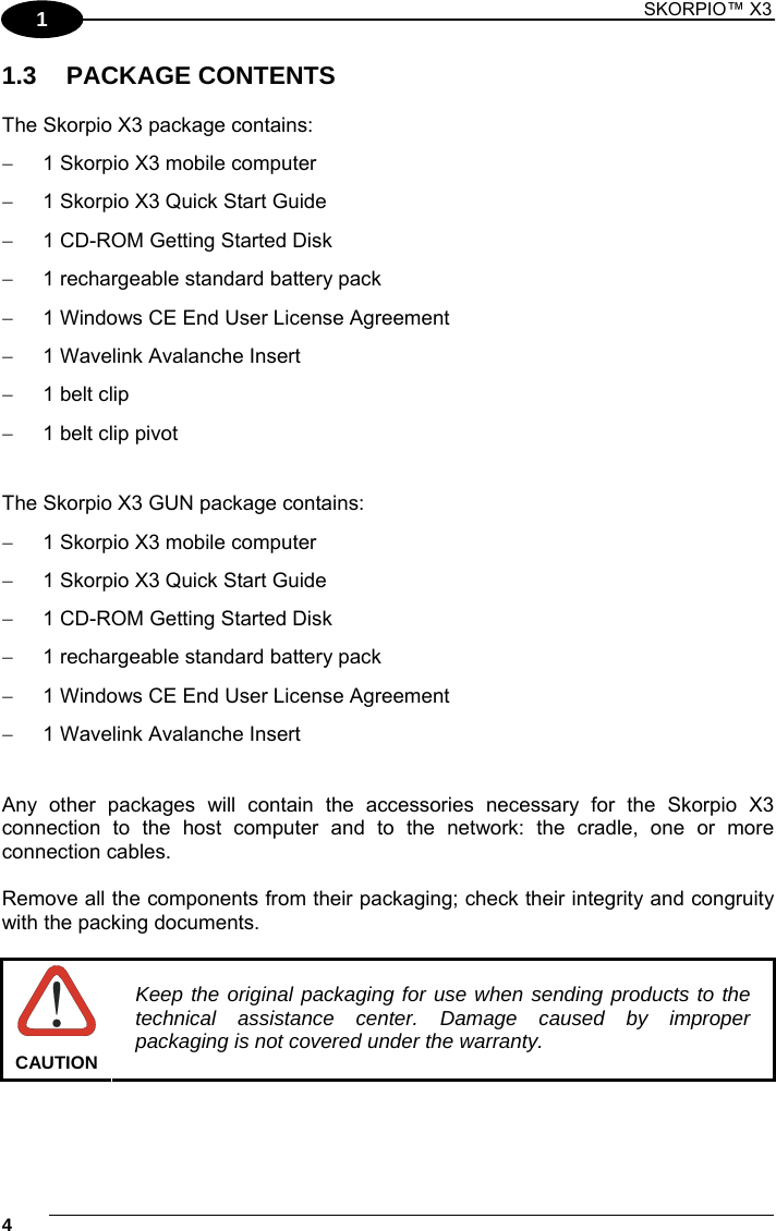
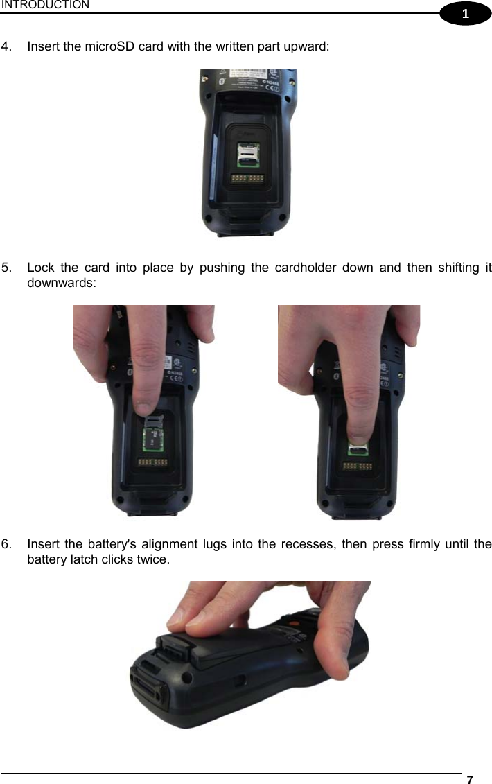
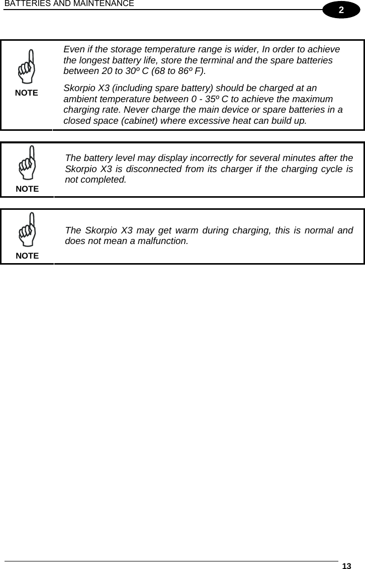
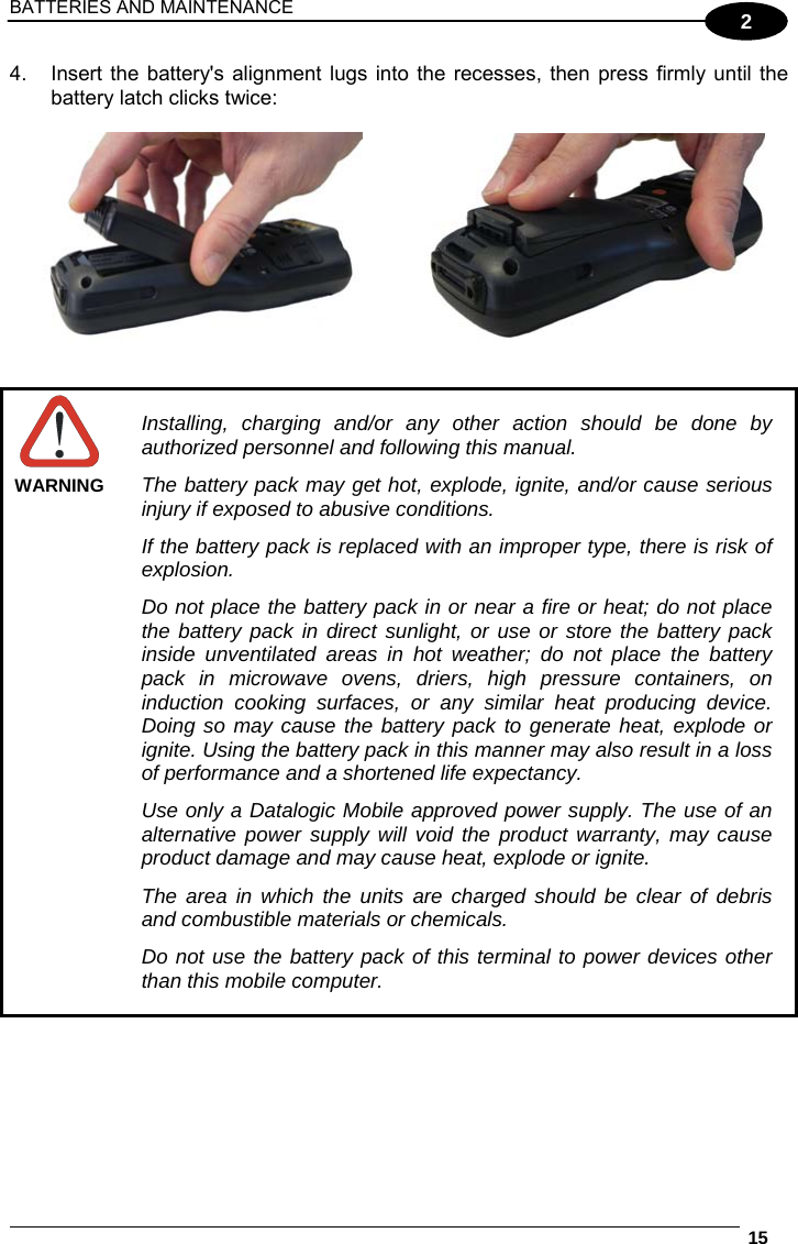
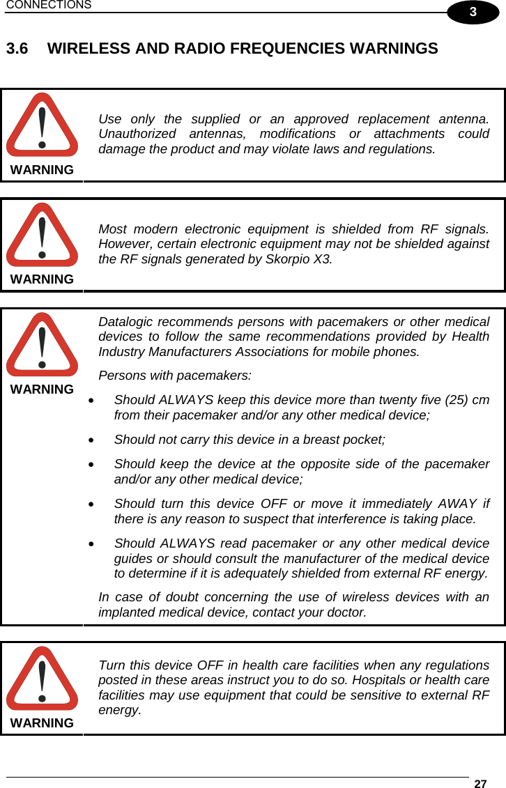
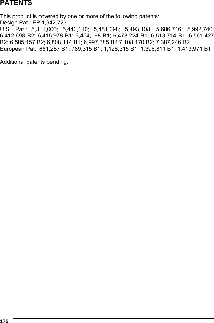
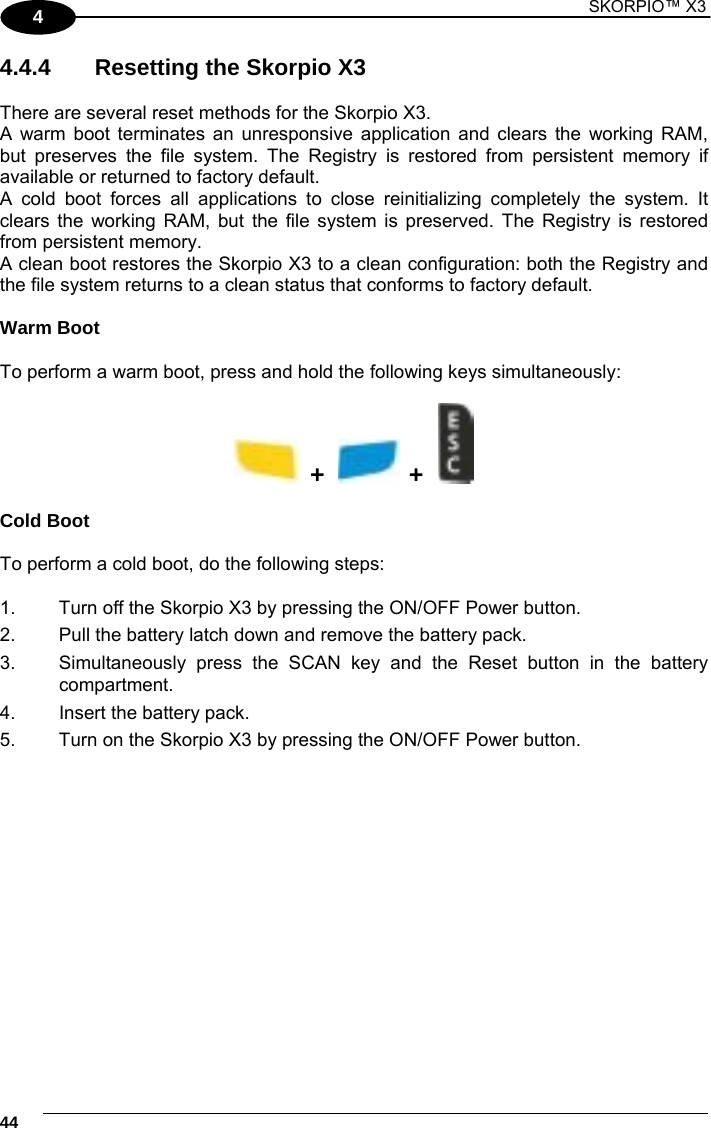
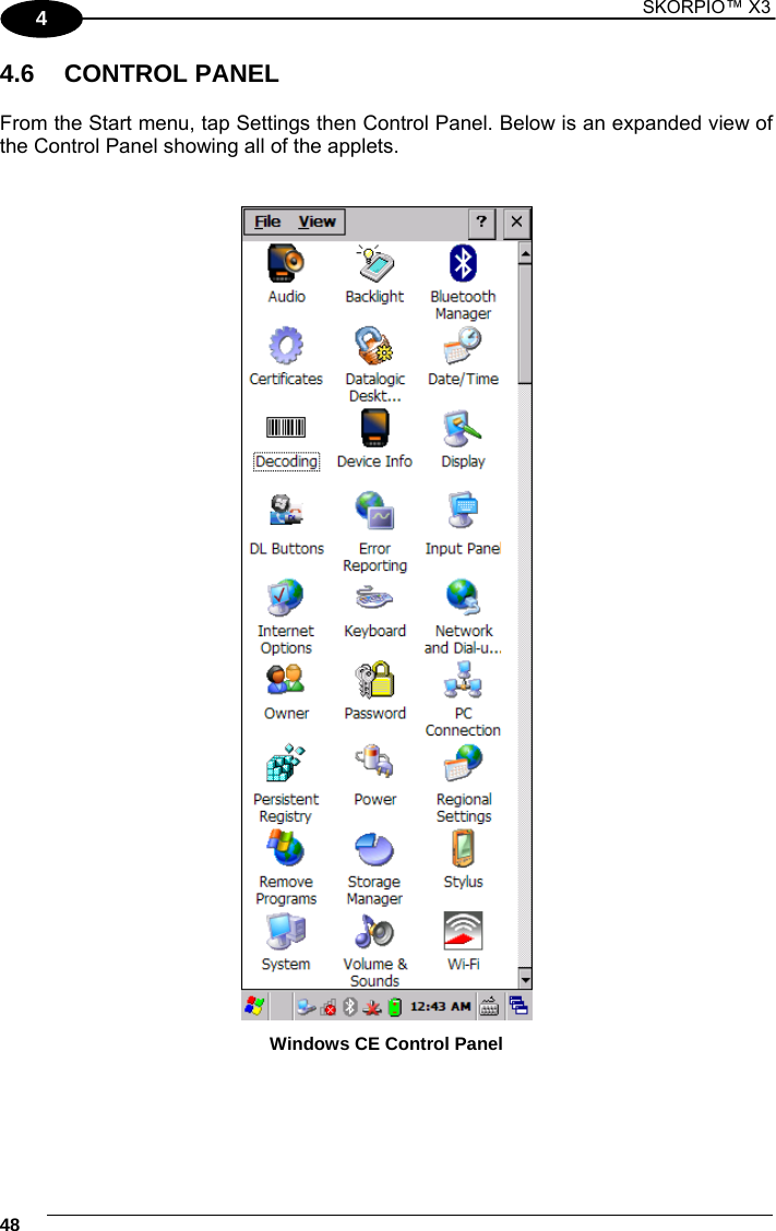
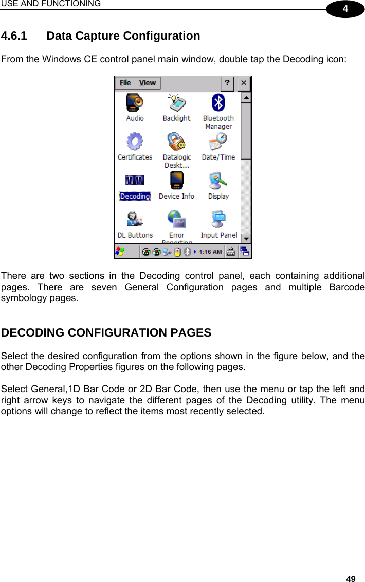
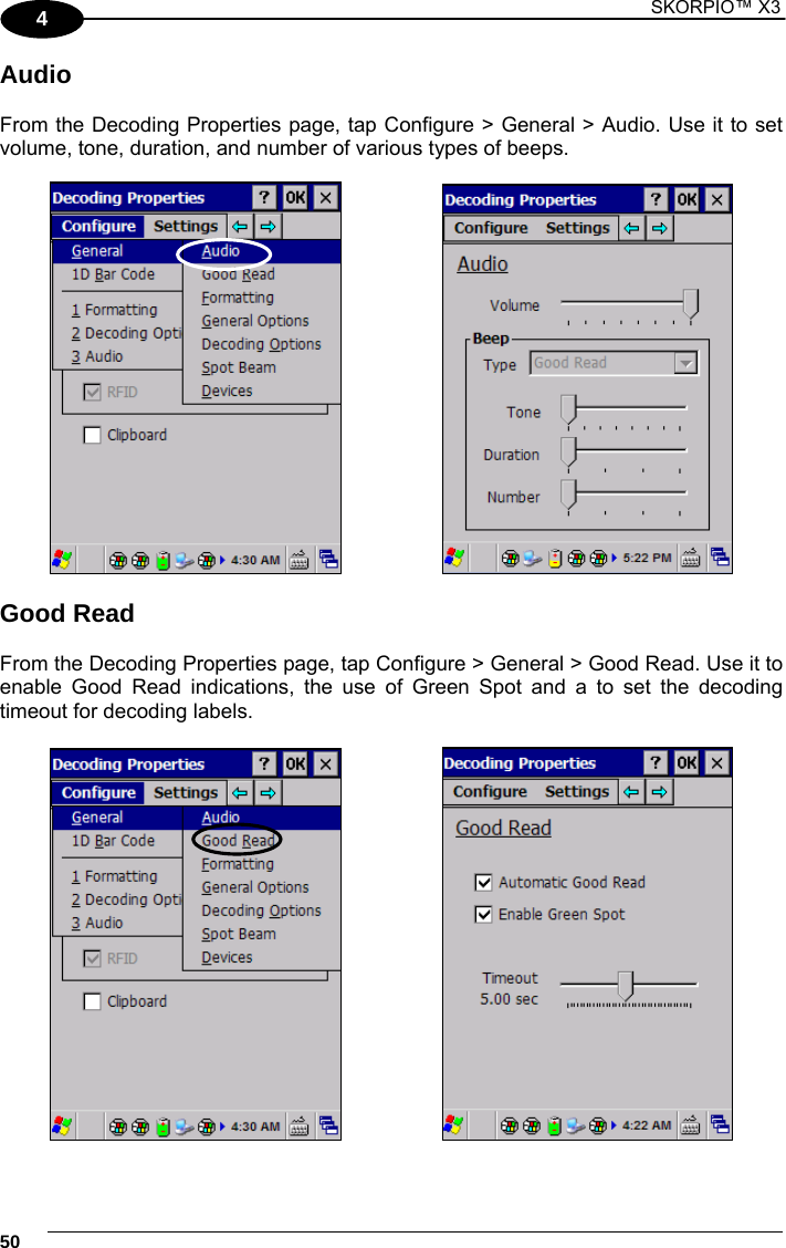
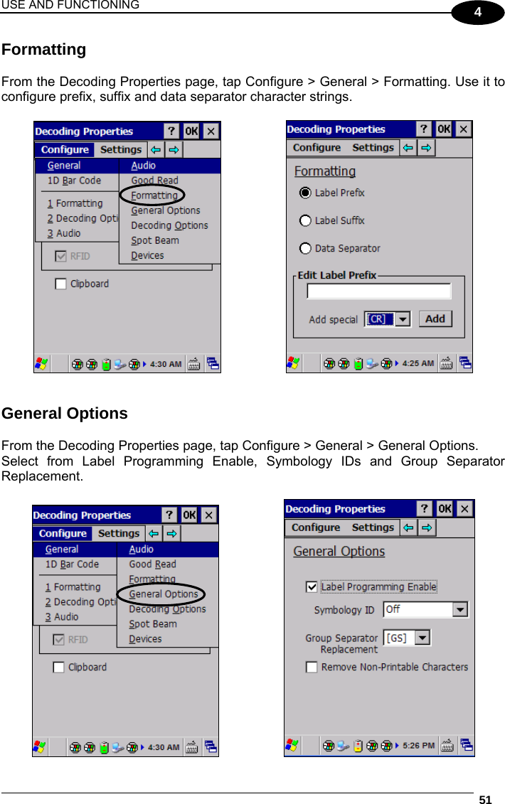
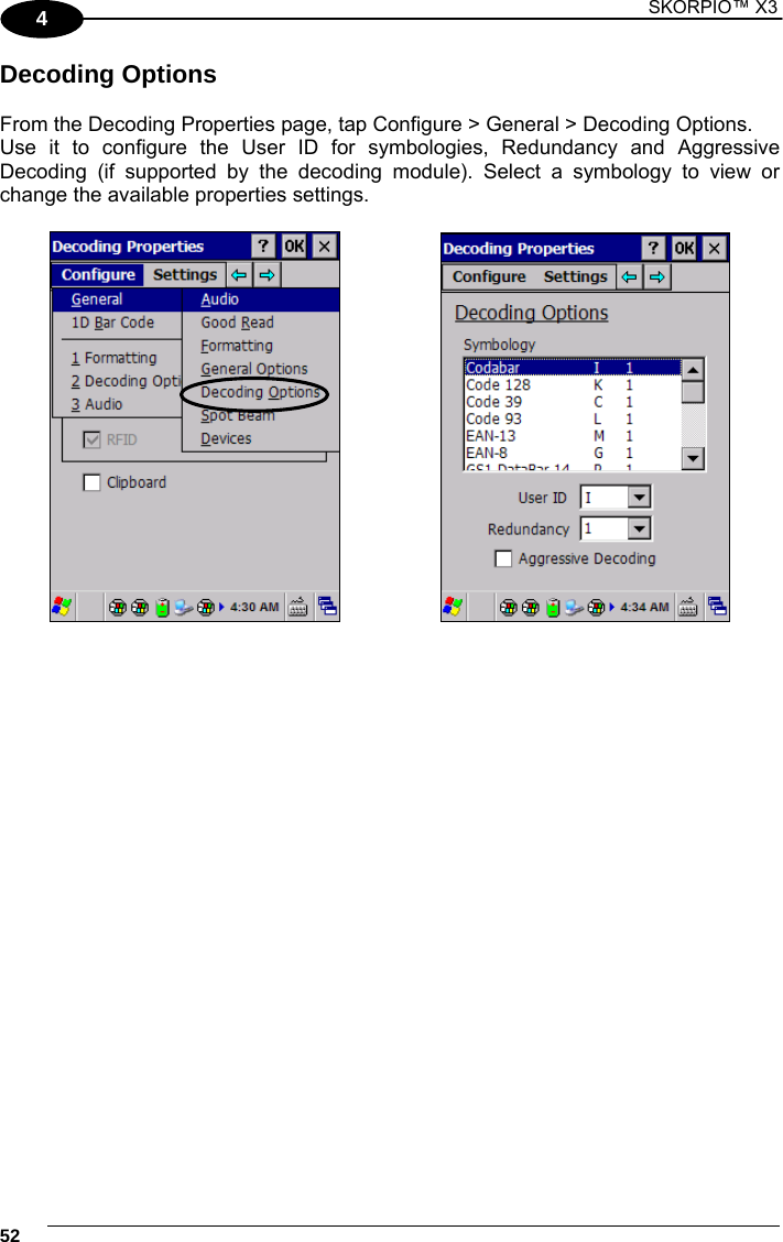
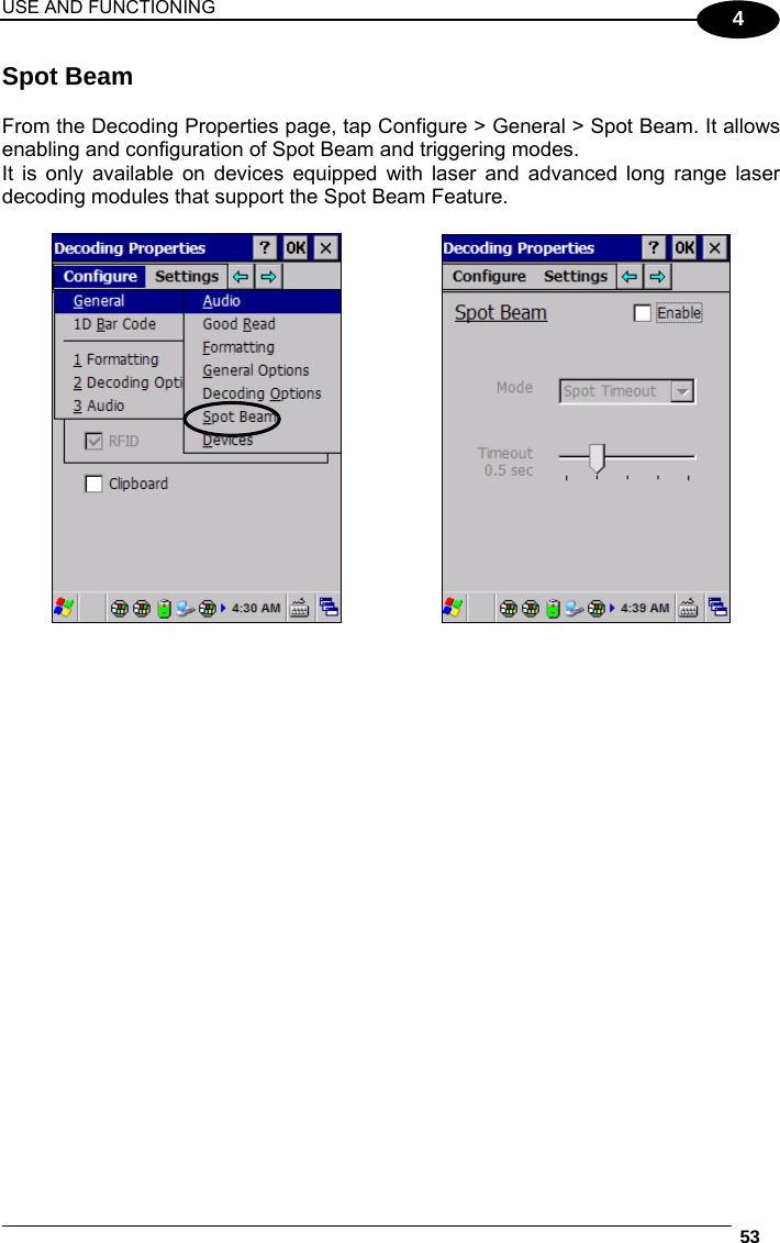
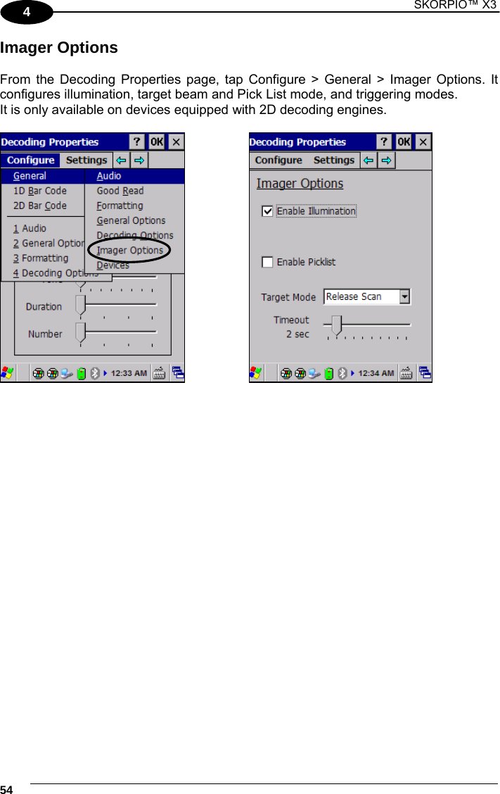
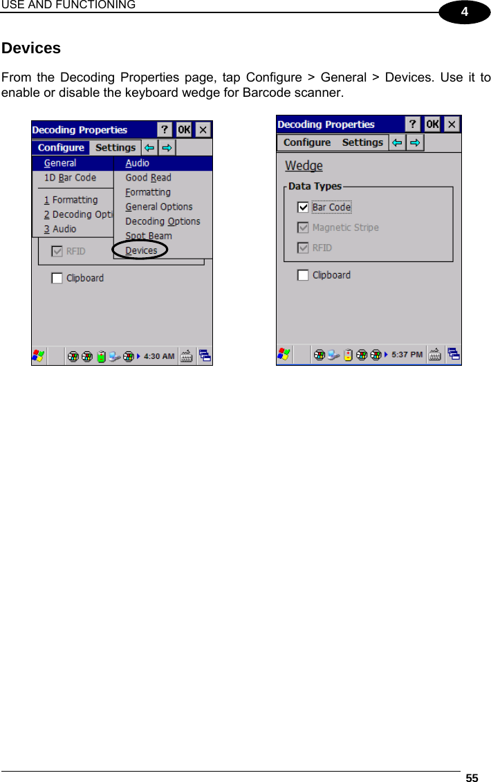
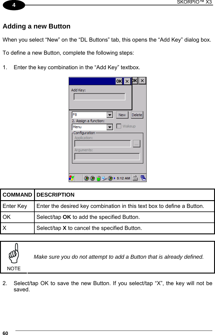
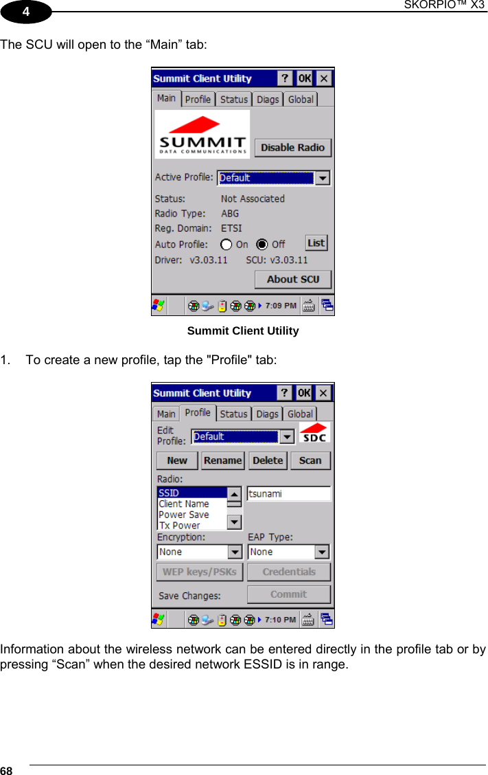
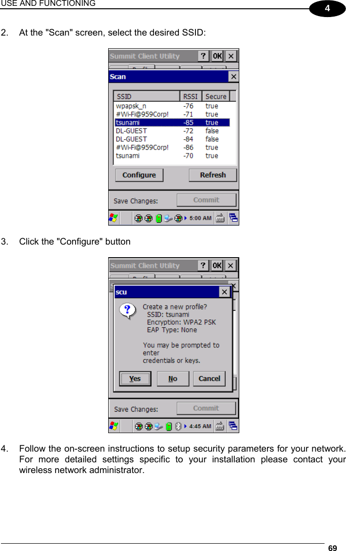
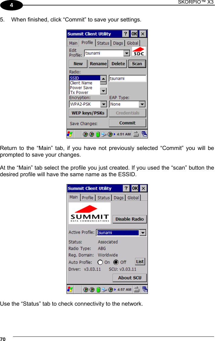
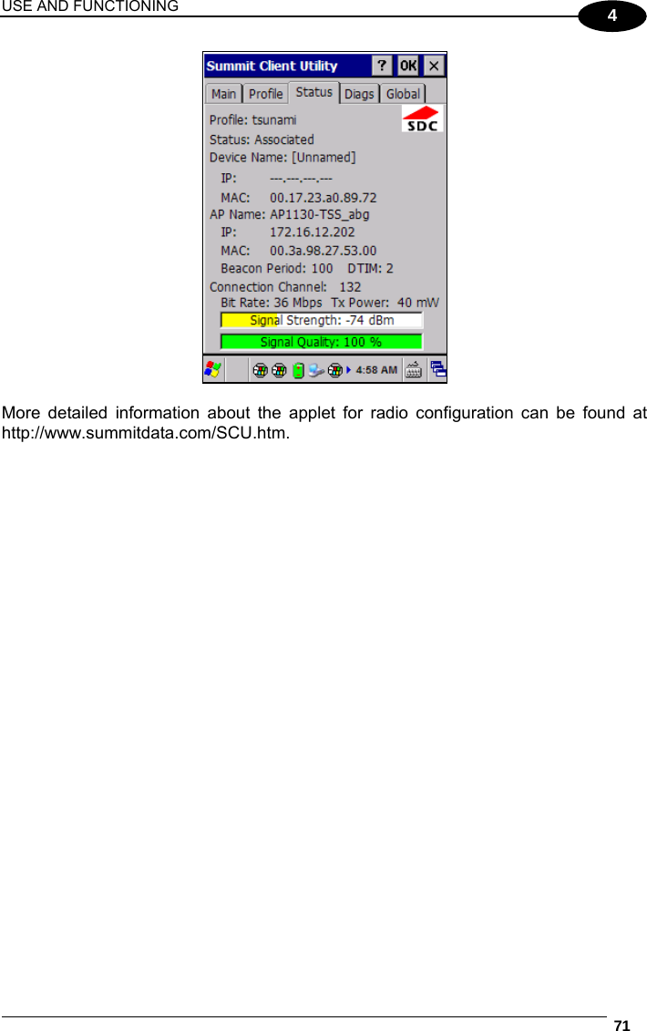
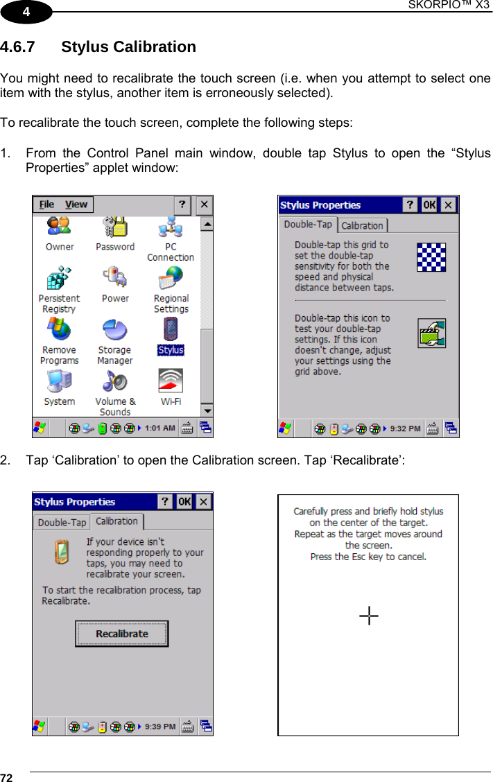
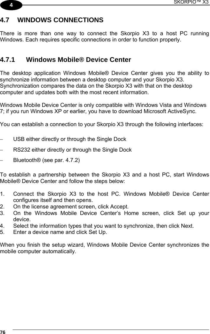
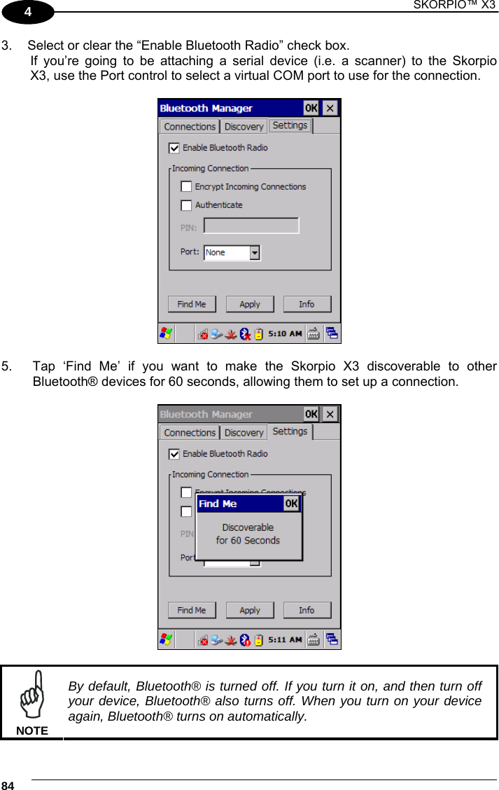
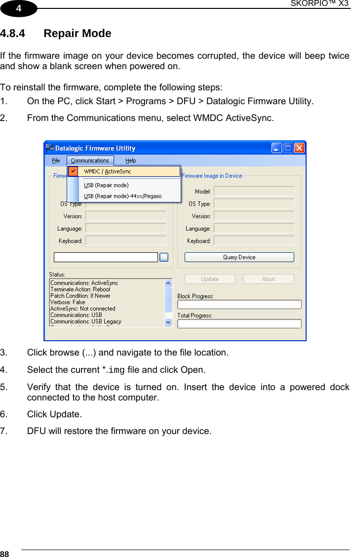
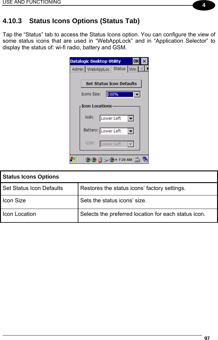
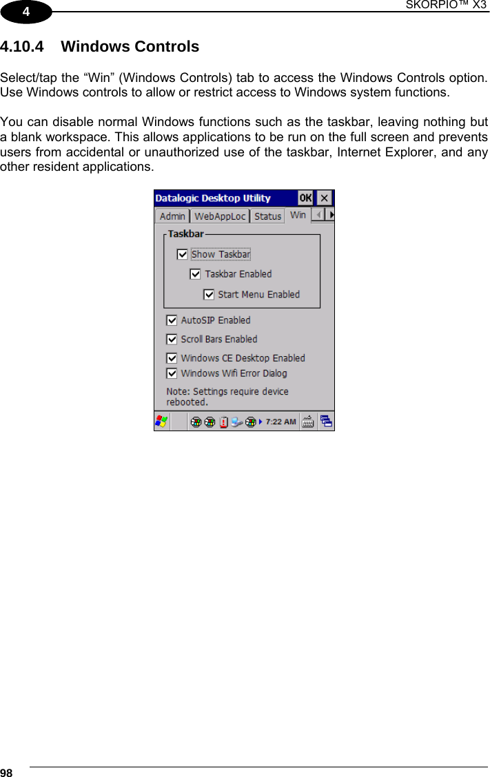
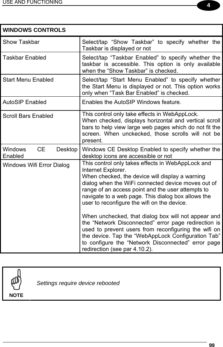
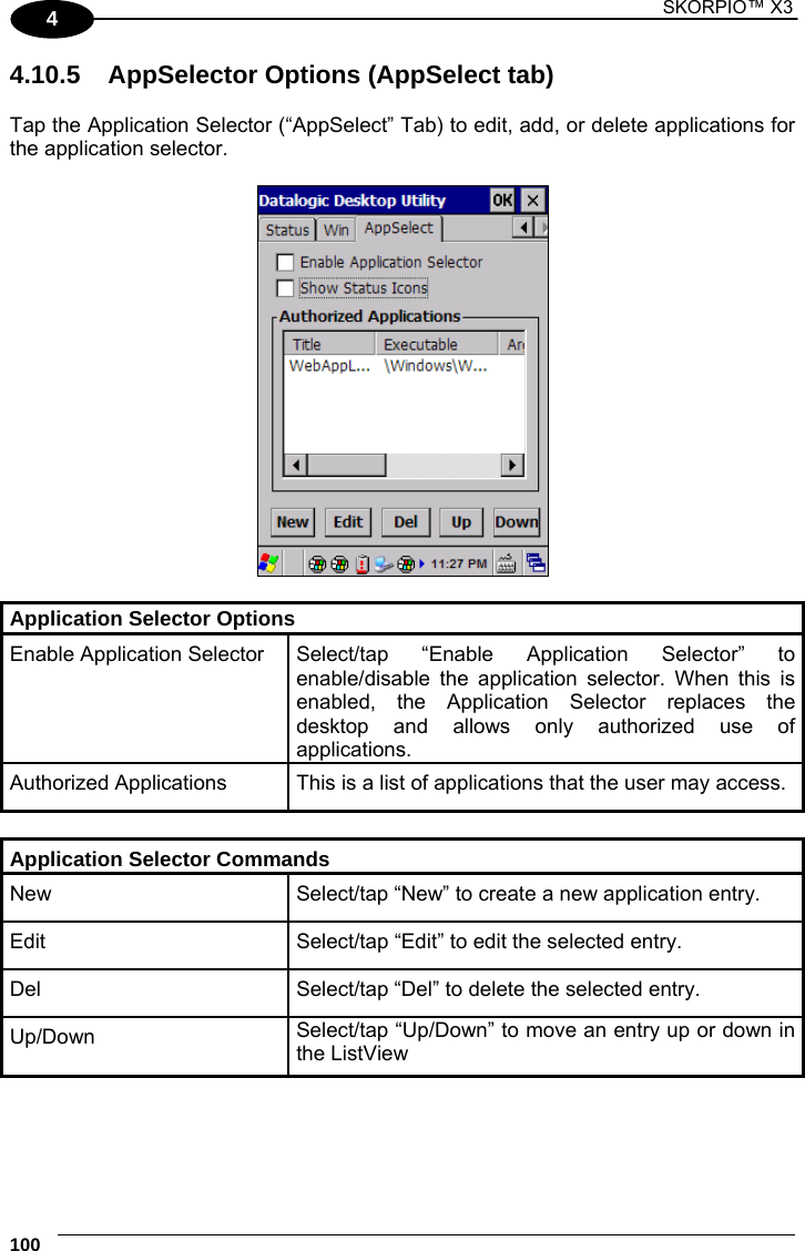
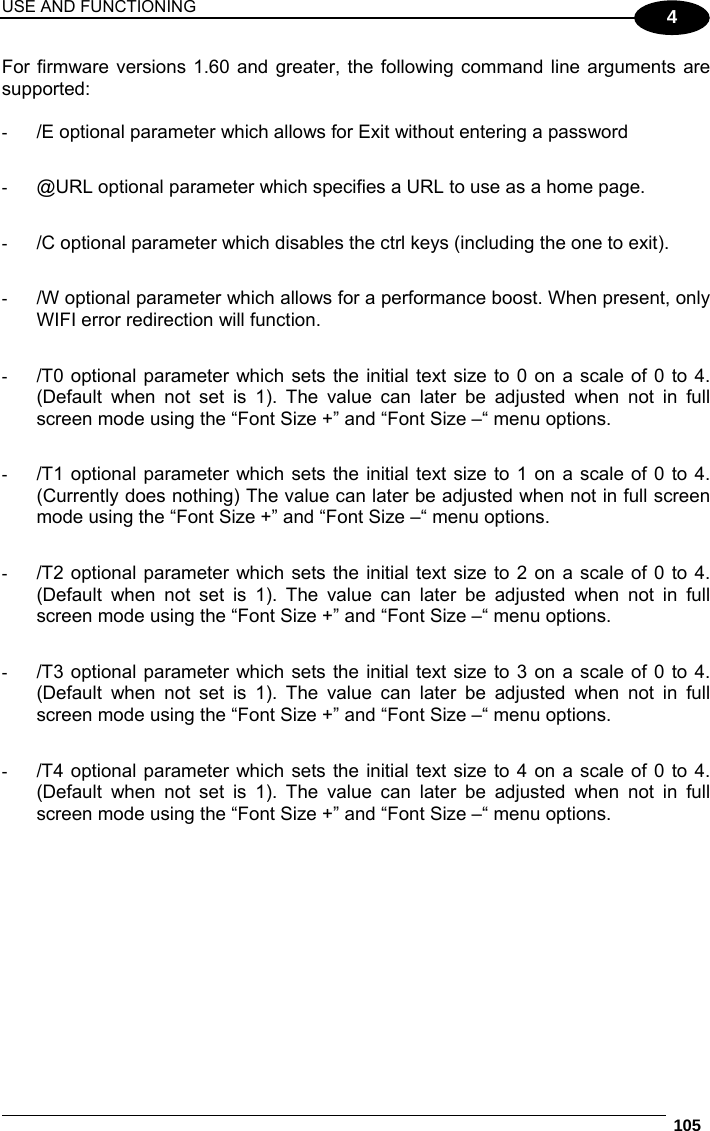
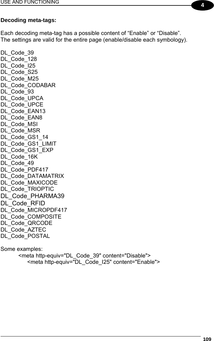
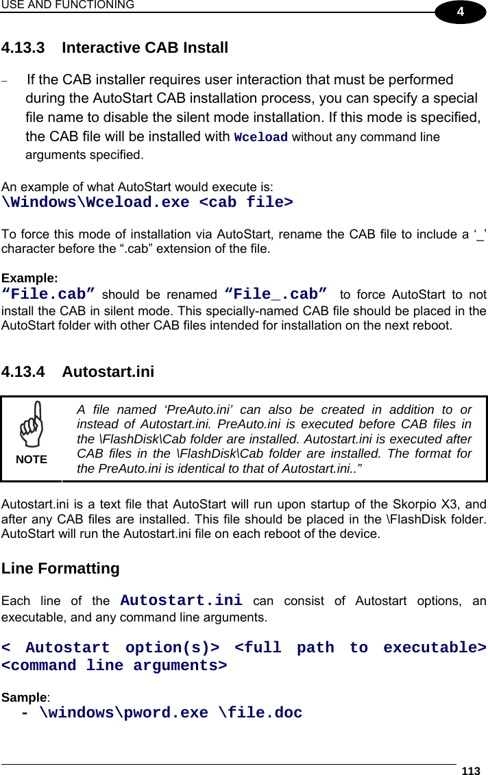
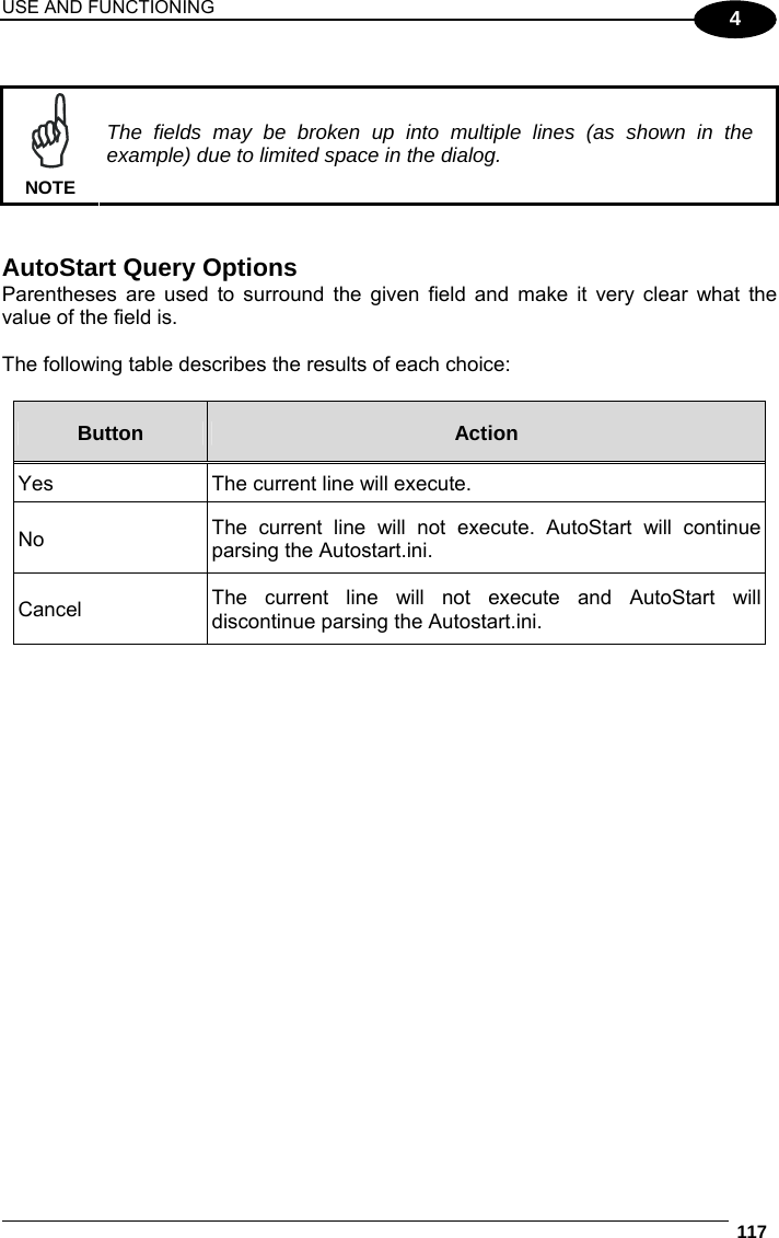
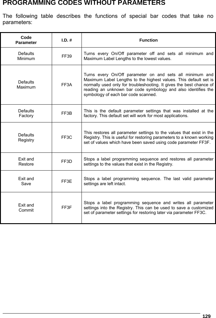
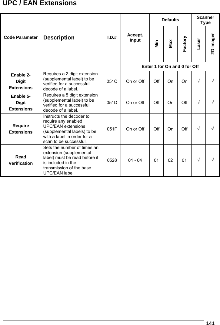
![USE AND FUNCTIONING 29 4 4 USE AND FUNCTIONING The use of the Skorpio X3 depends on the application software loaded. However there are several parameters that can be set and utilities that can be used to perform some basic functions such as data capture, communications, file management, etc 4.1 STARTUP The Skorpio X3 turns on when the battery pack or the external supply is inserted and the ON/OFF Power button is pressed. After the battery pack is installed, use the [ON/OFF] key to turn the mobile computer on and off. As soon as the mobile computer is on, the Windows CE 6.0 desktop will appear on the screen. Wait a few seconds before starting any activity so that the mobile computer completes its startup procedure. Desktop Control Panel Use the stylus (par. 4.1.1) as suggested to select icons and options. The mobile computer goes into power-off (low power with display and keyboard backlight off), when it is not used for more than a programmable timeout, which is defined in the POWER applet of the Control Panel. In this mode it can be awakened (resuming operation) by the [ON/OFF] key.](https://usermanual.wiki/Datalogic-S-r-l/004W.user-manual/User-Guide-1728684-Page-36.png)
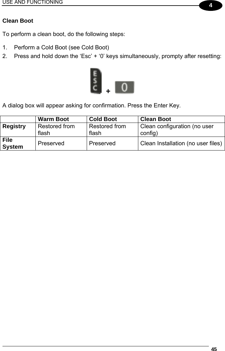
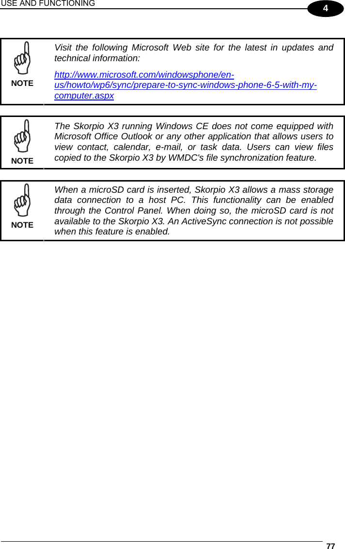
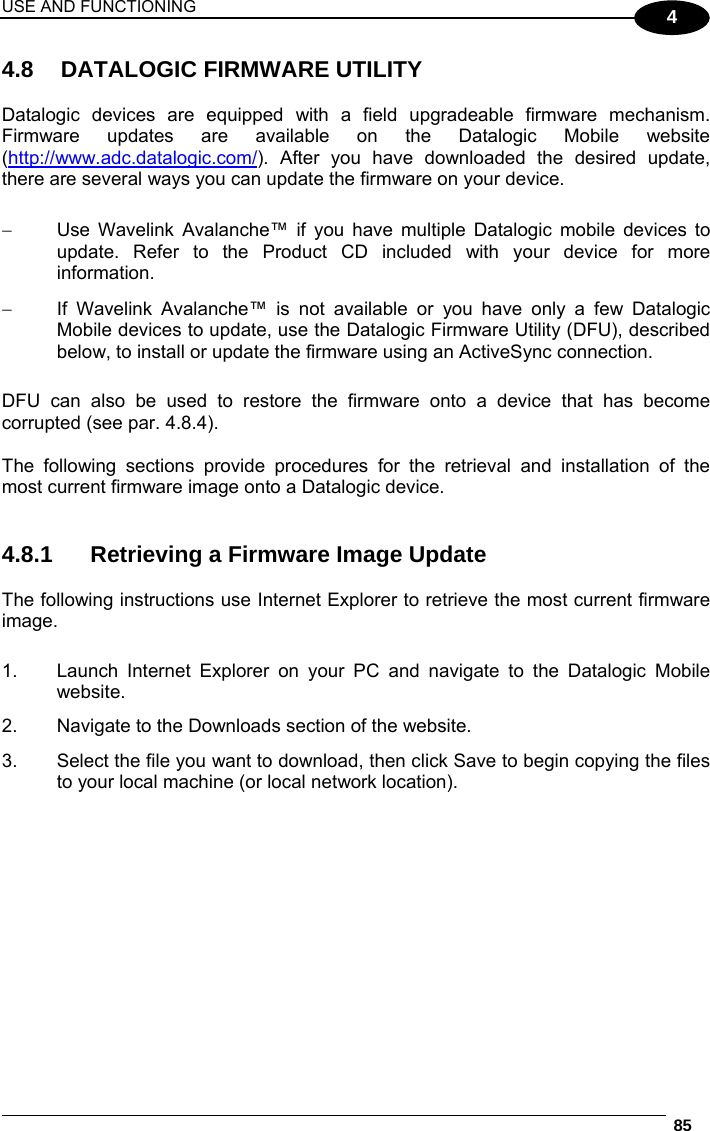

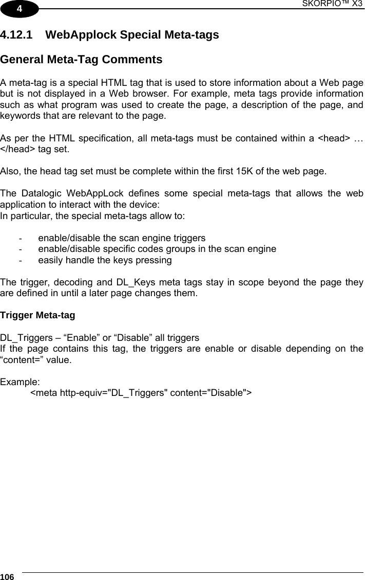
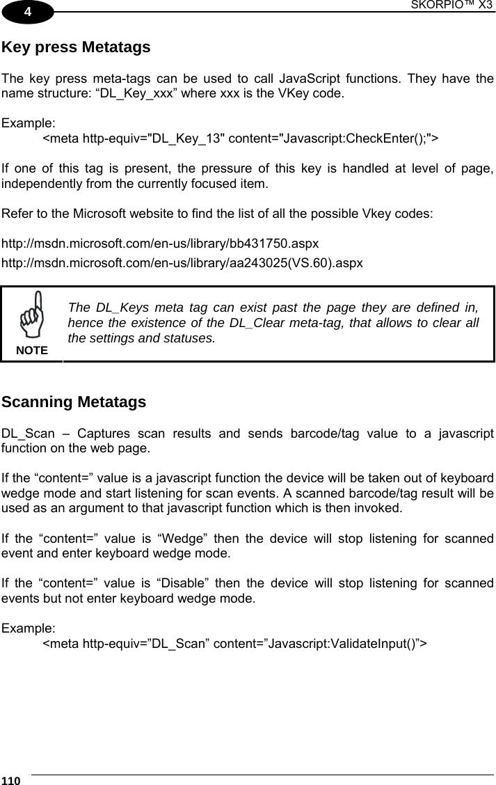
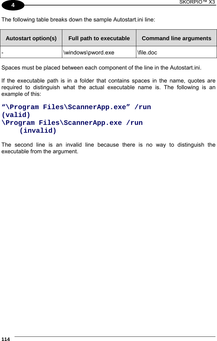
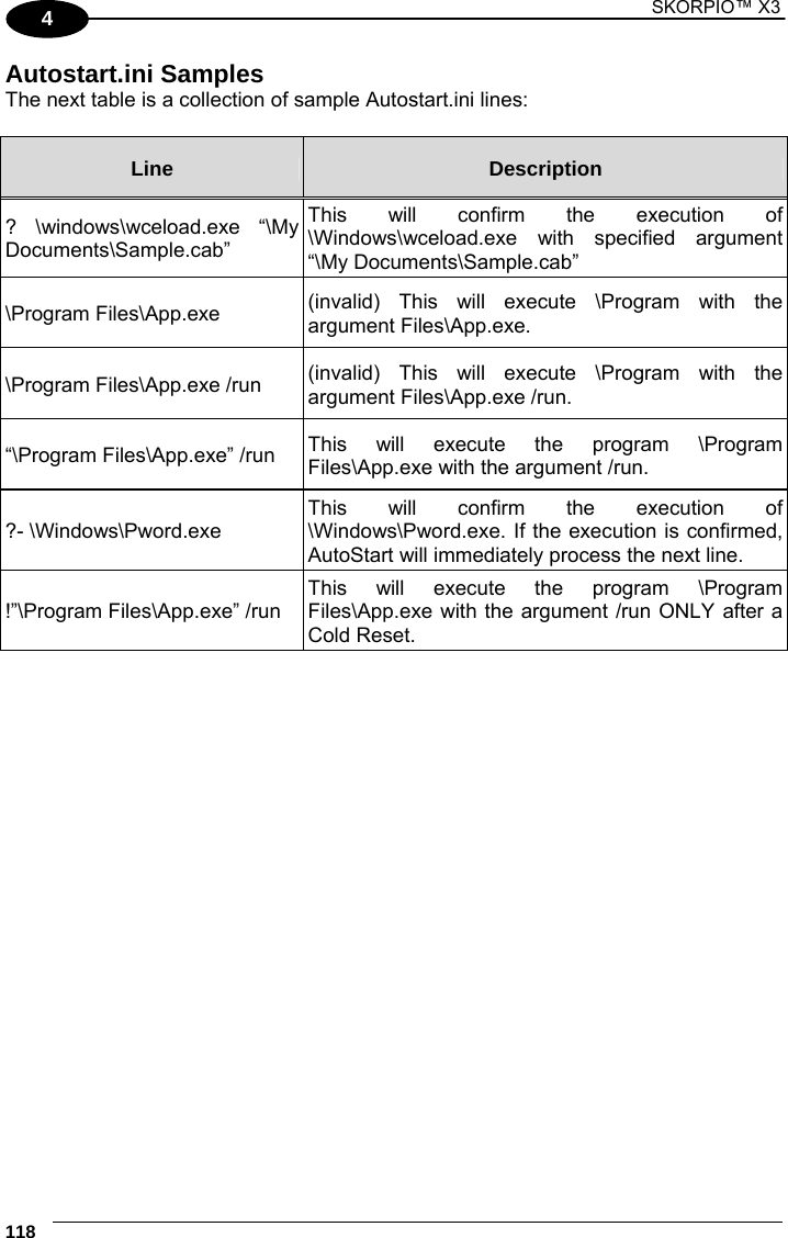
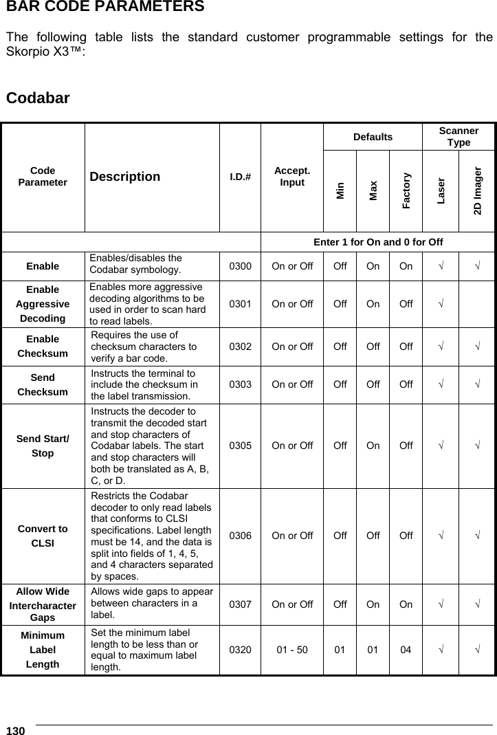
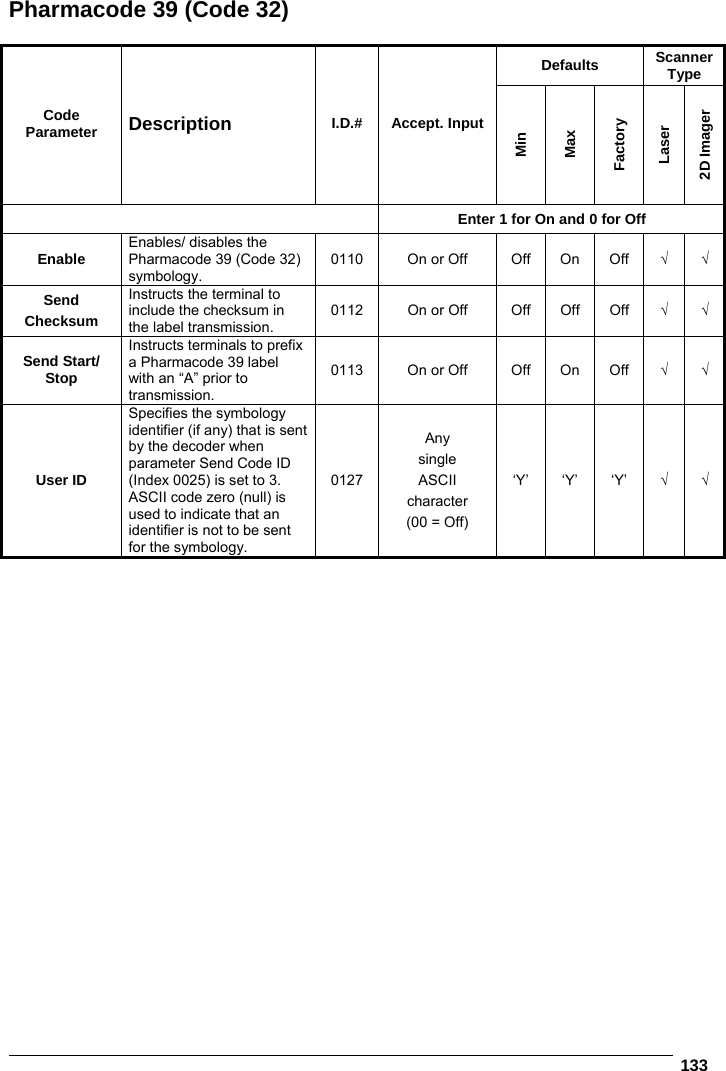
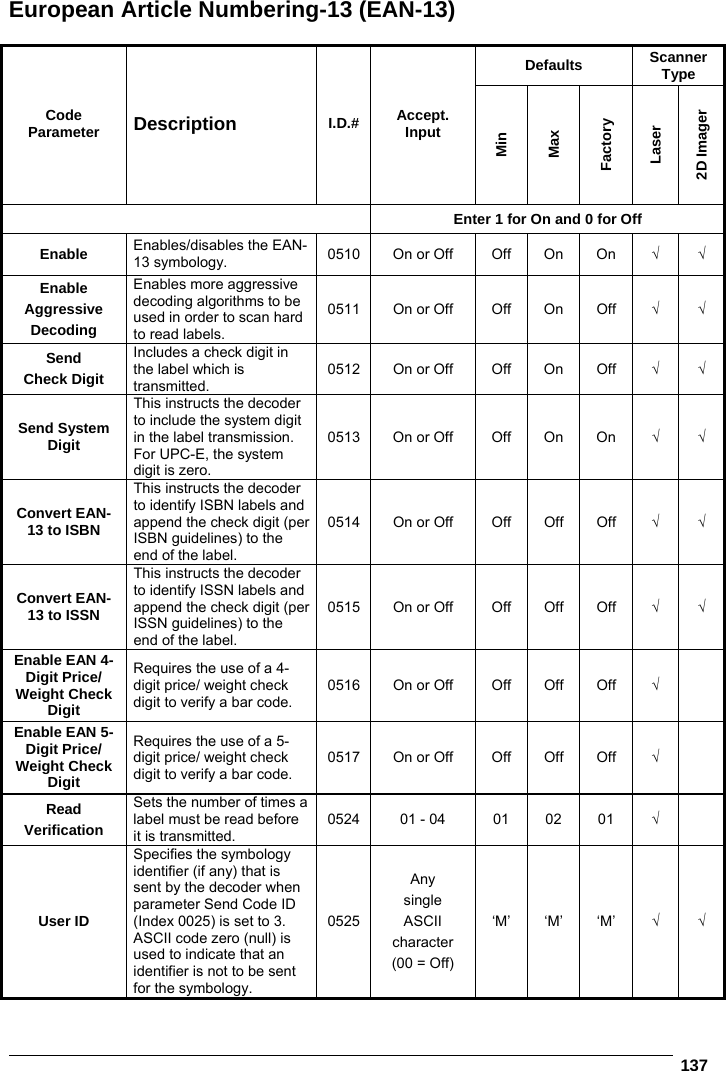
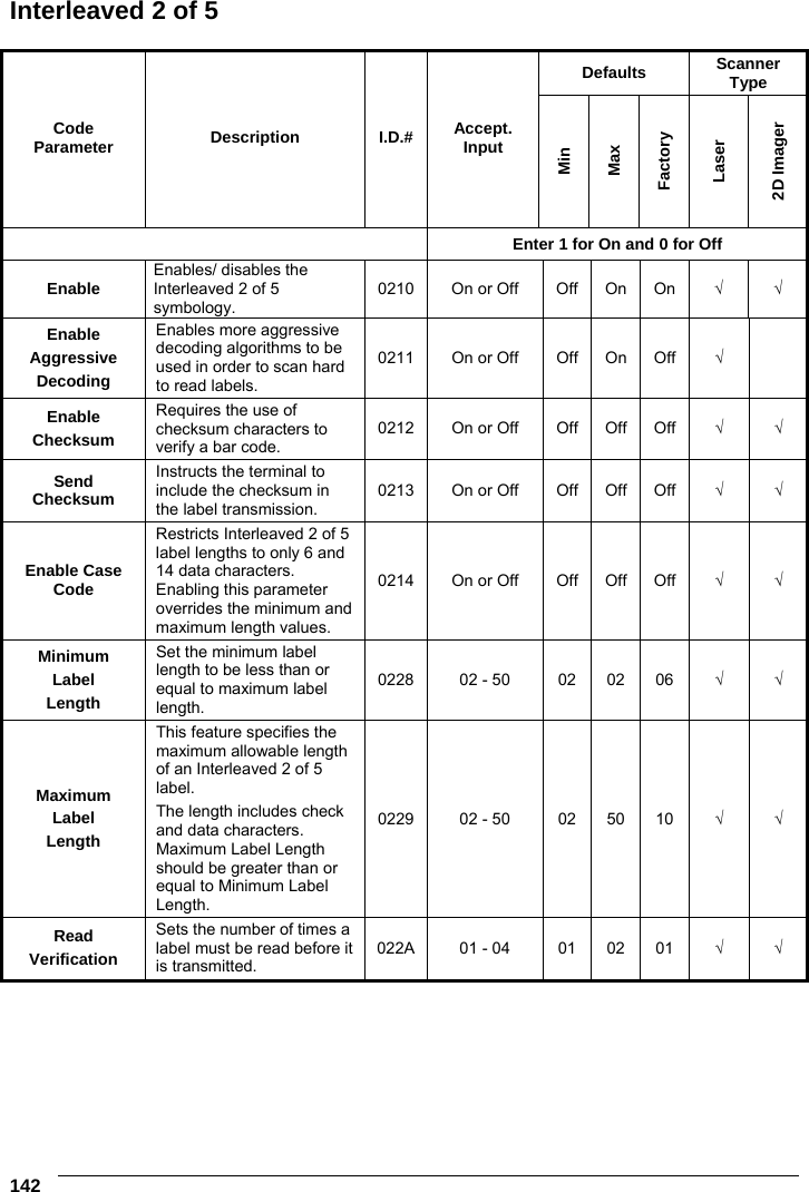
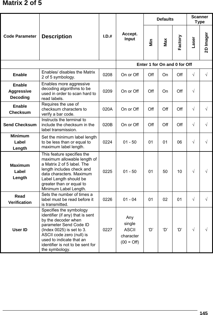
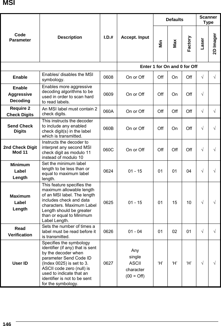
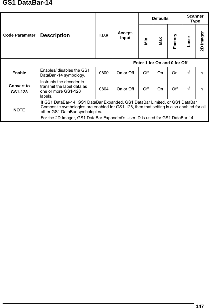
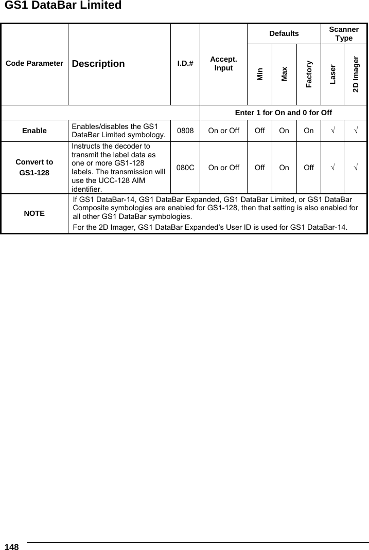
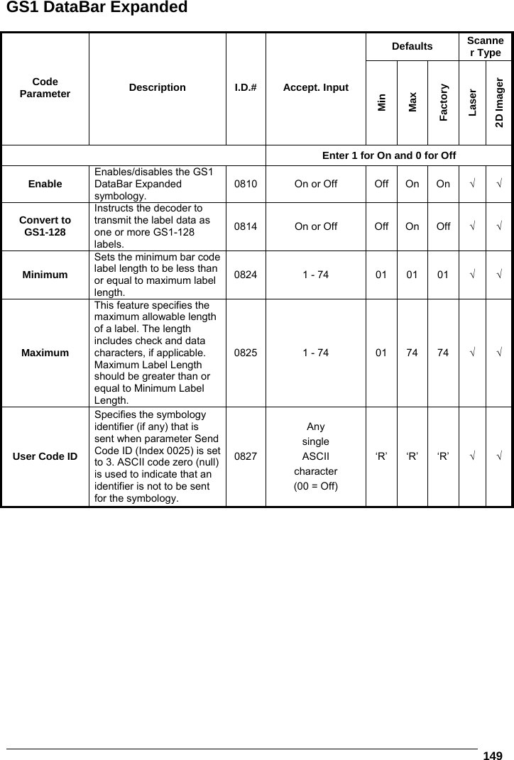
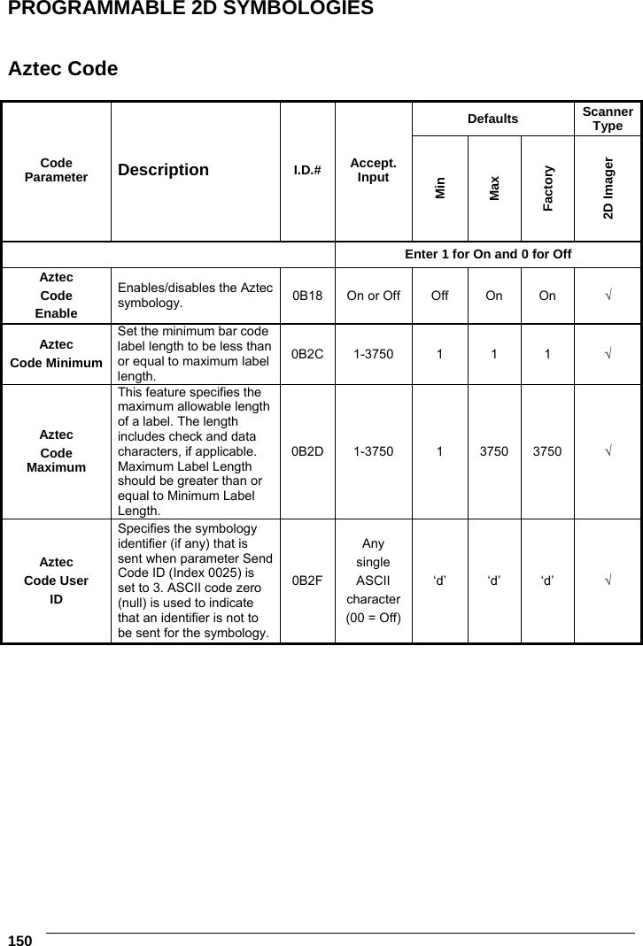

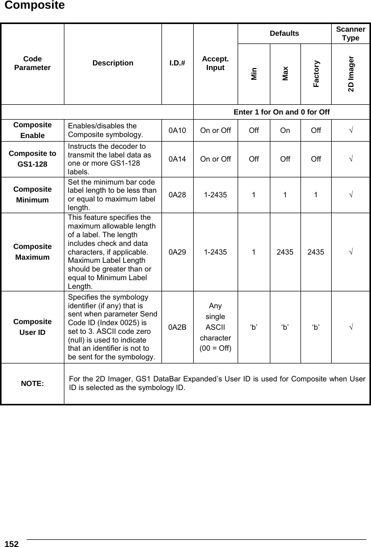
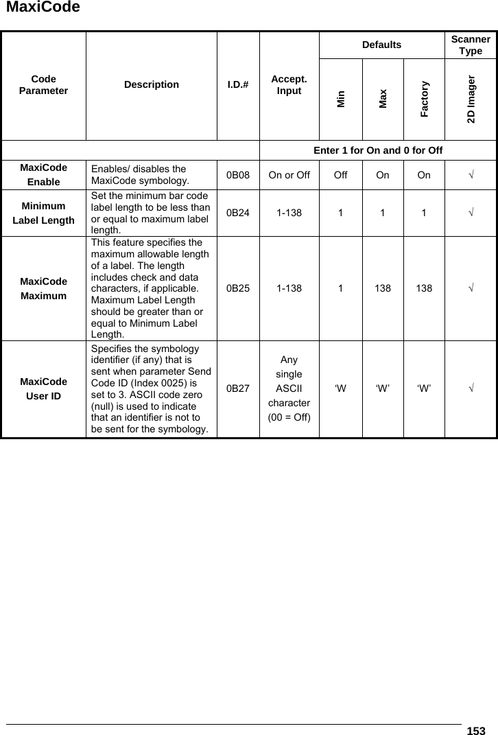
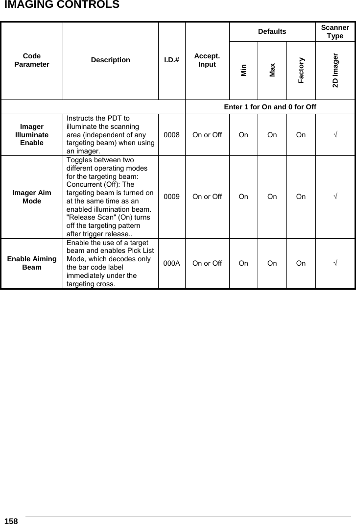
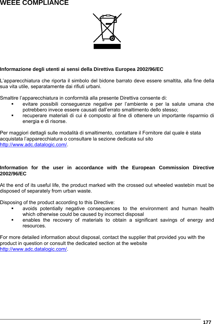
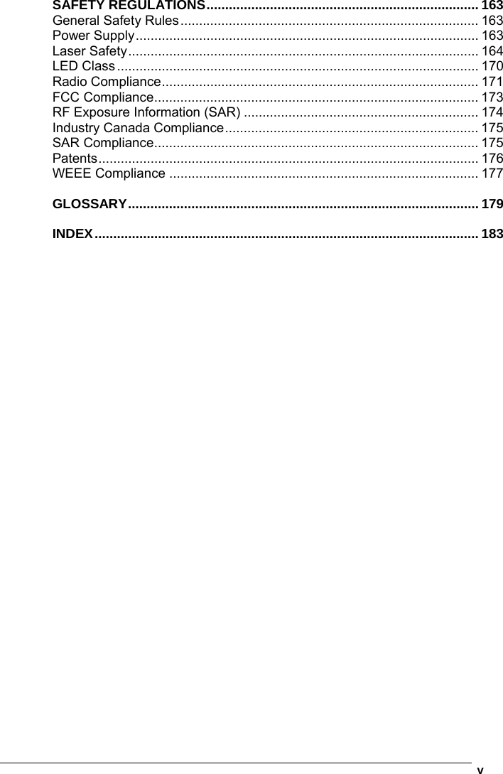
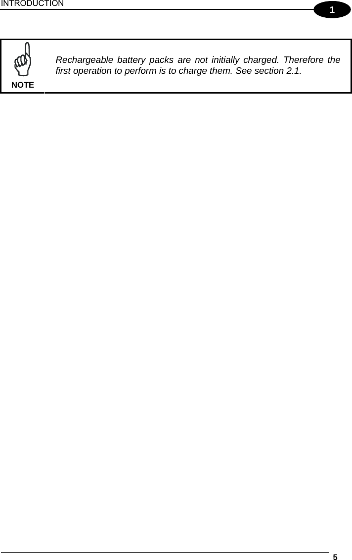
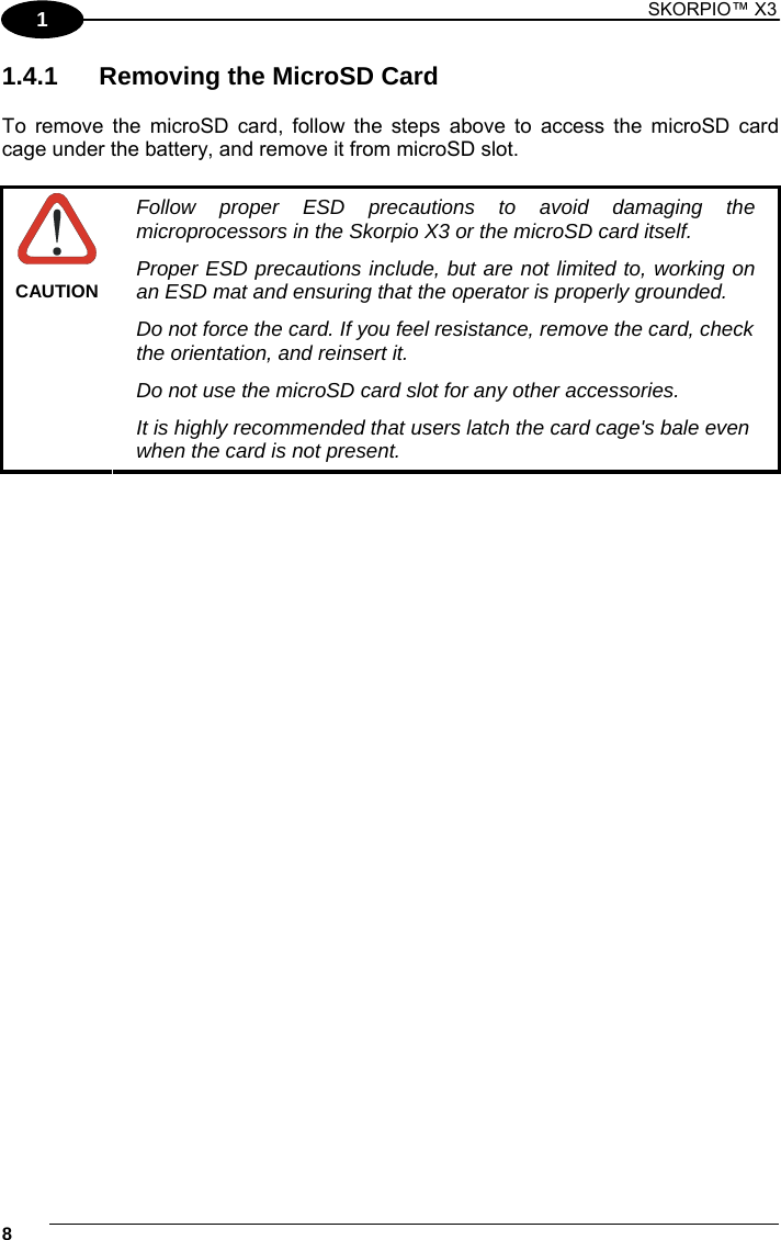
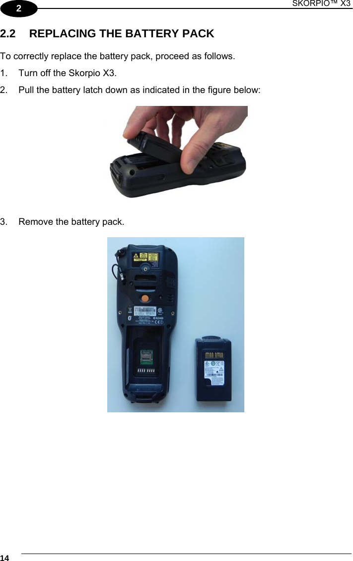
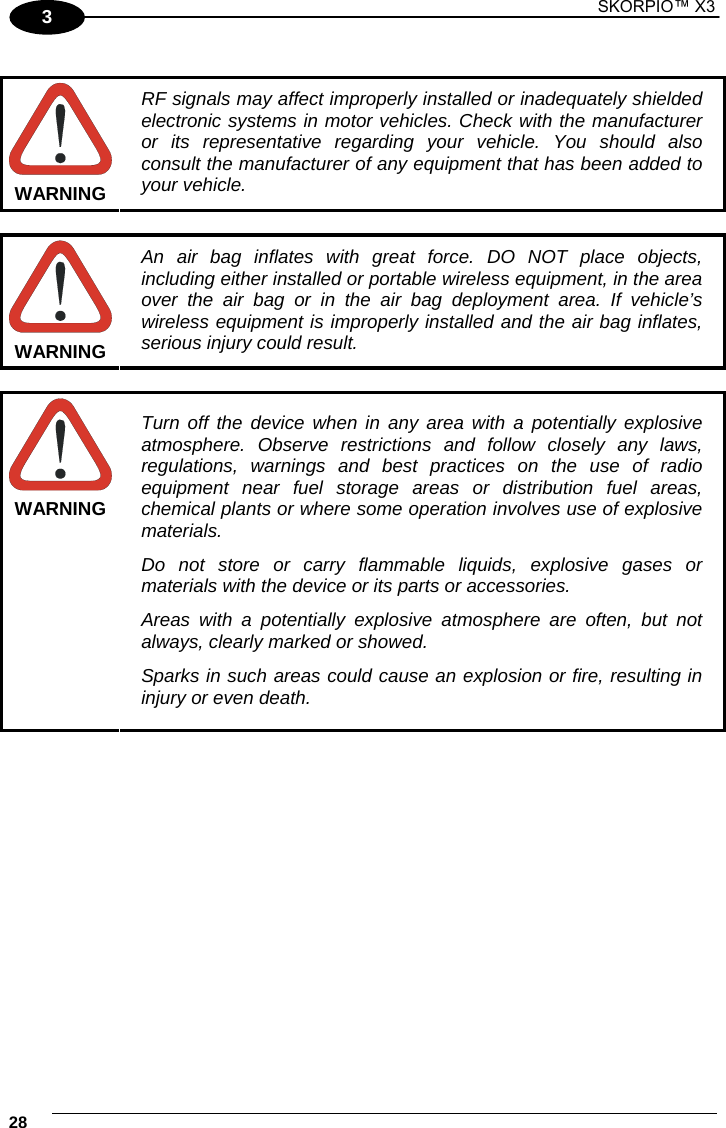
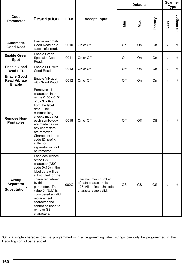
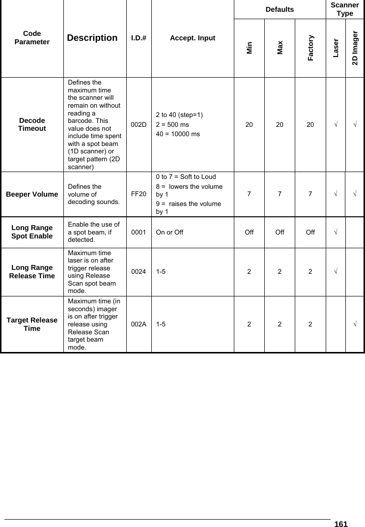
![159 OTHER CONTROLS Defaults Scanner Type Code Parameter Description I.D.# Accept. Input Min Max Factory Laser 2D Imager Enter 1 for On and 0 for Off Enable Label Programming Enables/disables the ability to perform label programming. FF00 On or Off On On On √ √ Send Symbology Identifiers Specifies the symbology identifier (if any) that is sent by the decoder when parameter Send Code ID (Index 0025) is set to 3. ASCII code zero (null) used to indicate an identifier not to be sent for the symbology. 0025 Select symbology identifier to transmit immediately preceding scanned data: 0=None 1=DLM identifier before label: <ID> " " <data> 2=AIM identifier before label: "]" <ID> <modifier> <data> 3=User defined identifier before label: <ID> <data> 4=DLM identifier after label: <data> " " <ID> 5=AIM identifier after label: <data> "]" <ID> <modifier> 6=User defined identifier after label: <data> <ID> 00 01 00 √ √ Label Prefix Character string sent immediately prior to symbology identifier (0=None). 0026 A string of Unicode characters. NUL NUL NUL √ √ Label Suffix* Character string sent immediately after final character in data (0=None). 0027 A string of Unicode characters. CR+LF CR+LF CR+LF √ √ Label Separator Character string sent after each string in a sample where multiple strings exist. 0028 Any single ASCII character (00 = Off). CR CR CR √ √ Only a single character can be programmed with a programming label; strings can only be programmed in the Decoding control panel applet.](https://usermanual.wiki/Datalogic-S-r-l/004W.user-manual/User-Guide-1728684-Page-166.png)
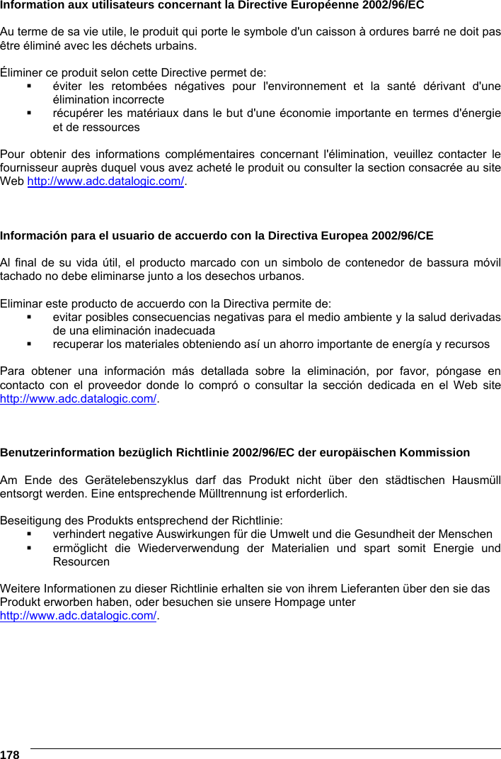
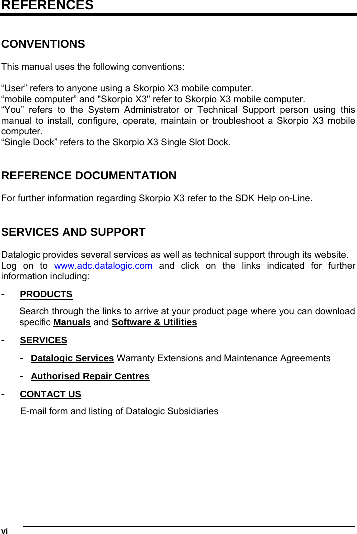
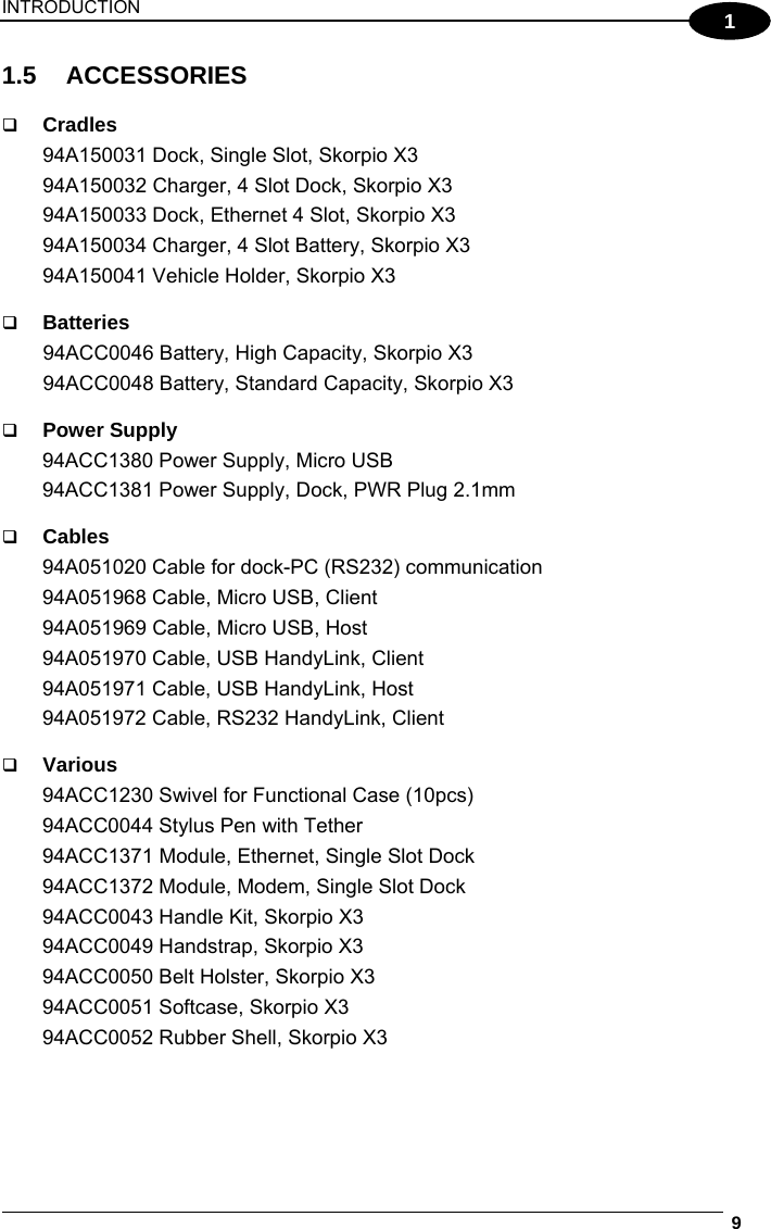
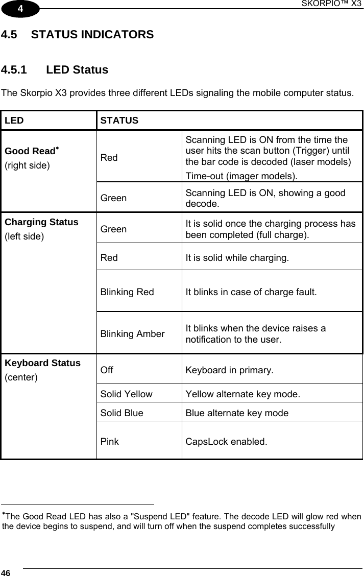
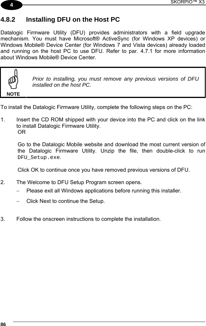
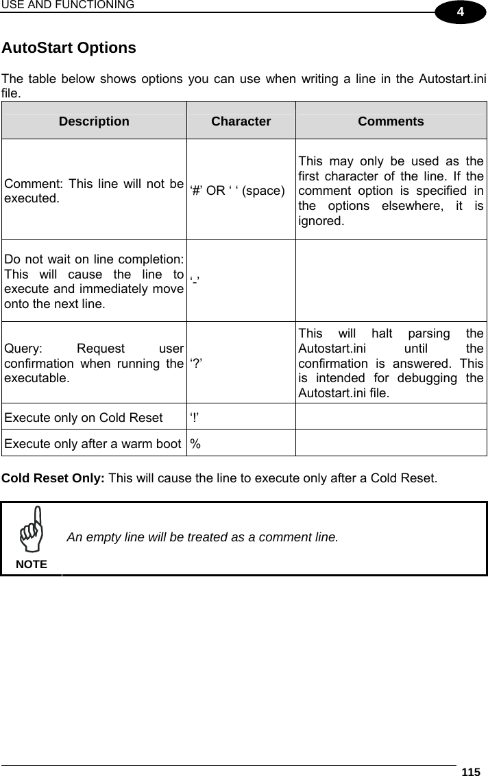
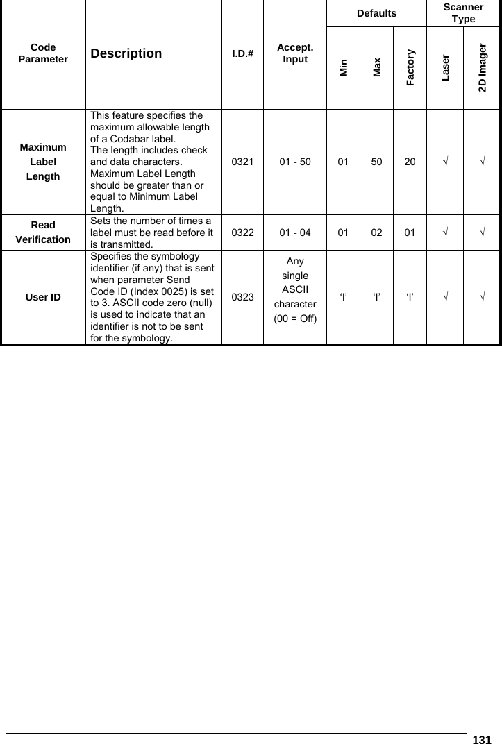
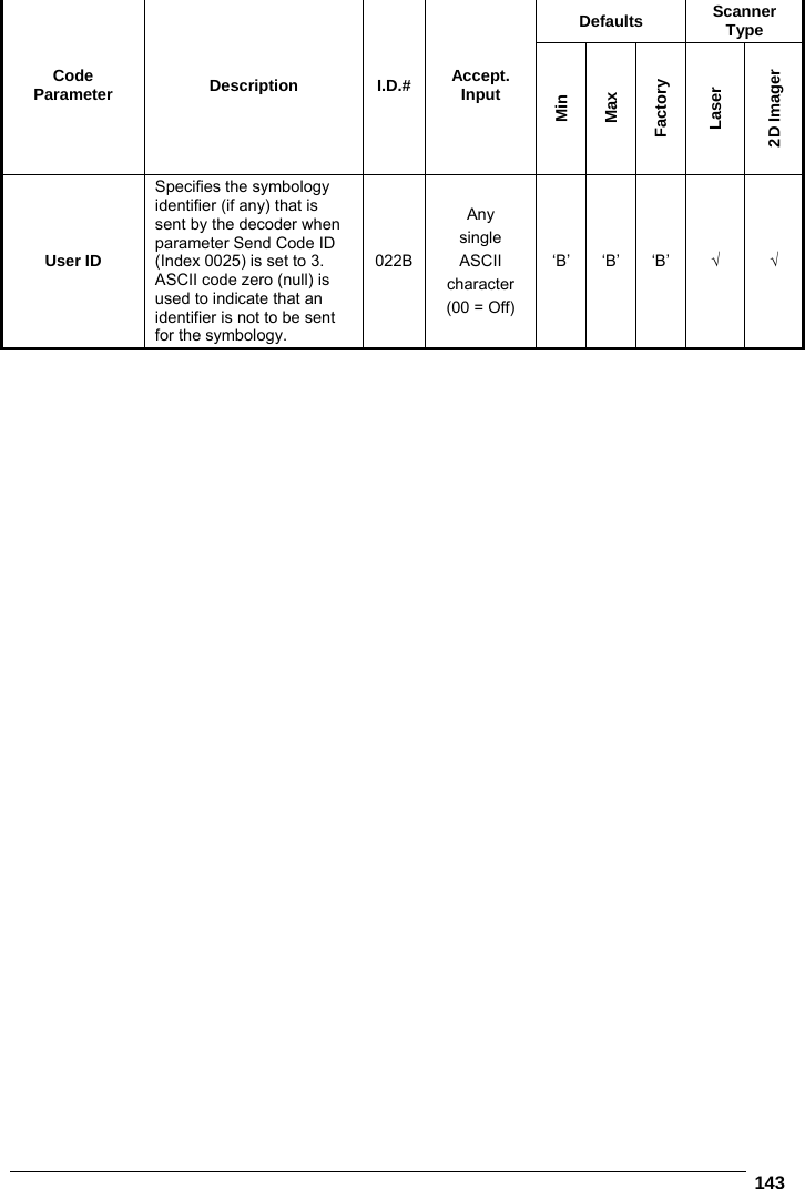
![175 INDUSTRY CANADA COMPLIANCE This device complies with Industry Canada license-exempt RSS standard(s). Operation is subject to the following two conditions: (1) this device may not cause interference, and (2) this device must accept any interference, including interference that may cause undesired operation of the device. This Class B digital apparatus complies with Canadian ICES-003. Cet appareil numérique de la classe B est conforme à la norme NMB-003 du Canada. This device and its antenna(s) must not be co-located or operating in conjunction with any other antenna or transmitter. The County Code Selection feature is disabled for products marketed in the US/Canada. This EUT is compliant with SAR for general population/uncontrolled exposure limits in IC RSS-102 and had been tested in accordance with the measurement methods and procedures specified in IEEE 1528. This equipment should be installed and operated with minimum distance 1,5cm between the radiator & your body. Le présent appareil est conforme aux CNR d'Industrie Canada applicables aux appareils radio exempts de licence. L'exploitation est autorisée aux deux conditions suivantes : (1) l'appareil ne doit pas produire de brouillage, et (2) l'utilisateur de l'appareil doit accepter tout brouillage radioélectrique subi, même si le brouillage est susceptible d'en compromettre le fonctionnement. SAR COMPLIANCE This product has been tested and found to comply with the following standards: - For the used worst case positions, the portable device Skorpio X3 from Datalogic (FCC ID: U4G0060; contains FCC ID: U4G004W) is in compliance with the IC RSS 102 Issue 4 [RSS 102] and Federal Communications Commission (FCC) Guidelines [OET 65] for uncontrolled exposure. SAR assessment in body worn was conducted with a distance of 15 mm between the housing of the handheld and the flat phantom. - EN 62311:2008: assessment of electronic and electrical equipment related to human exposure restrictions for electromagnetic fields (0 Hz – 300 GHz).](https://usermanual.wiki/Datalogic-S-r-l/004W.user-manual/User-Guide-1728684-Page-182.png)