Datalogic S r l 0073 Mobile Computer User Manual Chap1
Datalogic ADC S.r.l. Mobile Computer Chap1
UserManual.wiki
>
Datalogic S r l
>
0073 User Manual
User Manual
Navigation menu
Upload a User Manual
Namespaces
Wiki Guide
HTML
PDF
Info
Views
User Manual
Discussion / Help
Navigation
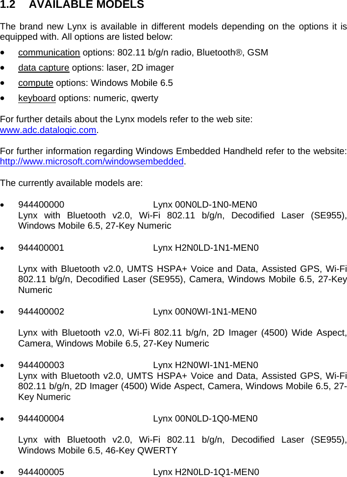


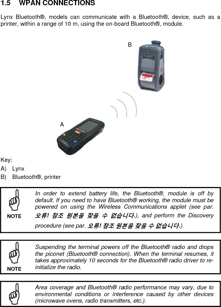

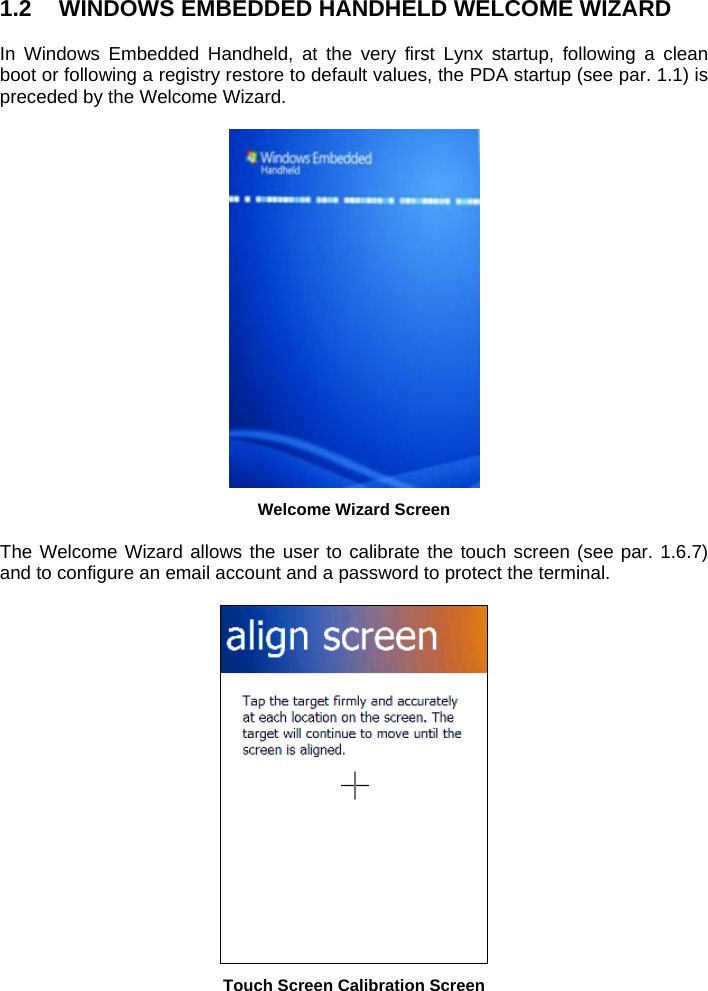
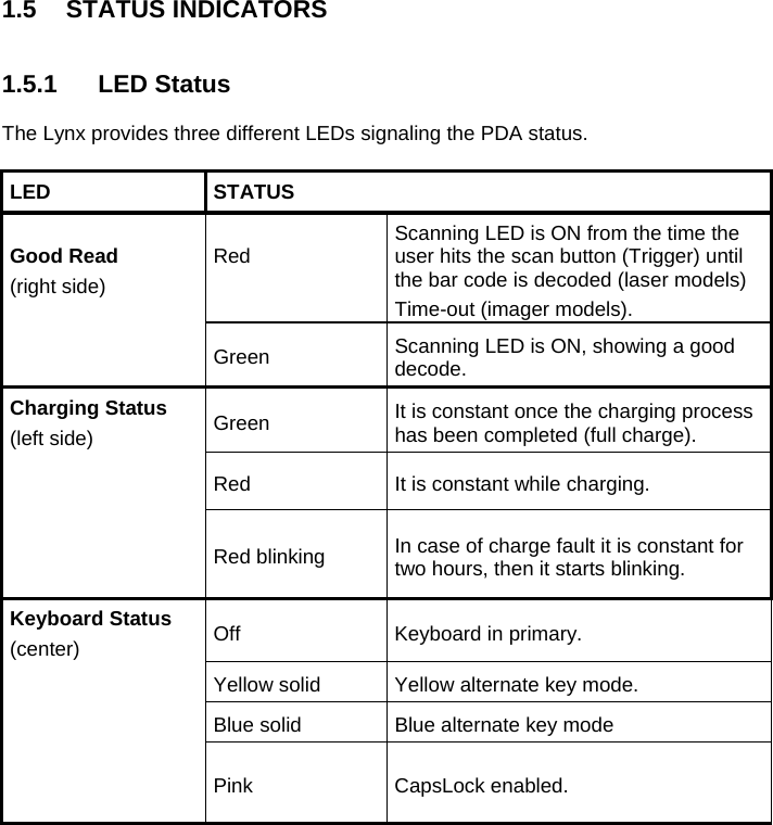
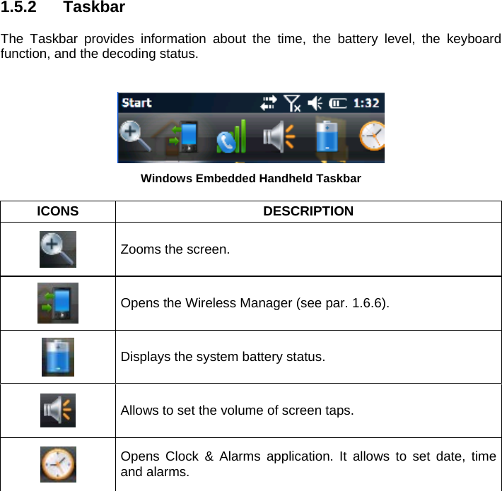
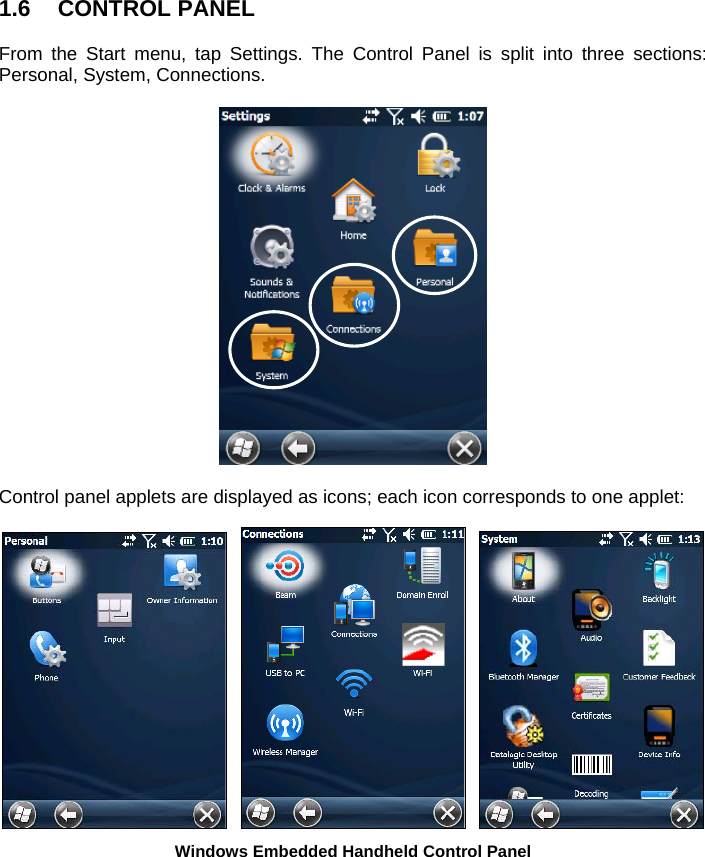
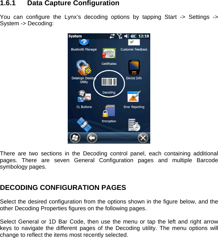
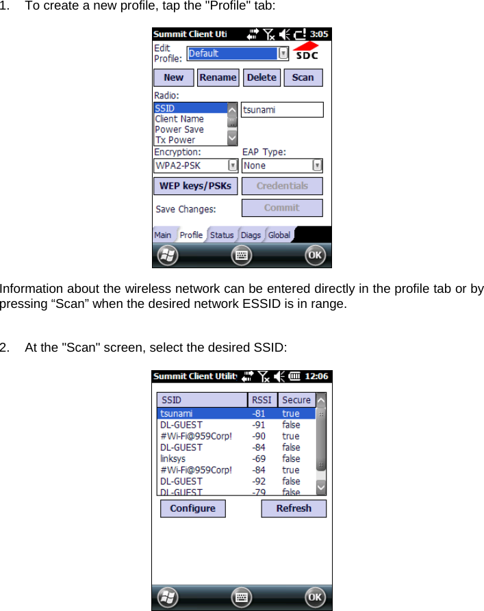
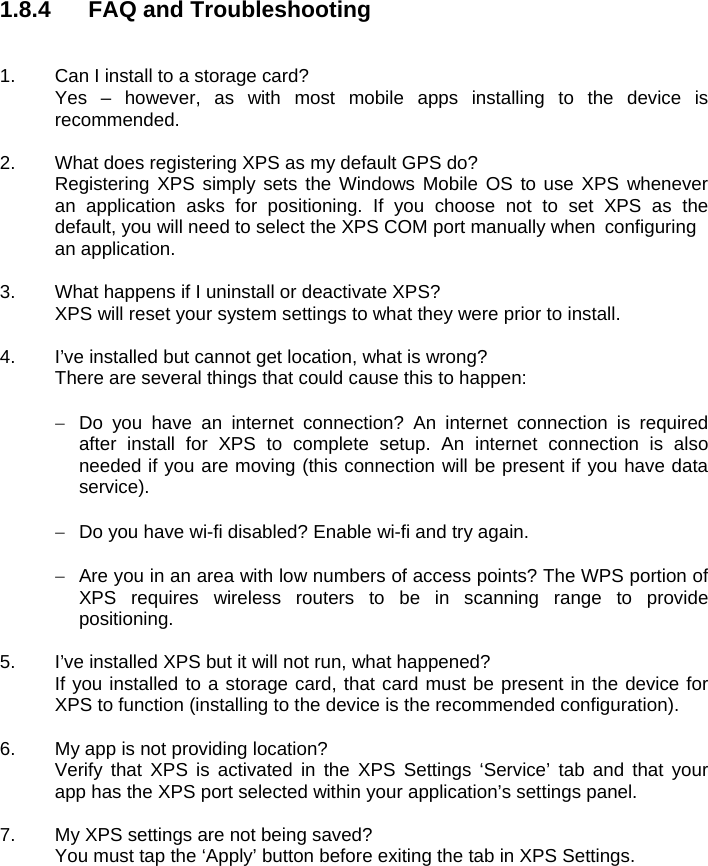
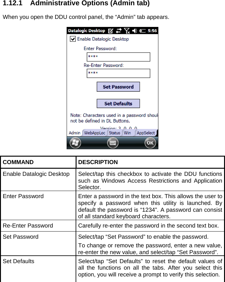
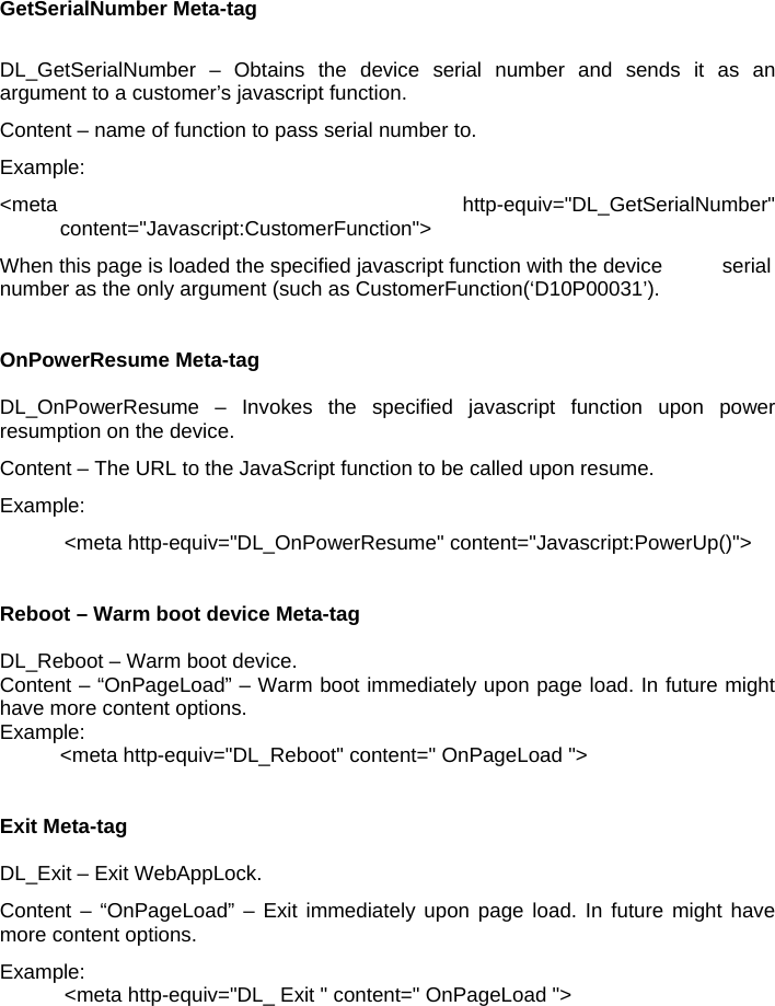
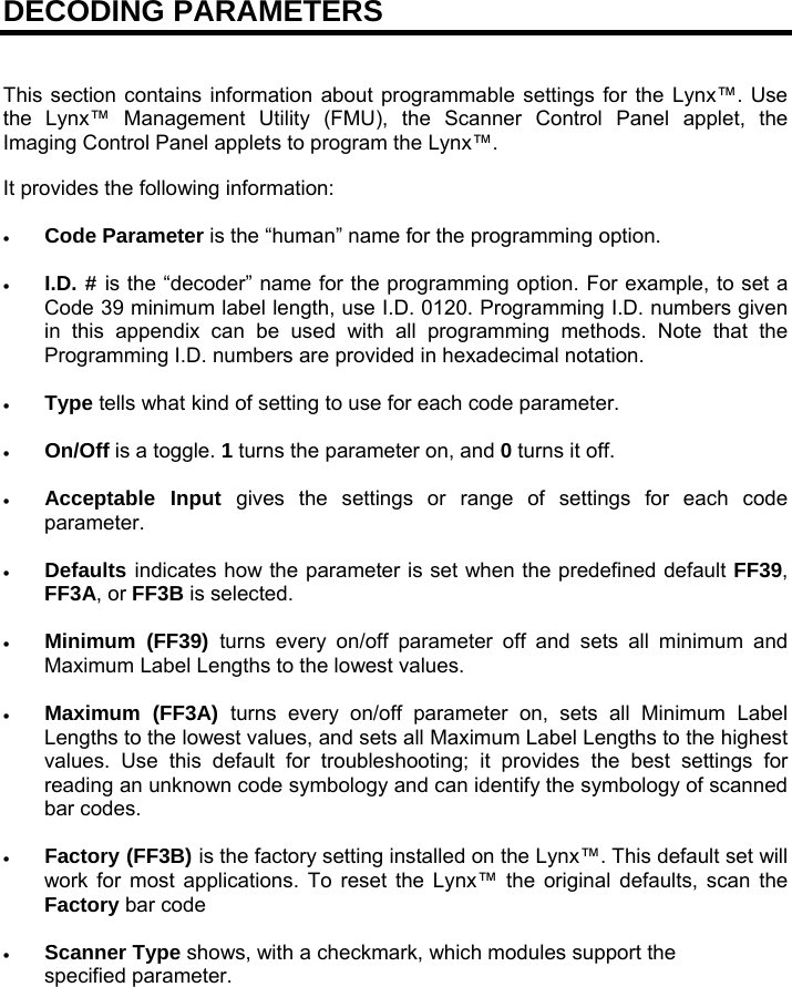
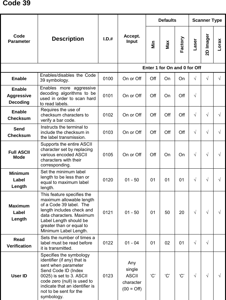
![4. USE AND FUNCTIONING The use of the Lynx depends on the application software loaded. However there are several parameters that can be set and utilities that can be used to perform some basic functions such as data capture, communications, file management, etc 1.1 STARTUP The Lynx turns on when the battery pack or the external supply is inserted and the ON/OFF Power button is pressed. After the battery pack is installed, use the [ON/OFF] key to turn the PDA on and off. As soon as the PDA is on, the Windows Embedded Handheld 6.5 desktop configuration will appear on the screen. Wait a few seconds before starting any activity so that the PDA completes its startup procedure. Today Screen Start Menu Use the stylus (par. 1.1.1) as suggested to select icons and options. The PDA goes into power-off (low power with display and keyboard backlight off), when it is no longer used for more than a programmable timeout, which is defined in the POWER applet of the Control Panel. In this mode it can be awakened (resuming operation) by the [ON/OFF] key.](https://usermanual.wiki/Datalogic-S-r-l/0073/User-Guide-1825795-Page-34.png)

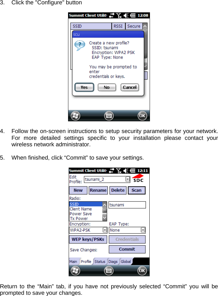
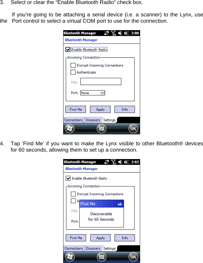
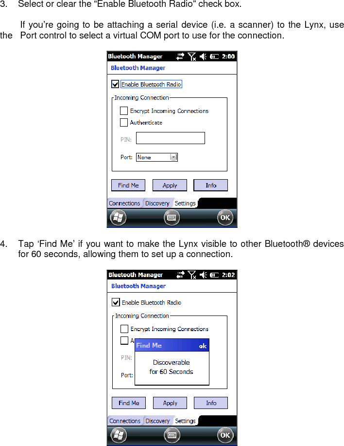

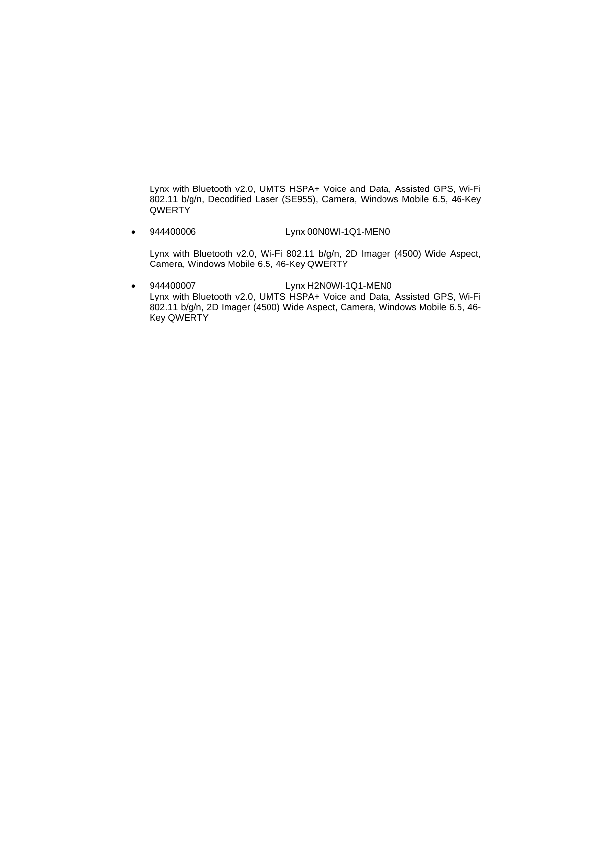
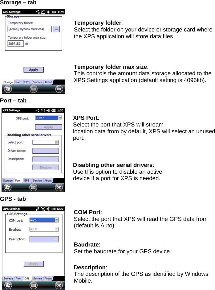
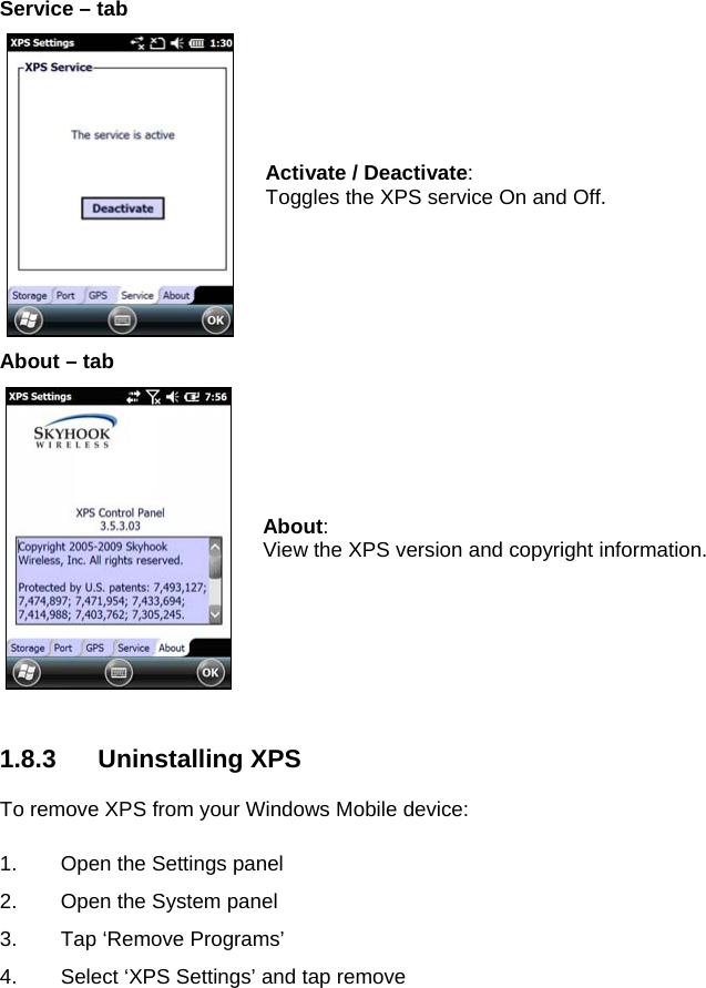
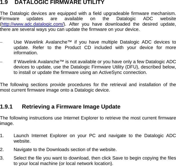
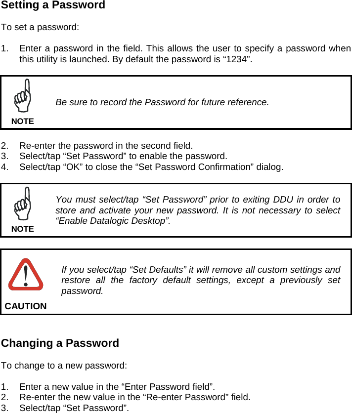
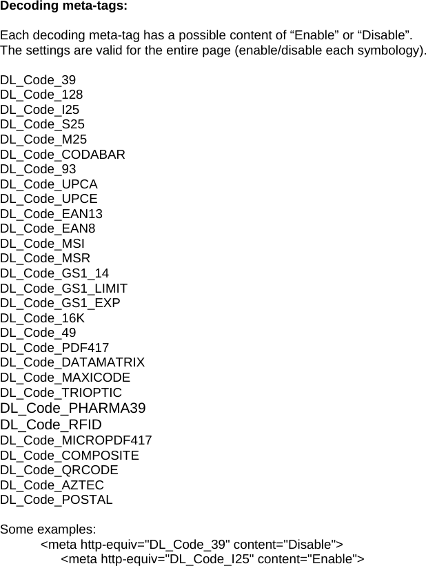
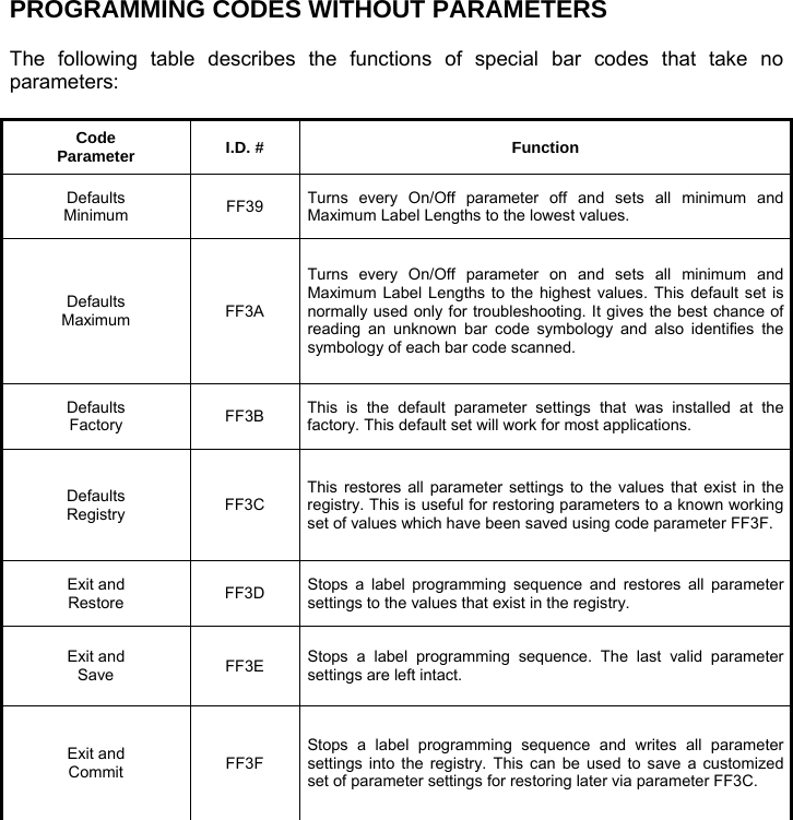
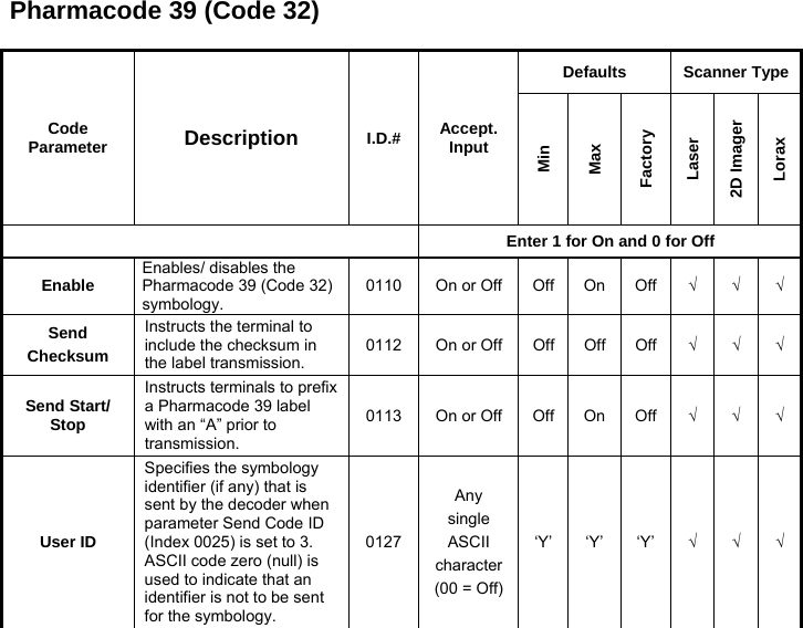
![1.8 SKYHOOK° XPS SETTINGS 1.8.1 XPS - Virtual GPS for Windows Mobile Skyhook synthesizes data from Skyhook's Wi-Fi Positioning System (WPS), GPS satellites and cell towers with advanced hybrid positioning algorithms combining as much as possible to build a composite position and to provide the best possible location available in any environment. XPS Program Icon 1.8.2 Configuring XPS When the XPS Settings installation has completed, the settings panel will display five tabs that can be used to configure your device. The default settings should be correct for most applications. NOTE You MUST click [Apply] when changing settings on each tab. NOTE](https://usermanual.wiki/Datalogic-S-r-l/0073/User-Guide-1825795-Page-86.png)
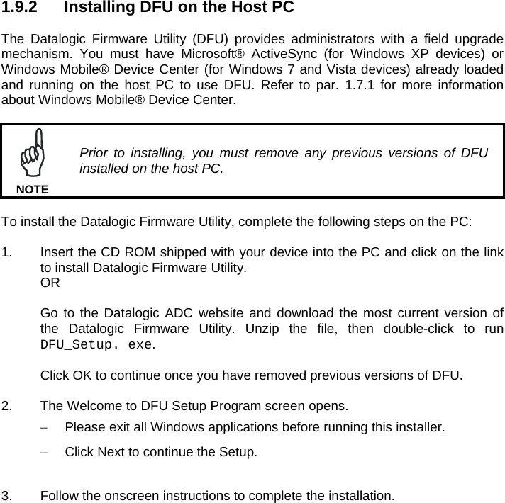
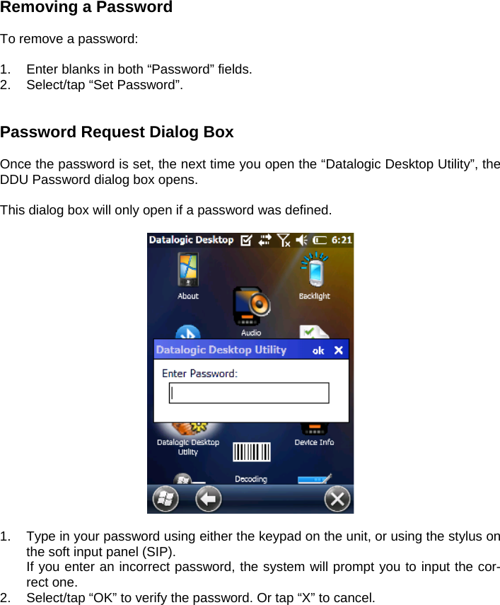
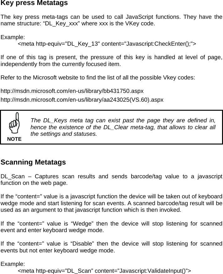
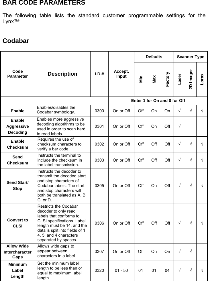
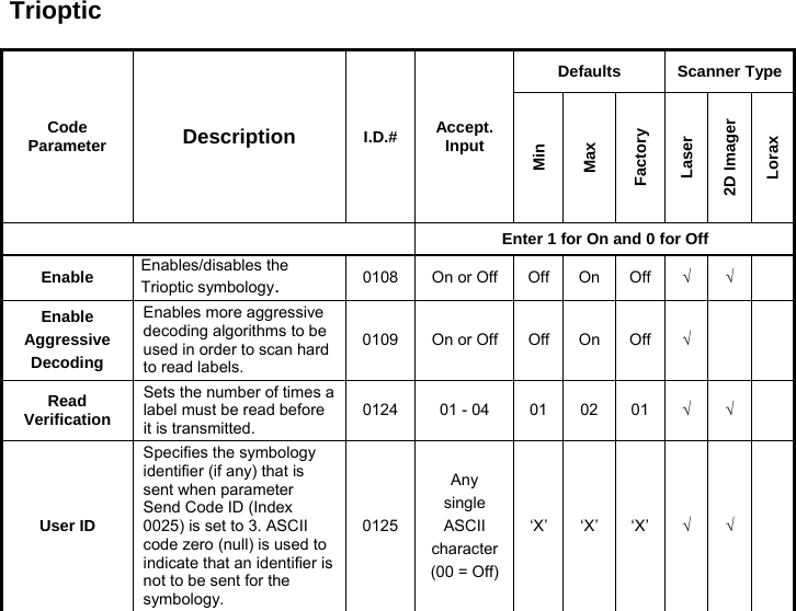
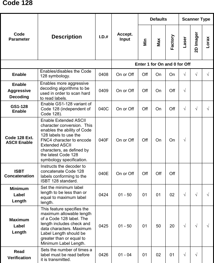
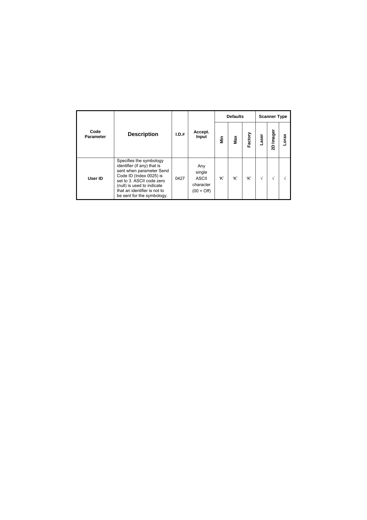
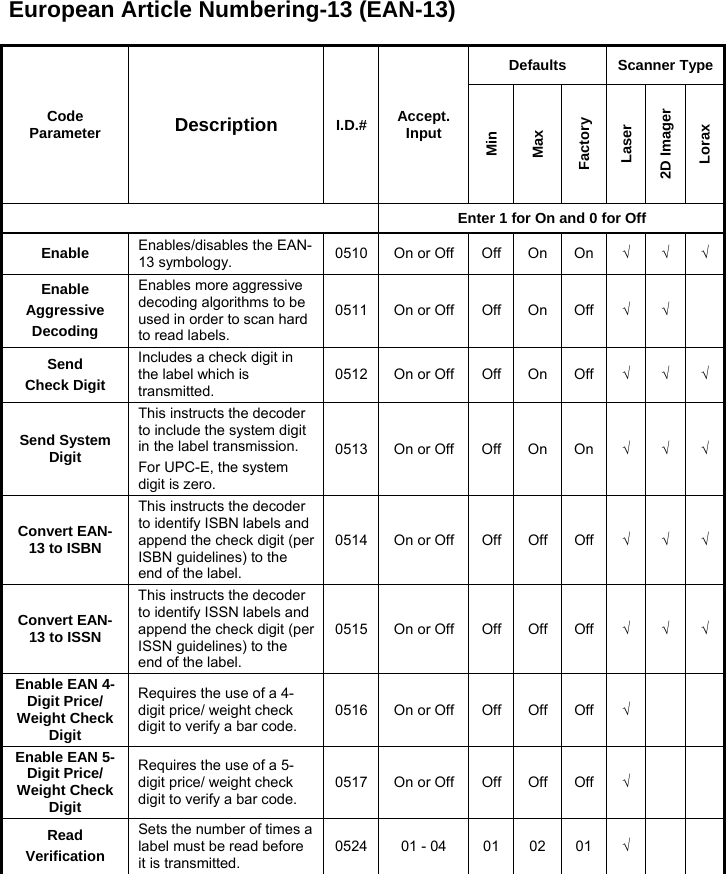

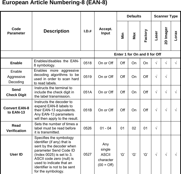
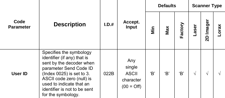
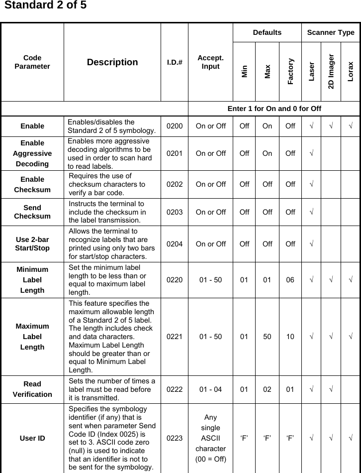
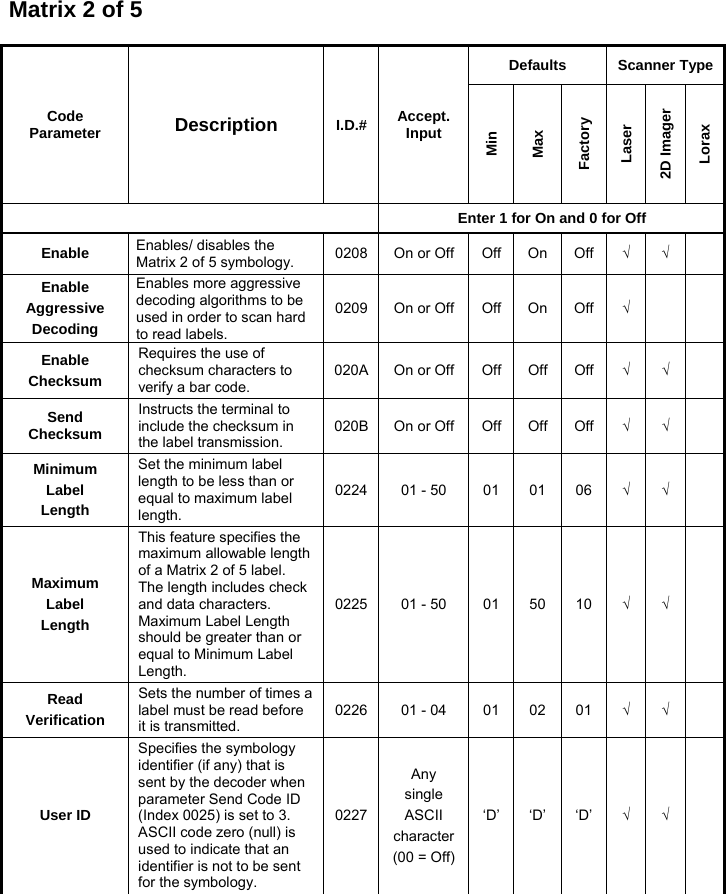
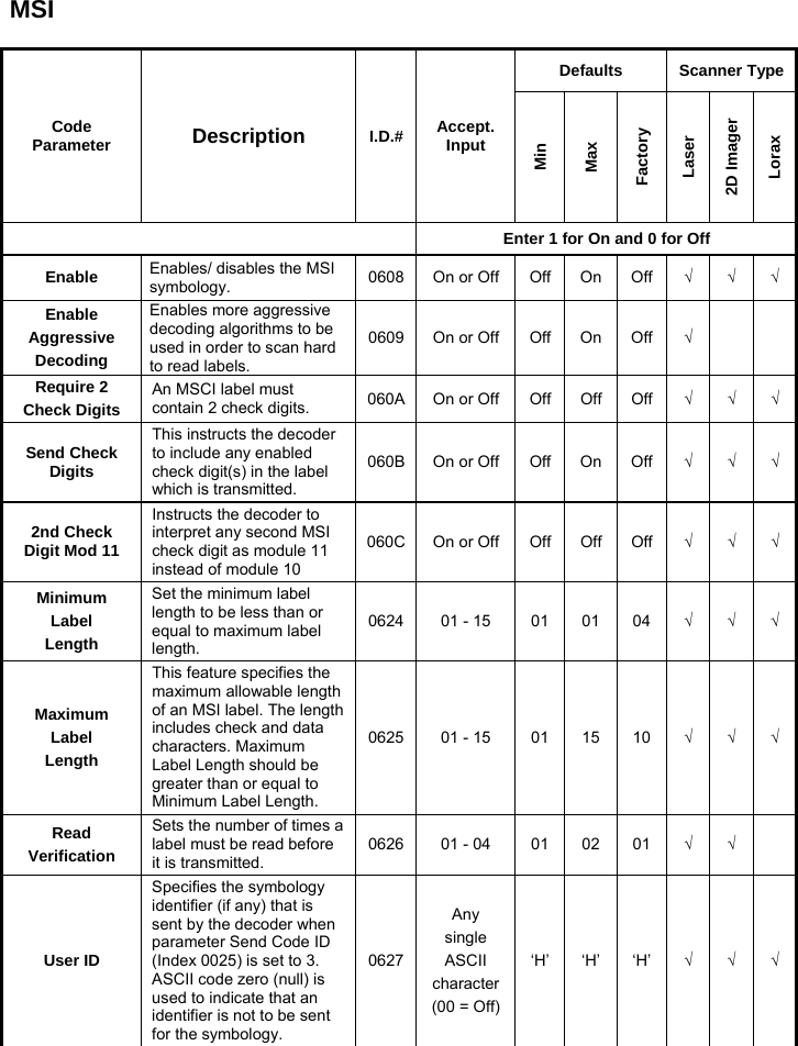
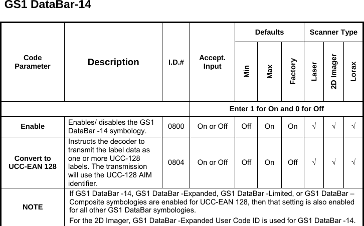
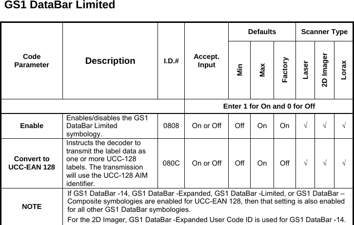
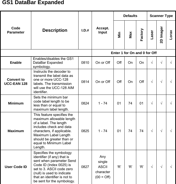
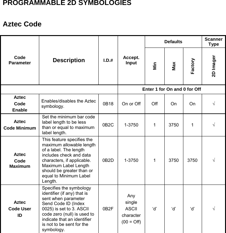
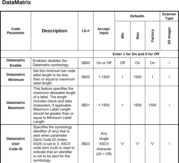
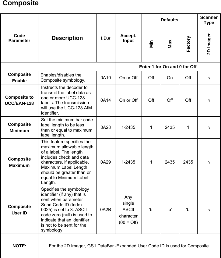

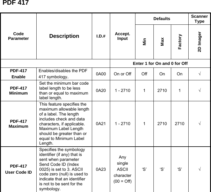
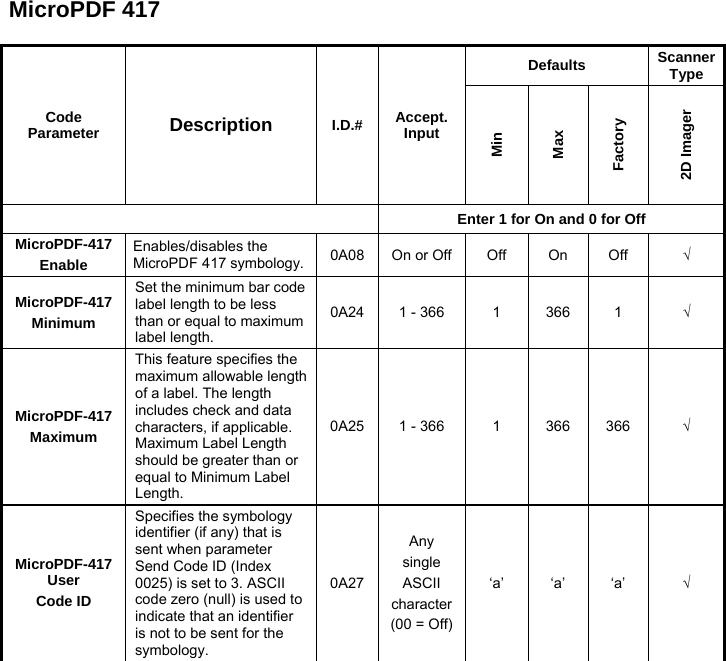
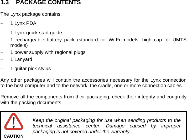
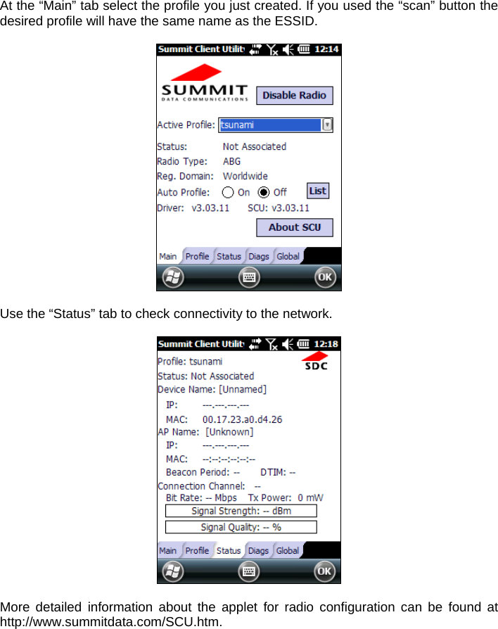
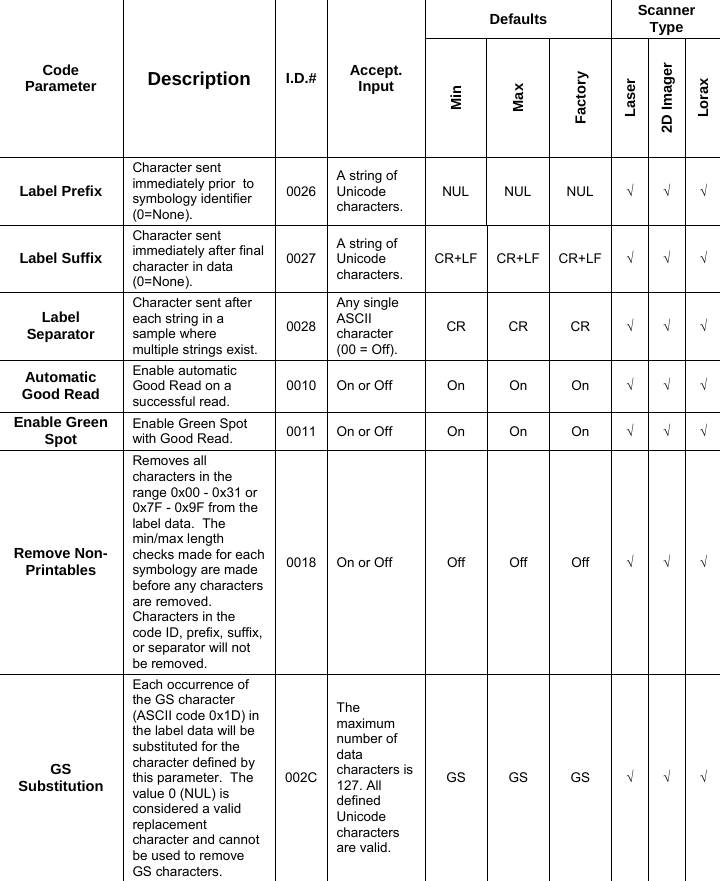
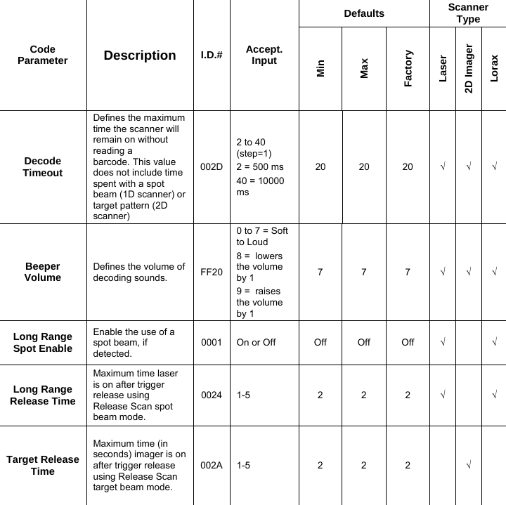
![OTHER CONTROLS Code Parameter Description I.D.# Accept. Input Defaults Scanner Type Min Max Factory Laser 2D Imager Lorax Enter 1 for On and 0 for Off Enable Label ProgrammingEnables/disables the ability to perform label programming. FF00 On or Off On On On √ √ √ Send Symbology Identifiers Specifies the symbology identifier (if any) that is sent by the decoder when parameter Send Code ID (Index 0025) is set to 3. ASCII code zero (null) used to indicate an identifier not to be sent for the symbology. 0025Select symbology identifier to transmit immediately preceding scanned data: 0=None 1=DLM identifier before label: <ID> " " <data> 2=AIM identifier before label: "]" <ID> <modifier> <data> 3=User defined identifier before label: <ID> <data> 4=DLM identifier after label: <data> " " <ID> 5=AIM identifier after label: <data> "]" <ID> <modifier> 6=User defined identifier after label: <data> <ID>00 01 00 √ √ √](https://usermanual.wiki/Datalogic-S-r-l/0073/User-Guide-1825795-Page-166.png)


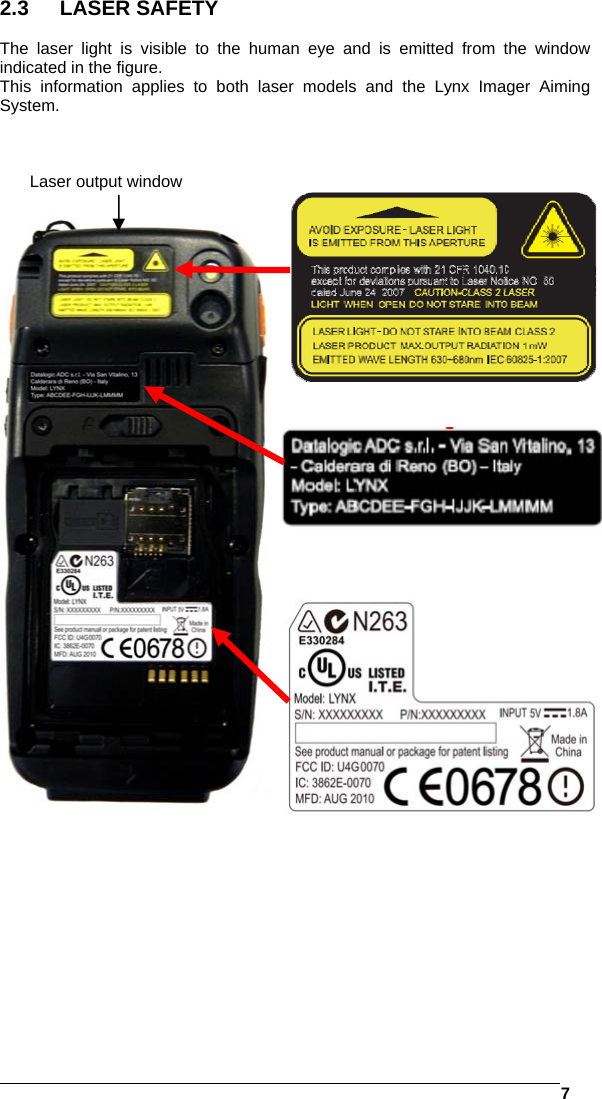
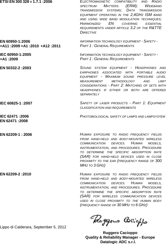
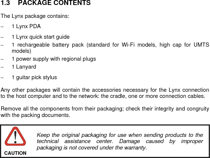
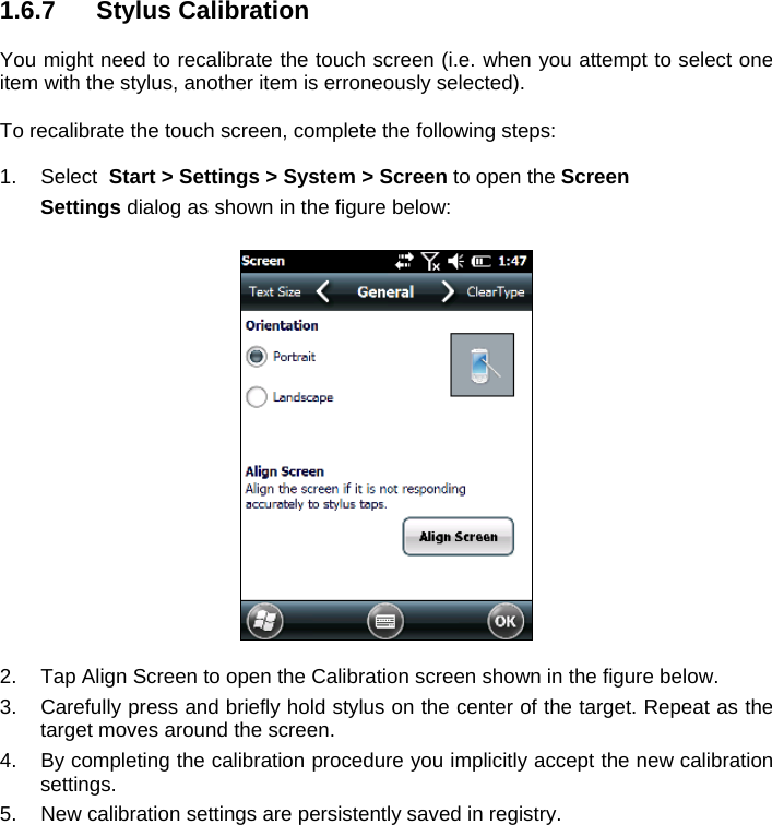
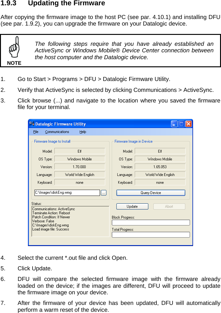
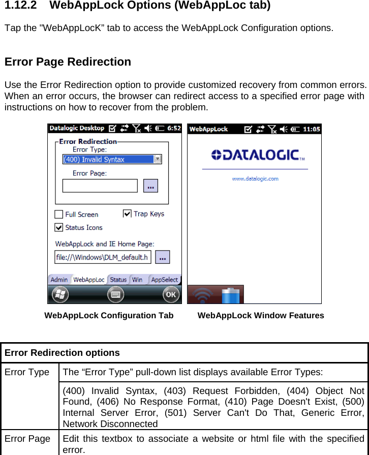
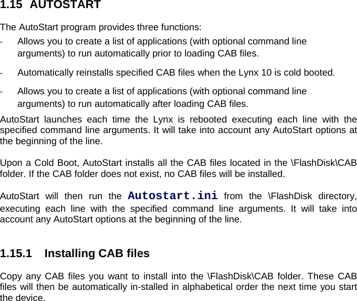
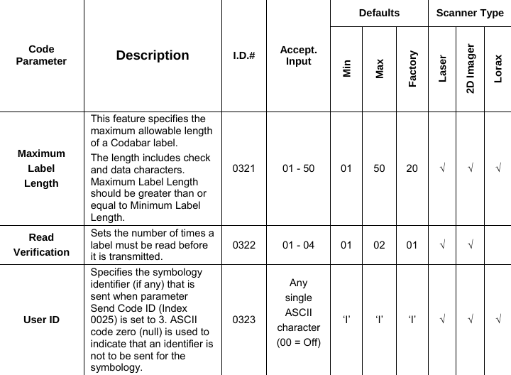
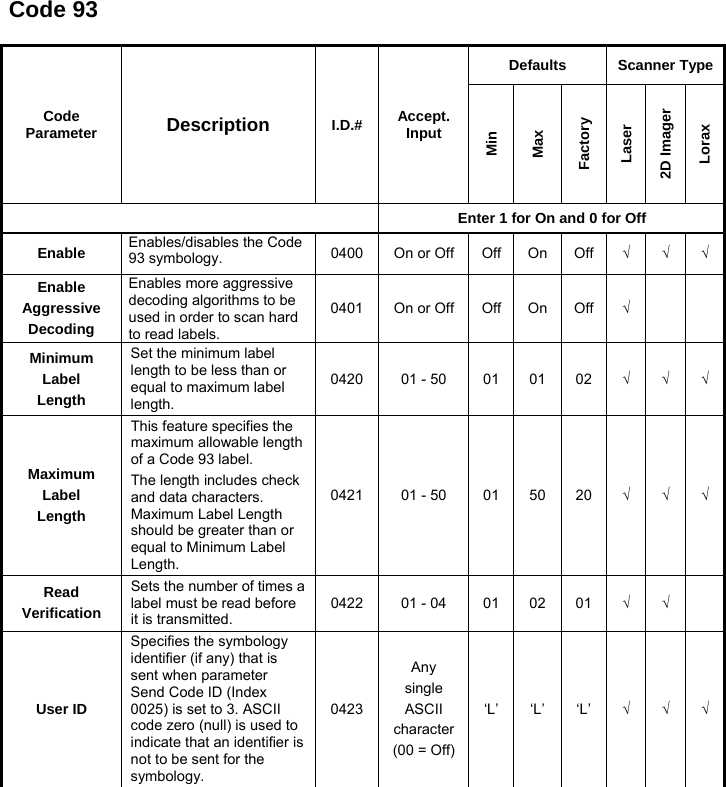
![18 2.9 SAR COMPLIANCE 1. For the used worst case positions, the portable device Lynx from Datalogic (FCC ID: U4G0070 and U4G0073) is in compliance with the IC RSS 102 Issue 4 [RSS 102] and Federal Communications Commission (FCC) Guidelines [OET 65] for uncontrolled exposure. SAR assessment in body worn was conducted with a distance of 15 mm between the housing of the handheld and the flat phantom. 2. EN 50360:2001: product standard to demonstrate the compliance of mobile phones with the basic restrictions related to human exposure to electromagnetic fields (300 MHz – 3 GHz). 3. EN 62209-1:2006 : Human exposure to radio frequency fields from hand-held and body-mounted wireless communication devices. Human models, instrumentation, and procedures. Procedure to determine the specific absorption rate (SAR) for hand-held devices used in close proximity to the ear (frequency range of 300 MHz to 3 GHz) 4. EN 62209-2 :2010: Human exposure to radio frequency fields from hand-held and body-mounted wireless communication devices. Human models, instrumentation, and procedures. Procedure to determine the specific absorption rate (SAR) for wireless communication devices used in close proximity to the human body (frequency range of 30 MHz to 6 GHz) 2.10 PATENTS This product is covered by one or more of the following patents: Design Pat.: EP 1711946; US D633502; CN ZL201030189483.7. Utility Patents: EP681257. Additional patents pending.](https://usermanual.wiki/Datalogic-S-r-l/0073/User-Guide-1825795-Page-206.png)