Datalogic S r l 0126 Joya Mobile Computer User Manual Joya R2U User s Manual
Datalogic ADC S.r.l. Joya Mobile Computer Joya R2U User s Manual
UserManual.wiki
>
Datalogic S r l
>
0126 User Manual
User Manual
Navigation menu
Upload a User Manual
Namespaces
Wiki Guide
HTML
PDF
Info
Views
User Manual
Discussion / Help
Navigation

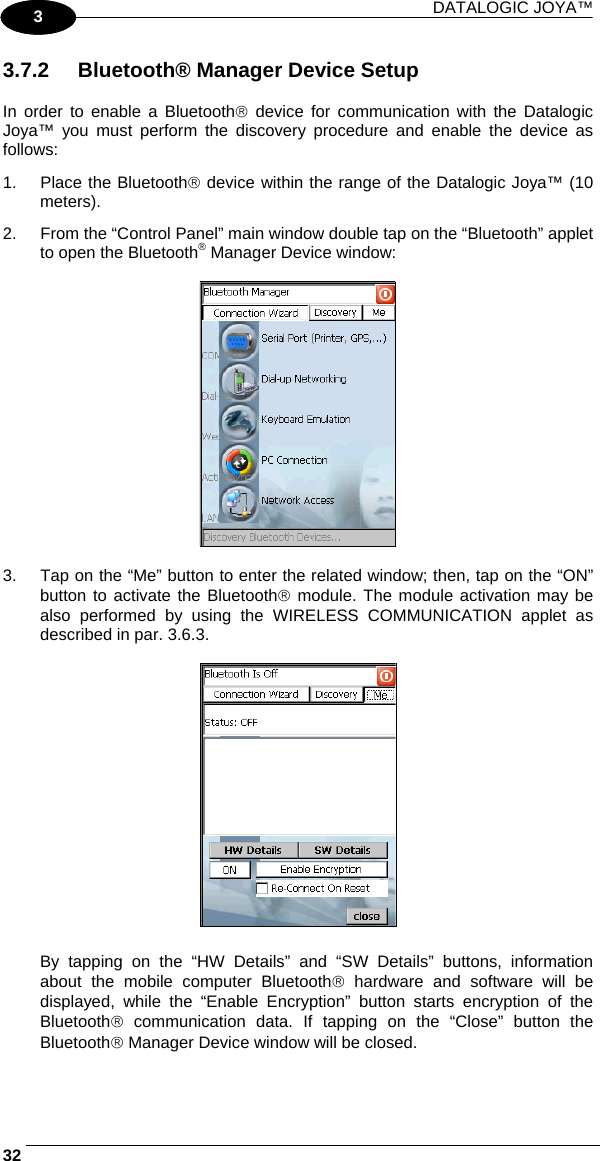
![USE AND FUNCTIONING 353 3.7.3 FTP Server Setup The Datalogic Joya™ Operating System includes a sample File Transfer Protocol (FTP) server. FTP is used for copying files to and from remote computer systems over a network using TCP/IP. You can establish a connection to your Datalogic Joya™ using its FTP Server through the following interfaces: WLAN using the WiFi radio Proceed as follows: 1. Create a registry file (extension .reg) to setup and enable FTP Server communication. A simple example file for anonymous logon is given below: REGEDIT4 [HKEY_LOCAL_MACHINE\Comm\FTPD] "DefaultDir"="\\" "AllowAnonymousUpload"=dword:00000001 "UseAuthentication"=dword:00000000 "BaseDir"="\\" "IsEnabled"=dword:00000001 "LogSize"=dword:00001000 "DebugOutputMask"=dword:00000017 "DebugOutputChannels"=dword:00000002 "IdleTimeout"=dword:0000012c "AllowAnonymous"=dword:00000001 "AllowAnonymousVroots"=dword:00000001 2. Copy this file to the Datalogic Joya™ using ActiveSync®. 3. Launch the .reg file from the Datalogic Joya™. 4. Perform a warm boot on the Datalogic Joya™. 5. From the PC > Explorer address bar (or running an FTP Client from the PC), enter the Datalogic Joya™ IP address. NOTE For more information on FTP Client/Server connections refer to the following web page: http://msdn2.microsoft.com/en-us/library/aa922316.aspx.](https://usermanual.wiki/Datalogic-S-r-l/0126/User-Guide-1285147-Page-57.png)
![DATALOGIC JOYA™ 361 3 3.8 BACKUP DIRECTORY FILE MANAGEMENT All of the Windows CE 5.0 system files reside in RAM (volatile memory) except for the Backup directory, which resides in FLASH (non-volatile memory). Therefore the contents of the Backup directory are persistent even if the mobile computer is re-booted or the battery pack is changed. You can save your more important files that you don't want to lose due to mobile computer re-boot, in the Backup directory or create a sub-directory within Backup. Even though the Windows Directory resides in RAM, it often contains files or sub-directories created by the user or by installation programs that you don't want to lose at re-boot. To keep these files persistent it is necessary to copy them to the directory \Backup\Windows. This directory doesn't exist originally (only Backup exists), and therefore it must be created. At the next cold boot, before activating the shell, Windows CE 5.0 will copy the contents including all sub-directories of \Backup\Windows to \Windows. Likewise, to maintain files that must be run at Windows CE 5.0 startup, (i.e. .exe, .lnk, .vb, .htm, etc.), it is necessary to copy them to the directory \Backup\Startup. This directory does not exist originally (only Backup exists), and therefore it must be created. The application programs will be run after any type of re-boot (both software and cold boot). As an alternative to the Safe Setup function, it is possible to copy the .cab files to the directory \Backup\Cabfiles (the Cabfiles sub-directory doesn't exists originally and must therefore be created) and perform a mobile computer cold boot to have the application installed. Once these files are copied to the directory \Backup\Cabfiles, the application will be run after each re-boot. From the second cold boot on, a message may be displayed such as "<application name> is already installed. Re-install?". This message blocks the boot process. Press the [Enter] key to continue the system initialization.](https://usermanual.wiki/Datalogic-S-r-l/0126/User-Guide-1285147-Page-58.png)