Datalogic S r l 0126 Joya Mobile Computer User Manual Joya R2U User s Manual
Datalogic ADC S.r.l. Joya Mobile Computer Joya R2U User s Manual
User Manual

Datalogic JoyaTM R2U
“Ready to Use”
User’s manual

Datalogic Mobile S.r.l.
Via S. Vitalino 13
40012 - Lippo di Calderara di Reno
Bologna - Italy
Datalogic Joya™ - User's Manual
Ed.: 12/2008
ALL RIGHTS RESERVED
The Datalogic name and logo are registered trademarks of Datalogic S.p.A. in many
countries.
The JOYA name and logo are a trademarks of Datalogic Mobile S.r.l.
All other brand and product names mentioned herein are for identification purposes only
and may be trademarks or registered trademarks of their respective owners.
Datalogic reserves the right to make modifications and improvements without prior
notification.
Datalogic shall not be liable for technical or editorial errors or omissions contained herein,
nor for incidental or consequential damages resulting from the use of this material.
© 2008 Datalogic Mobile S.r.l. • All rights reserved. • Protected to the fullest extent under
U.S. and international laws. • Copying, or altering of this document is prohibited without
express written consent from Datalogic Mobile S.r.l.

iii
CONTENTS
DATALOGIC END USER LICENSE AGREEMENT ...........................V
REFERENCES..................................................................................VII
Conventions .......................................................................................vii
Reference Documentation .................................................................vii
SAFETY REGULATIONS................................................................ VIII
General Safety Rules ........................................................................ viii
Bluetooth® Approval ......................................................................... viii
Laser Safety ........................................................................................ix
LED Class ......................................................................................... xiii
Radio Compliance.............................................................................xiv
FCC Compliance................................................................................xv
SAR Compliance................................................................................xv
Wireless and Radio Frequencies Warnings...................................... xvi
Patents ............................................................................................ xviii
WEEE Compliance.......................................................................... xviii
GENERAL VIEW...............................................................................XX
1 INTRODUCTION................................................................................. 1
1.1 Datalogic Joya™ Description.............................................................. 1
1.2 Model Description ............................................................................... 1
1.3 Package Contents............................................................................... 2
1.4 Accessories......................................................................................... 2
2 CONNECTIONS.................................................................................. 3
2.1 USB Connection.................................................................................. 3
2.2 WLAN Connection............................................................................... 4
2.3 WPAN Connections ............................................................................ 6
3 USE AND FUNCTIONING .................................................................. 7
3.1 Startup................................................................................................. 7
3.1.1 Using the Stylus (available only on Joya+TM) ...................................... 8
3.2 Data Capture....................................................................................... 9
3.2.1 Laser Data Capture............................................................................. 9
3.3 Description of the Keys ..................................................................... 10
3.3.1 Resetting the Joya™......................................................................... 11
3.4 Status Indicators ............................................................................... 12
3.4.1 Taskbar ............................................................................................. 12
3.5 Data Capture Configuration............................................................... 13
3.5.1 Configure........................................................................................... 13
3.5.2 Capture.............................................................................................. 17
3.6 Control Panel .................................................................................... 18
3.6.1 Registry ............................................................................................. 18
3.6.2 Files Admin ....................................................................................... 20
3.6.3 Wireless Communications................................................................. 22
3.6.4 Using Summit Radio Card Utility....................................................... 23
3.6.5 Stylus Calibration (available only on Joya+™).................................. 28

iv
3.7 Windows Connections....................................................................... 30
3.7.1 Microsoft® ActiveSync®.................................................................... 30
3.7.2 Bluetooth® Manager Device Setup................................................... 32
3.7.3 FTP Server Setup.............................................................................. 35
3.8 Backup Directory File Management .................................................. 36
3.9 Firmware Update............................................................................... 37
4 MAINTENANCE................................................................................ 40
4.1 Charging the Battery Pack ................................................................ 40
4.2 Replacing the Battery Pack............................................................... 41
4.3 Cleaning the Mobile Computer.......................................................... 44
5 JOYATM CRADLE DISPENSER........................................................ 45
5.1 Introduction ....................................................................................... 45
5.2 Accessories....................................................................................... 45
5.3 Installation requirements ................................................................... 46
5.3.1 Base Unit Construction Details ......................................................... 47
5.3.2 JoyaTM Cradle Dispenser Supports ................................................... 48
5.3.3 Internal Cabinet Space and Openings .............................................. 49
5.3.4 Anchoring and Maintenance Issues.................................................. 49
5.3.5 Power Supply Positioning and Cooling ............................................. 49
5.3.6 AC Power Cabling............................................................................. 50
5.3.7 Wiring ................................................................................................ 51
5.3.8 Cable to Power Supply Connection................................................... 52
5.3.9 Affixing Cables to Cabinet................................................................. 53
5.3.10 Safety Precautions ............................................................................ 53
5.3.11 Connection to AC Line Voltage......................................................... 54
5.4 JoyaTM cradle dispenser firmware ..................................................... 55
5.4.1 APC installation................................................................................. 55
5.4.2 Starting program................................................................................ 55
5.4.3 Reading firmware version.................................................................. 56
5.4.4 Firmware update procedure .............................................................. 57
5.5 JoyaTM – JoyaTM cradle dispenser connection................................... 57
5.6 Configuration..................................................................................... 58
5.7 Use and functioning .......................................................................... 58
6 JOYATM/JOYA+TM TECHNICAL FEATURES ................................. 59
6.1 Technical Data .................................................................................. 59
7 TEST CODES ................................................................................... 61
GLOSSARY ...................................................................................... 64
INDEX ............................................................................................... 66

v
DATALOGIC END USER LICENSE AGREEMENT
BY DOWNLOADING OR INSTALLING THE SOFTWARE, OR BY USING DATALOGIC
EQUIPMENT THAT INCLUDES THIS SOFTWARE, YOU ARE CONSENTING TO BE
BOUND BY THIS AGREEMENT. IF YOU DO NOT AGREE TO ALL OF THE TERMS OF
THIS AGREEMENT, THEN DO NOT DOWNLOAD, INSTALL, USE THE SOFTWARE
NOR DATALOGIC EQUIPMENT.
The following terms and conditions govern your use of the Software except to the extent that a particular
program (a) is the subject of a separate written agreement with Datalogic or (b) includes a separate “click-
on” license agreement as part of the installation and/or download process. Should a conflict arise between
the provisions of the foregoing documents, the order of precedence shall be (1) the written agreement, (2)
the click-on agreement, and (3) this agreement (“Agreement”).
1. License. Subject to the terms and conditions of and except as otherwise provided in this Agreement,
Datalogic Mobile S.r.l. (“Datalogic”) and its suppliers grant to Customer (“Customer”) a nonexclusive and
nontransferable license to use the specific program modules, feature set(s) or feature(s) in object code
form only as well as associated media, printed materials and “online” or electronic documentation (the
“Software”) for which Customer has paid, if required, the license fees. The Software is licensed not sold.
The license shall be subject to each of the following limitations:
• Unless otherwise expressly provided in the documentation, Customer shall use the Software solely
as embedded in, for execution on, or (where the applicable documentation permits installation on
non-Datalogic equipment) for communication with Datalogic equipment owned or leased by
Customer;
• Customer’s use of the Software shall be limited to use on a single hardware chassis, on a single
central processing unit, as applicable, or use on such greater number of chassis or central
processing units as Customer may have paid Datalogic the required license fee; and
• Customer’s use of the Software shall also be limited, as applicable and set forth in Customer’s
purchase order or in Datalogic’s product catalog, user documentation, or web site, to a maximum
number of (a) seats (i.e. users with access to the installed Software), (b) concurrent users,
sessions, ports, and/or issued and outstanding IP addresses, and/or (c) central processing unit
cycles or instructions per second. Customer’s use of the Software shall also be limited by any other
restrictions set forth in Customer’s purchase order or in Datalogic’s product catalog, user
documentation or web site for the Software.
2. General Limitations. Except as otherwise expressly provided under this Agreement, Customer shall
have no right, and Customer specifically agrees not to (i) transfer, assign or sublicense its license rights to
any other person, or use the Software on unauthorized or secondhand Datalogic equipment, and any such
attempted transfer, assignment or sublicense shall be void; (ii) correct errors to or otherwise modify or
adapt the Software or create derivative works based upon the Software, or to permit third parties to do the
same; or (iii) decompile, decrypt, reverse engineer, disassemble or otherwise reduce the Software to
human-readable form to gain access to trade secrets or confidential information in the Software. To the
extent required by law, at Customer's request, Datalogic shall provide Customer with the interface
information needed to achieve interoperability between the Software and another independently created
program, upon payment of Datalogic's applicable fee. Customer shall observe strict obligations of
confidentiality with respect to such information.
3. Upgrades and Additional Copies. For purposes of this Agreement, “Software” shall include (and the
terms and conditions of this Agreement shall apply to) any upgrades, updates, bug fixes or modified
versions (collectively, “Upgrades”) or backup copies of the Software licensed or provided to Customer by
Datalogic or an authorized distributor for which Customer has paid the applicable license fees.
Notwithstanding any other provision of this Agreement: (1) customer has no license or right to use any
such additional copies or upgrades unless customer, at the time of acquiring such copy or upgrade,
already holds a valid license to the original Software and has paid the applicable fee for the upgrade, if
required; (2) use of upgrades is limited to Datalogic equipment for which customer is the original end user,
purchaser or lessee or who otherwise holds a valid license to use the Software which is being upgraded;
and (3) use of additional copies is limited to backup purposes only.
4. Proprietary Notices. Customer agrees to maintain and reproduce all copyright and other proprietary
notices on all copies, in any form, of the Software in the same form and manner that such copyright and
other proprietary notices are included on the Software. Except as expressly authorized in this Agreement,
Customer shall not make any copies or duplicates or any Software without the prior written permission of
Datalogic. Customer may make such backup copies of the Software as may be necessary for Customer’s
lawful use, provided Customer affixes to such copies all copyright, confidentiality, and proprietary notices
that appear on the original.
5. Protection of Information. Customer agrees that aspects of the Software and associated
documentation, including the specific design and structure of individual programs, constitute trade secrets

vi
and/or copyrighted material of Datalogic. Customer shall not disclose, provide, or otherwise make
available such trade secrets or copyrighted material in any form to any third party without the prior written
consent of Datalogic. Customer shall implement reasonable security measures to protect such trade
secrets and copyrighted material. Software and documentation shall remain solely property of Datalogic.
6. Limited Warranty. If Customer obtained the Software directly from Datalogic, then Datalogic warrants that
during the Warranty Period (as defined below): (i) the media on which the Software is furnished will be free of
defects in materials and workmanship under normal use; and (ii) the Software will substantially conform to its
published specifications. The “Warranty Period” means a period beginning on the date of Customer’s receipt of
the Software and ending on the later of (a) ninety (90) days from the date of initial shipment of the Software by
Datalogic, or (b) the end of the minimum period required by the law of the applicable jurisdiction. The limited
warranties extend only to Customer as the original licensee. Customer's sole and exclusive remedy and the
entire liability of Datalogic and its suppliers under these limited warranties will be, at Datalogic’s sole option,
repair or replacement of the Software if reported (or, upon request, returned) to Datalogic. Except as expressly
granted in this Agreement, the Software is provided AS IS and with all faults. Datalogic does not warrant that
the Software is error free or that Customer will be able to operate the Software without problems or
interruptions. In addition, due to the continual development of new techniques for intruding upon and attacking
networks, Datalogic does not warrant that the Software or any equipment, system or network on which the
Software is used will be free of vulnerability to intrusion or attack. This warranty does not apply if the Software
(a) is licensed for beta, evaluation, testing or demonstration purposes for which Datalogic does not receive a
license fee, (b) has been altered, except by Datalogic, (c) has not been installed, operated, repaired, or
maintained in accordance with instructions supplied by Datalogic, (d) has been subjected to abnormal physical
or electrical stress, misuse, negligence, or accident, or (e) is used in ultra hazardous activities. If Customer
obtained the Software from a Datalogic reseller, the terms of any warranty shall be as provided by such
distributor, and Datalogic provides Customer no warranty with respect to such Software. The Software may
contain support for programs written in Java. Java technology is not fault tolerant and is not designed,
manufactured, or intended for use or resale as online control equipment in hazardous environments requiring
fail-safe performance, such as in the operation of nuclear facilities, aircraft navigation or communication
systems, air traffic control, direct life support machines, or weapons systems, in which the failure of Java
technology could lead directly to death, personal injury, or severe physical or environmental damage. Microsoft
Inc. has contractually obligated Datalogic to make this disclaimer.
7. Disclaimer of Warranties. Except as specified in this warranty, all expressed or implied conditions,
representations, and warranties including, without limitation, any implied warranty or condition of
merchantability, fitness for a particular purpose, non-infringement, satisfactory quality or arising from a course
of dealing, usage, or trade practice, are hereby excluded to the extent allowed by applicable law. To the extent
that an implied warranty cannot be excluded, such warranty is limited in duration to the warranty period.
8. Disclaimer of Liabilities. In no event will Datalogic or its suppliers be liable for any lost revenue, profit,
or data, or for special, indirect, consequential, incidental, or punitive damages however caused and arising
out of the use of or inability to use the Software even if Datalogic has been advised of the possibility of
such damages. In no event shall Datalogic or its suppliers' liability to customer, whether in contract, tort
(including negligence), or otherwise, exceed the price paid by customer. The foregoing limitations shall
apply even if the above-stated warranty fails of its essential purpose.
9. Term and Termination. This Agreement is effective until terminated. Customer may terminate this
Agreement at any time by destroying all copies of Software including any documentation. Customer’s
license rights under this Agreement will terminate immediately without notice from Datalogic if Customer
fails to comply with any provision of this Agreement. Upon termination, Customer must destroy all copies
of Software in its possession or control.
10. Customer Records. Customer grants to Datalogic and its independent accountants the right to
examine Customer’s books, records and accounts during Customer’s normal business hours to verify
compliance with this Agreement. In the event such audit discloses non-compliance with this Agreement,
Customer shall promptly pay to Datalogic the appropriate license fees.
11. General Provisions. This Agreement shall be governed by and construed in accordance with the laws
of Italy. All disputes arising out of or in connection with this Agreement will be subject to the exclusive
jurisdiction of the competent Court of the place where Datalogic has its registered office. If any portion
hereof is found to be void or unenforceable, the remaining provisions of this Agreement shall remain in full
force and effect. Except as expressly provided herein, this Agreement constitutes the entire agreement
between the parties with respect to the license of the Software and supercedes any conflicting or
additional terms contained in the purchase order.

vii
REFERENCES
CONVENTIONS
This manual uses the following conventions:
“User” refers to anyone using a Datalogic Joya™ mobile computer.
“Mobile computer” and "Datalogic Joya™" refer to Datalogic Joya™ mobile
computer.
“You” refers to the System Administrator or Technical Support person using this
manual to install, configure, operate, maintain or troubleshoot a Datalogic
Joya™ mobile computer.
“Cradle” refers to Datalogic Joya™ Cradle Dispenser.
REFERENCE DOCUMENTATION
For further information regarding Datalogic Joya™ refer to the SDK Help on-
Line.

viii
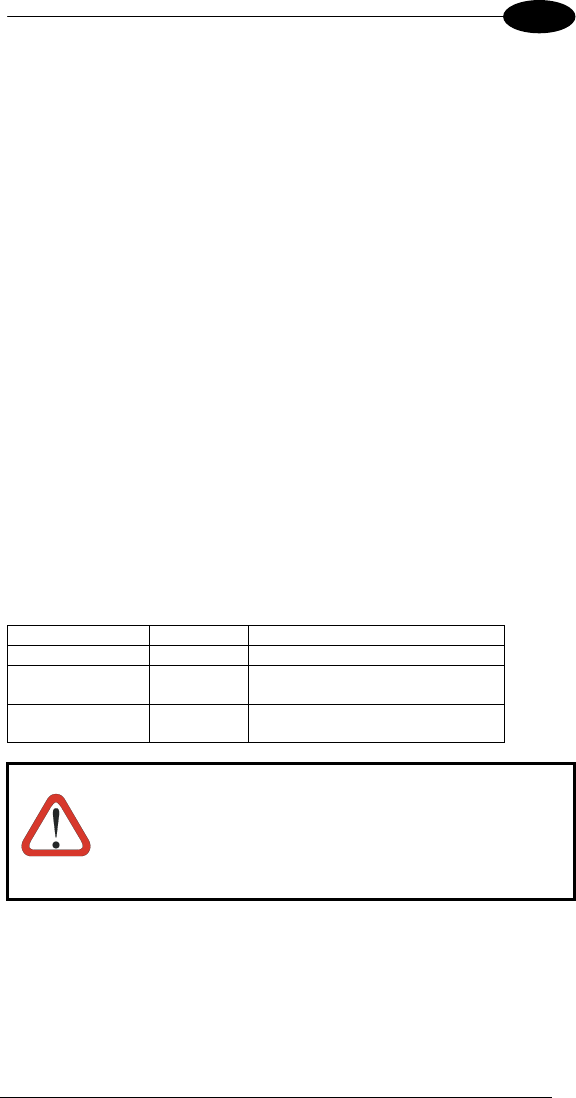
SAFETY REGULATIONS
NOTE
Read this manual carefully before performing any type of
connection to the Datalogic Joya™ mobile computer.
The user is responsible for any damages caused by incorrect
use of the equipment or by inobservance of the indication
supplied in this manual.
GENERAL SAFETY RULES
− Use only the components supplied by the manufacturer for the specific
Datalogic Joya™ being used.
− Do not attempt to disassemble the Datalogic Joya™ mobile computer, as it
does not contain parts that can be repaired by the user. Any tampering will
invalidate the warranty.
− When replacing the battery pack or at the end of the operative life of the
Datalogic Joya™ mobile computer, disposal must be performed in
compliance with the laws in force.
− Before using the device and the battery pack, see par. 4.2 and read every
warnings about the device and the battery pack.
− Do not submerge the Datalogic Joya™ in liquid products.
− The Datalogic Joya™ is designed and labelled to be compliant with laws,
rules and regulations in force in the countries where it is sold.
− For further information, refer to this manual and to the Datalogic Mobile
web site: www.mobile.datalogic.com.
BLUETOOTH® APPROVAL
This product is equipped with the following certified Bluetooth® module:
Product Name: Datalogic controller subsystem based on LBMALCS2 MURATA
module for Windows CE and Windows Mobile for portable barcode readers
application
Bluetooth ID: B016407
Product ID: DLBTLCS2
ix
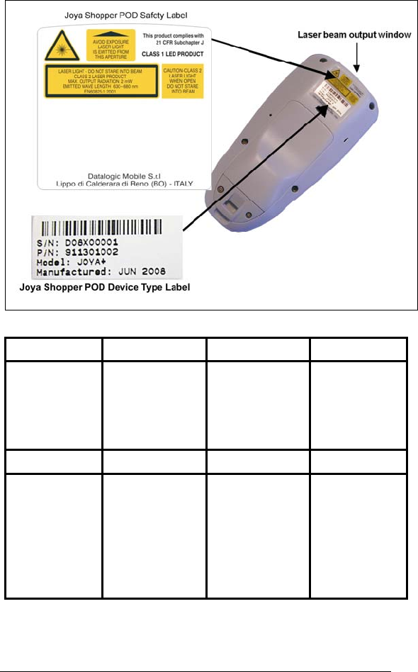
LASER SAFETY
The laser light is visible to the human eye and is emitted from the window
indicated in the figure.
I D F E
La luce laser è
visibile all'occhio
umano e viene
emessa dalla
finestra indicata
nella figura.
Die Laserstrahlung
ist für das
menschliche Auge
sichtbar und wird am
Strahlaustrittsfenster
ausgesendet (siehe
Bild).
Le rayon laser est
visible à l'oeil nu et il
est émis par la
fenêtre désignée sur
l'illustration dans la
figure.
La luz láser es
visible al ojo
humano y es
emitida por la
ventana indicada
en la figura.
I D F E
LUCE LASER
NON FISSARE IL
FASCIO
APPARECCHIO
LASER DI CLASSE 2
MASSIMA POTENZA
DI USCITA: 2mW
LUNGHEZZA D'ONDA
EMESSA: 650nm
CONFORME A EN
60825-1 (2001)
LASERSTRAHLUNG
NICHT IN DER STRAHL
BLINKEN
PRODUKT DER
LASERKLASSE 2
MAXIMALE
AUSGANGLEISTUNG:
2mW WELLENLÄNGE:
650nm
ENTSPR. EN 60825-1
(2001)
RAYON LASER
EVITER DE
REGARDER
LE RAYON
APPAREIL LASER DE
CLASSE 2
PUISSANCE DE
SORTIE: 2mW
LONGUER D'ONDE
EMISE: 650nm
CONFORME A EN
60825-1 (2001)
RAYO LÁSER
NO MIRAR FIJO EL
RAYO
APARATO LÁSER DE
CLASE 2
MÁXIMA POTENCIA
DE SALIDA: 2mW
LONGITUD DE ONDA
EMITIDA: 650nm
CONFORME A EN
60825-1
(2001)
x
ENGLISH
The following information is provided to comply with the rules imposed by
international authorities and refers to the correct use of your mobile computer.
STANDARD LASER SAFETY REGULATIONS
This product conforms to the applicable requirements of both CDRH 21 CFR
1040 Subchapter J and EN 60825-1:2001 at the date of manufacture.
For installation, use and maintenance, it is not necessary to open the device.
CAUTION
Do not attempt to open or otherwise service any
components in the optics cavity. Opening or servicing
any part of the optics cavity by unauthorized personnel
may violate laser safety regulations. The optics system is
a factory only repair item.
CAUTION
Use of controls or adjustments or performance of
procedures other than those specified herein may result
in exposure to hazardous visible laser light.
The product utilizes a low-power laser diode. Although staring directly at the
laser beam momentarily causes no known biological damage, avoid staring at
the beam as one would with any very strong light source, such as the sun.
Avoid that the laser beam hits the eye of an observer, even through reflective
surfaces such as mirrors, etc.
CAUTION
Use of optical systems with the scanner will increase eye
hazard. Optical instruments include binoculars,
microscopes, eye glasses and magnifying glasses.
ITALIANO
Le seguenti informazioni vengono fornite dietro direttive delle autorità
internazionali e si riferiscono all’uso corretto del terminale.
NORMATIVE STANDARD PER LA SICUREZZA LASER
Questo prodotto risulta conforme alle normative vigenti sulla sicurezza laser alla
data di produzione: CDRH 21 CFR 1040 sezione J e EN 60825-1:2001.
Non si rende mai necessario aprire l’apparecchio per motivi di installazione,
utilizzo o manutenzione.
CAUTION
Non tentare di accedere allo scomparto contenete i
componenti ottici o di farne la manutenzione.
L’apertura dello scomparto, o la manutenzione di qualsiasi
parte ottica da parte di personale non autorizzato, potrebbe
violare le norme della sicurezza. Il sistema ottico può essere
riparato solamente alla fabbrica.
xi
ATTENZIONE
L'utilizzo di procedure o regolazioni differenti da quelle
descritte nella documentazione può provocare
un'esposizione pericolosa a luce laser visibile.
Il prodotto utilizza un diodo laser a bassa potenza. Sebbene non siano noti
danni riportati dall’occhio umano in seguito ad una esposizione di breve durata,
evitare di fissare il raggio laser così come si eviterebbe qualsiasi altra sorgente
di luminosità intensa, ad esempio il sole. Evitare inoltre di dirigere il raggio laser
negli occhi di un osservatore, anche attraverso superfici riflettenti come gli
specchi.
CAUTION
L’uso di strumenti ottici assieme allo scanner può aumentare
il pericolo di danno agli occhi. Tali strumenti ottici includono
cannocchiali, microscopi, occhiali e lenti di ingrandimento.
DEUTSCH
Die folgenden Informationen stimmen mit den Sicherheitshinweisen überein, die
von internationalen Behörden auferlegt wurden, und sie beziehen sich auf den
korrekten Gebrauch vom Terminal.
NORM FÜR DIE LASERSICHERHEIT
Dies Produkt entspricht am Tag der Herstellung den gültigen EN 60825-1:2001
und CDRH 21 CFR 1040 Subchapter J Normen für die Lasersicherheit.
Es ist nicht notwendig, das Gerät wegen Betrieb oder Installations-, und
Wartungs-Arbeiten zu öffnen.
CAUTION
Unter keinen Umständen darf versucht werden, die
Komponenten im Optikhohlraum zu öffnen oder auf
irgendwelche andere Weise zu warten. Das Öffnen bzw.
Warten der Komponenten im Optikhohlraum durch
unbefugtes Personal verstößt gegen die Laser-
Sicherheitsbestimmungen. Das Optiksystem darf nur
werkseitig repariert werden.
ACHTUNG
Jegliche Änderungen am Gerät sowie Vorgehensweisen,
die nicht in dieser Betriebsanleitung beschrieben werden,
können ein gefährliches Laserlicht verursachen.
Der Produkt benutzt eine Laserdiode. Obwohl zur Zeit keine Augenschäden von
kurzen Einstrahlungen bekannt sind, sollten Sie es vermeiden für längere Zeit in
den Laserstrahl zu schauen, genauso wenig wie in starke Lichtquellen (z.B. die
xii
Sonne). Vermeiden Sie es, den Laserstrahl weder gegen die Augen eines
Beobachters, noch gegen reflektierende Oberflächen zu richten.
CAUTION
Die Verwendung von Optiksystemen mit diesem Scanner
erhöht die Gefahr einer Augenbeschädigung.
Zu optischen Instrumenten gehören unter anderem
Ferngläser, Mikroskope, Brillen und Vergrößerungsgläser.
FRANÇAIS
Les informations suivantes sont fournies selon les règles fixées par les autorités
internationales et se réfèrent à une correcte utilisation du terminal.
NORMES DE SECURITE LASER
Ce produit est conforme aux normes de sécurité laser en vigueur à sa date de
fabrication: CDRH 21 CFR 1040 sous-chapitre J et EN 60825-1:2001.
Il n’est pas nécessaire d’ouvrir l’appareil pour l’installation, l’utilisation ou
l’entretien.
CAUTION
Ne pas essayer d’ouvrir ou de réparer les composants de la
cavité optique. L’ouverture de la cavité optique ou la
réparation de ses composants par une personne non
qualifiée peut entraîner le nonrespect des règles de sécurité
relatives au laser. Le système optique ne peut être réparé
qu’en usine.
ATTENTION
L'utilisation de procédures ou réglages différents de ceux
donnés ici peut entraîner une dangereuse exposition à
lumière laser visible.
Le produit utilise une diode laser. Aucun dommage aux yeux humains n’a été
constaté à la suite d’une exposition au rayon laser. Eviter de regarder fixement
le rayon, comme toute autre source lumineuse intense telle que le soleil. Eviter
aussi de diriger le rayon vers les yeux d’un observateur, même à travers des
surfaces réfléchissantes (miroirs, par exemple).
CAUTION
L’utilisation d’instruments optiques avec le scanneur
augmente le danger pour les yeux. Les instruments
optiques comprennent les jumelles, les microscopes, les
lunettes et les verres grossissants.
xiii
ESPAÑOL
Las informaciones siguientes son presentadas en conformidad con las
disposiciones de las autoridades internacionales y se refieren al uso correcto
del terminal.
NORMATIVAS ESTÁNDAR PARA LA SEGURIDAD LÁSER
Este aparato resulta conforme a las normativas vigentes de seguridad láser a la
fecha de producción: CDRH 21 CFR 1040 Sección y EN 60825-1:2001.
No es necesario abrir el aparato para la instalación, la utilización o la
manutención.
CAUTION
No intente abrir o de ninguna manera dar servicio a ninguno
de los componentes del receptáculo óptico. Abrir o dar
servicio a las piezas del receptáculo óptico por parte del
personal no autorizado podría ser una violación a los
reglamentos de seguridad. El sistema óptico se puede
reparar en la fábrica solamente.
ATENCIÓN
La utilización de procedimientos o regulaciones diferentes
de aquellas describidas en la documentación puede causar
una exposición peligrosa a la luz láser visible.
El aparato utiliza un diodo láser a baja potencia. No son notorios daños a los
ojos humanos a consecuencia de una exposición de corta duración. Eviten de
mirar fijo el rayo láser así como evitarían cualquiera otra fuente de luminosidad
intensa, por ejemplo el sol. Además, eviten de dirigir el rayo láser hacia los ojos
de un observador, también a través de superficies reflectantes como los
espejos.
CAUTION
El uso de sistemas ópticos con el escáner aumentará el
riesgo de daños oculares. Los instrumentos ópticos incluyen
binoculares, microscopios, lentes y lupas.
LED CLASS
According to EN 60825-1:2001, the Datalogic Joya™ models which use the
good read spot LED are also CLASS 1 LED PRODUCTS.
APPARECCHIO LED CLASSE 1 PRODUIT LED DE CLASSE 1
PRODUKT LED KLASSE 1 PRODUCTO LED DE CLASE 1
xiv
RADIO COMPLIANCE
In radio systems configured with mobile computers and access points, the
frequencies to be used must be allowed by the spectrum authorities of the
specific country in which the installation takes place. Be absolutely sure that the
system frequencies are correctly set to be compliant with the spectrum
requirements of the country.
Information for the User
ENGLISH
Contact the competent authority responsible for the management of radio
frequency devices of your country to verify any possible restrictions or licenses
required.
Refer to the web site http://europa.eu.int/comm/enterprise/rtte/spectr.htm for
further information.
ITALIANO
Prendi contatto con l'autorità competente per la gestione degli apparati a radio
frequenza del tuo paese, per verificare eventuali restrizioni o licenze. Ulteriori
informazioni sono disponibili sul sito:
http://europa.eu.int/comm/enterprise/rtte/spectr.htm.
FRANÇAIS
Contactez l'autorité compétente en la gestion des appareils à radio fréquence
de votre pays pour vérifier d'éventuelles restrictions ou licences. Pour tout
renseignement vous pouvez vous adresser au site web:
http://europa.eu.int/comm/enterprise/rtte/spectr.htm.
DEUTSCH
Wenden Sie sich an die für Radiofrequenzgeräte zuständige Behörde Ihres
Landes, um zu prüfen ob es Einschränkungen gibt, oder eine Lizenz
erforderlich ist. Weitere Informationen finden Sie auf der Web Seite:
http://europa.eu.int/comm/enterprise/rtte/spectr.htm.
ESPAÑOL
Contacta la autoridad competente para la gestión de los dispositivos de radio
frecuencia de tu país, para verificar cualesquiera restricciones o licencias
posibles requerida. Además se puede encontrar mas información en el sitio
Web:
http://europa.eu.int/comm/enterprise/rtte/spectr.htm.

xv
FCC COMPLIANCE
Modifications or changes to this equipment without the expressed written
approval of Datalogic could void the authority to use the equipment.
This equipment has been tested and found to comply with the limits for a Class
B digital device, pursuant to Part 15 of the FCC Rules. These limits are
designed to provide reasonable protection against harmful interference in a
residential installation.
This equipment generates, uses and can radiate radio frequency energy and, if
not installed and used in accordance with the instructions, may cause harmful
interference to radio communications.
However, there is no guarantee that interference will not occur in a particular
installation.
If this equipment does cause harmful interference to radio or television
reception, which can be determined by turning the equipment off and on, the
user is encouraged to try to correct the interference by one or more of the
following measures:
− Reorient or relocate the receiving antenna.
− Increase the separation between the equipment and receiver.
− Connect the equipment into an outlet on a circuit different from that to
which the receiver is connected.
− Consult the dealer or an experienced radio/TV technician for help.
FCC ID: U4G0056 for JOYA+ (802.11b/g+BT) models.
FCC ID: U4G0126 for JOYA (802.11b/g only) models.
SAR COMPLIANCE
This product has been tested and found to comply with the following standards:
- OET BULLETIN 65 SUPPLEMENT C:2001: evaluating compliance with
FCC guidelines for human exposure to radio frequency electromagnetic
fields.
- EN 50392:2004: generic standard to demonstrate the compliance of
electronic and electrical apparatus with the basic restrictions related to
human exposure to electromagnetic fields (0 Hz- 300 GHZ).
xvi
WIRELESS AND RADIO FREQUENCIES WARNINGS
WARNING
Use only the supplied or an approved replacement antenna.
Unauthorized antennas, modifications or attachments could
damage the product and may violate laws and regulations.
WARNING
Most modern electronic equipment is shielded from RF signals.
However, certain electronic equipment may not be shielded
against the RF signals generated by Datalogic Joya™.
WARNING
Datalogic recommends persons with pacemakers or other
medical devices to follow the same recommendations provided
by Health Industry Manufacturers Associations for mobile
phones.
Persons with pacemakers:
• Should ALWAYS keep this device more than twenty five
(25) cm from their pacemaker and/or any other medical
device;
• Should not carry this device in a breast pocket;
• Should keep the device at the opposite side of the
pacemaker and/or any other medical device;
• Should turn this device OFF or move it immediately AWAY
if there is any reason to suspect that interference is taking
place.
• Should ALWAYS read pacemaker or any other medical
device guides or should consult the manufacturer of the
medical device to determine if it is adequately shielded
from external RF energy.
In case of doubt concerning the use of wireless devices with an
implanted medical device, contact your doctor.
WARNING
Turn this device OFF in health care facilities when any
regulations posted in these areas instruct you to do so.
Hospitals or health care facilities may use equipment that could
be sensitive to external RF energy.
WARNING
Do not use the device while driving: give full attention to driving
— driving safely is your first responsibility.
The device is not designed to be used with a GPS system. Any
program installed without Datalogic authorization may affect the
device's safety.
xvii
WARNING
RF signals may affect improperly installed or inadequately
shielded electronic systems in motor vehicles. Check with the
manufacturer or its representative regarding your vehicle. You
should also consult the manufacturer of any equipment that has
been added to your vehicle.
WARNING
An air bag inflates with great force. DO NOT place objects,
including either installed or portable wireless equipment, in the
area over the air bag or in the air bag deployment area. If
vehicle’s wireless equipment is improperly installed and the air
bag inflates, serious injury could result.
WARNING
Turn off the device when in any area with a potentially explosive
atmosphere. Observe restrictions and follow closely any laws,
regulations, warnings and best practices on the use of radio
equipment near fuel storage areas or distribution fuel areas,
chemical plants or where some operation involves use of
explosive materials.
Do not store or carry flammable liquids, explosive gases or
materials with the device or its parts or accessories.
Areas with a potentially explosive atmosphere are often, but not
always, clearly marked or showed.
Sparks in such areas could cause an explosion or fire, resulting
in injury or even death.

xviii
PATENTS
This product is covered by one or more of the following patents.
Design Pat.: EP 891,544.
U.S. Pat. 5,992,740; 6,808,114 B1; 6,997,385 B2; 7,387,246 B2
European Pat. 789,315 B1; 1,128,315 B1; 1,396,811 B1
Additional patents pending.
WEEE COMPLIANCE
Informazione degli utenti ai sensi della Direttiva Europea 2002/96/EC
L’apparecchiatura che riporta il simbolo del bidone barrato deve essere
smaltita, alla fine della sua vita utile, separatamente dai rifiuti urbani.
Smaltire l’apparecchiatura in conformità alla presente Direttiva consente di:
evitare possibili conseguenze negative per l’ambiente e per la salute
umana che potrebbero invece essere causati dall’errato smaltimento
dello stesso;
recuperare materiali di cui è composto al fine di ottenere un
importante risparmio di energia e di risorse.
Per maggiori dettagli sulle modalità di smaltimento, contattare il Fornitore dal
quale è stata acquistata l’apparecchiatura o consultare la sezione dedicata sul
sito www.mobile.datalogic.com.
Information for the user in accordance with the European Commission
Directive 2002/96/EC
At the end of its useful life, the product marked with the crossed out wheeled
wastebin must be disposed of separately from urban waste.
Disposing of the product according to this Directive:
avoids potentially negative consequences to the environment and
human health which otherwise could be caused by incorrect disposal
enables the recovery of materials to obtain a significant savings of
energy and resources.
For more detailed information about disposal, contact the supplier that provided
you with the product in question or consult the dedicated section at the website
www.mobile.datalogic.com.

xix
Information aux utilisateurs concernant la Directive Européenne
2002/96/EC
Au terme de sa vie utile, le produit qui porte le symbole d'un caisson à ordures
barré ne doit pas être éliminé avec les déchets urbains.
Éliminer ce produit selon cette Directive permet de:
éviter les retombées négatives pour l'environnement et la santé
dérivant d'une élimination incorrecte
récupérer les matériaux dans le but d'une économie importante en
termes d'énergie et de ressources
Pour obtenir des informations complémentaires concernant l'élimination,
veuillez contacter le fournisseur auprès duquel vous avez acheté le produit ou
consulter la section consacrée au site Web www.mobile.datalogic.com.
Información para el usuario de accuerdo con la Directiva Europea
2002/96/CE
Al final de su vida útil, el producto marcado con un simbolo de contenedor de
bassura móvil tachado no debe eliminarse junto a los desechos urbanos.
Eliminar este producto de accuerdo con la Directiva permite de:
evitar posibles consecuencias negativas para el medio ambiente y la
salud derivadas de una eliminación inadecuada
recuperar los materiales obteniendo así un ahorro importante de
energía y recursos
Para obtener una información más detallada sobre la eliminación, por favor,
póngase en contacto con el proveedor donde lo compró o consultar la sección
dedicada en el Web site www.mobile.datalogic.com.
Benutzerinformation bezüglich Richtlinie 2002/96/EC der europäischen
Kommission
Am Ende des Gerätelebenszyklus darf das Produkt nicht über den städtischen
Hausmüll entsorgt werden. Eine entsprechende Mülltrennung ist erforderlich.
Beseitigung des Produkts entsprechend der Richtlinie:
verhindert negative Auswirkungen für die Umwelt und die Gesundheit
der Menschen
ermöglicht die Wiederverwendung der Materialien und spart somit
Energie und Resourcen
Weitere Informationen zu dieser Richtlinie erhalten sie von ihrem Lieferanten
über den sie das Produkt erworben haben, oder besuchen sie unsere Hompage
unter www.mobile.datalogic.com.
xx
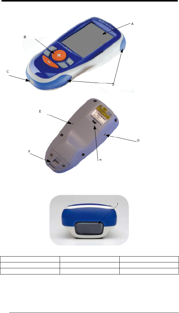
GENERAL VIEW
A) Display* D) Bumper G) Loudspeaker
B) 6 keys keyboard E) Cold reset Hole H) Micro USB
C) TTL Serial connector F) Neck Strip Anchor I) Laser window
*Remove protective film cover before use

xxi

INTRODUCTION
1
1
1 INTRODUCTION
1.1 DATALOGIC JOYA™ DESCRIPTION
The Datalogic Joya™ is a pocket-sized Windows powered mobile computer.
This extremely compact, lightweight, and versatile device, combines fully
integrated automatic data capture (1D bar code) and wireless communication
capabilities, supporting nearly any application.
The Datalogic Joya™ system architecture is based on the blend of Intel X-Scale
series processors coupled with the Windows CE operating system and it was
developed to meet the most demanding customer needs.
A huge quantity of on-board memory is available. it enables the user to adapt
the terminal for any specific need.
Thanks to its great ergonomics and the state of the art architecture, the
Datalogic Joya™ is the right answer to enhance your business opportunities.
1.2 MODEL DESCRIPTION
The brand new Datalogic Joya™ is available in two different models depending
on the options it is equipped with. All options are listed below:
• 911301003: JOYA R2U (base model)
• 911301004: JOYA+ R2U (enhanced model)
For further details about the Datalogic Joya™ models refer to the web site:
http://www.joya.datalogic.com.
DATALOGIC JOYA™
2
1 1
1.3 PACKAGE CONTENTS
The Datalogic Joya™ package contains:
− 1 Datalogic Joya™ mobile computer
Remove all the components from their packaging; check their integrity and
congruity with the packing documents.
CAUTION
Keep the original packaging for use when sending products
to the technical assistance center. Damage caused by
improper packaging is not covered under the warranty.
NOTE
Rechargeable battery packs are not initially charged.
Therefore the initial operation to perform is to charge them.
1.4 ACCESSORIES
Cradle
912201000 Datalogic Joya™ Cradle Dispenser
Batteries
91ACC1055 Datalogic Joya™ Battery Pack (10 pcs.)
Cradle Accessories
91ACC1000 Power Supply 12V 300W
91ACC0730 Power Junction Cable I90x/3 Cradle (8 pcs.)
91ACC0650 Term. Unlock Magnets (5 pcs.)
Various
94ACC1328 Datalogic Joya™ Stylus Pens (10 pcs)
91ACC1056 Datalogic Joya™ trolley holder (60 pcs.)
91ACC1057 Datalogic Joya™ checkout holder
NOTE
Use only a Datalogic Mobile-approved power supply and cables.
Use of an alternative power supply will invalidate any approval
given to this device and may be dangerous.
CONNECTIONS
3
2
2 CONNECTIONS
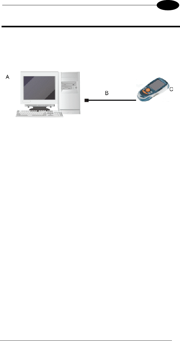
2.1 USB CONNECTION
You can use any standard micro USB cable to directly connect the Datalogic
Joya™ to a host computer to transfer data through the USB interface.
Key:
A) Host Computer C) Datalogic Joya™
B) Standard Micro USB cable type USB A – micro USB B
DATALOGIC JOYA™
4
1 2
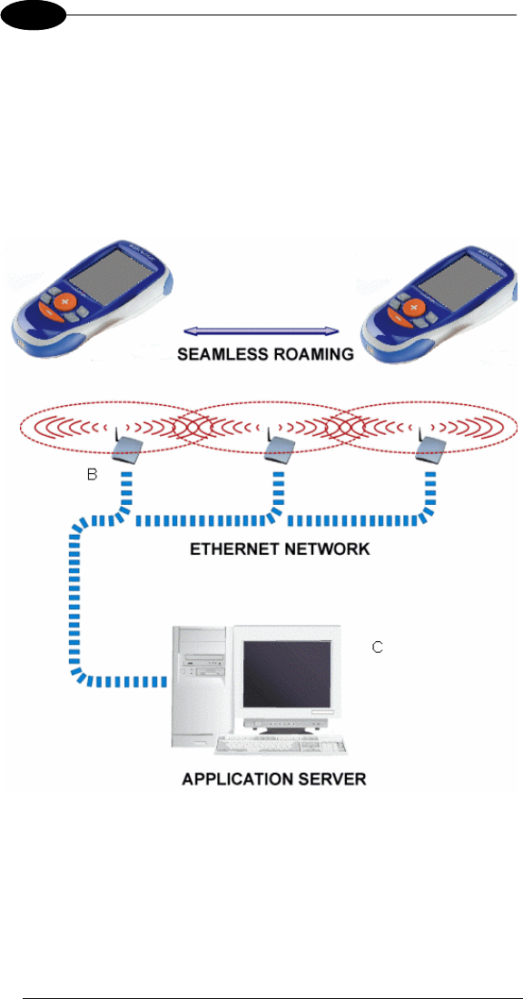
2.2 WLAN CONNECTION
Datalogic Joya™ Wi-Fi 802.11 b/g radio models can communicate with the host
using the on-board radio frequency component and an Access Point connected
to the host computer.
To launch this utility you can tap the specific icon if it's visible on the taskbar or
you can open Connections folder or Control Panel from desktop and select the
'Summit Client Utility' icon.
A
Key:
A) Datalogic Joya™
B) Access Point
C) Host – Application Server

CONNECTIONS
5
2
NOTE
Wi-Fi module is on by default, in order to avoid wasting
energy, you can switch it off using the Wireless
Communications applet.
NOTE
Suspending the terminal powers off the 802.11b/g radio and
drops the radio connection. When the terminal resumes,
depending on the radio power mode and security protocol
selected, it may take up to 30 seconds for the 802.11b/g radio
driver to re-associate the radio to the network.
NOTE
Area coverage and radio performance may vary, due to
environmental conditions, access points types or interference
caused by other devices (microwave ovens, radio
transmitters, etc.)
DATALOGIC JOYA™
6
1 2
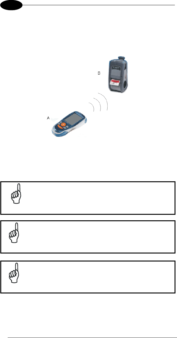
2.3 WPAN CONNECTIONS
Bluetooth® Datalogic Joya™ mobile computer models can communicate with a
Bluetooth® device, such as a printer, within a range of 10 m, using the on-board
Bluetooth® module.
Key:
A) Datalogic Joya™
B) Bluetooth® printer
NOTE
In order to avoid wasting energy, the Bluetooth® module is
off by default. If you need to have Bluetooth® working, the
module must be powered on using the Wireless
Communications applet (see par. 3.6.3), and perform the
Discovery procedure (see par. 3.7.2).
NOTE
Suspending the terminal powers off the Bluetooth
®
radio and
drops the piconet (Bluetooth
®
connection). When the terminal
resumes, it takes approximately 10 seconds for the
Bluetooth
®
radio driver to re-initialize the radio.
NOTE
Area coverage and Bluetooth
®
radio performance may vary,
due to environmental conditions or interference caused by
other devices (microwave ovens, radio transmitters, etc.), etc.
USE AND FUNCTIONING
7
3
3 USE AND FUNCTIONING
The use of the Datalogic Joya™ depends on the application software loaded.
However there are several parameters that can be set and utilities that can be
used to perform some basic functions such as data capture, communications,
file management, etc.
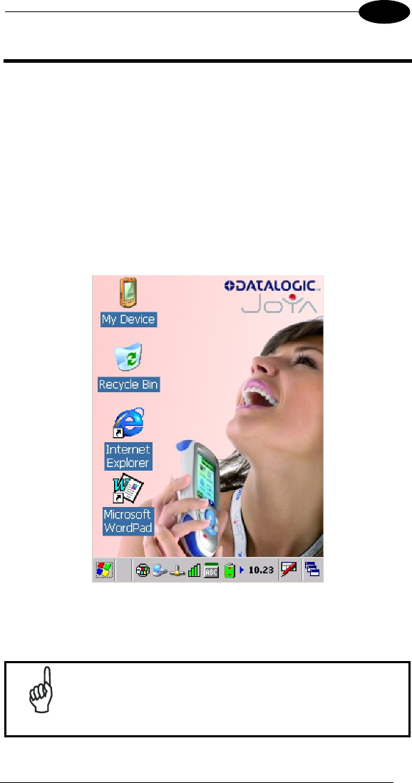
3.1 STARTUP
The Datalogic Joya™ turns on when a charged battery pack is inserted.
As soon as the mobile computer is on, the Windows CE 5.0 desktop
configuration will appear on the screen. Wait a few seconds before starting any
activity so that the mobile computer completes its startup procedure.
The mobile computer goes into power-off (low power with display and keyboard
backlight off), when it is no longer used for more than a programmable timeout,
which is defined in the POWER applet of the Control Panel. In this mode it can
be awakened (resuming operation) pressing the “Up” Key.
NOTE
The mobile computer can also be awakened or turned off by
the application program.

DATALOGIC JOYA™
8
1 3
3.1.1 Using the Stylus (available only on Joya+TM)
The stylus selects items and enters information. The stylus functions like a
mouse.
Double Tap: Touch the screen twice with the stylus to open items and
select options.
Drag: Hold the stylus on the screen and drag across the screen to
select text and images. Drag in a list to select multiple items.
Tap-and-hold: Tap and hold the stylus on an item to see a list of actions
available for that item. On the pop-up menu that appears, tap
the action you want to perform.
To recalibrate the touch screen use the Stylus Applet
CAUTION
Use only original Datalogic styluses supplied with the product
itself.
In harsh applications, use of screen protectors
should be taken into consideration, in order to extend the
touch screen operating life.
To prevent damage to the screen, do not use sharp devices or
any device other than the Datalogic Mobile-provided stylus.
Do not apply not necessary high pressures on the screen.
For applications where an intensive use of the touch screen is
foreseen, please consider that touch screen components are
subject to progressive wear.
USE AND FUNCTIONING
9
3
3.2 DATA CAPTURE
To capture data first of all select the barcode icon on the bottom-right side of the
display and tap the 'Capture' menu item then proceed with the following
directions.
To configure and enable data capture parameters refer to par. 3.5.
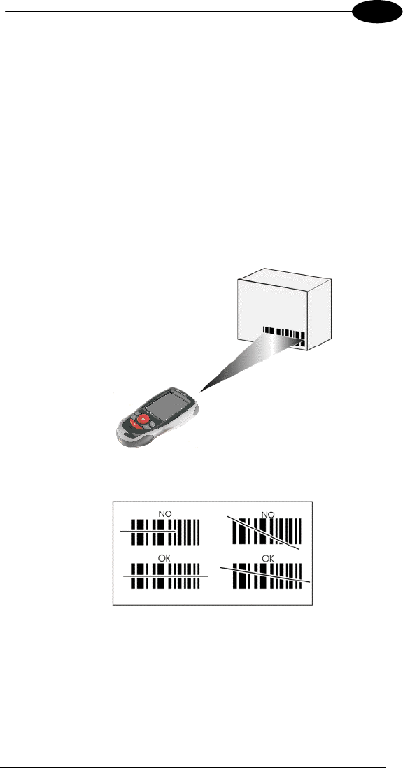
3.2.1 Laser Data Capture
To scan barcodes, point the Datalogic Joya™ laser model onto the code from a
distance within the reading range while pressing the “Up” key.
The lighted band emitted by the laser must completely intercept the barcode as
shown in the figure below. If enabled, the emission of an acoustic signal will
indicate that the scan has taken place correctly.
DATALOGIC JOYA™
10
1 3
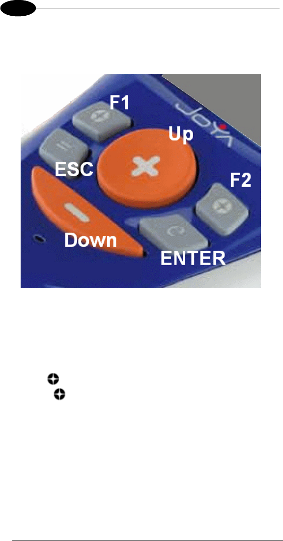
3.3 DESCRIPTION OF THE KEYS
The Datalogic Joya™ provides a 6-key keyboard. The following image shows
this keyboard.
Main Keys Function
Key “ + ”: it corresponds to ArrowUp Key.
Key “ - ”: it corresponds to ArrowDown Key.
Key “ Left ”: it corresponds to F1 (Function1) Key.
Key “ Right ”: it corresponds to F2 (Function2) Key.
Key “ = ”: it corresponds to ESC Key.
Key “ e ” : it corresponds to ENTER Key.
USE AND FUNCTIONING
11
3
3.3.1 Resetting the Joya™
There are two reset methods for the Joya™.
A warm boot terminates an unresponsive application and clears the working
RAM, but preserves both the file system and the registry.
A cold boot forces all applications to close and clears working RAM and files not
resident on the persistent flash memory. Registry is restored from persistent
memory if available or returned to factory default.
WARM BOOT
A warm boot closes all applications, clears the working RAM, but preserves the
file system and registry. If an application "hangs" initiate a warm boot to
terminate the application.
To perform a warm boot, press these keys simultaneously for 5 seconds:
“ + ” & “ - “
COLD BOOT
A cold boot is a complete reset of the Joya™ in which all applications are
forcibly closed and RAM is completely cleared. Registry is restored from
persistent memory if a saved copy is available (see 3.6.1) and RAM file system
completely erased. You will lose any applications and data (registry too) which
are not stored in persistent flash memory.
A cold boot is necessary when the Windows CE operating system locks up and
the warm boot command does not work.
To perform a cold boot, lightly press with a metallic clip inside the circle hole on
the back.
Warm Boot Cold Boot
REGISTRY Preserved Restored from flash (if available)
Flash Disk
(Backup Folder) Preserved Preserved
RAM File
System Preserved Reinitialized (factory default)
CAUTION
Before performing a reset, it is recommended to:
- execute a system backup to keep your more important
files and applications persistent. See par. 3.8;
- save the registry to non-volatile memory to guarantee
the persistence of the Windows configuration. See par.
3.6.1.
DATALOGIC JOYA™
12
1 3
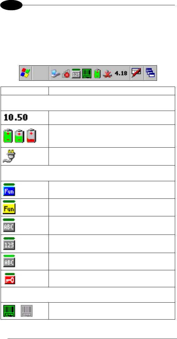
3.4 STATUS INDICATORS
3.4.1 Taskbar
The Taskbar provides information about the time, the battery level, the keyboard
function, and the decoding status.
ICONS DESCRIPTION
Time and Battery
Icons
It displays the time.
They are representative of five different icons indicating
the battery level. The icon is partially green when the
power left is >20% and partially red colored when the
power left is <20%.
It indicates that the battery is charging.
Keyboard Status
Icons
It indicates that the blue FUNC key has been pressed
and is going to affect the next key press.
It indicates that the yellow FUNC key has been pressed
and is going to affect the next key press.
It indicates that the ALPHA key has enabled the
selection of the characters printed in orange.
It indicates the NUMERIC key selection, the ALPHA key
has not been pressed.
It indicates that the ALPHA key has enabled the
selection of the characters printed in orange and the
Capslock is active.
It indicates that the keyboard is locked.
Decoding Status
Icons
It indicates that the decoder is active (green), not active
(grey).

USE AND FUNCTIONING
13
3
3.5 DATA CAPTURE CONFIGURATION
From the Taskbar, tap the "Decoding" icon to open a drop–down menu.
Decoding can also be accessed from the Control Panel.
By selecting the Info item from this drop-down menu you can access information
about the Scanner and the Software; the Configure item opens the configuration
applet (Data Capture Configuration Window), while Capture accesses the data
capture applet (Data Capture Window), which enables code reading.
The last menu item (Wedge) enables Wedge Emulation.
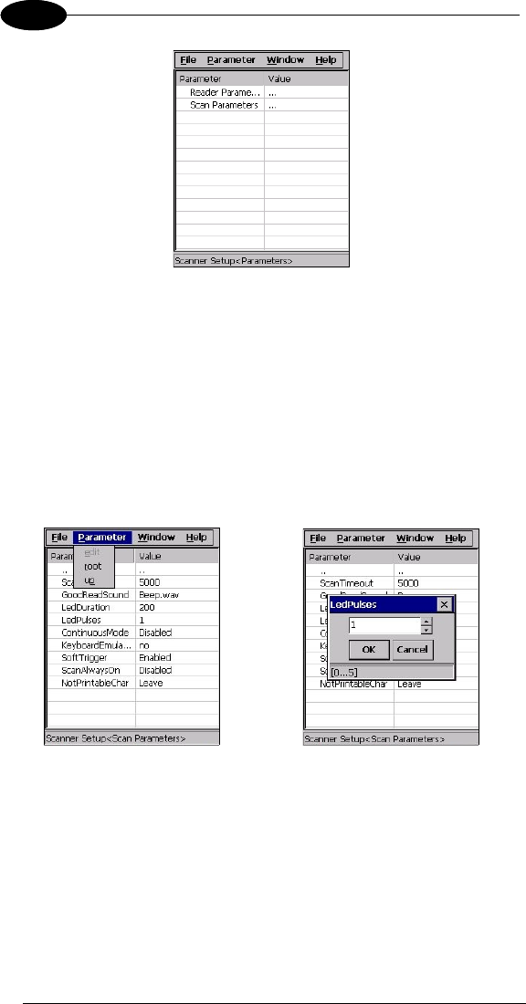
3.5.1 Configure
The Configuration applet contains the barcode scanning configuration
parameters in a directory tree structure. The available barcode parameters are
divided into two groups: Reader Parameters and Scan Parameters.
The Reader Parameters depend on the type of scanner module installed on the
mobile computer and allow barcode configuration (i.e. enable/disable Code 39,
check digit control, etc.).
The Scan Parameters are common to all scanner modules and allow control of
the scanning device (i.e. beeper control, LED control, laser timeout, etc.).
Each Data Capture screen window corresponds to a branch of the tree, and the
name of the current branch is displayed at the bottom of each screen window.
DATALOGIC JOYA™
14
1 3
Data Capture Configuration Window
The screen format shows two columns where the left column indicates branches
or parameters. Branches have three dots in the right column (...). You can
navigate through the tree structure using the stylus or keyboard arrows directly
on the item field or from the menu.
Parameters have their corresponding current values in the right column. You
can edit parameter values using the stylus or keyboard arrows directly on the
item field or from the menu. To change a value for example, select the line of
the value to be changed, choose Edit from the Parameter Menu then choose a
new value from the values listed in the box (see following figures).
Selecting Data Capture Setup Parameters
Alternatively using the stylus, you can tap once directly on the value on the right
column; continue tapping until the desired value is reached.
To activate a new configuration select the File ->Save Menu to send the new
configuration to the barcode decoding software and save the new configuration.
This will save the configuration to non-volatile memory preventing loss at the
next system reset.

USE AND FUNCTIONING
15
3
Reader Parameters
The barcode reading parameters and values are dependent upon the type of
scanner module mounted in your mobile computer. For a detailed list of
parameters and of their configuration procedures, please refer to the SDK Help
file on the CD.
Scan Parameters
The Scan Parameters are common to all scanner modules and allow control of
the scanning device. The Scan parameters are described as follows:
ScanTimeout: the maximum time, in milliseconds, during which the scanner
remains on without decoding any barcode.
BeepType: if set to dual tone, the good read beep is a sequence of high and
low pitch sounds. If set to monotone, the beep is a single pitch sound.
BeepDuration: the time interval, in milliseconds, during which the beeper will
sound when the scanner reads a code. To disable the beeper, set this value to 0.
BeepFrequency: determines the frequency in Hertz of the beeper.
GoodReadSound: is the beep sound emitted when the scanner reads a code.
LedDuration: the length of the good-read led pulse, in milliseconds.
LedPulses: the number of times the good-read led pulse is emitted when the
scanner reads a code.
ContinuousMode: disables the effect of the ScanTimeout parameter.
KeyboardEmulation: if enabled all scanned data are transformed into keyboard
events and can therefore be displayed and saved to a file as if input from the
mobile computer keyboard.
SoftTrigger: when enabled, the laser can be turned on/off by the application
software.
ScanAlwaysOn: enables the scanner for barcode reading independently from
the application software.
NotPrintableChar: if set to “Remove”, all not printable characters included in
the scanned data are deleted and the final barcode will include only printable
characters.
ScanButton: enables/disables the scan button. If the scan button is disabled,
the reader can be triggered under software control.
DATALOGIC JOYA™
16
1 3
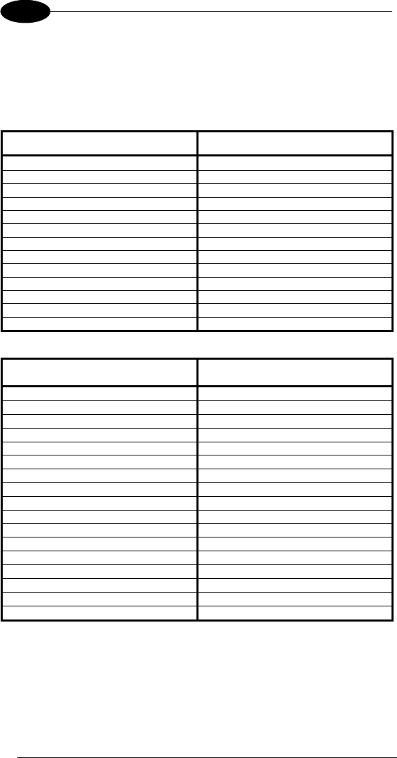
Default Settings
The following tables contain the default values for the major barcode setup
parameters, according to the type of scan engine mounted on the mobile
computer. For a complete list of parameters and of their configuration
procedures, please refer to the SDK Help file on the CD.
SCAN PARAMETERS LASER MODELS
ScanTimeout 5000
BeepType Dual tone
BeepDuration 20
BeepFrequency 2000
GoodReadSound Beep
LedDuration 200 ms
LedPulses 1
ContinuousMode Disabled
KeyboardEmulation Enabled
SoftTrigger Enabled
ScanAlwaysOn Disabled
NotPrintableChar Leave
ScanButton Enabled
BARCODE SYMBOLOGY
SPECIFIC READER PARAMETERS LASER MODELS
UPC A Enabled
UPC E Enabled
EAN 8 Enabled
EAN 13 Enabled
Code 39 Enabled
Code 39 Full ASCII Disabled
Code 32 Disabled
2/5: Interleaved Enabled
2/5: Industrial Disabled
2/5: Matrix Disabled
Code 128 Enabled
EAN 128 Enabled
Codabar Disabled
MSI Disabled
Plessey Disabled
Code 93 Disabled
Code 11 Disabled
USE AND FUNCTIONING
17
3
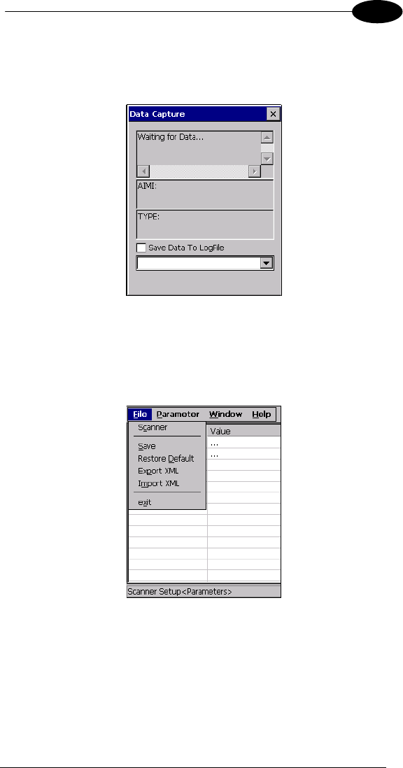
3.5.2 Capture
The Data Capture applet (Capture) enables code reading.
Data Capture Window
Data Capture can also be enabled through the Configuration applet by selecting
File ->Scanner from the main menu, or by enabling the parameter Scan Always
On in the Scan Parameters branch.
Enabling the Data Capture
DATALOGIC JOYA™
18
1 3
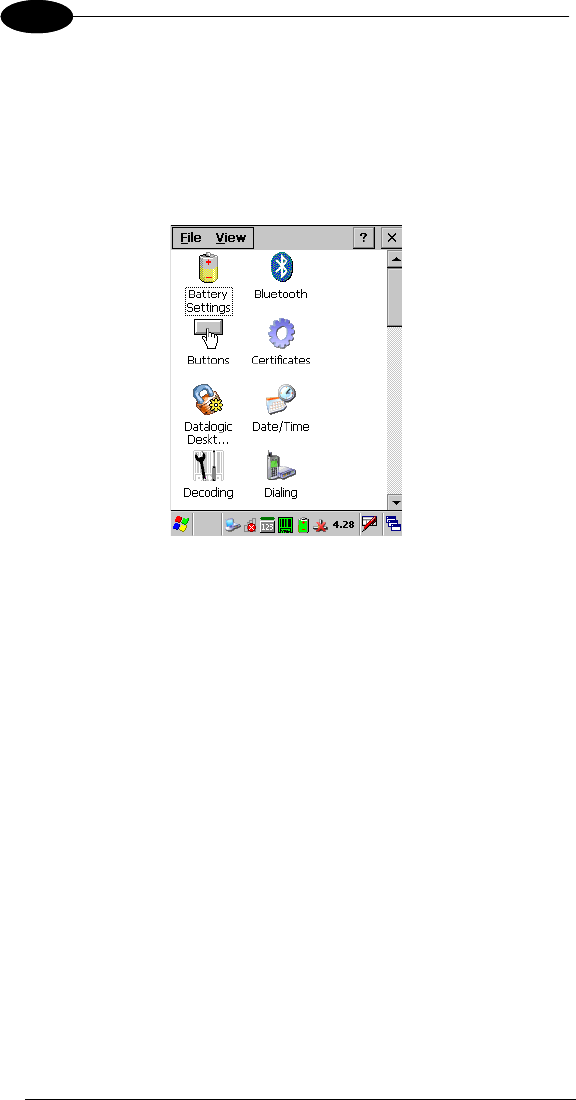
3.6 CONTROL PANEL
From the Desktop, double tap on the "My Device" icon and then double tap on
the "Control Panel" icon to open the control panel main window. The Control
Panel can also be launched from Start ->Settings ->Control Panel.
APPLET programs are displayed as icons; one icon corresponds to each
APPLET.
Control Panel
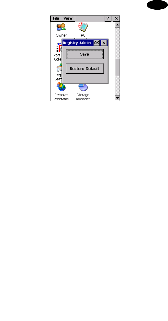
3.6.1 Registry
The REGISTRY ADMIN applet provides management of Windows CE 5.0
registry.
Select the REGISTRY ADMIN applet by double tapping the Registry Admin
icon.
The Registry Administration Main window appears. Two functions are available:
- Save Registry allows permanently saving the Windows configuration
(example: custom configuration of screen desktop background color, or
network adapter configuration) to non-volatile memory (SAVE button).
- Restore Default Registry allows restoring the initial factory default
configuration (Restore Default button). After restoring the factory default
configuration, you must perform a warm boot.
Saving the registry to non-volatile memory guarantees the persistence of the
Windows configuration in case of battery pack replacement and in case of a
Cold Boot.
USE AND FUNCTIONING
19
3
Registry Administration Window
DATALOGIC JOYA™
20
1 3
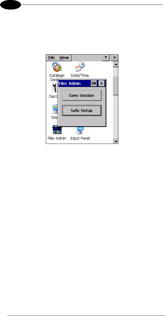
3.6.2 Files Admin
The FILES ADMIN applet enables control of the permanence of files in the
System Folder. Two functions are available on the Files Admin Main window by
means of two buttons:
Files Admin Main Window
Save Session: with this button all files will be permanently saved in the
\Windows directory in non-volatile memory. This function guarantees the steady
maintenance of every file produced during the current working session - even of
sub-directories and relevant files - with the exception of the files belonging to
the FLASH image.
These current working session files will be backed-up in the \Backup\Windows
directory.
At the next cold boot, the files previously saved in the \Backup\Windows
directory will be restored to the Windows directory (see par. 3.8).
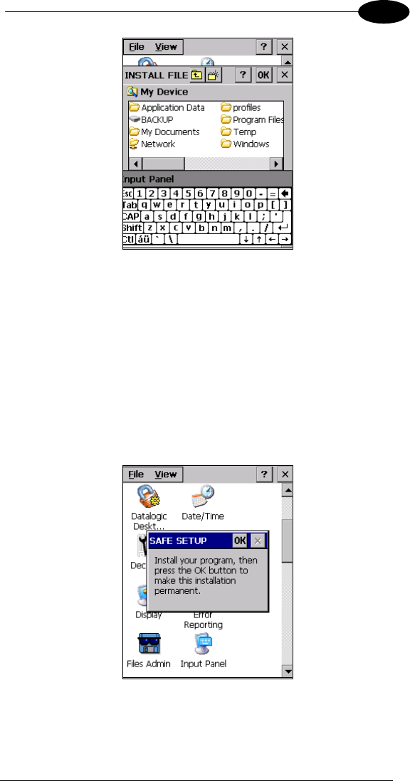
Safe Setup: with this button, the installation of software programs will be saved
to non-volatile memory (Backup directory). Before doing this, it will be checked
that the Backup directory has enough space to save the files. If the directory
space is not enough, an error message will be shown and the program will exit
the Safe Setup function.
Two activating procedures are available for Safe Setup:
- Select an installation file (for example, a .CAB cabinet file) from the Safe
Setup mask.
USE AND FUNCTIONING
21
3
Safe Setup First Mask
Then select \Windows or a relevant sub-directory in the path box. Then,
Safe Setup will recognize the new files and directories present in the
\Windows directory, and will copy them to the \Backup\Windows directory.
At the next cold boot, these files will be restored (see par. 3.8).
- Simply skip the first mask either by closing it or by pressing the ESC key.
When it closes, a new mask will pop up: it will enable any type of
installation (even remote ones like ActiveSync® installations). Make sure
the installation directory is \Windows or one of its sub-directories. After
installation, tap OK: Safe Setup will save the new files in the
\Backup\Windows directory.
Safe Setup Second Mask
DATALOGIC JOYA™
22
1 3
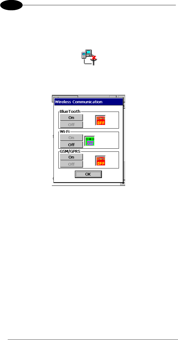
3.6.3 Wireless Communications
The WIRELESS COMMUNICATIONS applet provides management of the
802.11 b/g radio and of the Bluetooth® module.
Select the WIRELESS COMMUNICATIONS applet by double tapping the
Wireless Communications icon. The following window will appear:
Wireless Communications Window
USE AND FUNCTIONING
23
3
3.6.4 Using Summit Radio Card Utility
The Joya Summit WiFi card provides a useful client utility suitable for radio
configuration and site survey purposes.
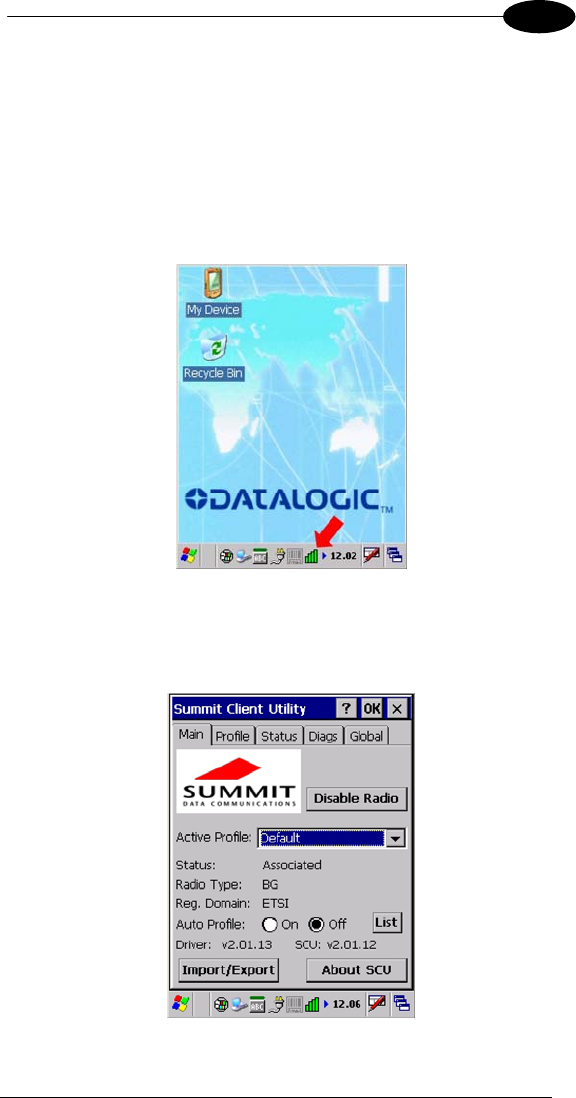
Summit Radio Card : Starting client
The client can be started from the Windows CE desktop by clicking the related
icon of the tool bar at the bottom.
Fig. 1 : Summit client utility
Summit Radio Card : Main screen
The following picture shows the screen when Summit Client is started
Fig. 2 : Client utility main
DATALOGIC JOYA™
24
1 3
The Active Profile window displays the current profile and lets user to change it.
The Disable Radio button turns off the radio card; after deactivation the same
button changes to Enable Radio so the radio can be reactivated.
To close the application, press the close button at upper-right corner of window.
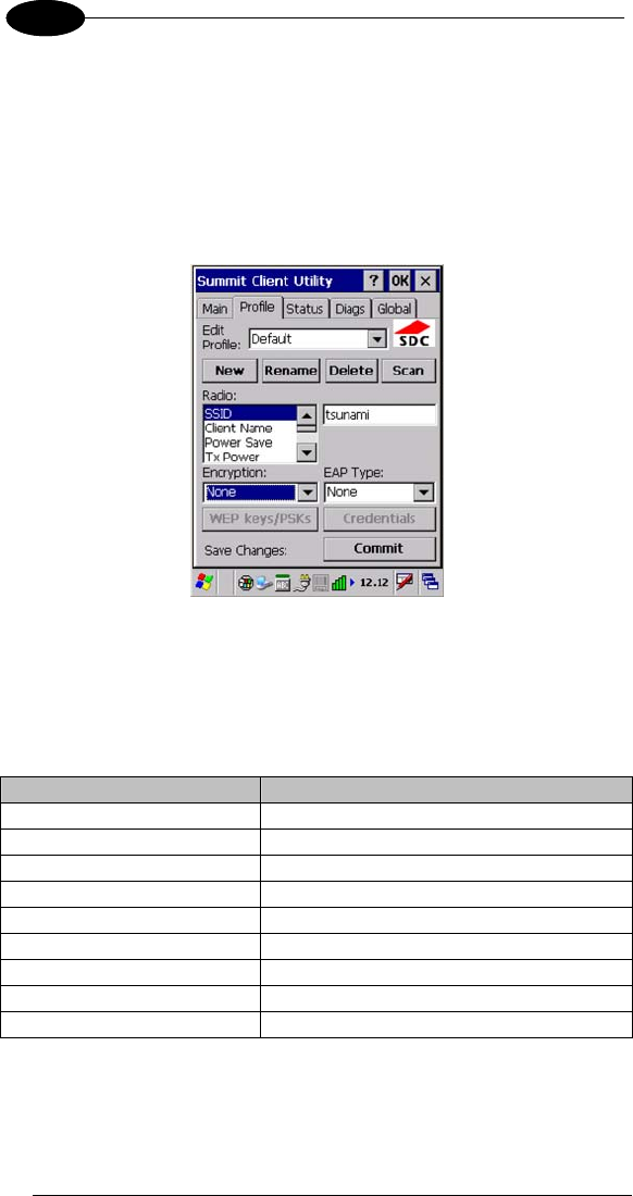
Summit Radio Card : Profile screen
Radio card is managed through radio profiles.
Fig. 3 : Profile manager
User can rename, delete, create and save any changes by the Rename, Delete,
New and Commit buttons.
The name chosen for the profile is his own identifier. Profile is defined by a set
of parameter that user can customize. The following is a simple profile for
testing.
Field Value
SSID tsunami
Client Name D08P00088 (the Joya S/N)
Power Save Fast
Tx Power Maximum
Bit Rate Auto
Radio Mode BG subset
Auth Type Open
EAP Type None
Encryption None
Once a new profile is created, remember to enable it from the Main windows.
USE AND FUNCTIONING
25
3
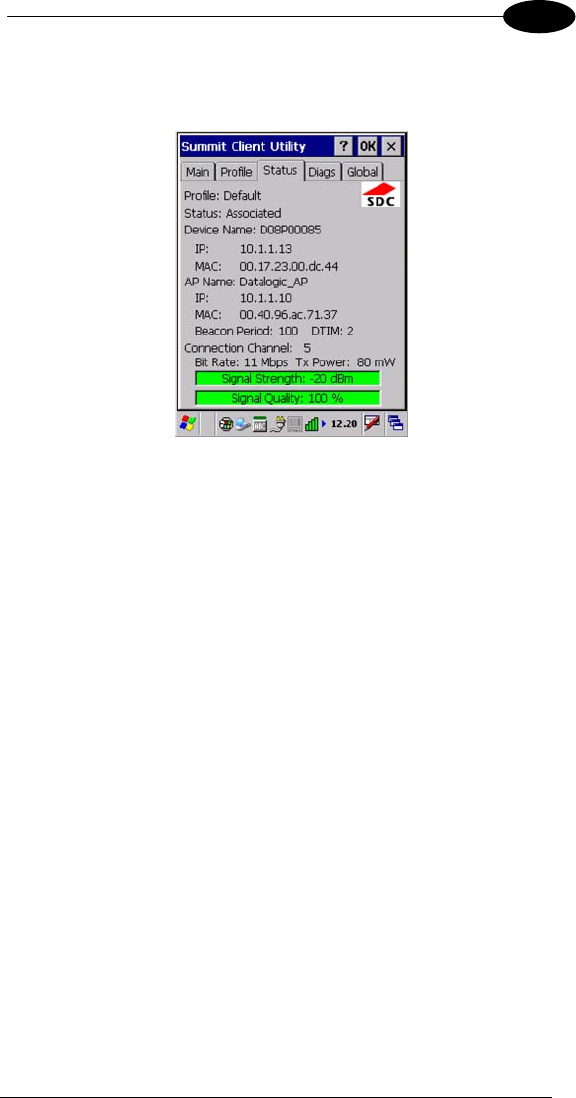
Summit Radio Card : Status screen
This screen shows the radio status related to the profile currently used.
Fig. 4 : Status screen
User can read current profile name, client device name, IP address and MAC
address. The Access Point to which the terminal is currently associated t is
specified by name, IP address and MAC address.
User can also read the signal strength (dBm), the transmission power (mW), the
WiFi channel, the rate (Mbps) and the signal quality.
DATALOGIC JOYA™
26
1 3
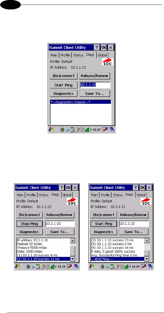
Summit Radio Card : Diagnostic screen
This screen allows user to interact with radio card to perform simple and useful
functionalities.
Fig. 5 : Diagnostic screen
The (Re)connect button disables and re-connects radio card.
The Release/Renew button releases and renews the radio interface IP address.
In order to test the radio link, user can ping the associated access point by
pressing the Start Ping button.
Fig. 6 : Start Ping
Fig. 7 : Stop Ping
The ping output is displayed on the large text windows
USE AND FUNCTIONING
27
3
The Diagnostic button displays the radio configuration and dumps available
profiles
Site Survey functionality is not available.
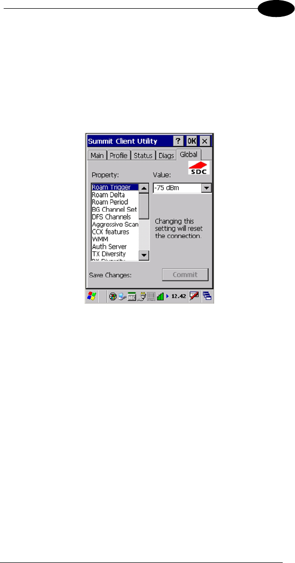
Summit Radio Card : Global Settings screen
There are many other parameters used to configure the radio card and they do
not depend on used profile, nevertheless for good working it’s recommended do
not change the default values.
Fig. 8 : Global screen
DATALOGIC JOYA™
28
1 3
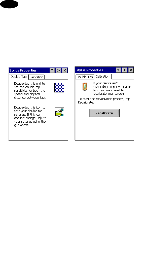
3.6.5 Stylus Calibration (available only on Joya+™)
You might need to recalibrate the touch screen (i.e. when you attempt to select
one item with the stylus, another item is erroneously selected).
To recalibrate the touch screen, complete the following steps:
1. Select Start > Settings > Control Panel > Stylus to open the Stylus
Properties dialog as shown in Figure 1.
2. Adjust Double-Tap sensitivity if needed or desired.
3. Select the Calibration tab to open the Calibration application.
Figure 1
4. Tap Recalibrate to open the Calibration screen shown in Figure 2.
5. Carefully press and briefly hold stylus on the center of the target. Repeat
as the target moves around the screen. Press the <ESC> key to cancel the
stylus calibration.
6. Press the <ENTER> key or tap the screen to accept the new calibration
settings. Press the <ESC> key to keep the old settings.
7. New calibration settings are persistently saved in registry.

USE AND FUNCTIONING
29
3
Figure 2
Startup stylus calibration
When starting the terminal, a stylus calibration screen comes up if valid
calibration settings are not available. This happens in the following
circumstances:
1. At the first startup of the terminal.
2. After restoring registry default settings using the applet Registry Admin
and performing a warm boot.
3. After a Clean Boot.
4. After a Firmware Update (see par. 3.9).

DATALOGIC JOYA™
30
1 3
3.7 WINDOWS CONNECTIONS
To connect the Datalogic Joya™ to another device (i.e. Host PC) from
Windows, several programs are available.
3.7.1 Microsoft® ActiveSync®
Microsoft® ActiveSync® gives you the possibility to connect your desktop
computer to your Datalogic Joya™ and synchronize the information on them.
Synchronization compares the data on the Datalogic Joya™ with that on the
desktop computer and updates both computers with the most recent
information.
With ActiveSync®, it is possible to:
- Back up and restore Datalogic Joya™ data.
- Copy files between Datalogic Joya™ and desktop computer.
- Synchronize files by selecting a synchronization mode.
You can establish an ActiveSync® connection to your Datalogic Joya™ through
the following electrical interfaces:
- USB directly
- Bluetooth® (see par. 3.7.2)
It is possible to constantly synchronize while connected to a desktop computer
or, alternatively, synchronization can be performed only when the synchronize
command is chosen. You can select which information types are synchronized
and control how much data is synchronized.
NOTE
By default, ActiveSync® does not automatically synchronize
all types of information. Use ActiveSync® options to turn
synchronization on and off for specific information types.
For example:
Synchronize Microsoft Word and Microsoft Excel files between the Datalogic
Joya™ and the desktop computer. The files will automatically be converted to
the correct format.
NOTE
Visit the following Microsoft Web site for the latest in updates
and technical information:
http://www.microsoft.com/windowsmobile/activesync/default.mspx

USE AND FUNCTIONING
31
3
ActiveSync® Remote
NOTE
Microsoft® ActiveSync® Remote is no longer supported in
Windows CE. For backward compatibility you can download
it from the Internet. We suggest enabling the FTP Server
and connecting to an FTP Client. See par. 3.7.3.
DATALOGIC JOYA™
32
1 3
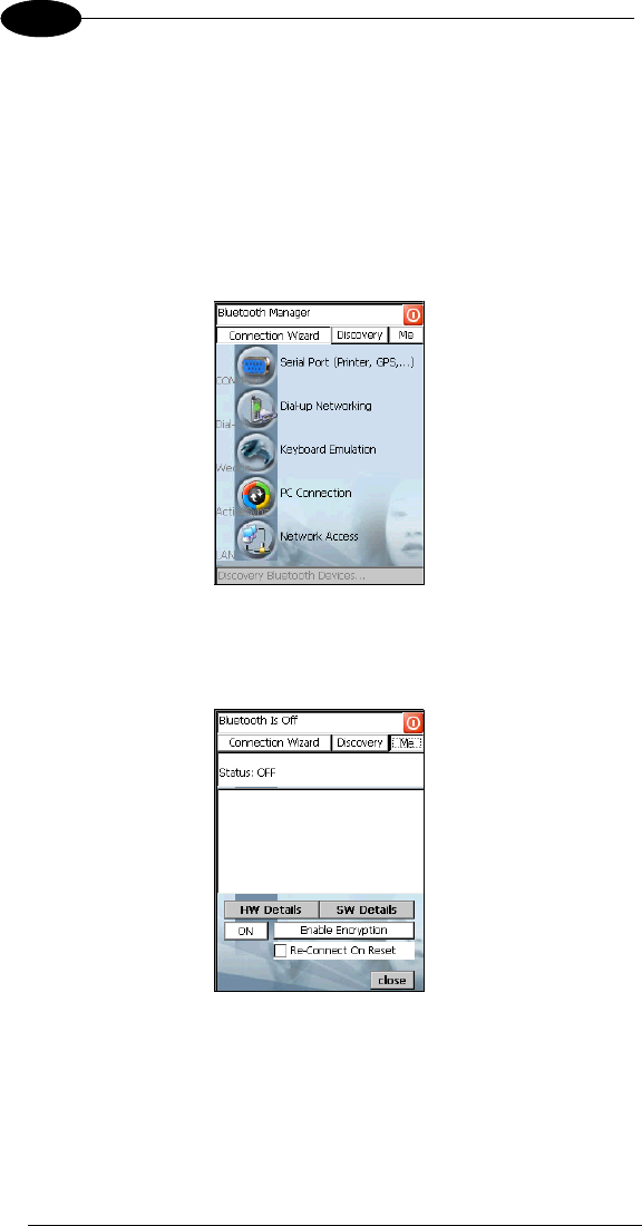
3.7.2 Bluetooth® Manager Device Setup
In order to enable a Bluetooth® device for communication with the Datalogic
Joya™ you must perform the discovery procedure and enable the device as
follows:
1. Place the Bluetooth® device within the range of the Datalogic Joya™ (10
meters).
2. From the “Control Panel” main window double tap on the “Bluetooth” applet
to open the Bluetooth® Manager Device window:
3. Tap on the “Me” button to enter the related window; then, tap on the “ON”
button to activate the Bluetooth® module. The module activation may be
also performed by using the WIRELESS COMMUNICATION applet as
described in par. 3.6.3.
By tapping on the “HW Details” and “SW Details” buttons, information
about the mobile computer Bluetooth® hardware and software will be
displayed, while the “Enable Encryption” button starts encryption of the
Bluetooth® communication data. If tapping on the “Close” button the
Bluetooth® Manager Device window will be closed.
USE AND FUNCTIONING
33
3
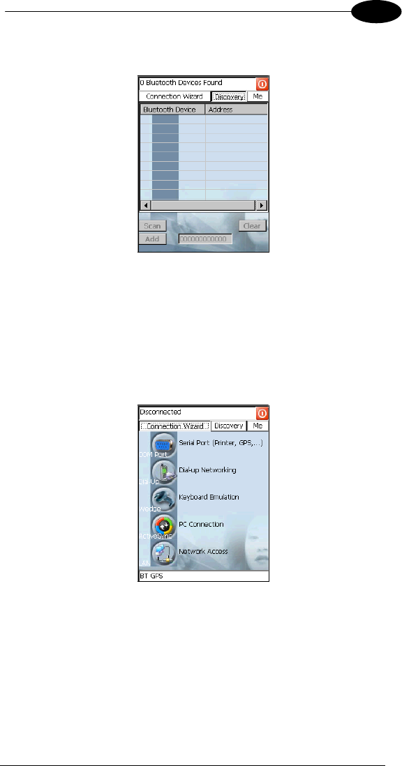
4. Tap on the “Discovery” button to enter the related window; then, tap on the
“Scan” button to run the Discovery procedure:
Once the Discovery procedure has been completed, select the desired
Bluetooth® device from the list. It is also possible to digit (12 hexadecimal
digits) the Bluetooth® address of the desired device by tapping on the
“Add” button. The “Clear” button deletes all discovered devices from the
list.
5. Once the desired Bluetooth® device has been selected, tap on the
“Connection Wizard” button to enter the related window where selecting
the connection type to be used for communication with the Bluetooth®
device:
The “Serial Port” button starts communication through the Bluetooth®
serial port COM 5 (typically used for connection with GPS devices).
The “Printer” button starts communication with a printer through the
Bluetooth® serial port COM 5.
The “Kbd Emulation” button allows connection with a barcode reader using
the keyboard emulation.
The “ActiveSync” button starts communication with a PC equipped with a
Bluetooth® antenna and the related ActiveSync.

DATALOGIC JOYA™
34
1 3
6. Hide the Bluetooth® Manager Device window by tapping on the icon
available on each window or close it through the “Close” button available in
the “Me” window (see step 3 of this procedure).

USE AND FUNCTIONING
35
3
3.7.3 FTP Server Setup
The Datalogic Joya™ Operating System includes a sample File Transfer
Protocol (FTP) server. FTP is used for copying files to and from remote
computer systems over a network using TCP/IP. You can establish a
connection to your Datalogic Joya™ using its FTP Server through the following
interfaces:
WLAN using the WiFi radio
Proceed as follows:
1. Create a registry file (extension .reg) to setup and enable FTP Server
communication. A simple example file for anonymous logon is given below:
REGEDIT4
[HKEY_LOCAL_MACHINE\Comm\FTPD]
"DefaultDir"="\\"
"AllowAnonymousUpload"=dword:00000001
"UseAuthentication"=dword:00000000
"BaseDir"="\\"
"IsEnabled"=dword:00000001
"LogSize"=dword:00001000
"DebugOutputMask"=dword:00000017
"DebugOutputChannels"=dword:00000002
"IdleTimeout"=dword:0000012c
"AllowAnonymous"=dword:00000001
"AllowAnonymousVroots"=dword:00000001
2. Copy this file to the Datalogic Joya™ using ActiveSync®.
3. Launch the .reg file from the Datalogic Joya™.
4. Perform a warm boot on the Datalogic Joya™.
5. From the PC > Explorer address bar (or running an FTP Client from the
PC), enter the Datalogic Joya™ IP address.
NOTE
For more information on FTP Client/Server connections refer
to the following web page:
http://msdn2.microsoft.com/en-us/library/aa922316.aspx.

DATALOGIC JOYA™
36
1 3
3.8 BACKUP DIRECTORY FILE MANAGEMENT
All of the Windows CE 5.0 system files reside in RAM (volatile memory) except
for the Backup directory, which resides in FLASH (non-volatile memory).
Therefore the contents of the Backup directory are persistent even if the mobile
computer is re-booted or the battery pack is changed.
You can save your more important files that you don't want to lose due to mobile
computer re-boot, in the Backup directory or create a sub-directory within
Backup.
Even though the Windows Directory resides in RAM, it often contains files or
sub-directories created by the user or by installation programs that you don't
want to lose at re-boot. To keep these files persistent it is necessary to copy
them to the directory \Backup\Windows. This directory doesn't exist originally
(only Backup exists), and therefore it must be created. At the next cold boot,
before activating the shell, Windows CE 5.0 will copy the contents including all
sub-directories of \Backup\Windows to \Windows.
Likewise, to maintain files that must be run at Windows CE 5.0 startup, (i.e.
.exe, .lnk, .vb, .htm, etc.), it is necessary to copy them to the directory
\Backup\Startup. This directory does not exist originally (only Backup exists),
and therefore it must be created. The application programs will be run after any
type of re-boot (both software and cold boot).
As an alternative to the Safe Setup function, it is possible to copy the .cab files
to the directory \Backup\Cabfiles (the Cabfiles sub-directory doesn't exists
originally and must therefore be created) and perform a mobile computer cold
boot to have the application installed. Once these files are copied to the
directory \Backup\Cabfiles, the application will be run after each re-boot.
From the second cold boot on, a message may be displayed such as
"<application name> is already installed. Re-install?". This message blocks the
boot process. Press the [Enter] key to continue the system initialization.
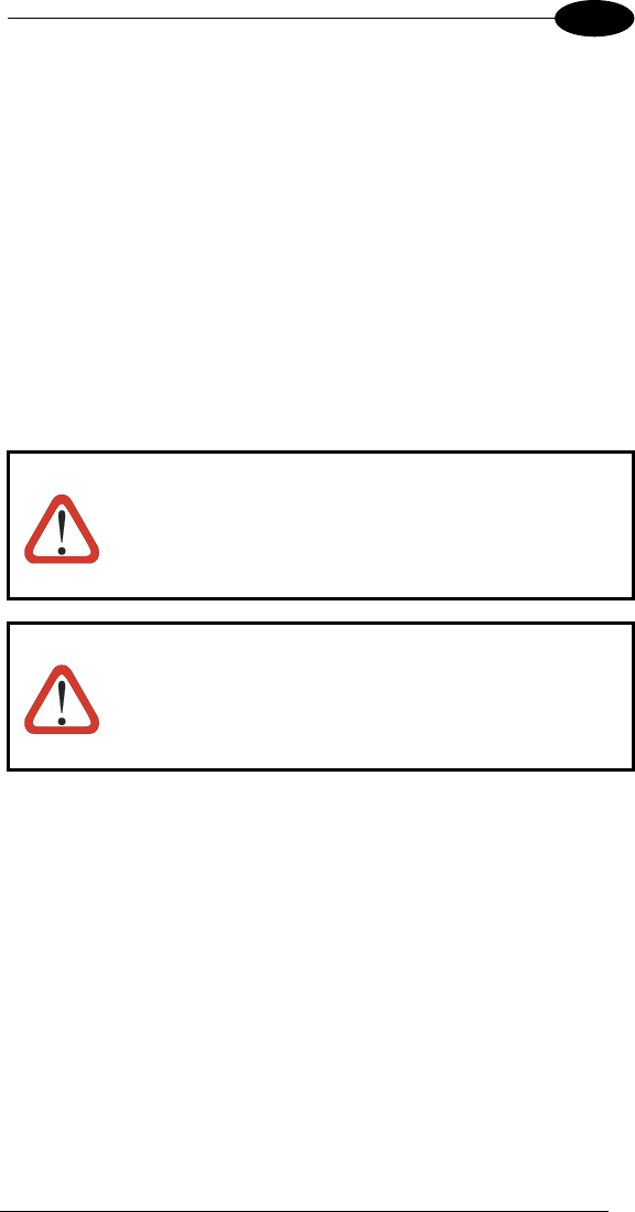
USE AND FUNCTIONING
37
3
3.9 FIRMWARE UPDATE
The Datalogic Joya™ is equipped with a tool that implements a firmware update
service.
This tool, called Datalogic Updater (DLUpdater), is compatible with all
hardware versions of the following WindowsCE 5.0 models:
Datalogic Skorpio™;
Datalogic Jet™;
Datalogic Kyman™;
Datalogic Joya™
Datalogic Memor™.
The DLUpdater, that is automatically invoked at startup, searching for a
potential update file (DLUpdate.bin). If it finds it, it proceeds to update only the
components that are damaged or not updated. An update can be explicitly
invoked by running the application DLUpdater.exe, provided together with the
update file. The update must be contained in folder “\BACKUP”.
CAUTION
It is advisable, even if not binding, to connect the terminal to
an external power source before starting the update
process. This prevents the terminal from turning off while
running and avoids a corruption of flash content.
CAUTION
After the update process, all the data stored in the backup
folder could be irreparably lost, as well as the device
configuration (even that one stored in persistent memory).
Therefore, before starting a firmware update it is advisable
to run a backup copy of the data you want to preserve on
PC (e.g. using ActiveSync).
Retrieving a Firmware Image Update
The following instructions use Internet Explorer to retrieve the most current
firmware image.
1. Launch Internet Explorer on your PC and navigate to
www.mobile.datalogic.com.
2. Navigate the Downloads section of the web site.
3. Select the product, desired language, and software updates. Click Go!
4. Select the file you want to download, then click Save and navigate to the
location where you want to save the firmware files.
5. Click Save again to begin copying the files to your local machine (or local
network location).
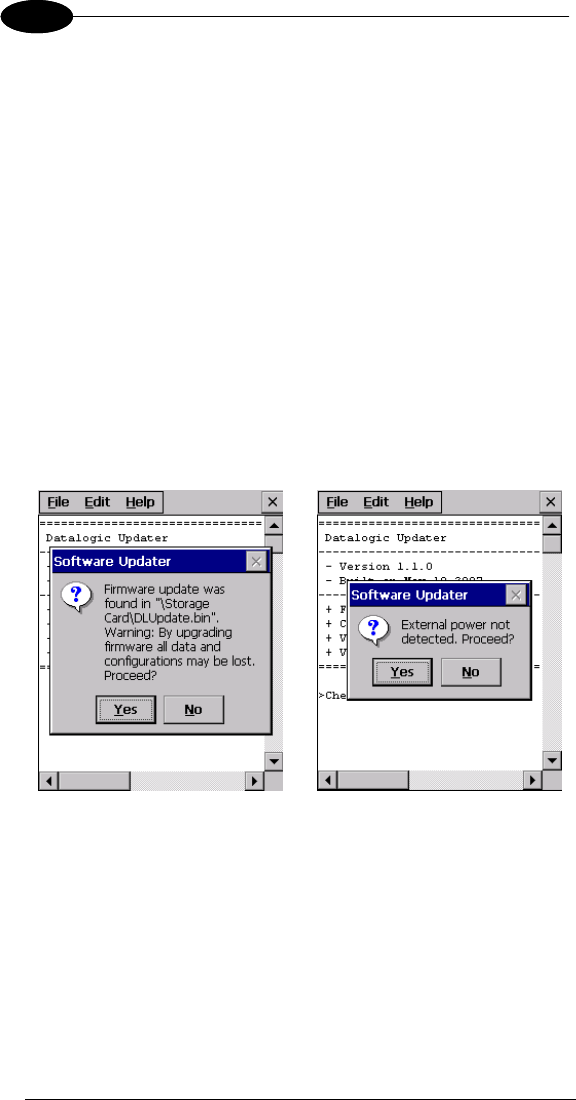
DATALOGIC JOYA™
38
1 3
Firmware Update Procedure
1. Download the update from the web site (see previous par.). It is a zip file
containing the files:
• DLUpdater.exe – that starts the update;
• DLUpdate.bin – binary file containing the updated firmware;
2. Copy the files DLUpdater.exe (optional) and DLUpdate.bin in folder
“\BACKUP”.
3. Open the folder “\BACKUP” on the terminal and run DLUpdater.exe
(double tap the icon).
4. The message shown in figure 1 will come up on the screen. It informs that
DLUpdater found a firmware update in “\BACKUP\DLUpdate.bin”. It also
warns the user that by proceeding with the terminal firmware upgrade all
data and configurations (registry) may be lost. Select <YES> to continue,
<NO> to cancel operations.
5. DLUpdater detects whether an external power source is present. If not, a
warning will come up on the screen asking for a confirmation before
carrying on (see figure 2).
Figure 1 Figure 2
7. DLUpdater performs all the necessary operations of check, update and
verify and, if no errors occur during the update, terminates the running
invoking a cold boot of the terminal, so that the update process could be
completed.
8. Following the operating system upgrade, the message shown in figure 3
may come up at the terminal startup. It informs the user that a flash disk
formatting (folder \backup) would required for a clean update and asks
whether to proceed with this operation. Select <YES> to format the flash
disk. Select <NO> to preserve the current data stored in the backup folder.
Sometimes the update process may force a flash format. In these cases
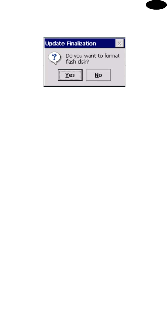
USE AND FUNCTIONING
39
3
the data stored in the backup folder will be irreparably lost. It is therefore
recommended to run a backup of the data you want to preserve before
starting a firmware update.
Figure 3
DATALOGIC JOYA™
40
1 4
4 MAINTENANCE
NOTE
Battery packs are not initially charged. Therefore the initial
operation to perform is to charge them. See below.
CAUTION
By default, the battery pack is disconnected at the factory to
avoid damage due to excessive draining.
Annual replacement of rechargeable battery pack avoids
possible risks or abnormalities and ensures maximum
performance.
4.1 CHARGING THE BATTERY PACK
The battery pack autonomy varies according to factors, such as the frequency
of barcode scanning, RF usage, etc.
The battery icon on the Taskbar indicates when the battery pack is low.
It is also possible to recharge the battery pack by using a Joya Cradle.
Moreover recharging is possible by USB Direct connection with the host
computer, but with longer charging times and in this case it is advised to keep
the mobile computer off.
NOTE
The battery pack autonomy varies according to many factors,
such as the frequency of barcode scanning, RF usage, battery
life, storage, environmental conditions, etc.
CAUTION
If the battery pack is new or has not been recharged for a
long time, it is necessary to perform two or three charging
and discharging cycles (complete use) before it can reach
its maximum charge capability.
The maximum time required to recharge a completely run-
down standard battery pack is about 3 hours.
NOTE
Even if the storage temperature range is wider, In order to
achieve the longest battery life, store the terminal and the
spare batteries between 20 to 30 ºC (68 to 86 ºF).
The Batteries must be charged at a temperature ranging
from 0° to +45 °C (+32° to +113 °F).
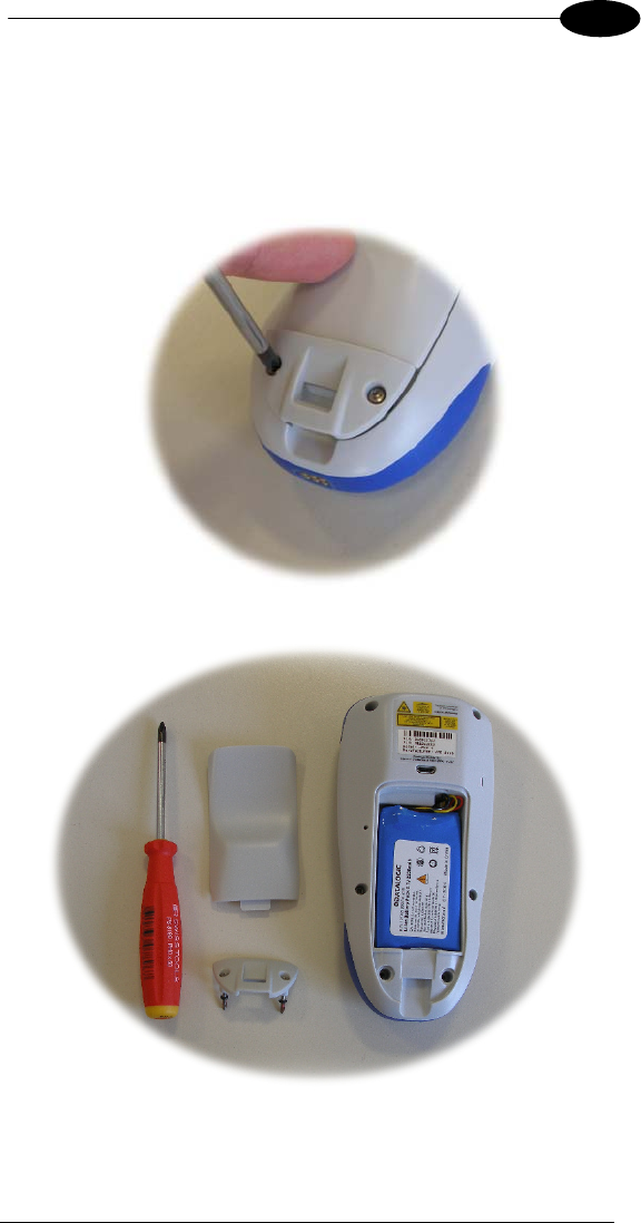
MAINTENANCE
41
4
4.2 REPLACING THE BATTERY PACK
To correctly replace the battery pack, proceed as follows.
1. Unscrew the two screws placed on the back bottom. The battery pack
cover is now released.

DATALOGIC JOYA™
42
1 4
2. Remove the cover and then the battery pack, using the proper plastic strip.
Pay attention when disconnecting the connector.
3. Install the new battery pack, first insert the connector respecting the right
way, then the upper side, finally the bottom side, leaving the plastic strip
available for future replace.
4. For correct locking, first insert the upper part of the battery cover, then the
lower and rotate the screws to the horizontal position.

MAINTENANCE
43
4
WARNING
To install, charge and/or do any other action on the battery,
follow this manual.
The battery pack may get hot, explode, ignite, and/or cause
serious injury if exposed to abusive conditions.
If the battery pack is replaced with an improper type, there is risk
of explosion.
Do not place the battery pack in or near a fire or heat; do not
place the battery pack in direct sunlight, or use or store the
battery pack inside unventilated areas in hot weather; do not
place the battery pack in microwave ovens, dryer, high pressure
containers, on induction cookware or similar device. Doing so
may cause the battery pack to generate heat, explode or ignite.
Using the battery pack in this manner may also result in a loss of
performance and a shortened life expectancy.
Use only a Datalogic Mobile approved power supply. The use of
an alternative power supply will void the product warranty, may
cause product damage and may cause heat, explode or ignite.
The area in which the units are charged should be clear of debris
and combustible materials or chemicals.
Do not use the battery pack of this terminal for power devices
different from this mobile computer.
Immediately discontinue use of the battery pack if, while using,
charging or storing the battery pack, the battery pack emits an
unusual smell, feels hot, changes colour or shape, or appears
abnormal in any other way.
Do not short-circuit the battery pack contacts connecting the
positive terminal and negative terminal. This might happen, for
example, when you carry a spare battery pack in your pocket or
purse; accidental short–circuiting can occur when a metallic
object such as a coin, clip, or pen causes direct connection of
the contacts of the battery pack (these look like metal strips on
the battery pack). Short–circuiting the terminals may damage the
battery pack or the connecting object.
Do not apply voltages to the battery pack contacts.
Do not pierce the battery pack with nails, strike it with a hammer,
step on it or otherwise subject it to strong impacts or shocks.
Do not disassemble or modify (i.e. bend, crush or deform) the
battery pack. The battery pack contains safety and protection
devices, which, if damaged, may cause the battery pack to
generate heat, explode or ignite.
DATALOGIC JOYA™
44
1 4
WARNING
In case of leakage of liquid from the battery, avoid contact with
liquid the skin or eyes. If the contact occurs, immediately wash
the affected area with water and consult a doctor.
Do not solder directly onto the battery pack.
Do not expose the battery pack to liquids.
Avoid any knocks or excessive vibrations. If the device or the
battery is dropped, especially on a hard surface, you should take
it to the nearest Authorised Repair Centre for inspection before
continuing to use it.
Do not replace the battery pack when the device is turned on.
Do not remove or damage the battery pack’s label.
Do not use the battery pack if it is damaged in any part.
Battery pack usage by children should be supervised.
Collect and recycle waste batteries separately from the device in
comply with European Directive 2006/66/EC, 2002/95/EC,
2002/96/EC and subsequent modifications, US and China
regulatory and others laws and regulations about environment.
NOTE
In order to guarantee an adequate operating autonomy,
when replacing the battery pack the mobile computer
checks the battery energy level. If the battery is not
sufficiently charged, Datalogic Joya™ does not turn on.
In this case, either substitute the battery pack with a
charged one (sufficiently charged) or insert Datalogic
Joya™ into a powered cradle or plug it into the direct power
supply.
NOTE
To achieve the best battery life, turn off the radios not in
use.
4.3 CLEANING THE MOBILE COMPUTER
Periodically clean the Datalogic Joya™ with a slightly dampened cloth.

JOYA CRADLE DISPENSER
45
5
5 JOYATM CRADLE DISPENSER
5.1 INTRODUCTION
JoyaTM Cradle Dispenser has the following responsibilities:
to recognize the insertion and extraction of the Joya
to control the blocking device
to signal status using the LEDs
to supply power to the Joya for battery recharging
Joya Cradle Dispenser has three Joya slots, each equipped with its own
control unit, an electromechanical system for blocking/releasing the
terminal, notification light, battery power and recharging circuits.
Its special structure makes it possible to design any type of dispenser (wall-
mounted or island) easily, allowing twice the number of terminals to be installed
per vertical square meter with respect to the competing systems.
5.2 ACCESSORIES
91ACC1000 Power Supply 12V 300W
91ACC0730 Power Junction Cable I90x/3 Cradle (8 pcs.)
91ACC0650 Term. Unlock Magnets (5 pcs.)
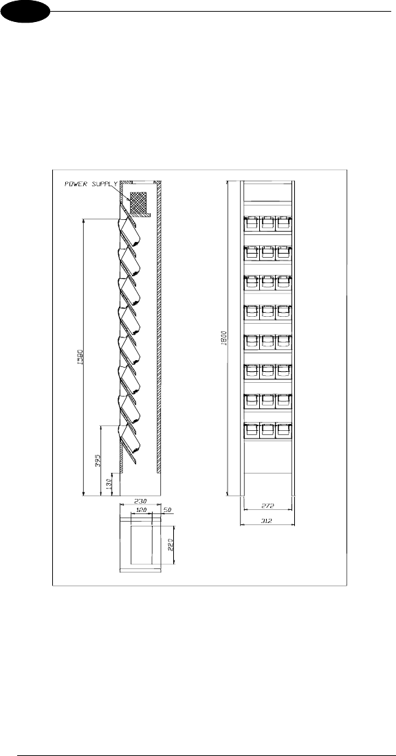
DATALOGIC JOYA™
46
1 5
5.3 INSTALLATION REQUIREMENTS
The figure below represents an 8 Joya Cradle Dispenser Base Unit organized in
a single column.
Joya will be inserted into the Cradle Dispensers are at a minimum height of
approximately 40 cm. from the floor and a maximum height of about 160 cm.
from the floor.
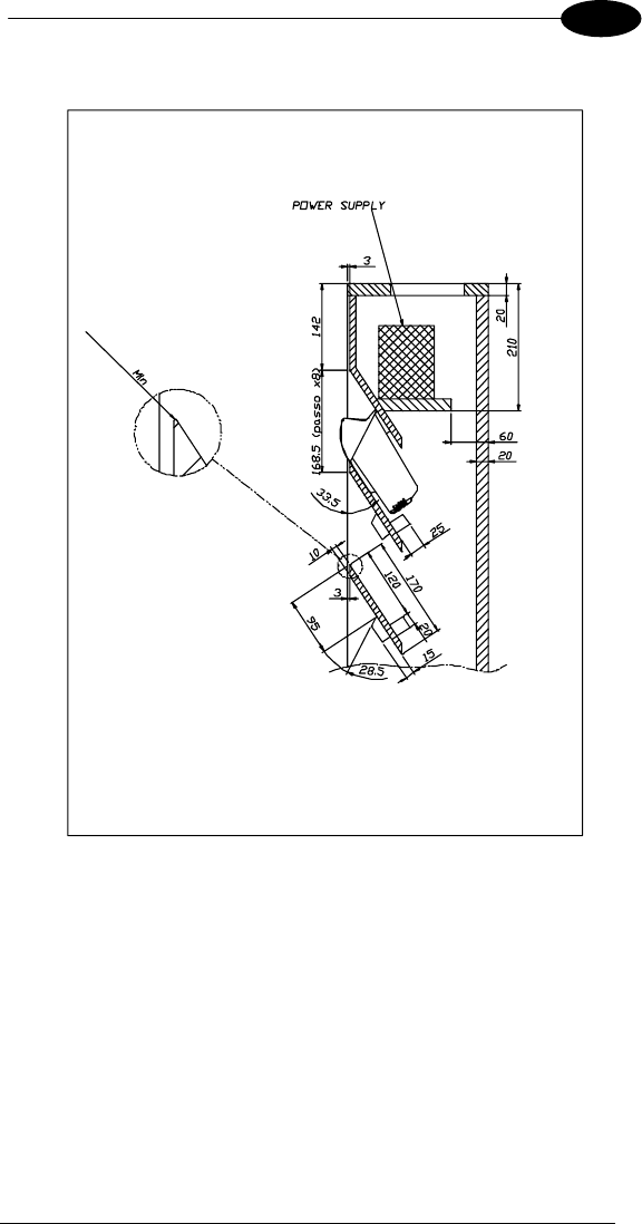
JOYA CRADLE DISPENSER
47
5
5.3.1 Base Unit Construction Details
All of the dimensional quotes necessary for building and correctly mounting the
supporting crosspieces and fixing blocks for the Joya Cradle Dispensers are
indicated.
The zoom of the upper edge of the supporting crosspiece indicates the
necessity of reducing the radius of this edge as much as possible in order to
provide a stable contact surface for the upper cover of the Joya Cradle
Dispenser.
The power supply shelf is positioned so that it guarantees a sufficient volume of
air flow for the cooling of the power supplies.
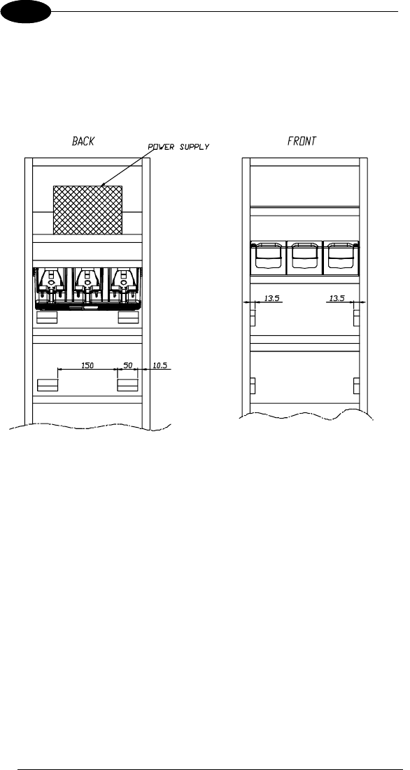
DATALOGIC JOYA™
48
1 5
Suggestion:
The cradle fixing blocks shown in the figures are mounted to the supporting
crosspieces under the Joya Cradle Dispensers. Their purpose is to prevent the
Joya Cradle Dispensers from falling inside the cabinet during the mounting
phase in which the Joya Cradle Dispensers may not be correctly positioned
before fixing them.
5.3.2 JoyaTM Cradle Dispenser Supports
Joya Cradle Dispensers are supported inside the Base Unit from crosspieces
fixed to the side panels of the cabinet. The front part of each Joya Cradle
Dispenser cover rests on the upper edge of its supporting crosspiece, while the
back part rests on two fixing blocks attached to the crosspiece above it.
Joya Cradle Dispenser is mounted to the cabinet using two screws that are
inserted into the holes provided towards the back of its cover and screwed into
the corresponding holes in the fixing blocks..
To correctly position Joya Cradle Dispensers, the supporting crosspieces and
the fixing blocks must be mounted according to the dimensional quotes and the
angles.

JOYA CRADLE DISPENSER
49
5
5.3.3 Internal Cabinet Space and Openings
The space between the rear of the Joya Cradle Dispensers and the back part of
the cabinet must be left for two reasons:
• it must be possible to retrieve objects that accidentally fall through the
cradles from the floor behind the cabinet.
• there must be a zone for air to freely circulate behind the Joya Cradle
Dispensers to aid their cooling during operation.
For these reasons the cabinet must not be closed at the bottom and must have
an opening at the top. To allow retrieval of objects that could accidentally fall
into the cabinet, it is necessary to leave space between the lower edge of the
lowest crosspiece and the floor. This space must be a compromise between the
necessity of allowing object retrieval and the necessity of prohibiting access
behind the cabinet.
5.3.4 Anchoring and Maintenance Issues
The cabinet must be anchored to the wall in at least two points, since the
contact surface area on the floor is small and therefore not sufficient to
guarantee full stability.
Suggestion:
It is preferable for the cabinet to have a removable back panel for easy access
inside when performing cabling.
The top of the cabinet should also be removable for access to the power
supplies during maintenance without the necessity of removing the cabinet from
the anchoring points to the wall. For this reason the power supplies should also
be able to be mounted and removed from the top of the cabinet.
5.3.5 Power Supply Positioning and Cooling
At the top of the cabinet there must be an opening not small. This opening
generates a natural convection effect allowing the flow of air to remove heat
generated by the Joya Cradle Dispensers during their operation.
The power supplies, or single power supply must be mounted on their shelf in
the upper part of the cabinet.
This position for the power supplies has been chosen to aid the flow of air inside
the cabinet taking advantage of natural convection. The hot air generated by the
power supplies, in fact, leaves through the opening at the top and takes in
cooler air from the lower part of the cabinet.
The power supplies therefore must be placed on the shelf in such a way as not
to block the flow of air coming up from the lower part of the cabinet.
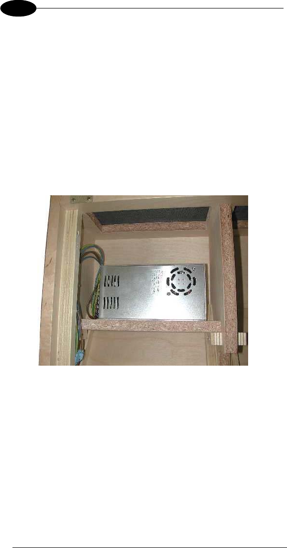
DATALOGIC JOYA™
50
1 5
The opening at the top of the cabinet must be covered with a grill or mesh,
which allows air to flow freely but protects against access to the inside of the
cabinet. In this way the power supplies can not be reached externally.
Power Supplies
• a single 300 W power supply capable of supplying all 8 Cradle
Dispensers (91ACC1000 Power Supply 12V 300W).
The power supplies must be mounted inside the cabinet onto their shelves so
that the necessary air flow for cooling the Joya Cradle Dispensers below is not
limited. In addition, the openings on the power supplies must not be obstructed
at any time, which could impede correct cooling.
If the power supplies are mounted using angular brackets, use the threaded
holes provided on the power supply case. Make sure that the mounting screws
are size M4 and do not penetrate the power supply case by more than 5.5 mm.
5.3.6 AC Power Cabling
Connection of the Power Supply to the AC line must be made using a cable
having characteristics that meet the Safety Normatives currently in force.
The cable must have an earth ground wire that is connected to the earth ground
terminal of the power supply.
The cable must have wire dimensions that meet or exceed the nominal current
and power specifications of the power supply to which it is connected.
There must be a cable clamp applied to the power cable where it enters the
cabinet, which meets the Safety Normatives currently in force.
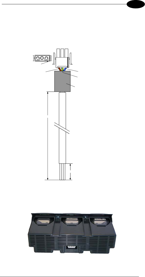
JOYA CRADLE DISPENSER
51
5
5.3.7 Wiring
To wire the Joya Cradle Dispensers, pre-wired power junction cables are
provided as accessories (91ACC0730 Power Junction Cable I90x/3 Cradle -8
pcs.), which are ready to be connected to the power connector at the bottom of
the Joya Cradle Dispenser.
3 2 1
BLUE
Connector: AMP 1-480700-0
Contacts: AMP 350536-1
Series: UNIVERSAL MATE-N-LOCK
Ferrite: RICHCO RRH120-056-300
Cable: flexible flameproof 3-wire stranded
individual wire diameter = 1 mm²
300 mm
40 mm
BROWN
Y
ELLOW-GREEN
3 2 1
Key
To connect the Joya Cradle Dispensers to the power supplies, the pre-wired
junction cables must be connected to three multi-strand copper wires (singly or
incorporated in a cable) and these must be connected to the power supply
terminals.

DATALOGIC JOYA™
52
1 5
These wiring connections must be made with particular care and meet or
exceed the nominal current and power specifications; the current flowing
through them is 2.5 A per Joya Cradle Dispenser. The wires must meet the
Safety Normatives currently in force.
The following table indicates the maximum current specifications for some wire
conductor sections according to the EN 60950 Electrical Safety Normative.
Maximum Current Wire Section
10 A 1 mm²
16 A 1.5 mm²
25 A 2.5 mm²
Suggestion:
It is advised to use a cable made up of two groups of three-conductor multi-
stranded wire with flame retardant insulation (single or together in a cable with
flame retardant insulation) having a copper wire section equal to 1.5 mm².
The two groups of three conductors are connected to the output terminals of the
power supplies: in the case of two power supplies, one group of wires is
connected to one power supply and the other group is connected to the other
power supply; in the case of a single power supply, both groups of wires are
connected to the same power supply.
Each three conductor cable group must be used to connect four of the Joya
Cradle Dispensers mounted in the Base Unit via their junction cables.
Joya Cradle Dispenser junction cables can be connected to the three-conductor
cable groups using IDC connectors having a maximum current capability not
less than 3 A.
5.3.8 Cable to Power Supply Connection
All 12 Vdc power supply connections, both the main power cable and the power
junction cables must be made according to the following requirements:
Power Junction Cable
Wires Connection Designation
Brown +12V +V
Blue ground -V
Yellow-Green earth ground FG or
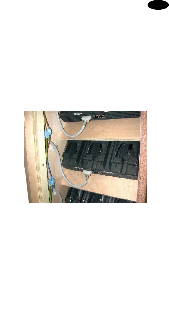
JOYA CRADLE DISPENSER
53
5
5.3.9 Affixing Cables to Cabinet
The ends of the junction cables that are connected to the main cable groups
must be affixed to the cabinet sides so as to guarantee the following conditions:
• it must be possible to extract the Joya Cradle Dispenser from the front of
the cabinet while the cable is connected so that the connector can be
plugged in or out of the Cradle Dispenser from outside the cabinet.
• when the Joya Cradle Dispenser is mounted in the cabinet, its cable
must be laid against the supporting crosspiece so that it does not block
objects which may accidentally fall through the Cradle Dispenser into the
inside of the cabinet.
Next image shows an example of affixing the Cradle Dispenser cables to the
cabinet. The Cradle Dispenser cables are connected to the main power cables
through IDC connectors.
5.3.10 Safety Precautions
Joya Cradle Dispenser Cabinet, the relative electrical wiring and connection to
the AC power line must be made according to the Safety Normatives currently
in force.
The following paragraphs contain some particularly important considerations to
keep in mind.
• Cradle Dispenser Operating Temperature
Joya Cradle Dispensers are designed and built to operate within the following
environmental conditions:
Operating Temperature Range: 10 to 30 °C
Storage Temperature Range: -20 to 60 °C

DATALOGIC JOYA™
54
1 5
Humidity: 90% non condensing
• Cabinet
The cabinet must not have any exposed sharp edges, which could represent a
danger to customers.
The requirements for air passages to cool both the JoyaCradle Dispensers and
the power supplies must be adhered to in order to avoid overheating problems
for the components inside the cabinet.
All components having dangerous voltage levels must be protected from
unauthorized access. Only qualified personnel should be authorized access for
maintenance purposes.
In particular, the opening at the top of the cabinet must be closed with a grill or
mesh that prevents access from the outside to the power supplies below. In
addition, the plastic protection covers must be mounted over the power supply
terminals to avoid accidental contact by maintenance personnel when the
cabinet is open.
• Wiring
The wires used for cabling must have flame retardant insulation.
The cables must be affixed to the cabinet avoiding types of cable clamps that
use screws or have moving parts that press directly upon the cable itself. Cable
clamps must also be applied close to the wires coming from the power supplies
so that they won't be accidentally pulled out of the power supply terminals to
which they are connected.
Avoid running cables with sharp bends or that rest on sharp edges which can
damage them over time and in the long run pose a danger inside the cabinet.
After making all the wiring connections, if some connections have wire exposed
without insulation, they must be insulated.
5.3.11 Connection to AC Line Voltage
If connection to the AC power line is made with a plug at the end of the cable,
The outlet to which it is inserted must be close by and easily accessible. The
outlet must also be rated for the maximum power consumption, which can be
considered equal to the nominal power of the connected power supplies.
If the Terminal Distributor is connected in a fixed electrical plant, a circuit
breaker must be provided in order to completely disconnect the AC line voltage
form the Cradle Dispenser cabinet. This circuit breaker must be positioned
close to the cabinet and be easily accessible. It must also be rated for the
maximum power consumption and must meet the Safety Normatives currently in
force.
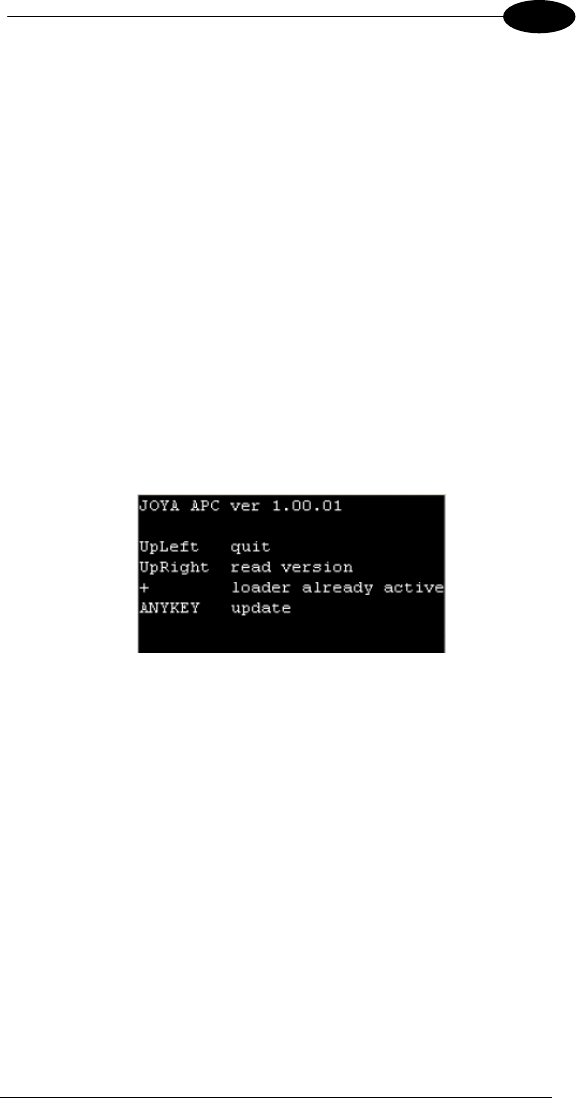
JOYA CRADLE DISPENSER
55
5
5.4 JOYATM CRADLE DISPENSER FIRMWARE
Joya Cradle Dispenser is provided with a full operational Firmware, therefore it
doesn’t require any kind of software devoloping activitiy Instead, the behaviour
of the Joya Cradle Dispenser could be controlled at high level using the Joya.
In SDK Tools is furnished APC.exe program, to upgrade Joya Cradle Dispenser
firmware release.
5.4.1 APC installation
By using ActiveSync copy in the \BACKUP folder the following files:
• APC.EXE (executable)
• APC_EN.xml (english language help)
• CpodC2.HEX (cradle’s latest firmware provided by Datalogic Mobile
s.r.l.)
5.4.2 Starting program
Run APC.exe application:
The screen displays the APC version and the mode to interact with the cradle
(read or write).
• The upper left key close the application and come back to Windows
CE
• The plus key (upper centre key) is reserved.
• The upper right key read the current version of firmware
• Any other keys put APC to the writing mode.
When application runs USB cable can be disconnected.
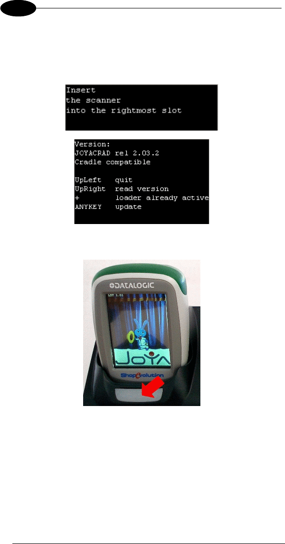
DATALOGIC JOYA™
56
1 5
5.4.3 Reading firmware version
Select the “Read version” by pressing the upper-right key. APC will display the
message on the left. Insert in any cradle’s slot and the result will look as the
right picture.
Cradle locks terminal in the slot, the terminal top flashes three times. At the end
approach a magnet to the sensitive area to unlock and extract the terminal.
If user does not insert Joya into a slot, a timeout message is displayed asking to
remake the operation.
In case of errors a suitable message is displayed.
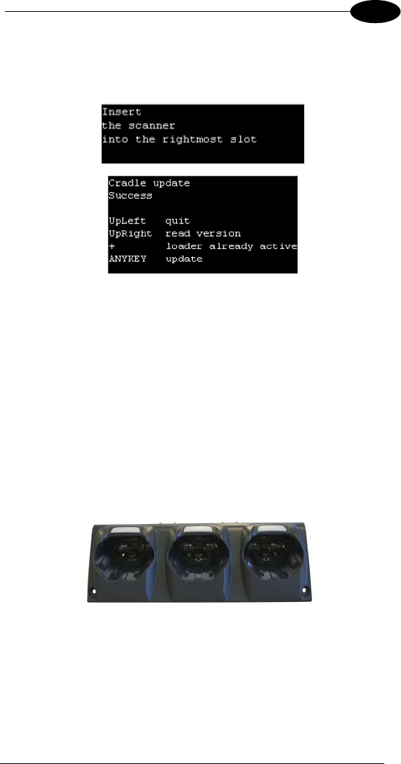
JOYA CRADLE DISPENSER
57
5
5.4.4 Firmware update procedure
Select “Update” from main menu and insert the terminal into the rightmost slot
of the cradle.
The cradle locks the terminal and APC transfers firmware, during this period slot
leds flashes. At the end the terminal top flashes three times, approach a magnet
to the sensitive area to unlock and extract the terminal.
APC shows a suitable message to inform user if update is correctly completed
or an error has been occurred.
5.5 JOYATM – JOYATM CRADLE DISPENSER
CONNECTION
Joya Cradle Dispenser is equipped with an electrical-serial connection, used to
exhange command and response with Joya. The communications between the
terminal inserted into the slot and the slot itself, are performed by means of a
special “RPC like commad-response” protocol.
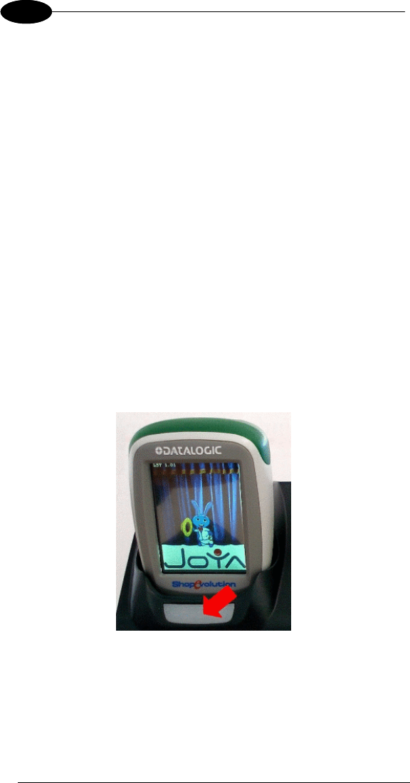
DATALOGIC JOYA™
58
1 5
5.6 CONFIGURATION
Joya Cradle Dispenser should be previously configured using an apposite
program: ABC.exe (see SDK Help for more information).
In a typical application there is the need to identify in a unique way each cradle
slot, in order to be able to perform selective operations. This requirement is
satisfied by each Joya Cradle Dispenser slot, by means of a set of four
parameters, called Config Parameters:
Slot ID: is a string of 2 bytes
Dispenser ID: is string of 1 byte
IP address: is a string of …bytes
Port ID: is a string of 2 bytes
Using this four byte strings it is possible to setup and identifiy each slot in a
unique way.
This Config Parateters are stored in the permanent memory location dedicated
of each slot. They can be configured making use of the ABC companion tool
and they can be read by a well inserted Joya.
5.7 USE AND FUNCTIONING
Insert a Joya inside a slot, Joya Cradle Dispenser will lock the Joya, when
electrical connectors are contacted.
To unlock Joya, approach a magnet to the sensitive area and extract the Joya.
All other commands could be developed by devolopers using Joya SDK.
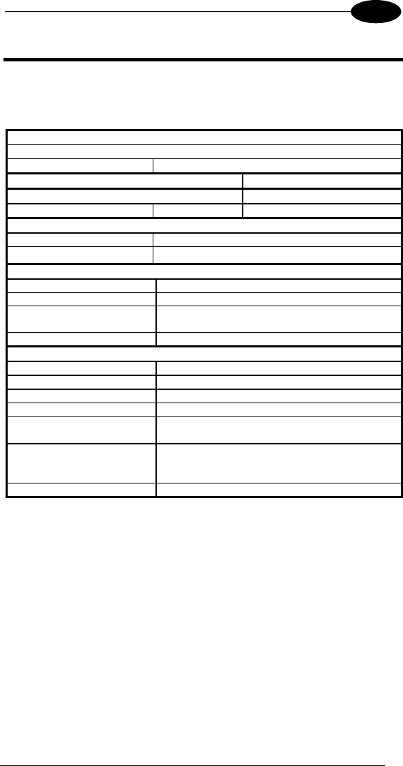
JOYA/JOYA+ TECHNICAL FEATURES
59
6
6 JOYATM/JOYA+TM TECHNICAL FEATURES
6.1 TECHNICAL DATA
Datalogic JoyaTM/Joya+ Common Features
Electrical Features
Power
Battery Pack 2 cell Li-Pol 2200 mAh@3.7 V (nominal)
Communication Features Windows CE COM Port
Bluetooth® Interface**** COM5
Serial Interface USB 1.1 COM6
Wireless Features
WLAN IEEE 802.11b/g WiFi
WPAN Bluetooth® IEEE 802.15, Class 2, Version 1.2
Environmental Features
Working Temperature* 0° to +50 °C / 32 °F to +122 °F
Storage Temperature -20° to +70 °C / -4° to +158 °F
Humidity** 10 to 80% non condensing
for temperatures < 38 °C
Drop Resistance*** 1.2 m / 3,9 ft
Hardware Features
FLASH 128 MB
RAM 128 MB
Microprocessor**** Intel PXA 270 312/520 MHz
Audio**** Beeper / Polyphonic audio
LEDs**** Datalogic Green Spot
Top & bottom Lighting Bumper
Display**** TFT LCD 65K Color, 2.8”, with 320 x 240 pixel
resolution (QVGA), with LED backlight and
touch screen
Keyboard**** 6 fully programmable keys; backlight feature
* Battery must be charged at a temperature ranging from 0° to +45 °C.
Close to the limits of the working temperature, some display and/or battery performance
degradation may occur.
** Multiple rapid humidity and/or temperature variations may cause condensing.
*** Multiple drops can permanently damage the device.
**** PXA 270 520 Mhz, polyphonic audio, bottom lighting bumper, touch screen, keyboard
backlight and Bluetooth® Interface only on JOYA+ model

DATALOGIC JOYA™
60
1 6
Mechanical Features
Dimensions (LxWxH) 149 x 73 x 44 mm
Weight 255 g (incl. battery)
Programming Features
Operating system Windows CE 5.0
Laser Optical Features
Light source laser scanner Visible laser diode - laser class 2
Scan rate 100 scans/sec
Safety class Class II EN 60825-1
Decoding features
Decoded barcodes 1D GS1 Databar, UPC-EAN, Code 39, Two-of-five,
Plessey, Codabar, Code 128, Code 11, Code
93, MSI

TEST CODES
61
7
7 TEST CODES
High Density Codes
0.25 mm (10 mils)
Code 39
!17162H!
17162
2/5 Interleaved
Ë"8NduÌ
0123456784
Code 128
ÌtestwÎ
test
80%
EAN 13 x(0B2DE5*KKKKLM(
80%
EAN 8 (6450*TRMN(

DATALOGIC JOYA™
62
1 7
Medium Density Codes
0.38 mm (15 mils)
Code 39
!17162H!
17162
Interleaved 2/5
Ë"8NduÌ
0123456784
Code 128
ÌtestwÎ
test
100%
EAN 13 x(0B2DE5*KKKKLM(
100%
EAN 8 (6450*TRMN(

TEST CODES
63
7
Low Density Codes
0.50 mm (20 mils)
Code 39
!17162H!
17162
Interleaved 2/5
Ë"8NduÌ
0123456784
Code 128
ÌtestwÎ
test
120%
EAN 13 x(0B2DE5*KKKKLM(
120%
EAN 8 (6450*TRMN(

64
GLOSSARY
Access Point
A device that provides transparent access between Ethernet wired networks
and IEEE 802.11 interoperable radio-equipped mobile units. Hand-held mobile
computers, PDAs or other devices equipped with radio cards, communicate with
wired networks using Access Points (AP). The mobile unit (mobile computer)
may roam among the APs in the same subnet while maintaining a continuous,
seamless connection to the wired network.
Barcode
A pattern of variable-width bars and spaces which represents numeric or
alphanumeric data in binary form. The general format of a barcode symbol
consists of a leading margin, start character, data or message character, check
character (if any), stop character, and trailing margin. Within this framework,
each recognizable symbology uses its own unique format.
Baud Rate
A measure for data transmission speed.
Bit
Binary digit. One bit is the basic unit of binary information. Generally, eight
consecutive bits compose one byte of data. The pattern of 0 and 1 values within
the byte determines its meaning.
Bluetooth®
A standard radio technology using a proprietary protocol. The onboard
Bluetooth® module in the mobile computer is compatible with the 1.1 protocol.
Byte
On an addressable boundary, eight adjacent binary digits (0 and 1) combined in
a pattern to represent a specific character or numeric value. Bits are numbered
from the right, 0 through 7, with bit 0 the low-order bit. One byte in memory can
be used to store one ASCII character.
Decode
To recognize a bar code symbology (e.g., Codabar, Code 128, Code 3 of 9,
UPC/EAN, etc.) and analyze the content of the bar code scanned.
EEPROM
Electrically Erasable Programmable Read-Only Memory. An on-board non-
volatile memory chip.
Flash Disk
Non-volatile memory for storing application and configuration files.
Host

65
A computer that serves other mobile computers in a network, providing services
such as network control, database access, special programs, supervisory
programs, or programming languages.
Liquid Crystal Display (LCD)
A display that uses liquid crystal sealed between two glass plates. The crystals
are excited by precise electrical charges, causing them to reflect light outside
according to their bias. They use little electricity and react relatively quickly.
They require external light to reflect their information to the user.
Light Emitting Diode (LED)
A low power electronic light source commonly used as an indicator light. It uses
less power than an incandescent light bulb but more than a Liquid Crystal
Display (LCD).
RAM
Random Access Memory. Data in RAM can be accessed in random order, and
quickly written and read.
RF
Radio Frequency.
RTC
Real Time Clock.

66
INDEX
A
Accessories; 2
ActiveSync® Remote; 31
B
Backup Directory File
Management; 36
Bluetooth® Manager Device
Setup; 32
C
Charging the Batteries; 40
Cleaning the Mobile Computer; 44
Connections; 3
Control Panel; 18
Conventions; vii
D
Data Capture; 9
Laser Data Capture; 9
Data Capture Configuration; 13
Datalogic Joyar™ Description; 1
Default Settings; 16
Description of the Keys; 10
E
End User License Agreement; v
F
Files Admin; 20
Firmware Update; 37
FTP Server Setup; 35
G
General View; xix
Glossary; 64
J
JoyaTM cradle dispenser; 45
L
Laser Safety; ix
M
Maintenance; 40
Microsoft® ActiveSync®; 30
Model Description; 1
P
Package Contents; 2
Patents; xvii
R
Radio Compliance; xiv
Reader Parameters; 15
Reference Documentation; vii
References; vii
Registry; 18
Replacing the Batteries; 41
Resetting the Joya™; 11
S
Safe Setup; 20
Safety Regulations; viii
Save Session; 20
Scan Parameters; 15
Startup; 7
Status Indicators; 12
Stylus Calibration; 28
Summit Radio Card; 23
T
Taskbar; 12
Technical Features; 59
Test Codes; 61
U
USB Connection; 3
Using the Stylus; 8
W
WEEE Compliance; xvii
Windows Connections; 30
Wireless Communications; 22
WLAN Connection; 4
WPAN Connections; 6

Datalogic Mobile S.r.l.
Via S. Vitalino, 13
40012 - Lippo di Calderara
Bologna - Italy 08
dichiara che
declares that the
déclare que le
bescheinigt, daß das Gerät
declare que el
JOYA
e tutti i suoi modelli
and all its models
et tous ses modèles
und seine Modelle
y todos sus modelos
sono conformi alle Direttive del Consiglio Europeo sottoelencate:
are in conformity with the requirements of the European Council Directives listed below
sont conformes aux spécifications des Directives de l’Union Européenne ci-dessous:
der nachstehend angeführten Direktiven des Europäischen Rats:
cumple con los requisitos de las Directivas del Consejo Europeo, según la lista siguiente:
1999/5/EEC R&TTE
Questa dichiarazione è basata sulla conformità dei prodotti alle norme seguenti:
This declaration is based upon compliance of the products to the following standards:
Cette déclaration repose sur la conformité des produits aux normes suivantes:
Diese Erklärung basiert darauf, daß das Produkt den folgenden Normen entspricht:
Esta declaración se basa en el cumplimiento de los productos con la siguientes normas:
ETSI EN 301 489-17 v1.2.1, August 2002: ELECTROMAGNETIC COMPATIBILITY AND R
A
DIO SPECTRUM
MATTERS (ERM); ELECTROMAGNETIC COMPATIBILTY (EMC)
STANDARD FOR RADIO EQUIPMENT AND SERVICES; PART 17:
SPECIFIC CONDITIONS FOR 2,4GHZ WIDEBAND
TRANSMISSION SYSTEMS AND 5GHZ HIGH PERFORMANCE
RLAN EQUIPMENT
ETSI EN 300 328 v1.7.1, October 2006: ELECTROMAGNETIC COMPATIBILITY AND R
A
DIO SPECTRUM
MATTERS (ERM); WIDEBAND TRANSMISSION SYSTEMS;
DATA TRANSMISSION EQUIPMENT OPERATING IN THE 2,4GHZ
ISM BAND AND USING WIDE BAND MODULATION
TECHNIQUES; HARMONIZED EN COVERING ESSENTIAL
REQUIREMENTS UNDER ARTICLE 3.2 OF THE R&TTE
DIRECTIVE
EN 60950-1, December 2001: INFORMATION TECHNOLOGY EQUIPMENT – SAFETY –
PART 1: GENERAL REQUIREMENTS
EN 50392:2004 GENERIC STANDARD TO DEMONSTRATE THE COMPLIANCE
OF ELECTRONIC AND ELECTRICAL APPARATUS
WITH THE BASIC RESTRICTIONS RELATED TO HUMAN
EXPOSURE TO ELECTROMAGNETIC FIELDS (0 HZ – 300
GHZ)
Lippo di Calderara, December 12th, 2008
Paola Chientaroli
Quality Assurance Manager

Datalogic Mobile S.r.l.
Via S. Vitalino, 13
40012 - Lippo di Calderara
Bologna - Italy 08
dichiara che
declares that the
déclare que le
bescheinigt, daß das Gerät
declare que el
Joya Cradle Dispenser
e tutti i suoi modelli
and all its models
et tous ses modèles
und seine Modelle
y todos sus modelos
sono conformi alle Direttive del Consiglio Europeo sottoelencate:
are in conformity with the requirements of the European Council Directives listed below
sont conformes aux spécifications des Directives de l’Union Européenne ci-dessous:
der nachstehend angeführten Direktiven des Europäischen Rats:
cumple con los requisitos de las Directivas del Consejo Europeo, según la lista siguiente:
89/336/EEC EMC Directive e 92/31/EEC, 93/68 /EEC emendamenti successivi
and further amendments
et ses successifs amendements
und späteren Abänderungen
y succesivas enmiendas
Basate sulle legislazioni degli Stati membri in relazione alla compatibilità elettromagnetica ed
alla sicurezza dei prodotti.
On the approximation of the laws of Member States relating to electromagnetic compatibility
and product safety.
Basée sur la législation des Etats membres relative à la compatibilté électromagnétique et à la
sécurité des produits.
Über die Annäherung der Gesetze der Mitgliedsstaaten in bezug auf elektromagnetische
Verträglichkeit und Produktsicherheit entsprechen.
Basado en la aproximación de las leyes de los Países Miembros respecto a la compatibilidad
electromagnética y las Medidas de seguridad relativas al producto.
Questa dichiarazione è basata sulla conformità dei prodotti alle norme seguenti:
This declaration is based upon compliance of the products to the following standards:
Cette déclaration repose sur la conformité des produits aux normes suivantes:
Diese Erklärung basiert darauf, daß das Produkt den folgenden Normen entspricht:
Esta declaración se basa en el cumplimiento de los productos con la siguientes normas:
EN 55022 ( CLASS B ITE ), SEPTEMBER 1998:
INFORMATION TECHNOLOGY EQUIPMENT
RADIO DISTURBANCE CHARACTERISTICS
LIMITS AND METHODS OF MEASUREMENTS
EN 55024, SEPTEMBER 1998:
AMENDMENT A1, OCTOBER 2001
AMENDMENT A2, JANUARY 2003
INFORMATION TECHNOLOGY EQUIPMENT
IMMUNITY CHARACTERISTICS
LIMITS AND METHODS OF MEASUREMENT
Lippo di Calderara, December 12th, 2008
Paola Chientaroli
Quality Assurance Manager