Datalogic 0016 Kyman-Net User Manual pre Kyman NET Master
Datalogic SpA Kyman-Net pre Kyman NET Master
UserManual.wiki
>
Datalogic
>
0016 User Manual
>
User Manual
Contents
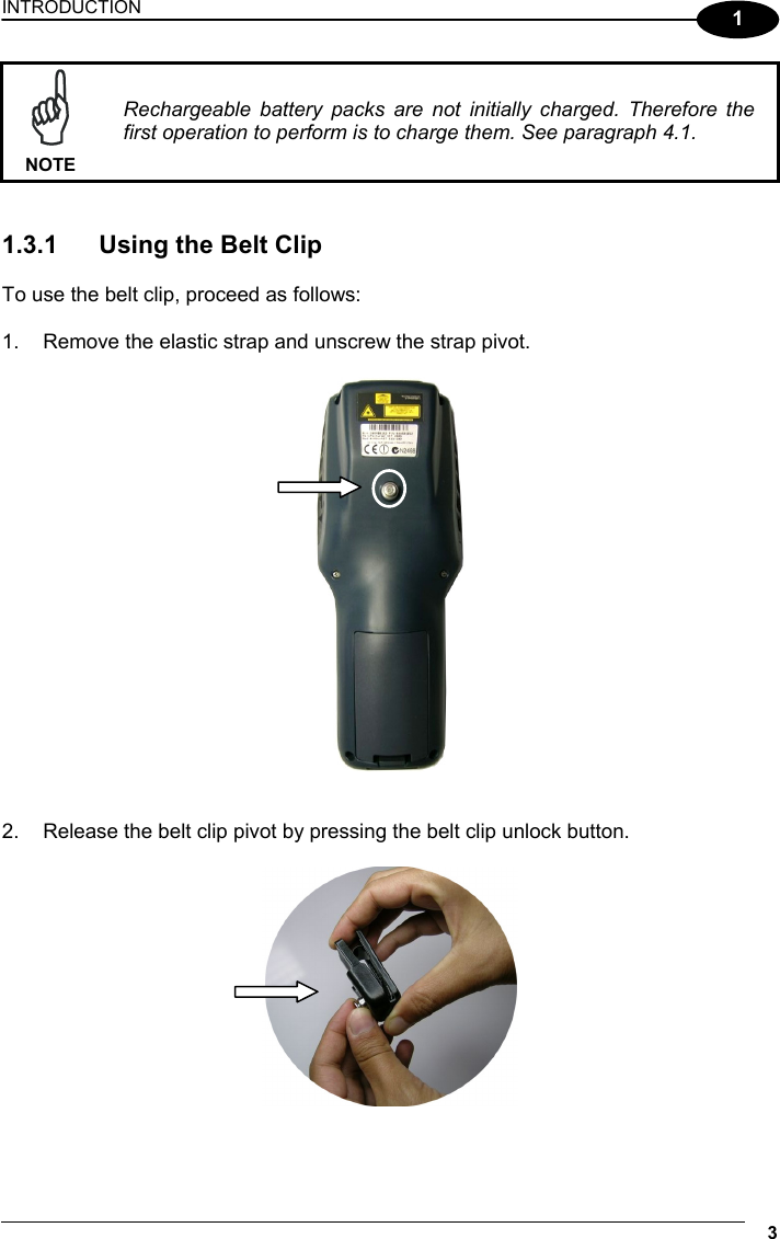
1.
User Manual
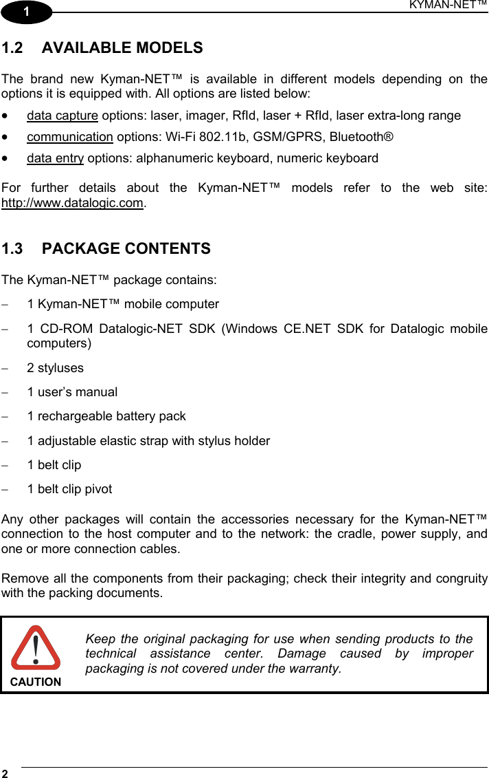
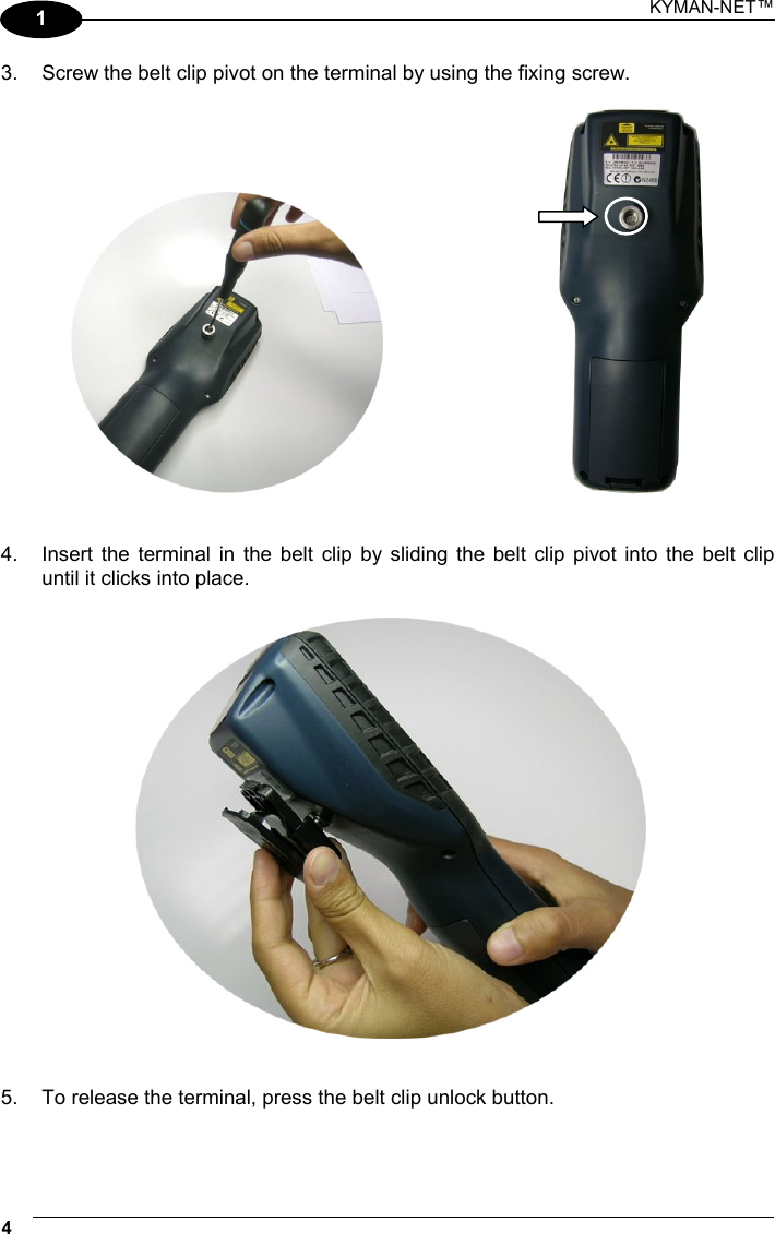
2.
Users Manual
User Manual
Navigation menu
Upload a User Manual
Namespaces
Wiki Guide
HTML
PDF
Info
Views
User Manual
Discussion / Help
Navigation

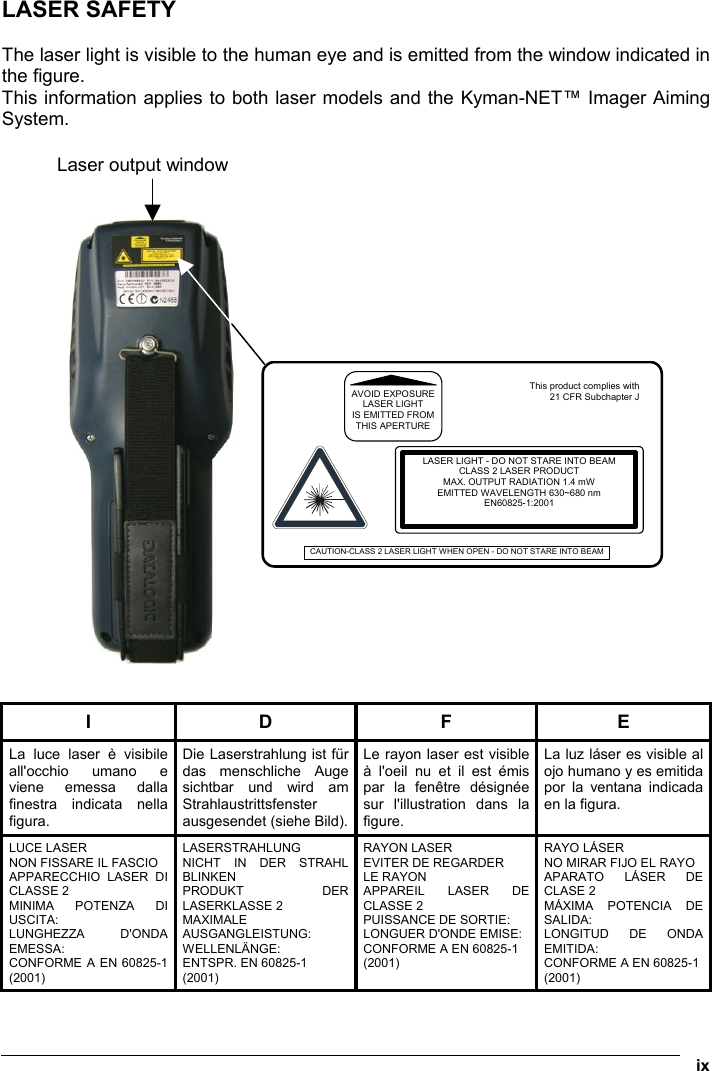

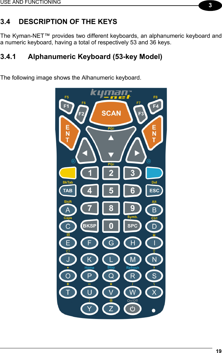
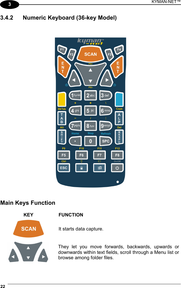
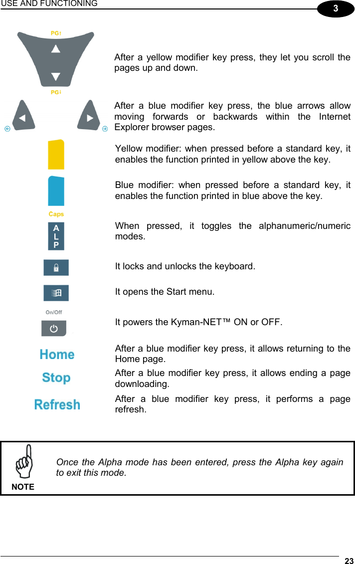
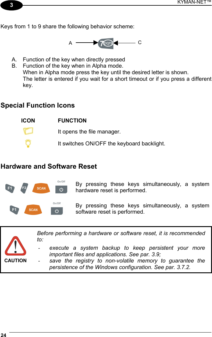
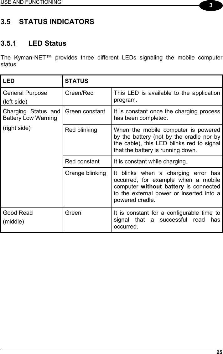
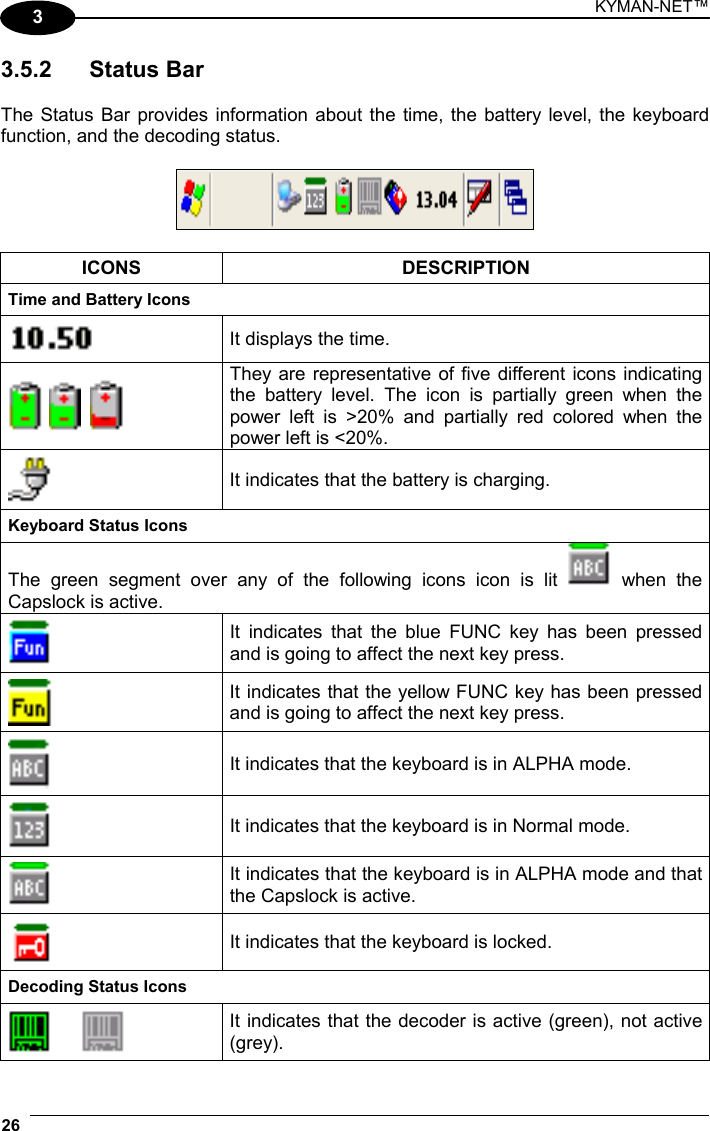
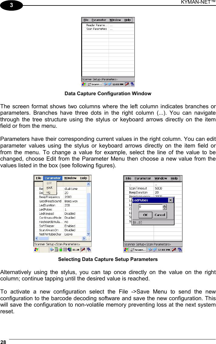
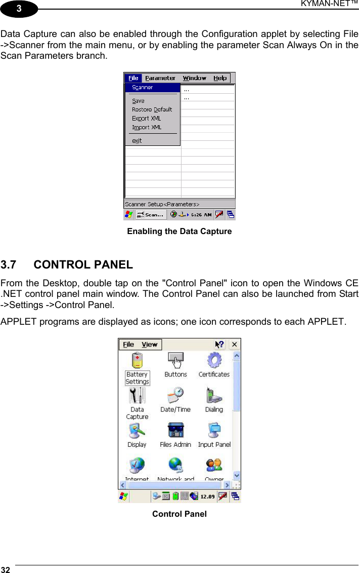
![KYMAN-NET™ 14 3 3 USE AND FUNCTIONING The use of the Kyman-NET™ depends on the application software loaded. However there are several parameters that can be set and utilities that can be used to perform some basic functions such as data capture, communications, file management, etc. 3.1 STARTUP The Kyman-NET™ turns on when the battery pack or the external supply is inserted. After the battery pack is installed, use the [ON/OFF] key to turn the mobile computer on and off. As soon as the mobile computer is on, the Windows CE .NET desktop configuration will appear on the screen. Wait a few seconds before starting any activity so that the mobile computer completes its startup procedure. Use the stylus as suggested in paragraph 3.2 to select icons and options.](https://usermanual.wiki/Datalogic/0016.User-Manual/User-Guide-699080-Page-30.png)
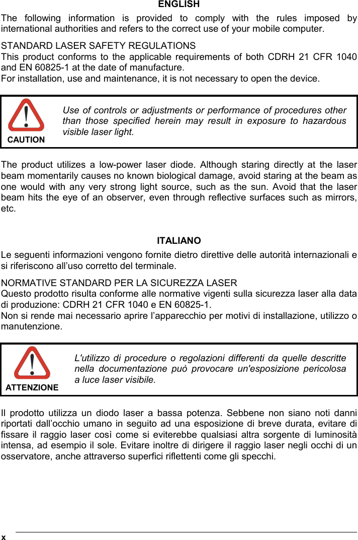
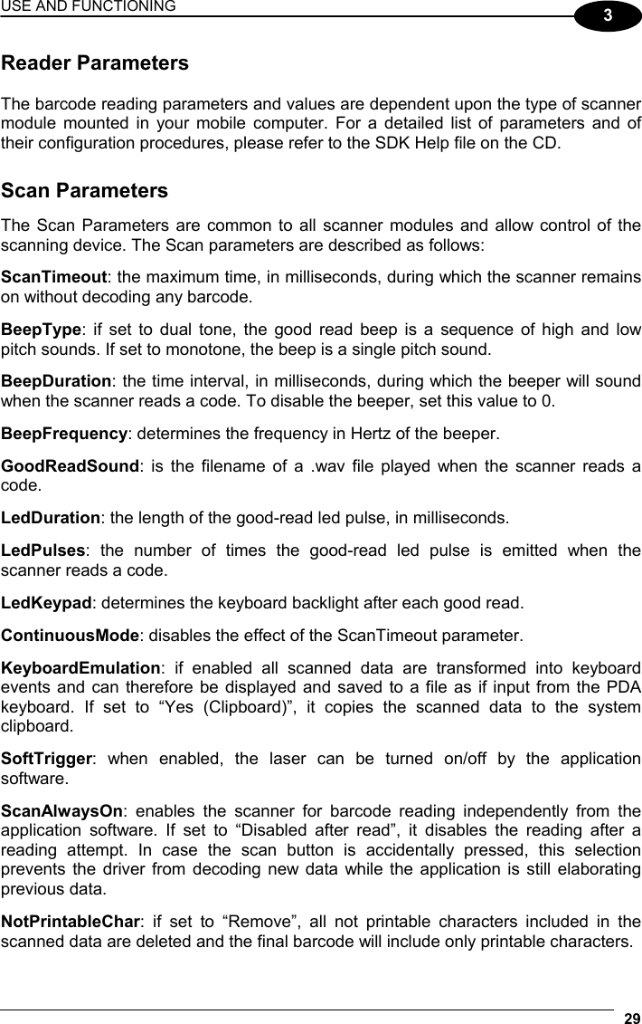
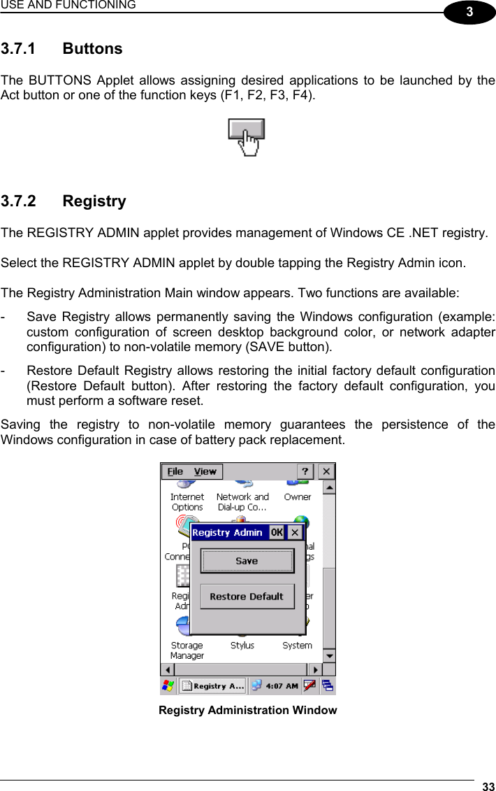
![USE AND FUNCTIONING 15 3 The mobile computer goes into power-off (low power with display and keyboard backlight off), when it is no longer used for more than a programmable timeout, which is defined in the POWER applet of the Control Panel. In this mode it can be awakened (resuming operation) by the [ON/OFF] key. NOTE The mobile computer can also be awakened or turned off by the application program. 3.2 USING THE STYLUS The stylus selects items and enters information. The stylus functions like a mouse. Tap: Touch the screen once with the stylus to open items and select options. Drag: Hold the stylus on the screen and drag across the screen to select text and images. Drag in a list to select multiple items. Tap-and-hold: Tap and hold the stylus on an item to see a list of actions available for that item. On the pop-up menu that appears, tap the action you want to perform. The stylus is factory aligned; however, it is possible to align the cursor on the screen with the tip of the stylus. Enter the STYLUS applet of the Control Panel and tap the center of each target that appears on the screen with the tip of the stylus.](https://usermanual.wiki/Datalogic/0016.User-Manual/User-Guide-699080-Page-31.png)
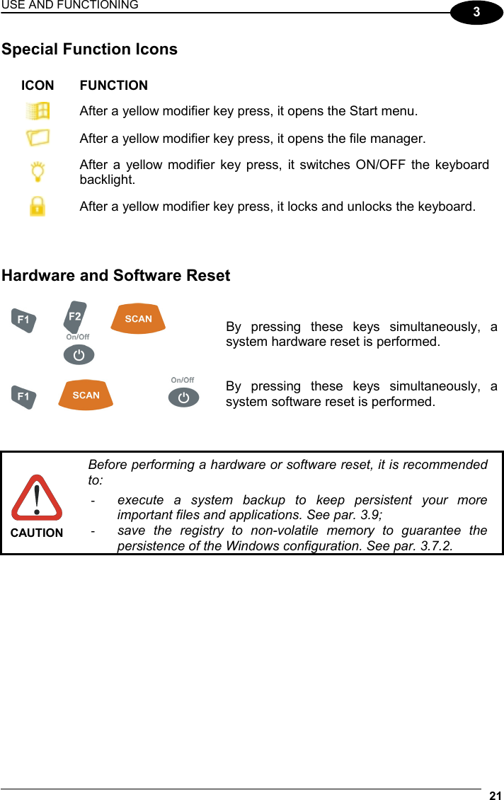

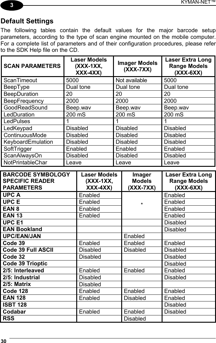
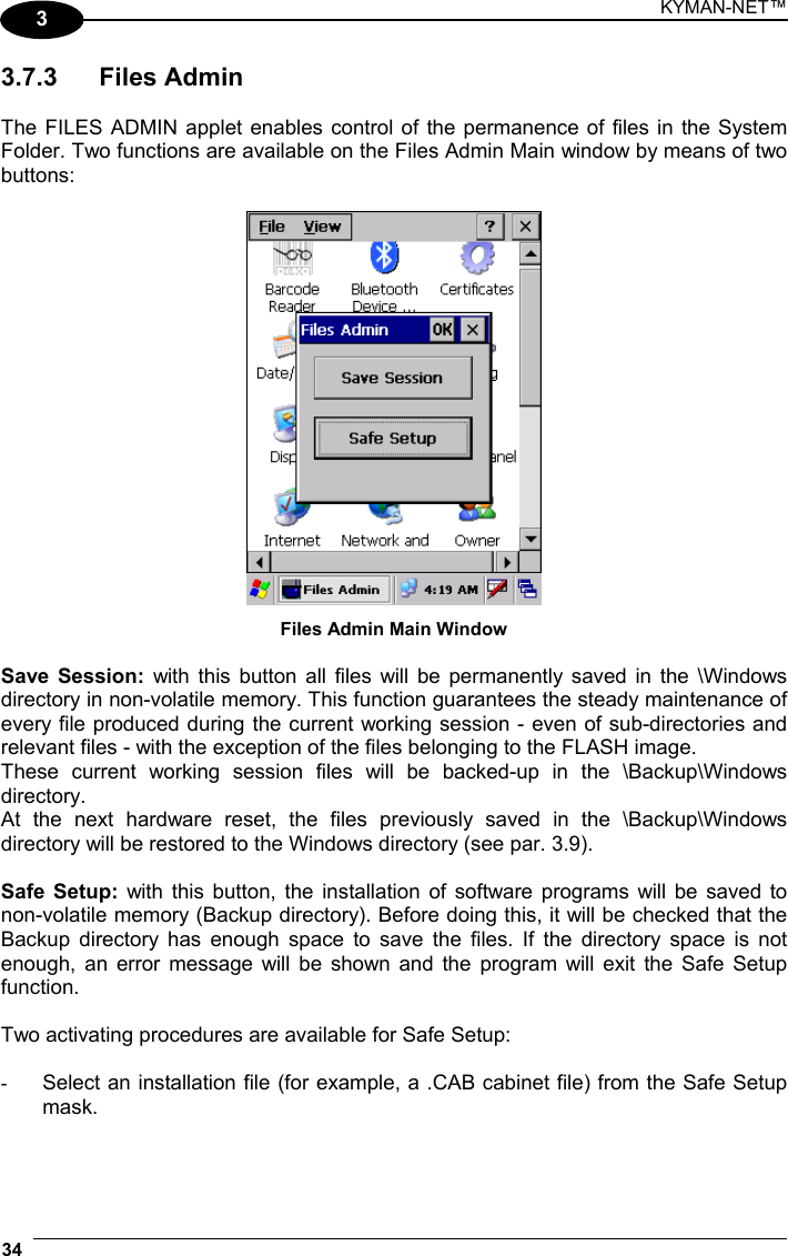
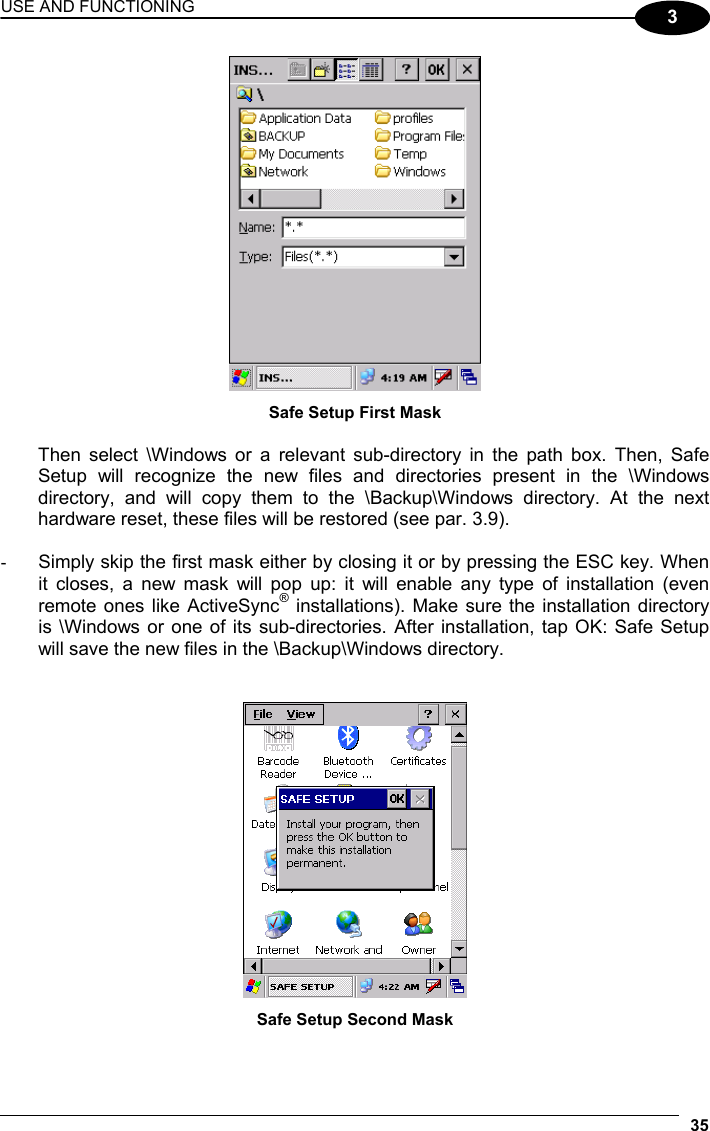
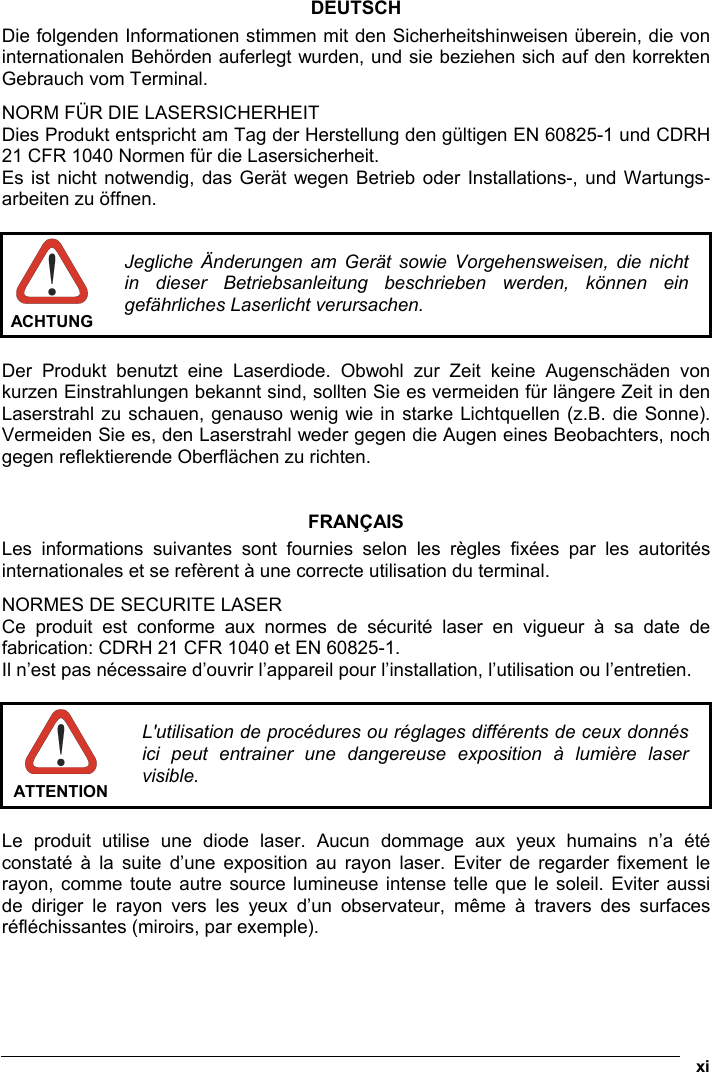
![USE AND FUNCTIONING 45 3 3.9 BACKUP DIRECTORY FILE MANAGEMENT All of the Windows CE .NET system files reside in RAM (volatile memory) except for the Backup directory, which resides in FLASH (non-volatile memory). Therefore the contents of the Backup directory are persistent even if the mobile computer is re-booted or the battery pack is changed. You can save your more important files that you don't want to lose due to mobile computer re-boot, in the Backup directory or create a sub-directory within Backup. Even though the Windows Directory resides in RAM, it often contains files or sub-directories created by the user or by installation programs that you don't want to lose at re-boot. To keep these files persistent it is necessary to copy them to the directory \Backup\Windows. This directory doesn't exist originally (only Backup exists), and therefore it must be created. At the next hardware reset, before activating the shell, Windows CE .NET will copy the contents including all sub-directories of \Backup\Windows to \Windows. Likewise, to maintain files that must be run at Windows CE .NET startup, (i.e. .exe, .lnk, .vb, .htm, etc.), it is necessary to copy them to the directory \Backup\Startup. This directory does not exist originally (only Backup exists), and therefore it must be created. The application programs will be run after any type of re-boot (both software and hardware reset). As an alternative to the Safe Setup function, it is possible to copy the .cab files to the directory \Backup\Cabfiles (the Cabfiles sub-directory doesn't exists originally and must therefore be created) and perform a mobile computer cold boot to have the application installed. Once these files are copied to the directory \Backup\Cabfiles, the application will be run after each re-boot. From the second cold boot on, a message may be displayed such as "<application name> is already installed. Re-install?". This message blocks the boot process. Press the [Enter] key to continue the system initialization.](https://usermanual.wiki/Datalogic/0016.User-Manual/User-Guide-699080-Page-61.png)