Datalogic 0016 Kyman-Net User Manual pre Kyman NET Master
Datalogic SpA Kyman-Net pre Kyman NET Master
Contents
- 1. User Manual
- 2. Users Manual
User Manual

Kyman-NET™
USER'S MANUAL

DATALOGIC S.p.A.
Via Candini 2
40012 - Lippo di Calderara di Reno
Bologna - Italy
Kyman-NET™ - User's Manual
Ed.: 06/2006
ALL RIGHTS RESERVED
Datalogic reserves the right to make modifications and improvements without prior notification.
Datalogic shall not be liable for technical or editorial errors or omissions contained herein, nor for incidental or
consequential damages resulting from the use of this material.
Product names mentioned herein are for identification purposes only and may be trademarks and or
registered trademarks of their respective companies.
© Datalogic S.p.A. 2004-2006

iii
CONTENTS
DATALOGIC END USER LICENSE AGREEMENT..................................... v
REFERENCES ........................................................................................... vii
Conventions.................................................................................................vii
Reference Documentation ...........................................................................vii
Services and Support...................................................................................vii
SAFETY REGULATIONS.......................................................................... viii
General Safety Rules.................................................................................. viii
Laser Safety..................................................................................................ix
Radio Compliance....................................................................................... xiii
Information for the User .............................................................................. xiii
FCC COmpliance........................................................................................xiv
WEEE Compliance .....................................................................................xiv
GENERAL VIEW ........................................................................................ xv
1 INTRODUCTION .......................................................................................... 1
1.1 Kyman-NET™ Description............................................................................ 1
1.2 Available Models........................................................................................... 2
1.3 Package Contents......................................................................................... 2
1.3.1 Using the Belt Clip ........................................................................................ 3
1.4 Accessories................................................................................................... 5
2 CONNECTIONS ........................................................................................... 6
2.1 Connection to the Host Computer................................................................. 6
2.1.1 RS232/USB Direct Connection ..................................................................... 6
2.1.2 WLAN Connection ........................................................................................ 7
2.1.3 WPAN Connections ...................................................................................... 8
2.1.4 WWAN Connections ..................................................................................... 9
2.2 Connection Cables...................................................................................... 12
3 USE AND FUNCTIONING.......................................................................... 14
3.1 Startup ........................................................................................................ 14
3.2 Using the Stylus.......................................................................................... 15
3.3 Data Capture............................................................................................... 16
3.3.1 Laser Data Capture..................................................................................... 16
3.3.2 Imager Data Capture .................................................................................. 17
3.3.3 RFID Data Capture ..................................................................................... 18
3.4 Description of the Keys ............................................................................... 19
3.4.1 Alphanumeric Keyboard (53-key Model)..................................................... 19
3.4.2 Numeric Keyboard (36-key Model) ............................................................. 22

iv
3.5 Status Indicators ......................................................................................... 25
3.5.1 LED Status.................................................................................................. 25
3.5.2 Status Bar ................................................................................................... 26
3.6 Data Capture Configuration ........................................................................ 27
3.6.1 Configure .................................................................................................... 27
3.6.2 Capture ....................................................................................................... 31
3.7 Control Panel .............................................................................................. 32
3.7.1 Buttons........................................................................................................ 33
3.7.2 Registry....................................................................................................... 33
3.7.3 Files Admin ................................................................................................. 34
3.7.4 Wireless Communications........................................................................... 36
3.7.5 Volume Settings.......................................................................................... 37
3.8 Windows Connections ................................................................................ 40
3.8.1 Microsoft® ActiveSync® ............................................................................. 40
3.8.2 Bluetooth® Manager Device Setup............................................................. 42
3.9 Backup Directory File Management ............................................................ 45
4 MAINTENANCE ......................................................................................... 46
4.1 Charging the Battery Pack .......................................................................... 46
4.2 Replacing the Battery Pack......................................................................... 47
4.3 Compact Flash and Secure Storage Cards................................................. 49
4.4 Cleaning the Mobile Computer.................................................................... 49
5 TECHNICAL FEATURES........................................................................... 50
5.1 Technical Data ............................................................................................ 50
5.2 Reading Diagrams ...................................................................................... 54
6 TEST CODES............................................................................................. 56
GLOSSARY................................................................................................ 59
INDEX......................................................................................................... 61

v
DATALOGIC END USER LICENSE AGREEMENT
BY DOWNLOADING OR INSTALLING THE SOFTWARE, OR BY USING DATALOGIC EQUIPMENT THAT
INCLUDES THIS SOFTWARE, YOU ARE CONSENTING TO BE BOUND BY THIS AGREEMENT. IF YOU
DO NOT AGREE TO ALL OF THE TERMS OF THIS AGREEMENT, THEN DO NOT DOWNLOAD, INSTALL,
USE THE SOFTWARE NOR DATALOGIC EQUIPMENT.
The following terms and conditions govern your use of the Software except to the extent that a particular program (a) is the
subject of a separate written agreement with Datalogic or (b) includes a separate “click-on” license agreement as part of the
installation and/or download process. Should a conflict arise between the provisions of the foregoing documents, the order of
precedence shall be (1) the written agreement, (2) the click-on agreement, and (3) this agreement (“Agreement”).
1. License. Subject to the terms and conditions of and except as otherwise provided in this Agreement, Datalogic S.p.A.
(“Datalogic”) and its suppliers grant to Customer (“Customer”) a nonexclusive and nontransferable license to use the specific
program modules, feature set(s) or feature(s) in object code form only as well as associated media, printed materials and
“online” or electronic documentation (the “Software”) for which Customer has paid, if required, the license fees. The Software is
licensed not sold. The license shall be subject to each of the following limitations:
• Unless otherwise expressly provided in the documentation, Customer shall use the Software solely as embedded in, for
execution on, or (where the applicable documentation permits installation on non-Datalogic equipment) for
communication with Datalogic equipment owned or leased by Customer;
• Customer’s use of the Software shall be limited to use on a single hardware chassis, on a single central processing unit,
as applicable, or use on such greater number of chassis or central processing units as Customer may have paid
Datalogic the required license fee; and
• Customer’s use of the Software shall also be limited, as applicable and set forth in Customer’s purchase order or in
Datalogic’s product catalog, user documentation, or web site, to a maximum number of (a) seats (i.e. users with access
to the installed Software), (b) concurrent users, sessions, ports, and/or issued and outstanding IP addresses, and/or (c)
central processing unit cycles or instructions per second. Customer’s use of the Software shall also be limited by any
other restrictions set forth in Customer’s purchase order or in Datalogic’s product catalog, user documentation or web site
for the Software.
2. General Limitations. Except as otherwise expressly provided under this Agreement, Customer shall have no right, and
Customer specifically agrees not to (i) transfer, assign or sublicense its license rights to any other person, or use the Software
on unauthorized or secondhand Datalogic equipment, and any such attempted transfer, assignment or sublicense shall be void;
(ii) correct errors to or otherwise modify or adapt the Software or create derivative works based upon the Software, or to permit
third parties to do the same; or (iii) decompile, decrypt, reverse engineer, disassemble or otherwise reduce the Software to
human-readable form to gain access to trade secrets or confidential information in the Software. To the extent required by law,
at Customer's request, Datalogic shall provide Customer with the interface information needed to achieve interoperability
between the Software and another independently created program, upon payment of Datalogic's applicable fee. Customer shall
observe strict obligations of confidentiality with respect to such information.
3. Upgrades and Additional Copies. For purposes of this Agreement, “Software” shall include (and the terms and conditions of
this Agreement shall apply to) any upgrades, updates, bug fixes or modified versions (collectively, “Upgrades”) or backup copies
of the Software licensed or provided to Customer by Datalogic or an authorized distributor for which Customer has paid the
applicable license fees. Notwithstanding any other provision of this Agreement: (1) customer has no license or right to use any
such additional copies or upgrades unless customer, at the time of acquiring such copy or upgrade, already holds a valid license
to the original Software and has paid the applicable fee for the upgrade, if required; (2) use of upgrades is limited to Datalogic
equipment for which customer is the original end user, purchaser or lessee or who otherwise holds a valid license to use the
Software which is being upgraded; and (3) use of additional copies is limited to backup purposes only.
4. Proprietary Notices. Customer agrees to maintain and reproduce all copyright and other proprietary notices on all copies, in
any form, of the Software in the same form and manner that such copyright and other proprietary notices are included on the
Software. Except as expressly authorized in this Agreement, Customer shall not make any copies or duplicates or any Software
without the prior written permission of Datalogic. Customer may make such backup copies of the Software as may be necessary
for Customer’s lawful use, provided Customer affixes to such copies all copyright, confidentiality, and proprietary notices that
appear on the original.
5. Protection of Information. Customer agrees that aspects of the Software and associated documentation, including the
specific design and structure of individual programs, constitute trade secrets and/or copyrighted material of Datalogic. Customer
shall not disclose, provide, or otherwise make available such trade secrets or copyrighted material in any form to any third party
without the prior written consent of Datalogic. Customer shall implement reasonable security measures to protect such trade
secrets and copyrighted material. Software and documentation shall remain solely property of Datalogic.

vi
6. Limited Warranty. If Customer obtained the Software directly from Datalogic, then Datalogic warrants that during the
Warranty Period (as defined below): (i) the media on which the Software is furnished will be free of defects in materials and
workmanship under normal use; and (ii) the Software will substantially conform to its published specifications. The “Warranty
Period” means a period beginning on the date of Customer’s receipt of the Software and ending on the later of (a) ninety (90)
days from the date of initial shipment of the Software by Datalogic, or (b) the end of the minimum period required by the law of
the applicable jurisdiction. The limited warranties extend only to Customer as the original licensee. Customer's sole and
exclusive remedy and the entire liability of Datalogic and its suppliers under these limited warranties will be, at Datalogic’s sole
option, repair or replacement of the Software if reported (or, upon request, returned) to Datalogic. Except as expressly granted
in this Agreement, the Software is provided AS IS and with all faults. Datalogic does not warrant that the Software is error free
or that Customer will be able to operate the Software without problems or interruptions. In addition, due to the continual
development of new techniques for intruding upon and attacking networks, Datalogic does not warrant that the Software or any
equipment, system or network on which the Software is used will be free of vulnerability to intrusion or attack. This warranty
does not apply if the Software (a) is licensed for beta, evaluation, testing or demonstration purposes for which Datalogic does
not receive a license fee, (b) has been altered, except by Datalogic, (c) has not been installed, operated, repaired, or maintained
in accordance with instructions supplied by Datalogic, (d) has been subjected to abnormal physical or electrical stress, misuse,
negligence, or accident, or (e) is used in ultra hazardous activities. If Customer obtained the Software from a Datalogic reseller,
the terms of any warranty shall be as provided by such distributor, and Datalogic provides Customer no warranty with respect to
such Software. The Software may contain support for programs written in Java. Java technology is not fault tolerant and is not
designed, manufactured, or intended for use or resale as online control equipment in hazardous environments requiring fail-safe
performance, such as in the operation of nuclear facilities, aircraft navigation or communication systems, air traffic control, direct
life support machines, or weapons systems, in which the failure of Java technology could lead directly to death, personal injury,
or severe physical or environmental damage. Microsoft Inc. has contractually obligated Datalogic to make this disclaimer.
7. Disclaimer of Warranties. Except as specified in this warranty, all expressed or implied conditions, representations, and
warranties including, without limitation, any implied warranty or condition of merchantability, fitness for a particular purpose, non-
infringement, satisfactory quality or arising from a course of dealing, usage, or trade practice, are hereby excluded to the extent
allowed by applicable law. To the extent that an implied warranty cannot be excluded, such warranty is limited in duration to the
warranty period.
8. Disclaimer of Liabilities. In no event will Datalogic or its suppliers be liable for any lost revenue, profit, or data, or for
special, indirect, consequential, incidental, or punitive damages however caused and arising out of the use of or inability to use
the Software even if Datalogic has been advised of the possibility of such damages. In no event shall Datalogic or its suppliers'
liability to customer, whether in contract, tort (including negligence), or otherwise, exceed the price paid by customer. The
foregoing limitations shall apply even if the above-stated warranty fails of its essential purpose.
9. Term and Termination. This Agreement is effective until terminated. Customer may terminate this Agreement at any time by
destroying all copies of Software including any documentation. Customer’s license rights under this Agreement will terminate
immediately without notice from Datalogic if Customer fails to comply with any provision of this Agreement. Upon termination,
Customer must destroy all copies of Software in its possession or control.
10. Customer Records. Customer grants to Datalogic and its independent accountants the right to examine Customer’s books,
records and accounts during Customer’s normal business hours to verify compliance with this Agreement. In the event such
audit discloses non-compliance with this Agreement, Customer shall promptly pay to Datalogic the appropriate license fees.
11. General Provisions. This Agreement shall be governed by and construed in accordance with the laws of Italy. All disputes
arising out of or in connection with this Agreement will be subject to the exclusive jurisdiction of the competent Court of the
place where Datalogic has its registered office. If any portion hereof is found to be void or unenforceable, the remaining
provisions of this Agreement shall remain in full force and effect. Except as expressly provided herein, this Agreement
constitutes the entire agreement between the parties with respect to the license of the Software and supercedes any conflicting
or additional terms contained in the purchase order.

vii
REFERENCES
CONVENTIONS
This manual uses the following conventions:
“User” refers to anyone using a Kyman-NET™ mobile computer.
“Mobile computer” and "Kyman-NET™" refer to Kyman-NET™ mobile computer.
“You” refers to the System Administrator or Technical Support person using this
manual to install, configure, operate, maintain or troubleshoot a Kyman-NET™
mobile computer.
REFERENCE DOCUMENTATION
For further information regarding Kyman-NET™ refer to the SDK Help on-Line.
SERVICES AND SUPPORT
Datalogic provides several services as well as technical support through its website.
Log on to www.datalogic.com and click on the links indicated for further information
including:
- PRODUCTS
Search through the links to arrive at your product page where you can download
specific Manuals and Software & Utilities
- SERVICES & SUPPORT
- Datalogic Services Warranty Extensions and Maintenance Agreements
- Authorised Repair Centres
- CONTACT US
E-mail form and listing of Datalogic Subsidiaries

viii
SAFETY REGULATIONS
NOTE
Read this manual carefully before performing any type of connection
to the Kyman-NET™ mobile computer.
The user is responsible for any damages caused by incorrect use of
the equipment or by inobservance of the indication supplied in this
manual.
GENERAL SAFETY RULES
− Use only the components supplied by the manufacturer for the specific
Kyman-NET™ being used.
− Do not attempt to disassemble the Kyman-NET™ mobile computer, as it does
not contain parts that can be repaired by the user. Any tampering will invalidate
the warranty.
− When replacing the battery pack or at the end of the operative life of the
Kyman-NET™ mobile computer, disposal must be performed in compliance with
the laws in force.
− Do not submerge the Kyman-NET™ in liquid products.
− For GSM models, when using the device for telephone calls, it is advised to use
a headset.
− Avoid significant and rapid temperature variations, which can produce
condensation inside the Kyman-NET™ and reduce its performance.
ix
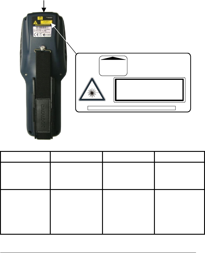
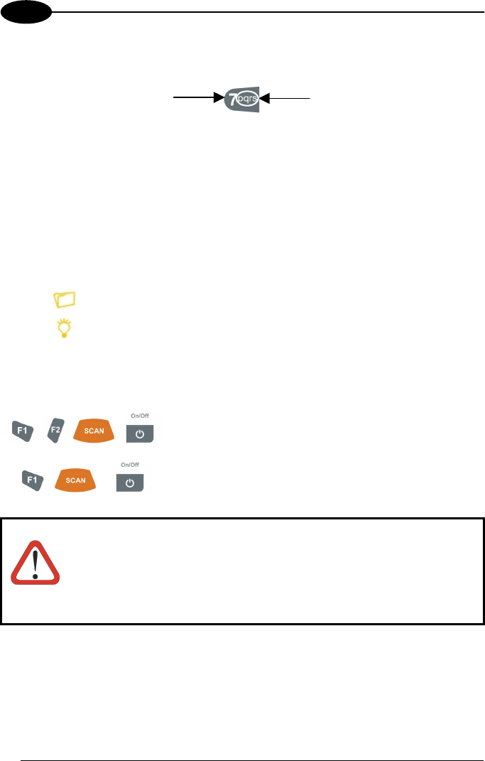
LASER SAFETY
The laser light is visible to the human eye and is emitted from the window indicated in
the figure.
This information applies to both laser models and the Kyman-NET™ Imager Aiming
System.
I D F E
La luce laser è visibile
all'occhio umano e
viene emessa dalla
finestra indicata nella
figura.
Die Laserstrahlung ist für
das menschliche Auge
sichtbar und wird am
Strahlaustrittsfenster
ausgesendet (siehe Bild).
Le rayon laser est visible
à l'oeil nu et il est émis
par la fenêtre désignée
sur l'illustration dans la
figure.
La luz láser es visible al
ojo humano y es emitida
por la ventana indicada
en la figura.
LUCE LASER
NON FISSARE IL FASCIO
APPARECCHIO LASER DI
CLASSE 2
MINIMA POTENZA DI
USCITA:
LUNGHEZZA D'ONDA
EMESSA:
CONFORME A EN 60825-1
(2001)
LASERSTRAHLUNG
NICHT IN DER STRAHL
BLINKEN
PRODUKT DER
LASERKLASSE 2
MAXIMALE
AUSGANGLEISTUNG:
WELLENLÄNGE:
ENTSPR. EN 60825-1
(2001)
RAYON LASER
EVITER DE REGARDER
LE RAYON
APPAREIL LASER DE
CLASSE 2
PUISSANCE DE SORTIE:
LONGUER D'ONDE EMISE:
CONFORME A EN 60825-1
(2001)
RAYO LÁSER
NO MIRAR FIJO EL RAYO
APARATO LÁSER DE
CLASE 2
MÁXIMA POTENCIA DE
SALIDA:
LONGITUD DE ONDA
EMITIDA:
CONFORME A EN 60825-1
(2001)
LASER LIGHT - DO NOT STARE INTO BEAM
CLASS 2 LASER PRODUCT
MAX. OUTPUT RADIATION 1.4 mW
EMITTED WAVELENGTH 630~680 nm
EN60825-1:2001
This product complies with
21 CFR Subchapter J
AVOID EXPOSURE
LASER LIGHT
IS EMITTED FROM
THIS APERTURE
CAUTION-CLASS 2 LASER LIGHT WHEN OPEN - DO NOT STARE INTO BEAM
Laser out
p
ut windo
w
x
ENGLISH
The following information is provided to comply with the rules imposed by
international authorities and refers to the correct use of your mobile computer.
STANDARD LASER SAFETY REGULATIONS
This product conforms to the applicable requirements of both CDRH 21 CFR 1040
and EN 60825-1 at the date of manufacture.
For installation, use and maintenance, it is not necessary to open the device.
CAUTION
Use of controls or adjustments or performance of procedures other
than those specified herein may result in exposure to hazardous
visible laser light.
The product utilizes a low-power laser diode. Although staring directly at the laser
beam momentarily causes no known biological damage, avoid staring at the beam as
one would with any very strong light source, such as the sun. Avoid that the laser
beam hits the eye of an observer, even through reflective surfaces such as mirrors,
etc.
ITALIANO
Le seguenti informazioni vengono fornite dietro direttive delle autorità internazionali e
si riferiscono all’uso corretto del terminale.
NORMATIVE STANDARD PER LA SICUREZZA LASER
Questo prodotto risulta conforme alle normative vigenti sulla sicurezza laser alla data
di produzione: CDRH 21 CFR 1040 e EN 60825-1.
Non si rende mai necessario aprire l’apparecchio per motivi di installazione, utilizzo o
manutenzione.
ATTENZIONE
L'utilizzo di procedure o regolazioni differenti da quelle descritte
nella documentazione può provocare un'esposizione pericolosa
a luce laser visibile.
Il prodotto utilizza un diodo laser a bassa potenza. Sebbene non siano noti danni
riportati dall’occhio umano in seguito ad una esposizione di breve durata, evitare di
fissare il raggio laser così come si eviterebbe qualsiasi altra sorgente di luminosità
intensa, ad esempio il sole. Evitare inoltre di dirigere il raggio laser negli occhi di un
osservatore, anche attraverso superfici riflettenti come gli specchi.
xi
DEUTSCH
Die folgenden Informationen stimmen mit den Sicherheitshinweisen überein, die von
internationalen Behörden auferlegt wurden, und sie beziehen sich auf den korrekten
Gebrauch vom Terminal.
NORM FÜR DIE LASERSICHERHEIT
Dies Produkt entspricht am Tag der Herstellung den gültigen EN 60825-1 und CDRH
21 CFR 1040 Normen für die Lasersicherheit.
Es ist nicht notwendig, das Gerät wegen Betrieb oder Installations-, und Wartungs-
arbeiten zu öffnen.
ACHTUNG
Jegliche Änderungen am Gerät sowie Vorgehensweisen, die nicht
in dieser Betriebsanleitung beschrieben werden, können ein
gefährliches Laserlicht verursachen.
Der Produkt benutzt eine Laserdiode. Obwohl zur Zeit keine Augenschäden von
kurzen Einstrahlungen bekannt sind, sollten Sie es vermeiden für längere Zeit in den
Laserstrahl zu schauen, genauso wenig wie in starke Lichtquellen (z.B. die Sonne).
Vermeiden Sie es, den Laserstrahl weder gegen die Augen eines Beobachters, noch
gegen reflektierende Oberflächen zu richten.
FRANÇAIS
Les informations suivantes sont fournies selon les règles fixées par les autorités
internationales et se refèrent à une correcte utilisation du terminal.
NORMES DE SECURITE LASER
Ce produit est conforme aux normes de sécurité laser en vigueur à sa date de
fabrication: CDRH 21 CFR 1040 et EN 60825-1.
Il n’est pas nécessaire d’ouvrir l’appareil pour l’installation, l’utilisation ou l’entretien.
ATTENTION
L'utilisation de procédures ou réglages différents de ceux donnés
ici peut entrainer une dangereuse exposition à lumière laser
visible.
Le produit utilise une diode laser. Aucun dommage aux yeux humains n’a été
constaté à la suite d’une exposition au rayon laser. Eviter de regarder fixement le
rayon, comme toute autre source lumineuse intense telle que le soleil. Eviter aussi
de diriger le rayon vers les yeux d’un observateur, même à travers des surfaces
réfléchissantes (miroirs, par exemple).
xii
ESPAÑOL
Las informaciones siguientes son presentadas en conformidad con las disposiciones
de las autoridades internacionales y se refieren al uso correcto del terminal.
NORMATIVAS ESTÁNDAR PARA LA SEGURIDAD LÁSER
Este aparato resulta conforme a las normativas vigentes de seguridad láser a la
fecha de producción: CDRH 21 CFR 1040 y EN 60825-1.
No es necesario abrir el aparato para la instalación, la utilización o la manutención.
ATENCIÓN
La utilización de procedimientos o regulaciones diferentes de
aquellas describidas en la documentción puede causar una
exposición peligrosa a la luz láser visible.
El aparato utiliza un diodo láser a baja potencia. No son notorios daños a los ojos
humanos a consecuencia de una exposición de corta duración. Eviten de mirar fijo el
rayo láser así como evitarían cualquiera otra fuente de luminosidad intensa, por
ejemplo el sol. Además, eviten de dirigir el rayo láser hacia los ojos de un
observador, también a través de superficies reflectantes como los espejos.
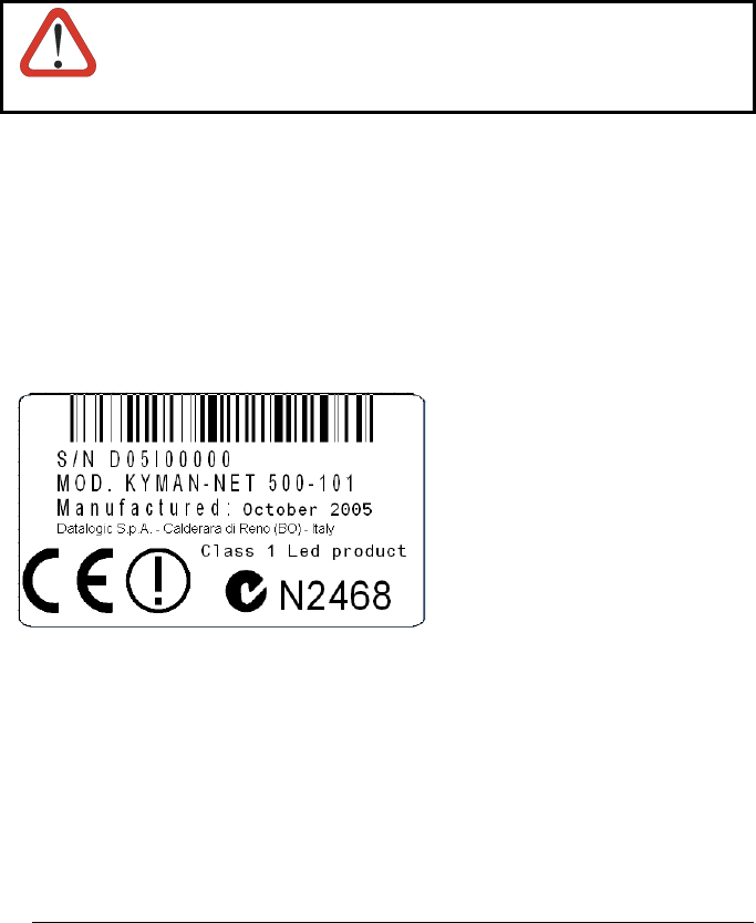
LED Illuminator
The use of an illuminator in the Kyman-NET™ Imager is a Class 1 LED product:
ILLUMINATORE LED CLASSE 1
AUSLEUCHTER LED KLASSE 1
ILLUMINATEUR A LED DE CLASSE 1
ILUMINADOR LED DE CLASE 1

xiii
RADIO COMPLIANCE
In radio systems configured with mobile computers and access points, the
frequencies to be used must be allowed by the spectrum authorities of the specific
country in which the installation takes place. Be absolutely sure that the system
frequencies are correctly set to be compliant with the spectrum requirements of the
country.
The Radio modules used in this product automatically adapt to the frequencies set by
the system and do not require any parameter settings.
The following shows the correspondence between the Kyman-NET™ models and the
Radio modules:
Kyman-NET™ 5XX-XXX 802.11b (Wi-Fi) radio card
Kyman-NET™ X1X-XXX GSM/GPRS Tri-band (900, 1800, 1900 MHz) module
Kyman-NET™ 51X-XXX 802.11b (Wi-Fi) radio card + GSM/GPRS Tri-band
(900, 1800, 1900 MHz) module
INFORMATION FOR THE USER
ENGLISH
Contact the competent authority responsible for the management of radio frequency
devices of your country to verify the eventual necessity of a user license. Refer to the
web site http://europa.eu.int/comm/enterprise/rtte/spectr.htm for further information.
ITALIANO
Prendi contatto con l'autorità competente per la gestione degli apparati a radio
frequenza del tuo paese, per verificarne l'eventuale necessità della licenza d'uso.
Inoltre puoi trovare ulteriori informazioni al sito:
http://europa.eu.int/comm/enterprise/rtte/spectr.htm.
FRANÇAIS
Contactez l'autorité compétente en la gestion des appareils à radio fréquence de
votre pays pour vérifier la nécessité du permis d'usage. Pour tout renseignement
vous pouvez vous adresser au site web:
http://europa.eu.int/comm/enterprise/rtte/spectr.htm.
DEUTSCH
Um die Notwendigkeit der Verwendungslizenz zu prüfen, wenden Sie sich an die
Behörde, die auf der Radiofrequenzgerätsführung Ihres Lands bewandert ist. Weitere
Informationen sind verfügbar auf dem Web Site:
http://europa.eu.int/comm/enterprise/rtte/spectr.htm.

xiv
ESPAÑOL
Contacta con la autoridad competente para la gestión de los dispositivos de radio
frecuencia de tu país, para verificar si es necesario la licencia de uso. Además se
puede encontrar mas información en el sitio web:
http://europa.eu.int/comm/enterprise/rtte/spectr.htm.
FCC COMPLIANCE
This device must be opened by qualified personnel only.
Modifications or changes to this equipment without the expressed written approval of
Datalogic could void the authority to use the equipment.
This device complies with PART 15 of the FCC Rules. Operation is subject to the
following two conditions: (1) This device may not cause harmful interference, and (2)
this device must accept any interference received, including interference which may
cause undesired operation.
All Wi-Fi models contain FCC ID H9PLA4137.
ALL GSM/GPRS models contain FCC ID QIPMC55.
WEEE COMPLIANCE
xv
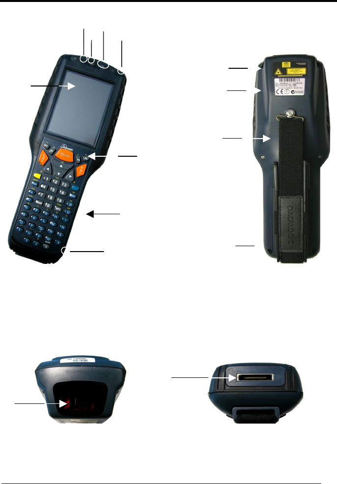
GENERAL VIEW
A) Backlit display
B) User programmable LED
C) Speaker
D) Good read LED
E) Charging status and battery low
warning LED
F) Scan key
G) Keyboard
H) Microphone
I) Laser safety label
J) Product label
K) Adjustable elastic strap with stylus
holders
L) Battery pack
M) Data capture/Laser Output window N) Communication/Charger/Headset
connector
I
J
K
L
B D
A
C E
F
G
H
M
N

xvi

INTRODUCTION
1
1
1 INTRODUCTION
1.1 KYMAN-NET™ DESCRIPTION
The Datalogic Kyman-NET™ rugged mobile computer is one of the key elements of
Datalogic’s mobile@work™ product family for logistic solutions.
Kyman-NET™, thanks to the lightest weight of its category combined with one of the
best ergonomics ever seen on the market, reduces the operators fatigue with no
compromises in terms of reliability and robustness. Its sturdy outer casing with
overmold protection has been designed to resist harsh environments, multiple drops,
strong shocks, repetitive tumbles as well as sub-zero temperatures.
Datalogic’s Kyman-NET™ key features include fully integrated automatic data
capture (1D bar code, 1D bar code & RFID HF-ISO tags, 1D & 2D bar codes &
images), allowing codes to be read from near contact to several meters distance and
simultaneous wireless communication capabilities (Bluetooth®, Wi-Fi, GSM/GPRS).
Kyman-NET™ system architecture is based on the “de-facto standard” combination
of Intel X-Scale series processors coupled with the Windows CE operating system
and it is ready to satisfy the most demanding customer needs (i.e. allowing to expand
its memory thanks to a Secure Digital standard slot).
Kyman-NET™ provides 2 intuitive keyboard layouts, numeric/alphanumeric with
backlight, able to fulfill 100% traditional text based applications (i.e. terminal
emulation, through the DL-TCL-NET™ software client) as well as the most modern
Web-based solutions (i.e. exploiting the Microsoft Internet Explorer through the DL
Locked Web Browser™ application).
Kyman-NET™ provides mobile professionals with the most relevant features needed
to operate in demanding environments: reliability, ruggedness, drop resistance, long
lasting batteries, flexible communication and efficient data capture.

KYMAN-NET™
2
1
1.2 AVAILABLE MODELS
The brand new Kyman-NET™ is available in different models depending on the
options it is equipped with. All options are listed below:
• data capture options: laser, imager, RfId, laser + RfId, laser extra-long range
• communication options: Wi-Fi 802.11b, GSM/GPRS, Bluetooth®
• data entry options: alphanumeric keyboard, numeric keyboard
For further details about the Kyman-NET™ models refer to the web site:
http://www.datalogic.com.
1.3 PACKAGE CONTENTS
The Kyman-NET™ package contains:
− 1 Kyman-NET™ mobile computer
− 1 CD-ROM Datalogic-NET SDK (Windows CE.NET SDK for Datalogic mobile
computers)
− 2 styluses
− 1 user’s manual
− 1 rechargeable battery pack
− 1 adjustable elastic strap with stylus holder
− 1 belt clip
− 1 belt clip pivot
Any other packages will contain the accessories necessary for the Kyman-NET™
connection to the host computer and to the network: the cradle, power supply, and
one or more connection cables.
Remove all the components from their packaging; check their integrity and congruity
with the packing documents.
CAUTION
Keep the original packaging for use when sending products to the
technical assistance center. Damage caused by improper
packaging is not covered under the warranty.
INTRODUCTION
3
1
NOTE
Rechargeable battery packs are not initially charged. Therefore the
first operation to perform is to charge them. See paragraph 4.1.
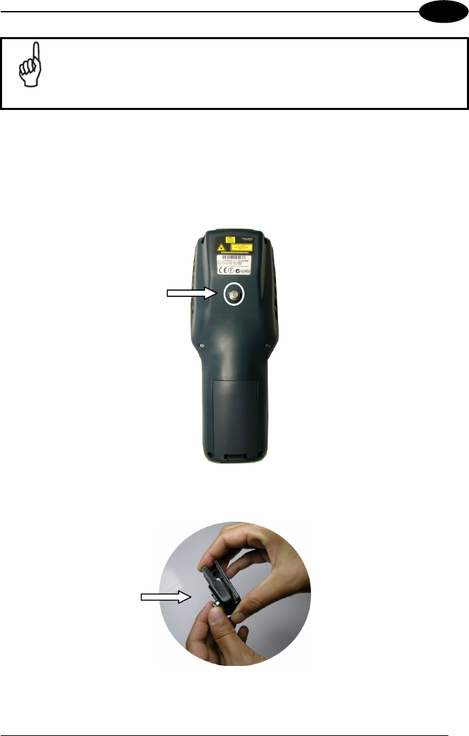
1.3.1 Using the Belt Clip
To use the belt clip, proceed as follows:
1. Remove the elastic strap and unscrew the strap pivot.
2. Release the belt clip pivot by pressing the belt clip unlock button.
KYMAN-NET™
4
1
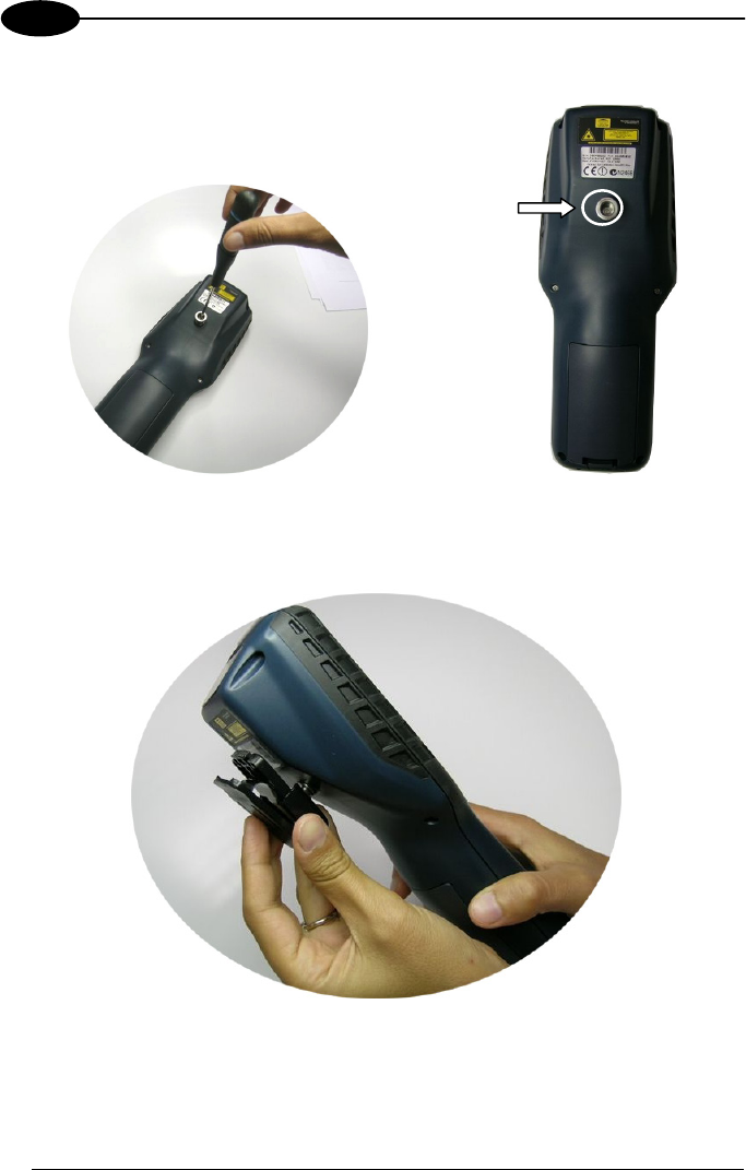
3. Screw the belt clip pivot on the terminal by using the fixing screw.
4. Insert the terminal in the belt clip by sliding the belt clip pivot into the belt clip
until it clicks into place.
5. To release the terminal, press the belt clip unlock button.

INTRODUCTION
5
1
1.4 ACCESSORIES
Cradles
94A151101 Kyman-NET™ Single Cradle Desk (includes slot for spare battery
pack recharge; RS232 and USB communications)
94A151107 Kyman-NET™ Vehicle Cradle
Charger
94A151102 Kyman-NET™ Multi-Battery Pack Charger (4 slots)
Batteries
94ACC1302 Kyman-NET™ Standard Battery Pack (Li-Ion battery pack 2200
mAh@7.4 V)
Power Supply
94ACC4595 FPS18 Power Supply without cord for Kyman-NET™ Single Cradle
Desk, for Kyman-NET™ Multi-Battery Charger and for WIN-NET Serial/USB
PWR Cables
94ACC1150 Power cord EU 3-pin
Cables
94A051008 WIN-NET SERIAL CABLE (HRS 3500-16P-CV) cable for RS232
direct connection between the mobile computer and the PC
94A051009 WIN-NET USB CABLE (HRS 3500-16P-CV) cable for USB direct
connection between the mobile computer and the PC
94A051014 WIN-NET SERIAL PWR CABLE (HRS 3500-16P-CV) cable for
RS232 and power connections
94A051015 WIN-NET USB PWR CABLE (HRS 3500-16P-CV) cable for USB
and power connections
94A051012 WIN-NET VEHICLE PWR CAB (HRS 3500-16P-CV) cable for
car/truck cigarette lighter power adapter
Various
94ACC1304 Kyman-NET™ Belt Holster
94ACC1303 Kyman-NET™ Functional Case
94ACC1301 Stylus Pen (20 pcs)
94ACC1300 JET™ & Kyman-NET™ Backstrap Kit (1+1 pcs)
KYMAN-NET™
6
2
2 CONNECTIONS
2.1 CONNECTION TO THE HOST COMPUTER
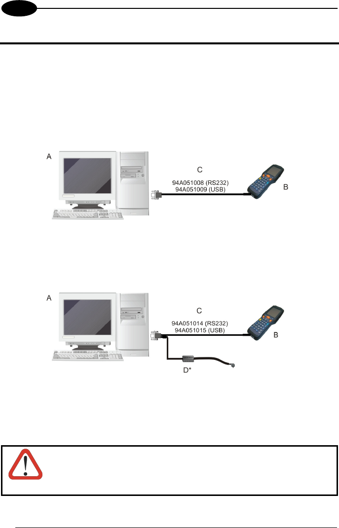
2.1.1 RS232/USB Direct Connection
You can use a cable to connect the Kyman-NET™ to a host computer to transfer
data.
Key:
A Host computer C RS232 cable or USB cable
B Kyman-NET™
Key:
A Host computer C RS232 cable or USB cable
B Kyman-NET™ D Power Supply*
* Recommended Power Supply: FPS18 AC/DC Power Supply (94ACC4595).
CAUTION
USB communication may not be completely guaranteed while
batteries are simultaneously in charge. Avoid the power supply
connection when the USB link is active.
CONNECTIONS
7
2
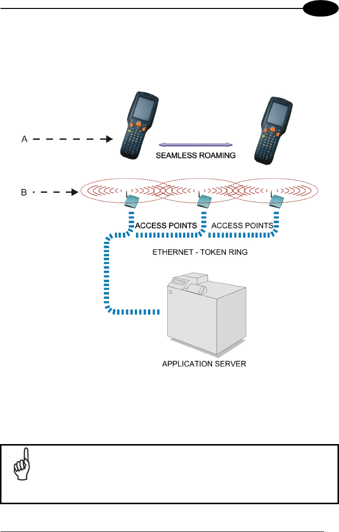
2.1.2 WLAN Connection
Kyman-NET™ Wi-Fi models can communicate with the host using the on-board radio
frequency module and an Access Point connected to the host computer.
Key:
A) Kyman-NET™
B) Access point
NOTE
In order to avoid wasting power, the Wi-Fi module is off by default. If
you need to have the Wi-Fi module working, the module must be
powered on using the Wireless Communications applet (see par.
3.7.4). To start configuring your WLAN connection, tap the Wi-Fi icon
at the bottom of the screen.
KYMAN-NET™
8
2
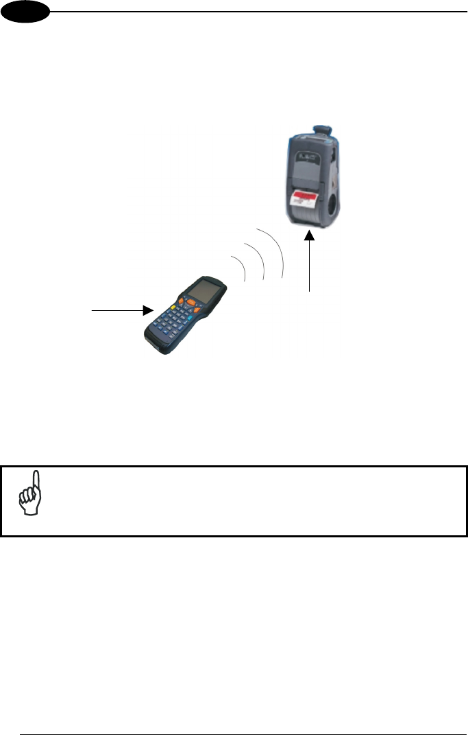
2.1.3 WPAN Connections
Kyman-NET™ mobile computers can communicate with a Bluetooth® device, such as
a printer, within a range of 10 m, using the on-board Bluetooth® module.
Key:
A) Kyman-NET™
B) Bluetooth® printer
NOTE
In order to avoid wasting power, the Bluetooth® module is off by
default. If you need to have Bluetooth® working, the module must be
powered on using the Wireless Communications applet (see par.
3.7.4), and perform the Discovery procedure (see par. 3.8.2).
B
A
CONNECTIONS
9
2
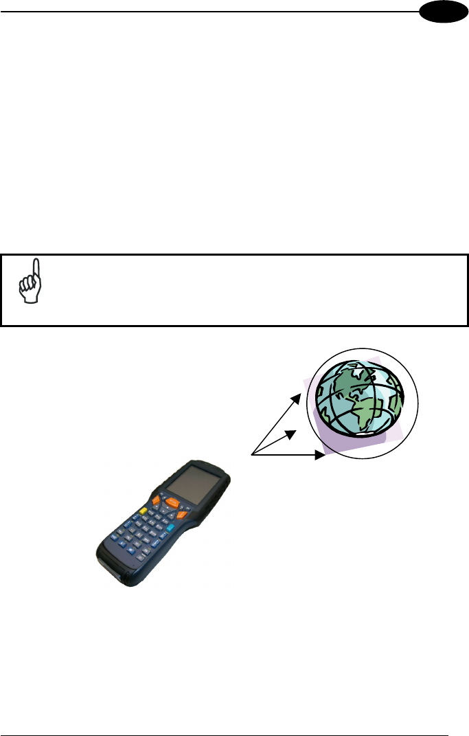
2.1.4 WWAN Connections
Kyman-NET™ GSM/GPRS models enhance your connectivity solutions giving you
an opening to an international wireless infrastructure that is the standard in Europe
and Asia.
GSM (Global System for Mobile communications), is a digital mobile phone system
based on TDMA; it utilizes the 900, 1800 and 1900 MHz bands.
GPRS supports IP (Internet Protocol) and allows accessing Internet and Intranet
services, such as sending and receiving e-mail or Web browsing.
In order to use a WWAN Connection you have to install a SIM Card (see instructions
on the following page).
NOTE
In order to avoid wasting power, the GSM/GPRS module is off by
default. If you need to have GSM/GPRS working, the module must
be powered on using the Wireless Communications applet (see par.
3.7.4.)
KYMAN-NET™
10
2
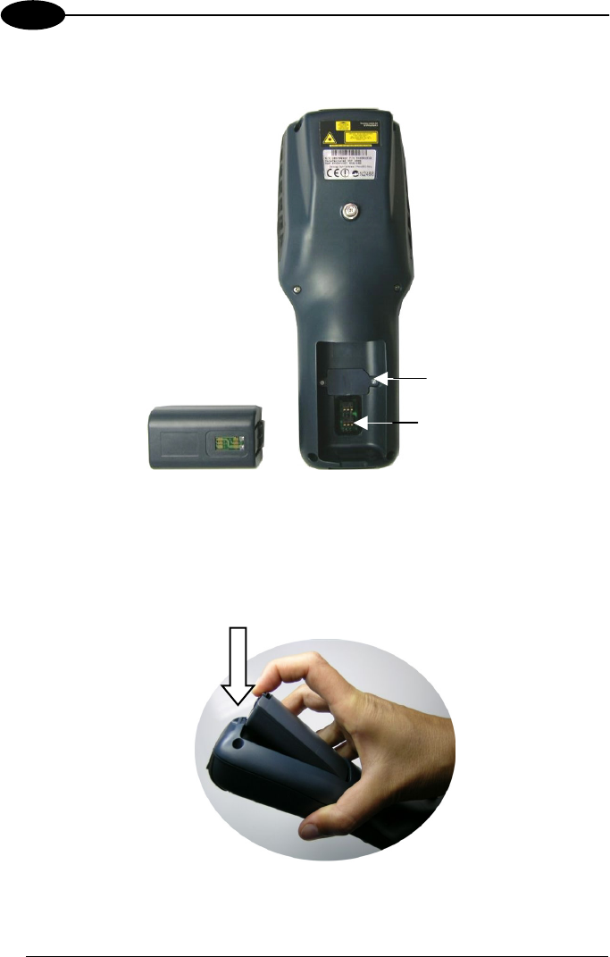
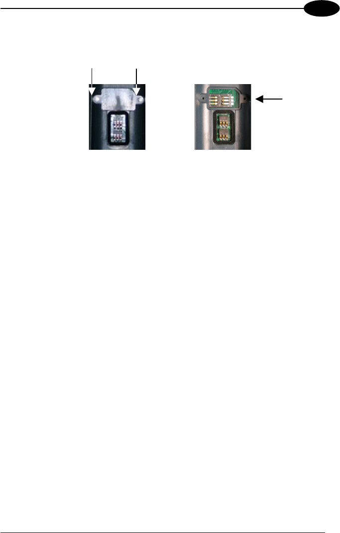
Installing the SIM Card
To correctly insert the SIM Card, proceed as follows:
1- Turn off the Kyman-NET™ mobile computer.
2- Pull the battery latch down as indicated in the figure below and remove the
battery pack.
SIM Protection Cover
Battery Contacts
CONNECTIONS
11
2
3- Open the Sim Card slot by unscrewing the two protection cover screws (A, B).
4- Position the SIM Card with its contacts downwards, place the protection cover
on the slot and close it with the two fixing screws.
Removing the SIM Card
To remove the SIM card, follow the steps above to access the SIM area, and remove
it from its slot.
SIM Card
Slot
A B
KYMAN-NET™
12
2
2.2 CONNECTION CABLES
The following cables are listed with their order number.
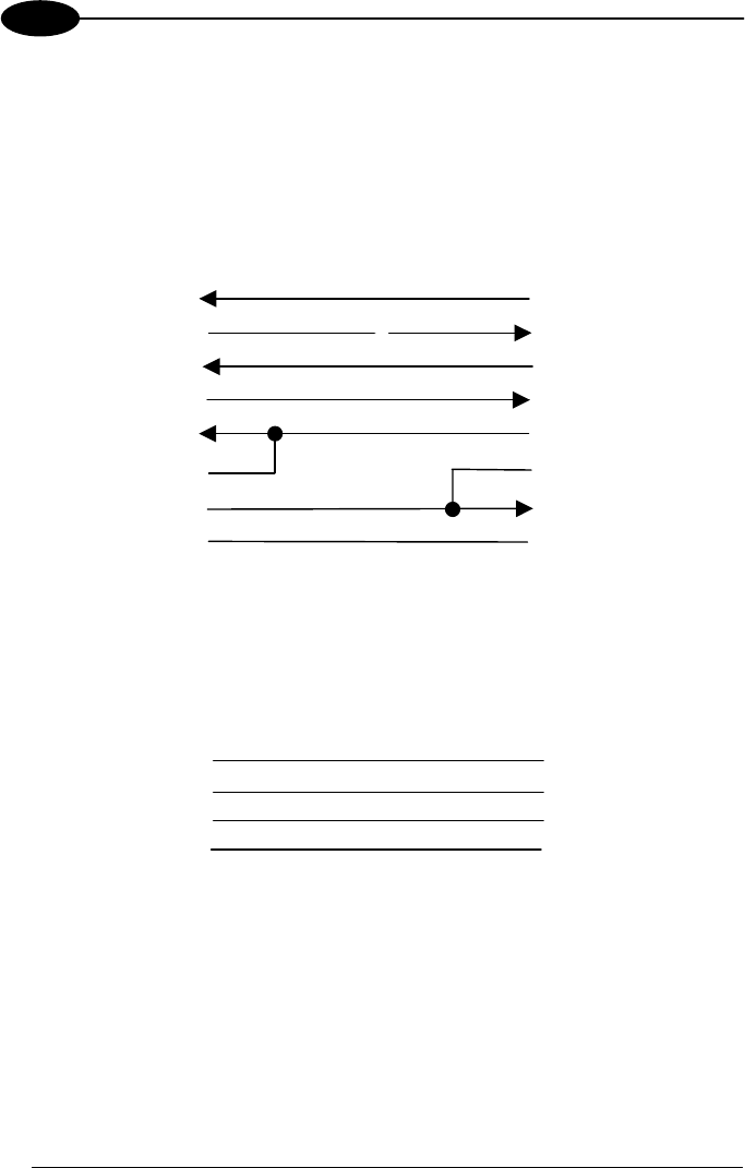
RS232 Direct Connection:
94A051008 WIN-NET SERIAL CABLE (HRS 3500-16P-CV)
RX
TX
5
10
13
3
6 2
RTS
11
DSR
5
8
DTR
GND
9 4
Kyman-NET™ side
16-
p
in
7
1
6
CTS
8
HOST/PC side
9-pin (female)
7
USB Direct Connection:
94A051009 WIN-NET USB CABLE (HRS 3500-16P-CV)
Kyman-NET™ side
16-pin HOST/PC side
9-pin (female)
4
1
D- 3
2
D+
V+
GND
15
16
13
14
CONNECTIONS
13
2
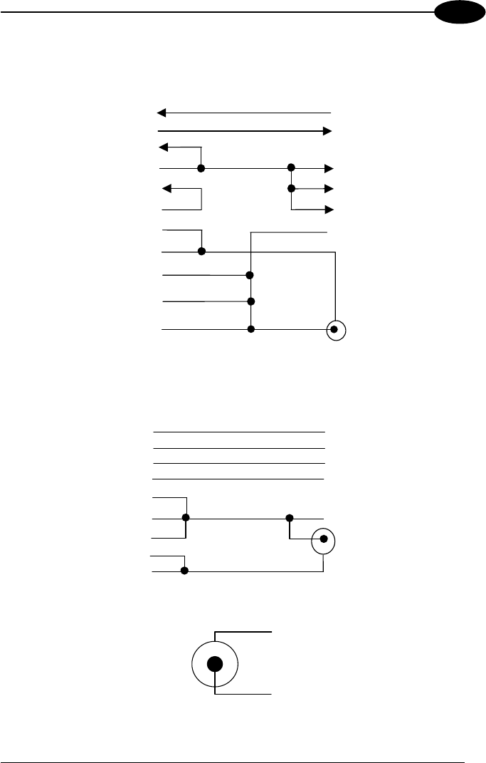
RS232 Direct Connection:
94A051014 WIN-NET SERIAL PWR CABLE (HRS 3500-16P-CV)
RX
TX
3
6 2
5
1
CTS
Kyman-NET™ side
16-pin HOST/PC side
9-pin (female)
6
8
7
8
9
10
5
1
2
3
4
13
TX
RX
RTS CD
DSR DSR
DTR CTS
GND
VALIM
GND
GND
GND POWER
CONNECTOR
USB Direct Connection:
94A051015 WIN-NET USB PWR CABLE (HRS 3500-16P-CV)
HOUSING
1
D(+) 2
3
D(-)
V+
SHIELD
16
15
HOUSING
14
4
13
3
2
1
4
POWER
GND
VALIM
Power Supply Polarity:
GND
VEXT
KYMAN-NET™
14
3
3 USE AND FUNCTIONING
The use of the Kyman-NET™ depends on the application software loaded. However
there are several parameters that can be set and utilities that can be used to perform
some basic functions such as data capture, communications, file management, etc.
3.1 STARTUP
The Kyman-NET™ turns on when the battery pack or the external supply is inserted.
After the battery pack is installed, use the [ON/OFF] key to turn the mobile computer
on and off.
As soon as the mobile computer is on, the Windows CE .NET desktop configuration
will appear on the screen. Wait a few seconds before starting any activity so that the
mobile computer completes its startup procedure.
Use the stylus as suggested in paragraph 3.2 to select icons and options.

USE AND FUNCTIONING
15
3
The mobile computer goes into power-off (low power with display and keyboard
backlight off), when it is no longer used for more than a programmable timeout, which
is defined in the POWER applet of the Control Panel. In this mode it can be
awakened (resuming operation) by the [ON/OFF] key.
NOTE
The mobile computer can also be awakened or turned off by the
application program.
3.2 USING THE STYLUS
The stylus selects items and enters information. The stylus functions like a mouse.
Tap: Touch the screen once with the stylus to open items and select
options.
Drag: Hold the stylus on the screen and drag across the screen to
select text and images. Drag in a list to select multiple items.
Tap-and-hold:
Tap and hold the stylus on an item to see a list of actions
available for that item. On the pop-up menu that appears, tap the
action you want to perform.
The stylus is factory aligned; however, it is possible to align the cursor on the screen
with the tip of the stylus. Enter the STYLUS applet of the Control Panel and tap the
center of each target that appears on the screen with the tip of the stylus.
KYMAN-NET™
16
3
3.3 DATA CAPTURE
To configure and enable data capture parameters refer to par. 3.6.
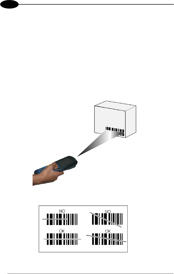
3.3.1 Laser Data Capture
To scan barcodes, point the Kyman-NET™ laser model onto the code from a
distance within the reading range while pressing the SCAN key. See the reading
diagrams in par. 5.2 for the reading range of your model.
The lighted band emitted by the laser must completely intercept the barcode as
shown in the figure below. If enabled, the emission of an acoustic signal will indicate
that the scan has taken place correctly.
USE AND FUNCTIONING
17
3
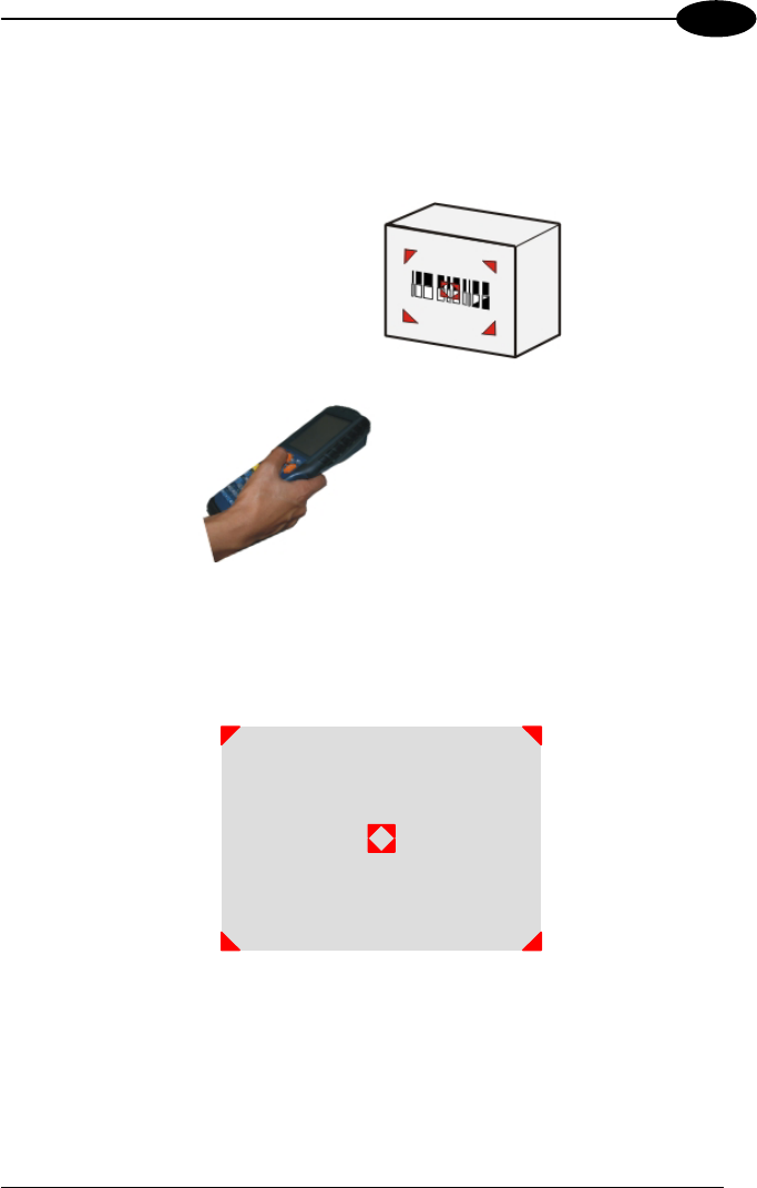
3.3.2 Imager Data Capture
To read a 1D or 2D code, simply point the Kyman-NET™ Imager model onto the
code from a distance within the reading range (See par. 5.1, section Kyman-NET™
Imager Optical Features) and press the SCAN key.
The Kyman-NET™ Imager uses an intelligent aiming system pattern similar to those
on cameras, which indicates the field of view which should be positioned over the
code:
Aiming System
If the aiming system pattern is centered over the entire symbology as shown in the
following figure, either wait for the timeout or release the Scan key to capture the
image.
KYMAN-NET™
18
3
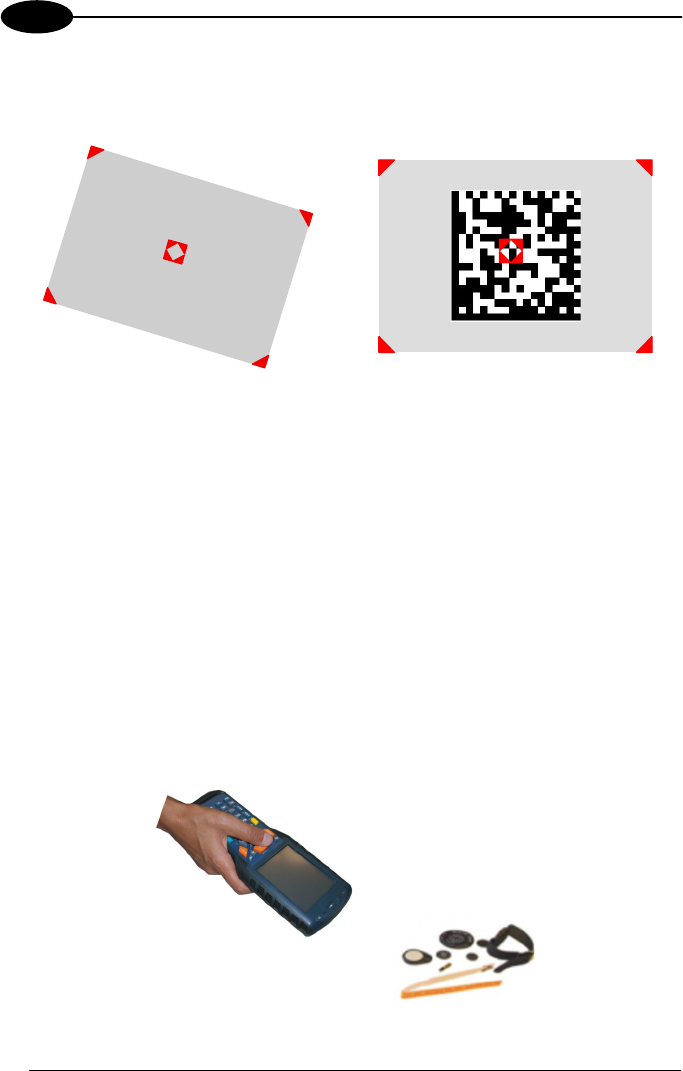
A red beam illuminates the code, which is captured and decoded. You will get a good
read.
Linear barcode 2D Matrix symbol
ÌBX3ÉÎ
Relative Size and Location of Aiming System Pattern
The field of view changes its size as you move the reader closer or farther away from
the code. The field of view indicated by the aiming system pattern will be smaller
when the Kyman-NET™ Imager is closer to the code and larger when it is farther
from the code.
Symbologies with smaller bars or elements (mil size) should be read closer to the
unit. Symbologies with larger bars or elements (mil size) should be read farther from
the unit. (See par. 5.1 for further details).
3.3.3 RFID Data Capture
To read or write a tag, place the Kyman-NET™ so that the RFID emission window is
in front of and almost in contact with the tag, then press the SCAN key or the
application defined key.
USE AND FUNCTIONING
19
3
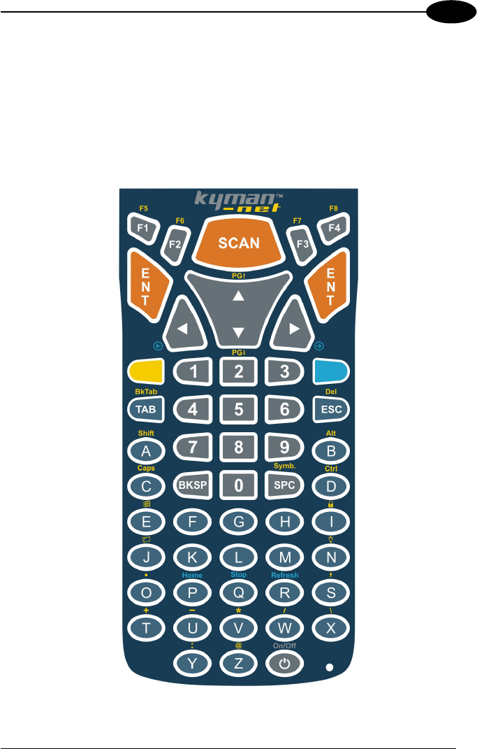
3.4 DESCRIPTION OF THE KEYS
The Kyman-NET™ provides two different keyboards, an alphanumeric keyboard and
a numeric keyboard, having a total of respectively 53 and 36 keys.
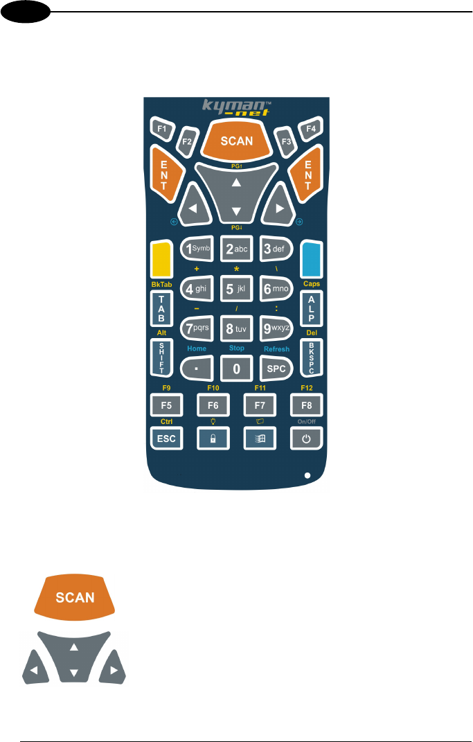
3.4.1 Alphanumeric Keyboard (53-key Model)
The following image shows the Alhanumeric keyboard.
KYMAN-NET™
20
3
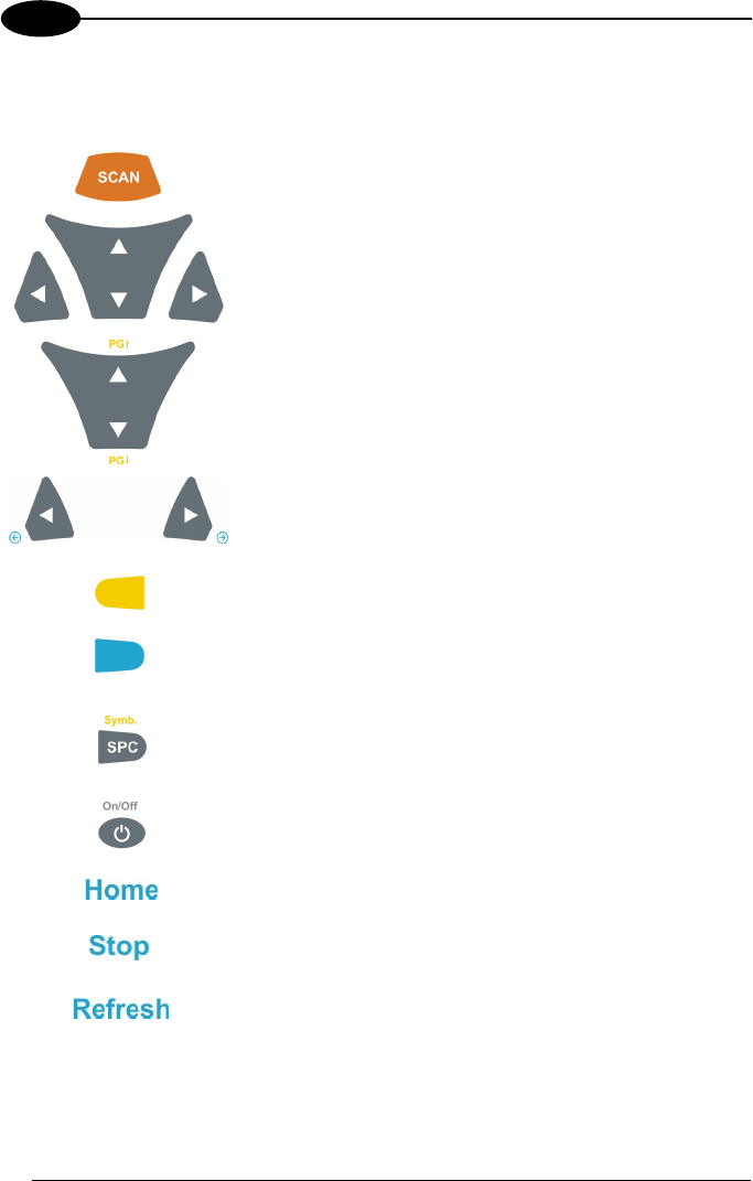
Main Keys Function
KEY FUNCTION
It starts data capture.
They let you move forwards, backwards, upwards or
downwards within text fields, scroll through a Menu list or
browse among folder files.
After a yellow modifier key press, they let you scroll the
pages up and down.
After a blue modifier key press, the blue arrows allow
moving forwards or backwards within the Internet
Explorer browser pages.
Yellow modifier: when pressed before a standard key, it
enables the function printed in yellow above the key.
Blue modifier: when pressed before a standard key, it
enables the function printed in blue above the key.
After a yellow modifier key press, subsequent key
presses allow the selection of seldom used characters.
The selected character is entered after a short timeout
or if a different key is pressed.
It powers the Kyman-NET ON or OFF.
After a blue modifier key press, it allows returning to the
Home page.
After a blue modifier key press, it allows ending a page
downloading.
After a blue modifier key press, it performs a page
refresh.
USE AND FUNCTIONING
21
3
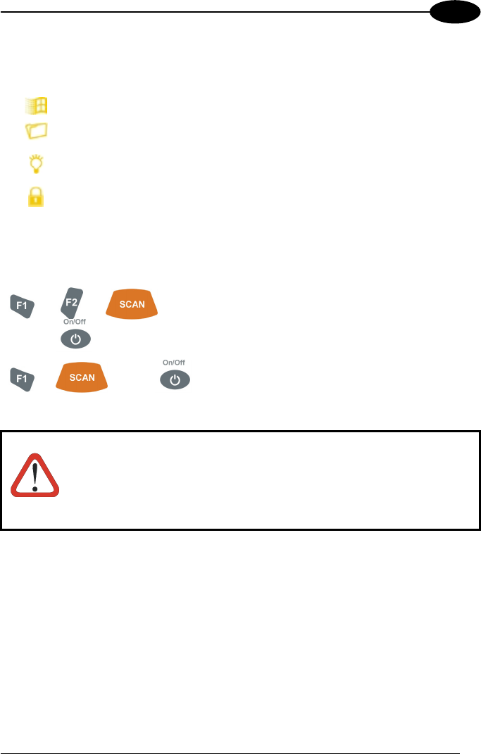
Special Function Icons
ICON FUNCTION
After a yellow modifier key press, it opens the Start menu.
After a yellow modifier key press, it opens the file manager.
After a yellow modifier key press, it switches ON/OFF the keyboard
backlight.
After a yellow modifier key press, it locks and unlocks the keyboard.
Hardware and Software Reset
By pressing these keys simultaneously, a
system hardware reset is performed.
By pressing these keys simultaneously, a
system software reset is performed.
CAUTION
Before performing a hardware or software reset, it is recommended
to:
- execute a system backup to keep persistent your more
important files and applications. See par. 3.9;
- save the registry to non-volatile memory to guarantee the
persistence of the Windows configuration. See par. 3.7.2.
KYMAN-NET™
22
3
3.4.2 Numeric Keyboard (36-key Model)
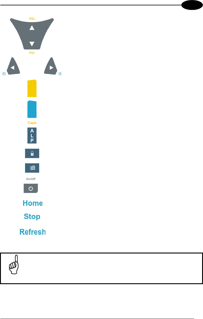
Main Keys Function
KEY FUNCTION
It starts data capture.
They let you move forwards, backwards, upwards or
downwards within text fields, scroll through a Menu list or
browse among folder files.
USE AND FUNCTIONING
23
3
After a yellow modifier key press, they let you scroll the
pages up and down.
After a blue modifier key press, the blue arrows allow
moving forwards or backwards within the Internet
Explorer browser pages.
Yellow modifier: when pressed before a standard key, it
enables the function printed in yellow above the key.
Blue modifier: when pressed before a standard key, it
enables the function printed in blue above the key.
When pressed, it toggles the alphanumeric/numeric
modes.
It locks and unlocks the keyboard.
It opens the Start menu.
It powers the Kyman-NET™ ON or OFF.
After a blue modifier key press, it allows returning to the
Home page.
After a blue modifier key press, it allows ending a page
downloading.
After a blue modifier key press, it performs a page
refresh.
NOTE
Once the Alpha mode has been entered, press the Alpha key again
to exit this mode.
KYMAN-NET™
24
3
Keys from 1 to 9 share the following behavior scheme:
A. Function of the key when directly pressed
B. Function of the key when in Alpha mode.
When in Alpha mode press the key until the desired letter is shown.
The letter is entered if you wait for a short timeout or if you press a different
key.
Special Function Icons
ICON FUNCTION
It opens the file manager.
It switches ON/OFF the keyboard backlight.
Hardware and Software Reset
By pressing these keys simultaneously, a system
hardware reset is performed.
By pressing these keys simultaneously, a system
software reset is performed.
CAUTION
Before performing a hardware or software reset, it is recommended
to:
- execute a system backup to keep persistent your more
important files and applications. See par. 3.9;
- save the registry to non-volatile memory to guarantee the
persistence of the Windows configuration. See par. 3.7.2.
A
C

USE AND FUNCTIONING
25
3
3.5 STATUS INDICATORS
3.5.1 LED Status
The Kyman-NET™ provides three different LEDs signaling the mobile computer
status.
LED STATUS
General Purpose
(left-side)
Green/Red This LED is available to the application
program.
Charging Status and
Battery Low Warning
Green constant It is constant once the charging process
has been completed.
(right side) Red blinking When the mobile computer is powered
by the battery (not by the cradle nor by
the cable), this LED blinks red to signal
that the battery is running down.
Red constant It is constant while charging.
Orange blinking It blinks when a charging error has
occurred, for example when a mobile
computer without battery is connected
to the external power or inserted into a
powered cradle.
Good Read
(middle)
Green It is constant for a configurable time to
signal that a successful read has
occurred.
KYMAN-NET™
26
3
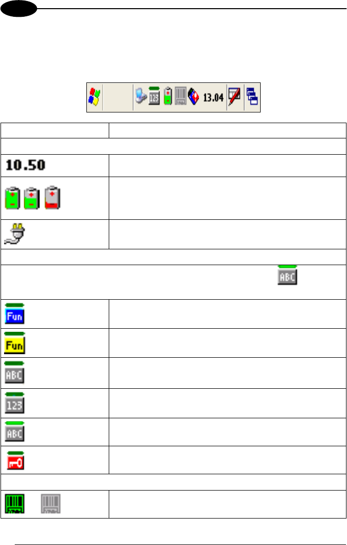
3.5.2 Status Bar
The Status Bar provides information about the time, the battery level, the keyboard
function, and the decoding status.
ICONS DESCRIPTION
Time and Battery Icons
It displays the time.
They are representative of five different icons indicating
the battery level. The icon is partially green when the
power left is >20% and partially red colored when the
power left is <20%.
It indicates that the battery is charging.
Keyboard Status Icons
The green segment over any of the following icons icon is lit when the
Capslock is active.
It indicates that the blue FUNC key has been pressed
and is going to affect the next key press.
It indicates that the yellow FUNC key has been pressed
and is going to affect the next key press.
It indicates that the keyboard is in ALPHA mode.
It indicates that the keyboard is in Normal mode.
It indicates that the keyboard is in ALPHA mode and that
the Capslock is active.
It indicates that the keyboard is locked.
Decoding Status Icons
It indicates that the decoder is active (green), not active
(grey).
USE AND FUNCTIONING
27
3
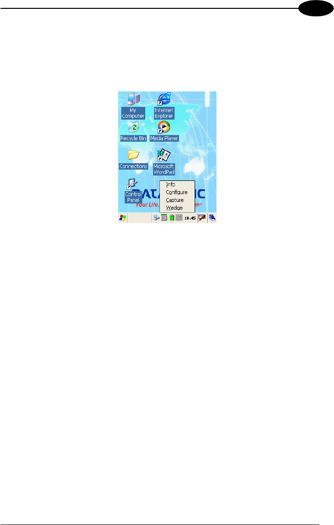
3.6 DATA CAPTURE CONFIGURATION
From the Taskbar, tap the "Data Capture" icon to open a drop–down menu. Data
Capture can also be accessed from the Control Panel.
By selecting the Info item from this drop-down menu you can access information
about the Scanner and the Software; the Configure item opens the configuration
applet (Data Capture Configuration Window), while Capture accesses the data
capture applet (Data Capture Window), which enables code reading.
The last menu item (Wedge) enables Wedge Emulation.
3.6.1 Configure
The Configuration applet contains the barcode scanning configuration parameters in
a directory tree structure. The available barcode parameters are divided into two
groups: Reader Parameters and Scan Parameters.
The Reader Parameters depend on the type of scanner module installed on the
mobile computer and allow barcode configuration (i.e. enable/disable Code 39, check
digit control, etc.).
The Scan Parameters are common to all scanner modules and allow control of the
scanning device (i.e. beeper control, LED control, laser timeout, etc.).
Each Data Capture screen window corresponds to a branch of the tree, and the
name of the current branch is displayed at the bottom of each screen window.
KYMAN-NET™
28
3
Data Capture Configuration Window
The screen format shows two columns where the left column indicates branches or
parameters. Branches have three dots in the right column (...). You can navigate
through the tree structure using the stylus or keyboard arrows directly on the item
field or from the menu.
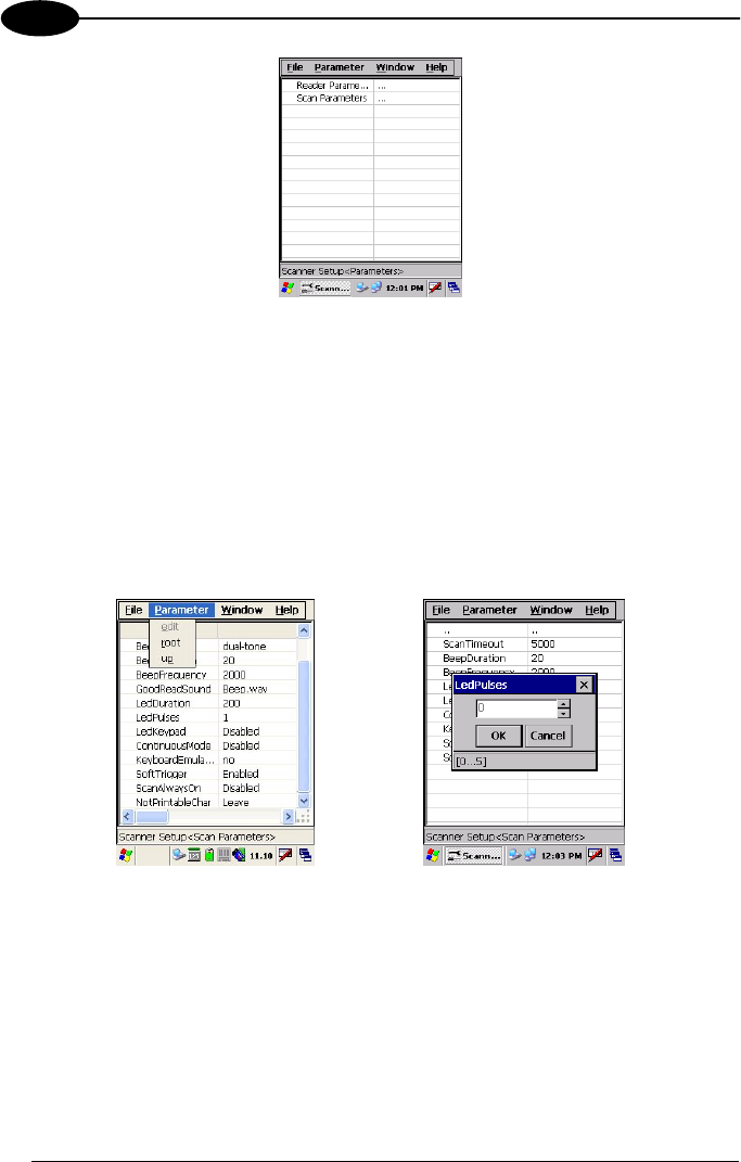
Parameters have their corresponding current values in the right column. You can edit
parameter values using the stylus or keyboard arrows directly on the item field or
from the menu. To change a value for example, select the line of the value to be
changed, choose Edit from the Parameter Menu then choose a new value from the
values listed in the box (see following figures).
Selecting Data Capture Setup Parameters
Alternatively using the stylus, you can tap once directly on the value on the right
column; continue tapping until the desired value is reached.
To activate a new configuration select the File ->Save Menu to send the new
configuration to the barcode decoding software and save the new configuration. This
will save the configuration to non-volatile memory preventing loss at the next system
reset.

USE AND FUNCTIONING
29
3
Reader Parameters
The barcode reading parameters and values are dependent upon the type of scanner
module mounted in your mobile computer. For a detailed list of parameters and of
their configuration procedures, please refer to the SDK Help file on the CD.
Scan Parameters
The Scan Parameters are common to all scanner modules and allow control of the
scanning device. The Scan parameters are described as follows:
ScanTimeout: the maximum time, in milliseconds, during which the scanner remains
on without decoding any barcode.
BeepType: if set to dual tone, the good read beep is a sequence of high and low
pitch sounds. If set to monotone, the beep is a single pitch sound.
BeepDuration: the time interval, in milliseconds, during which the beeper will sound
when the scanner reads a code. To disable the beeper, set this value to 0.
BeepFrequency: determines the frequency in Hertz of the beeper.
GoodReadSound: is the filename of a .wav file played when the scanner reads a
code.
LedDuration: the length of the good-read led pulse, in milliseconds.
LedPulses: the number of times the good-read led pulse is emitted when the
scanner reads a code.
LedKeypad: determines the keyboard backlight after each good read.
ContinuousMode: disables the effect of the ScanTimeout parameter.
KeyboardEmulation: if enabled all scanned data are transformed into keyboard
events and can therefore be displayed and saved to a file as if input from the PDA
keyboard. If set to “Yes (Clipboard)”, it copies the scanned data to the system
clipboard.
SoftTrigger: when enabled, the laser can be turned on/off by the application
software.
ScanAlwaysOn: enables the scanner for barcode reading independently from the
application software. If set to “Disabled after read”, it disables the reading after a
reading attempt. In case the scan button is accidentally pressed, this selection
prevents the driver from decoding new data while the application is still elaborating
previous data.
NotPrintableChar: if set to “Remove”, all not printable characters included in the
scanned data are deleted and the final barcode will include only printable characters.
KYMAN-NET™
30
3
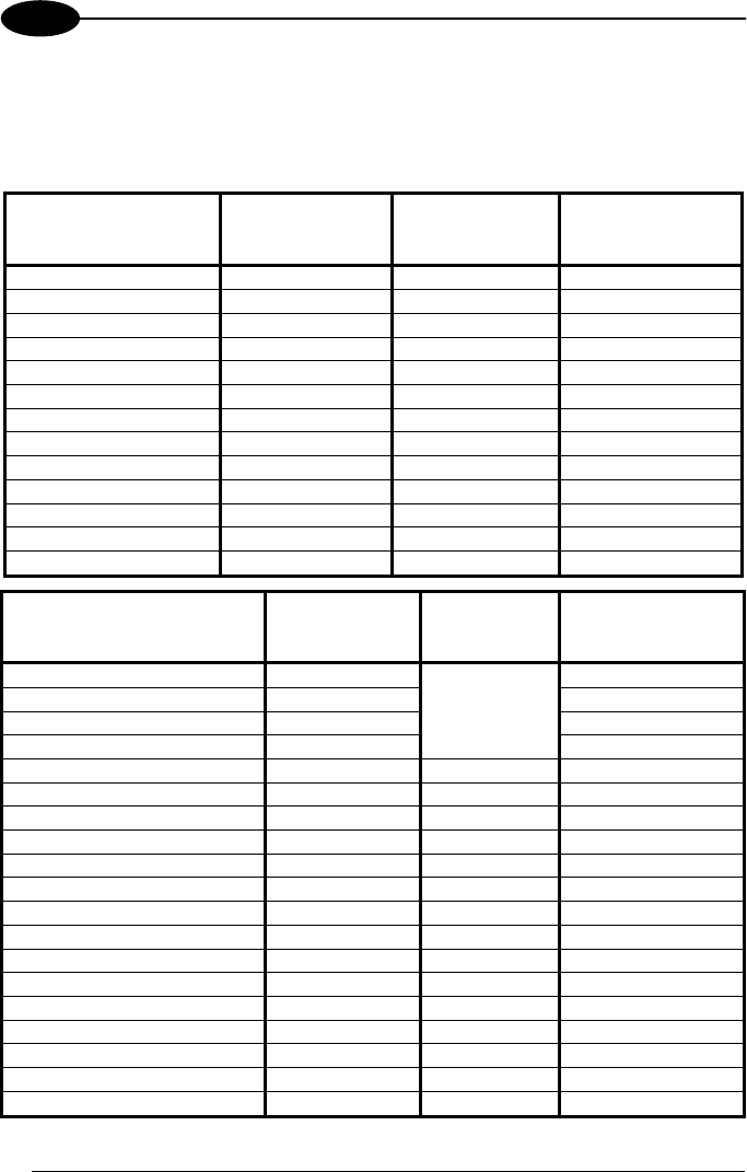
Default Settings
The following tables contain the default values for the major barcode setup
parameters, according to the type of scan engine mounted on the mobile computer.
For a complete list of parameters and of their configuration procedures, please refer
to the SDK Help file on the CD.
SCAN PARAMETERS
Laser Models
(XXX-1XX,
XXX-4XX)
Imager Models
(XXX-7XX)
Laser Extra Long
Range Models
(XXX-6XX)
ScanTimeout 5000 Not available 5000
BeepType Dual tone Dual tone Dual tone
BeepDuration 20 20 20
BeepFrequency 2000 2000 2000
GoodReadSound Beep.wav Beep.wav Beep.wav
LedDuration 200 mS 200 mS 200 mS
LedPulses 1 1 1
LedKeypad Disabled Disabled Disabled
ContinuousMode Disabled Disabled Disabled
KeyboardEmulation Disabled Disabled Disabled
SoftTrigger Enabled Enabled Enabled
ScanAlwaysOn Disabled Disabled Disabled
NotPrintableChar Leave Leave Leave
BARCODE SYMBOLOGY
SPECIFIC READER
PARAMETERS
Laser Models
(XXX-1XX,
XXX-4XX)
Imager
Models
(XXX-7XX)
Laser Extra Long
Range Models
(XXX-6XX)
UPC A Enabled Enabled
UPC E Enabled Enabled
EAN 8 Enabled Enabled
EAN 13 Enabled
*
Enabled
UPC E1 Disabled
EAN Bookland Disabled
UPC/EAN/JAN Enabled
Code 39 Enabled Enabled Enabled
Code 39 Full ASCII Disabled Disabled Disabled
Code 32 Disabled Disabled
Code 39 Trioptic Disabled
2/5: Interleaved Enabled Enabled Enabled
2/5: Industrial Disabled Disabled
2/5: Matrix Disabled
Code 128 Enabled Enabled Enabled
EAN 128 Enabled Disabled Enabled
ISBT 128 Disabled
Codabar Enabled Enabled Disabled
RSS Disabled
USE AND FUNCTIONING
31
3
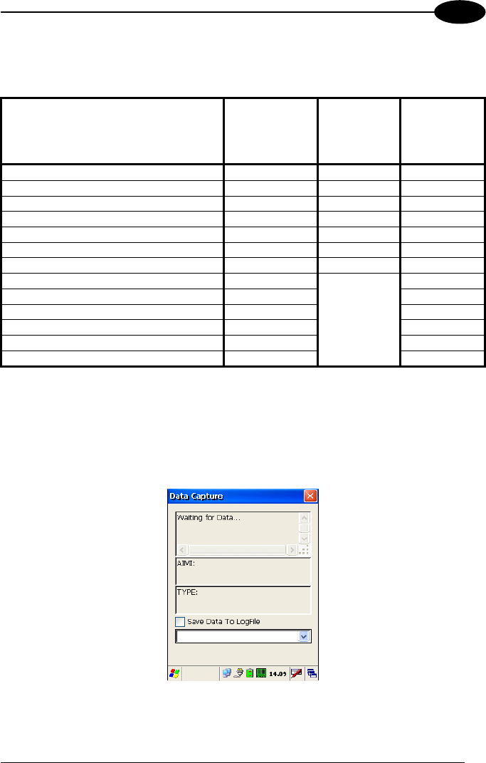
* In the Imager models these codes may only be enabled or disabled as a group by
the UPC/EAN/JAN family selection (see a few lines below in the same table).
BARCODE SYMBOLOGY
SPECIFIC READER PARAMETERS
Laser Models
(XXX-1XX,
XXX-4XX)
Imager
Models
(XXX-7XX)
Laser Extra
Long Range
Models
(XXX-6XX)
MSI Enabled Disabled
Plessey Disabled
Code 93 Disabled Enabled Disabled
Code 11 Disabled
PDF - 417 Enabled
Data Matrix Enabled
QR Enabled
POSTNET
PLANET
Japan Post
Australia Post
KIX Code
Royal Mail Code (RM4SCC)
Disabled*
* These codes may be enabled individually but are disabled as a group.
3.6.2 Capture
The Data Capture applet (Capture) enables code reading.
Data Capture Window
KYMAN-NET™
32
3
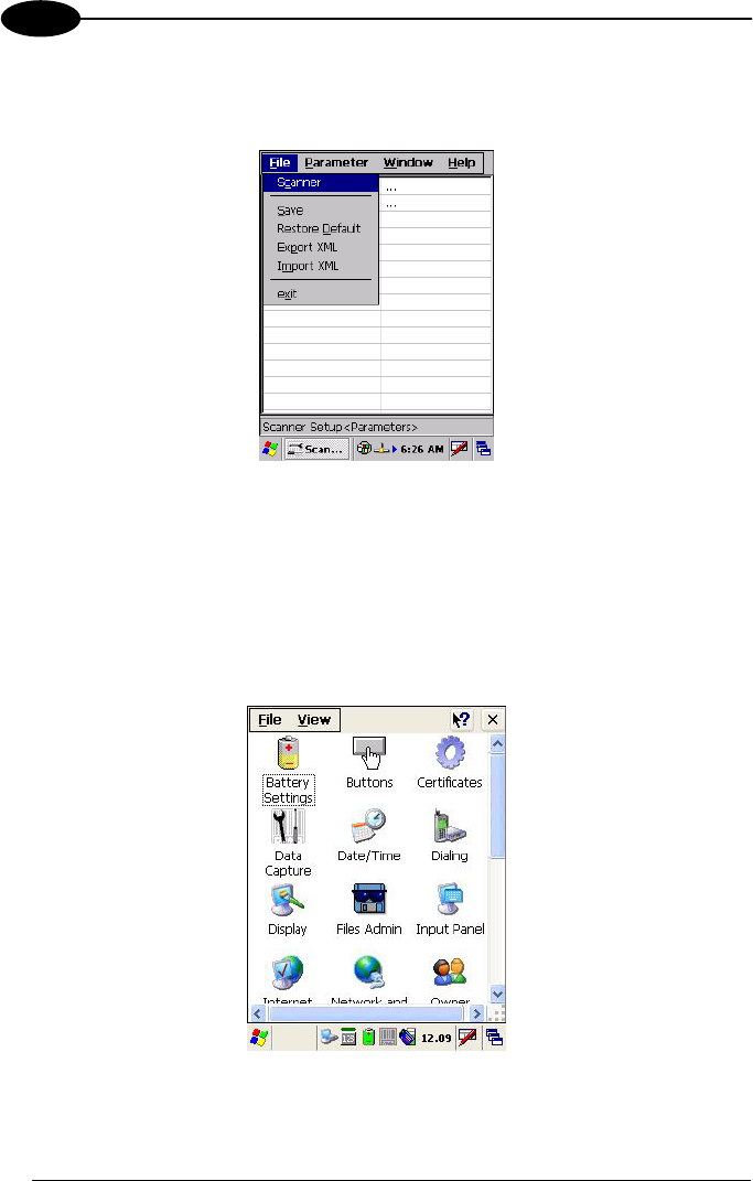
Data Capture can also be enabled through the Configuration applet by selecting File
->Scanner from the main menu, or by enabling the parameter Scan Always On in the
Scan Parameters branch.
Enabling the Data Capture
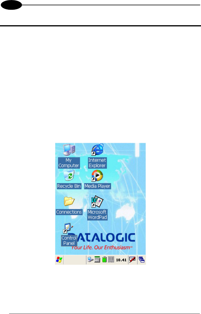
3.7 CONTROL PANEL
From the Desktop, double tap on the "Control Panel" icon to open the Windows CE
.NET control panel main window. The Control Panel can also be launched from Start
->Settings ->Control Panel.
APPLET programs are displayed as icons; one icon corresponds to each APPLET.
Control Panel
USE AND FUNCTIONING
33
3
3.7.1 Buttons
The BUTTONS Applet allows assigning desired applications to be launched by the
Act button or one of the function keys (F1, F2, F3, F4).
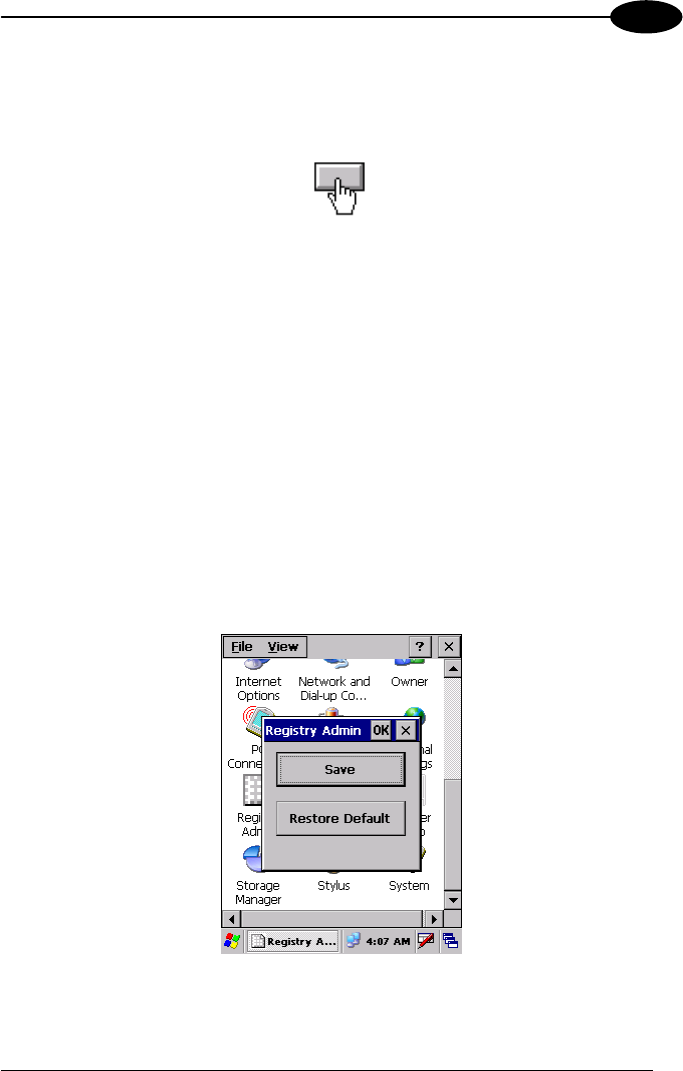
3.7.2 Registry
The REGISTRY ADMIN applet provides management of Windows CE .NET registry.
Select the REGISTRY ADMIN applet by double tapping the Registry Admin icon.
The Registry Administration Main window appears. Two functions are available:
- Save Registry allows permanently saving the Windows configuration (example:
custom configuration of screen desktop background color, or network adapter
configuration) to non-volatile memory (SAVE button).
- Restore Default Registry allows restoring the initial factory default configuration
(Restore Default button). After restoring the factory default configuration, you
must perform a software reset.
Saving the registry to non-volatile memory guarantees the persistence of the
Windows configuration in case of battery pack replacement.
Registry Administration Window
KYMAN-NET™
34
3
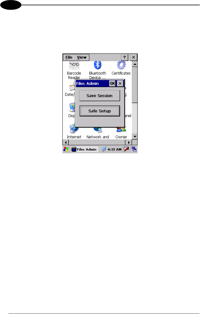
3.7.3 Files Admin
The FILES ADMIN applet enables control of the permanence of files in the System
Folder. Two functions are available on the Files Admin Main window by means of two
buttons:
Files Admin Main Window
Save Session: with this button all files will be permanently saved in the \Windows
directory in non-volatile memory. This function guarantees the steady maintenance of
every file produced during the current working session - even of sub-directories and
relevant files - with the exception of the files belonging to the FLASH image.
These current working session files will be backed-up in the \Backup\Windows
directory.
At the next hardware reset, the files previously saved in the \Backup\Windows
directory will be restored to the Windows directory (see par. 3.9).
Safe Setup: with this button, the installation of software programs will be saved to
non-volatile memory (Backup directory). Before doing this, it will be checked that the
Backup directory has enough space to save the files. If the directory space is not
enough, an error message will be shown and the program will exit the Safe Setup
function.
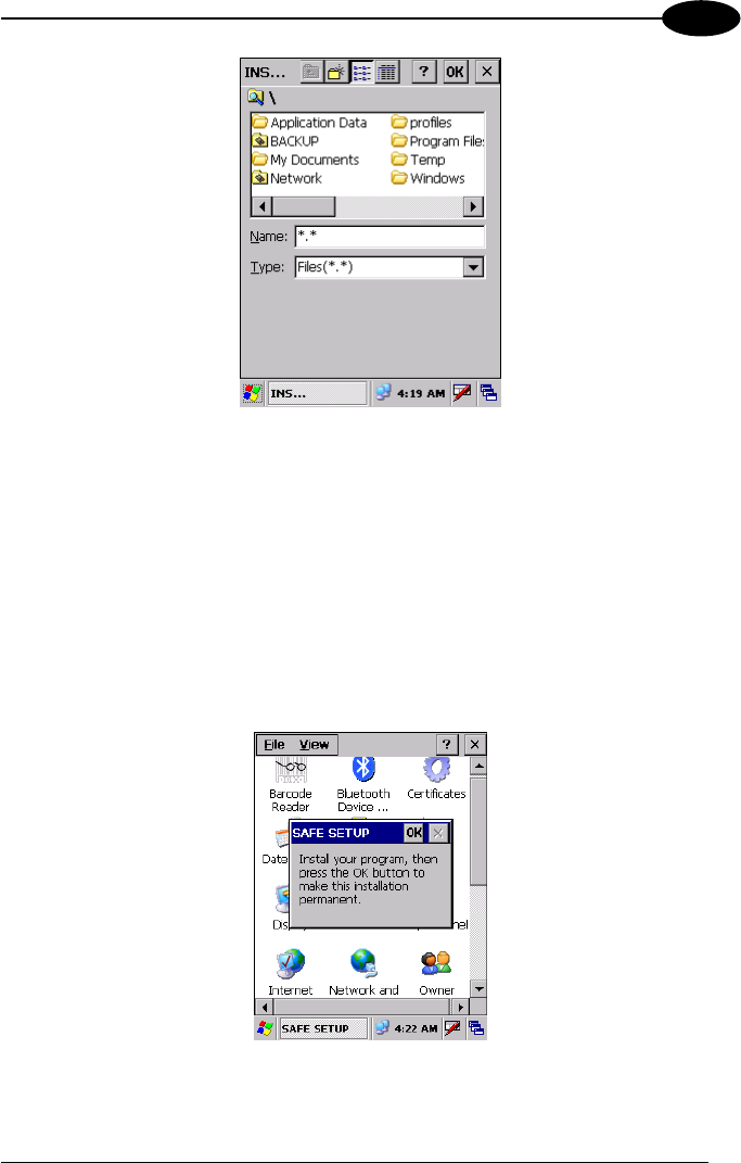
Two activating procedures are available for Safe Setup:
- Select an installation file (for example, a .CAB cabinet file) from the Safe Setup
mask.
USE AND FUNCTIONING
35
3
Safe Setup First Mask
Then select \Windows or a relevant sub-directory in the path box. Then, Safe
Setup will recognize the new files and directories present in the \Windows
directory, and will copy them to the \Backup\Windows directory. At the next
hardware reset, these files will be restored (see par. 3.9).
- Simply skip the first mask either by closing it or by pressing the ESC key. When
it closes, a new mask will pop up: it will enable any type of installation (even
remote ones like ActiveSync® installations). Make sure the installation directory
is \Windows or one of its sub-directories. After installation, tap OK: Safe Setup
will save the new files in the \Backup\Windows directory.
Safe Setup Second Mask
KYMAN-NET™
36
3
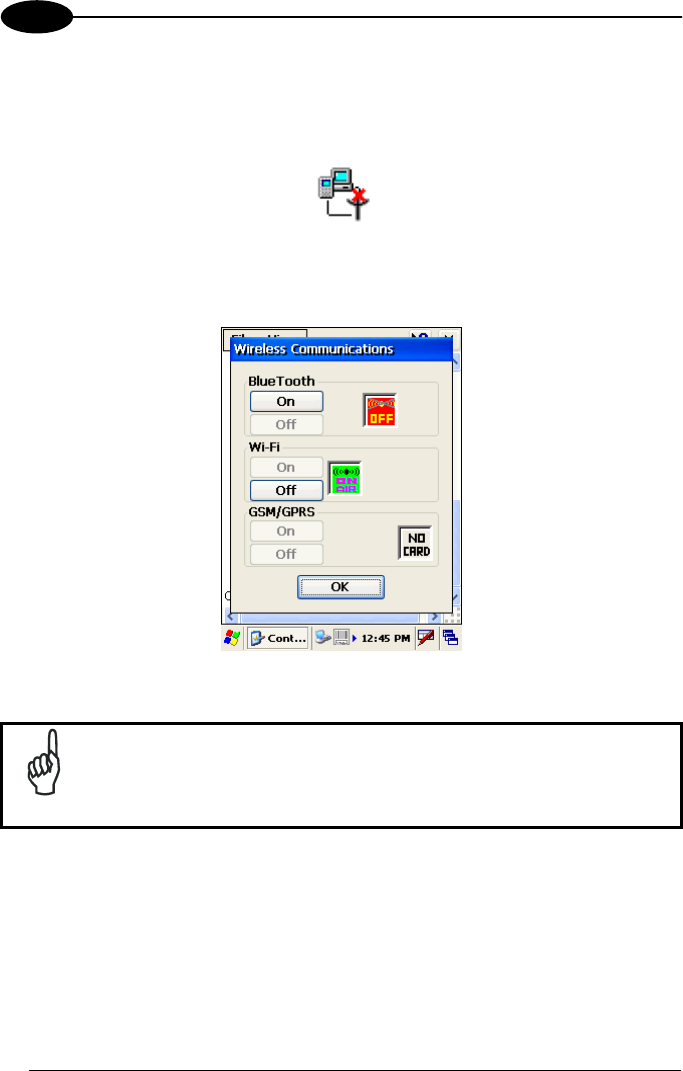
3.7.4 Wireless Communications
The WIRELESS COMMUNICATIONS applet provides management of the Wi-Fi
Card and of the Bluetooth® and GSM/GPRS modules.
Select the WIRELESS COMMUNICATIONS applet by double tapping the Wireless
Communications icon. The following window will appear:
Wireless Communications Window
NOTE
In order to avoid wasting power, all modules are off by default.
USE AND FUNCTIONING
37
3
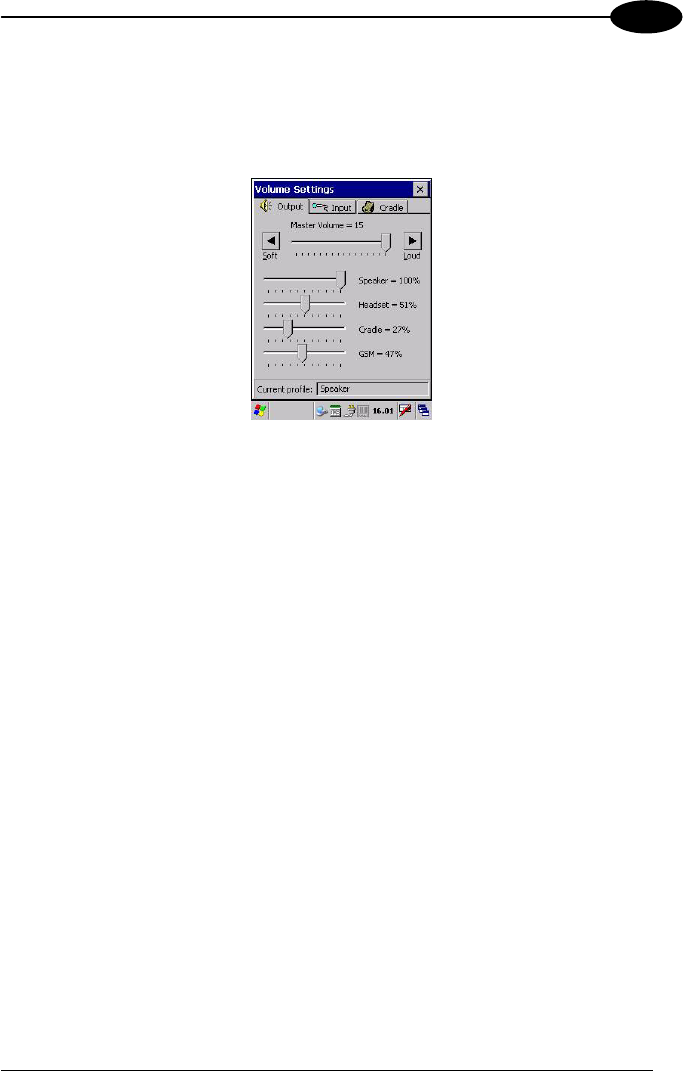
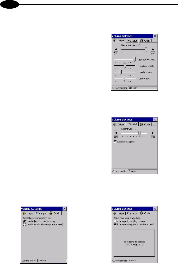
3.7.5 Volume Settings
The Volume Settings applet allows managing the audio features and appears as
follows:
Volume Settings Window
The window is divided into three tabs:
- Output tab: allows setting the volume for each audio profile;
- Input tab: allows setting the microphone recording volume;
- Cradle tab: allows selecting the cradle type and managing the vehicle cradle
headset functioning.
The Status bar always displays the current audio profile, which is activated
automatically (by the device) or manually (by the user). Available profiles are:
- Speaker: it is the typical profile reproducing audio through the mobile computer
speaker;
- Cradle: it is automatically activated as soon as the mobile computer is inserted
into the vehicle cradle. Audio is reproduced by the vehicle cradle loudspeaker.
- Headset: it is automatically activated as soon as a headset is directly connected
to the mobile computer. In case the device is inserted into the vehicle cradle and the
headset is connected to the cradle, this profile must be manually activated through
the dedicated button (refer to “Cradle Tab” paragraph). When this profile is active,
the speaker does not work;
- GSM: it is automatically activated each time a phone-call is started. It is not
available when using the cradle loudspeaker (in this case
Current Profile = Cradle).
KYMAN-NET™
38
3
Output Tab
It allows setting the volume for each audio profile:
The “Master Volume” slider allows setting
the volume used by all audio profiles. In
addition, it is possible to attenuate the
volume for each single profile through the
dedicated slider.
Input Tab
It allows setting the microphone recording volume:
The “Record Gain” slider allows setting
the recording volume, while the “Enable
Preamplifier” check box enables/disables
the preamplifier (this option is not
selectable when Current Profile = Cradle
or GSM).
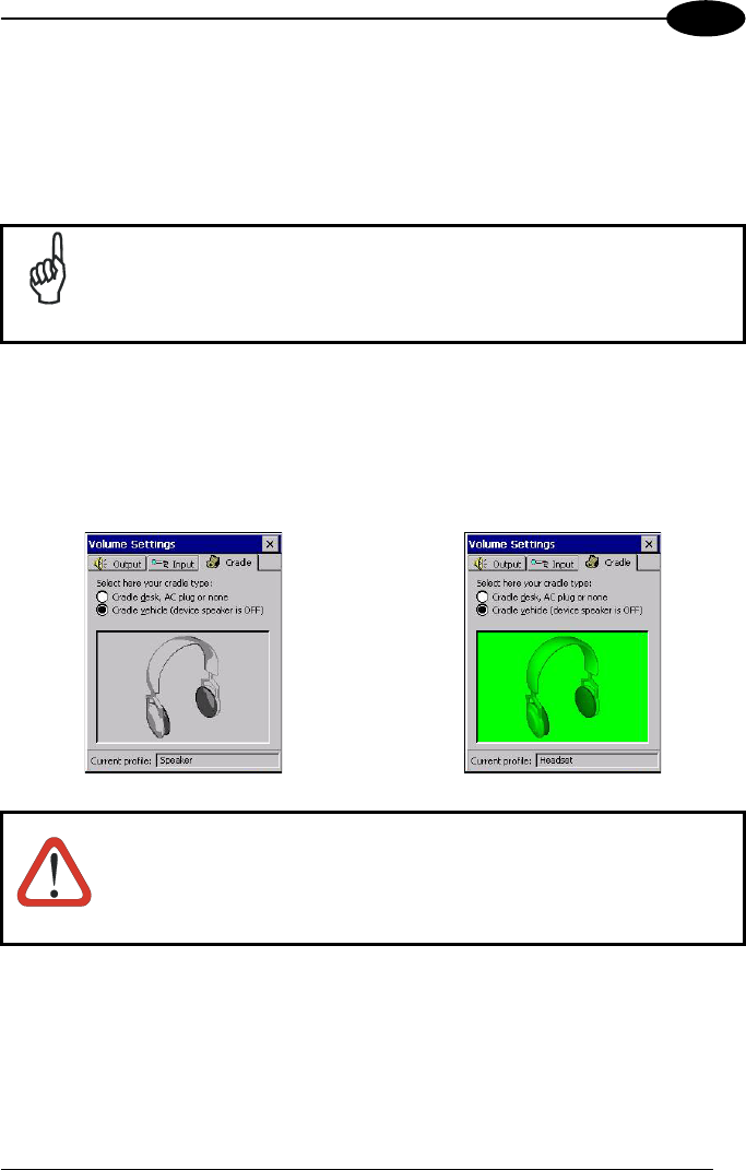
Cradle Tab
It allows selecting the cradle type and managing the vehicle cradle headset
functioning:
USE AND FUNCTIONING
39
3
Two radio buttons allow selecting the type of cradle to be used.
Check the “Cradle desk, AC plug or none” radio button, if using a cradle different
from the vehicle cradle or an AC adapter plug.
If using a vehicle cradle, check the related radio button.
NOTE
By inserting the mobile computer into the cradle when the “Cradle
vehicle” radio button is checked, the mobile computer speaker is
deactivated and audio will be reproduced through the vehicle cradle
speaker or headset.
By selecting the “Cradle Vehicle” check box, a further button will appear allowing to
enable the headset profile when using the vehicle cradle. If pressed, the button
displays the headset icon in gray until the device is inserted into the vehicle cradle.
Once inserted, the headset icon turns to green and the device activates the headset
profile (refer to the following figures). Actually, the headset is ready to reproduce
audio as soon as it is connected to the cradle jack:
WARNING
Do not use the vehicle cradle headset if the headset button is
disabled, since it may cause hearing damage.
KYMAN-NET™
40
3
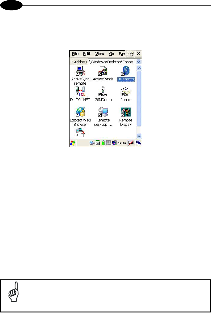
3.8 WINDOWS CONNECTIONS
From the Desktop, double tap on the "Connections" folder to open the following
window:
Windows Connections
3.8.1 Microsoft® ActiveSync®
Microsoft® ActiveSync® gives you the possibility to connect your desktop computer to
your Kyman-NET™ and synchronize the information on them. Synchronization
compares the data on the Kyman-NET™ with that on the desktop computer and
updates both computers with the most recent information.
With ActiveSync®, it is possible to:
- Back up and restore Kyman-NET™ data.
- Copy files between Kyman-NET™ and desktop computer.
- Synchronize files by selecting a synchronization mode.
It is possible to constantly synchronize while connected to a desktop computer or,
alternatively, synchronization can be performed only when the synchronize command
is chosen. You can select which information types are synchronized and control how
much data is synchronized.
NOTE
By default, ActiveSync® does not automatically synchronize all types
of information. Use ActiveSync® options to turn synchronization on
and off for specific information types.

USE AND FUNCTIONING
41
3
For example:
Synchronize Microsoft Word and Microsoft Excel files between the Kyman-NET™
and the desktop computer. The files will automatically be converted to the correct
format.
You can establish a connection by Serial cable, by USB cable or by network.
Moreover, if you have a Kyman-NET™ Single Cradle Desk you can connect your
Kyman-NET™ putting it into the cradle and using a standard A-B USB cable or a
standard Serial null modem cable.
NOTE
Visit the following Microsoft Web site for the latest in updates, technical
information, and samples:
http://www.microsoft.com/windowsmobile/resources/downloads
ActiveSync® Remote
After a Partnership between mobile computer and desktop computer is established, it
is also possible to establish a remote connection via Wireless LAN: disconnect the
actual connection via ActiveSync® by double tapping the ActiveSync® connection
icon on the taskbar and press Disconnect, then go to the
\Windows\Desktop\Connection folder and double tap the ActiveSync® remote icon. In
the dialog box that will appear it will be possible to choose a method to connect to the
desktop computer. Choose Network Connection and press the Connect button:
NOTE
To set up your network connection you have to correctly set up your
wireless connection. These settings depend on the wireless card that
you have installed on your Kyman-NET™ and on your wireless
network settings. For more information about these settings contact
your network administrator.
KYMAN-NET™
42
3
3.8.2 Bluetooth® Manager Device Setup
In order to enable a Bluetooth® device for communication with the Kyman-NET™ you
must perform the discovery procedure and enable the device as follows:
1. Place the Bluetooth® device within the range of the Kyman-NET™ (10 meters).
2. From the “Connections” folder double tap on the “Bluetooth” applet to open the
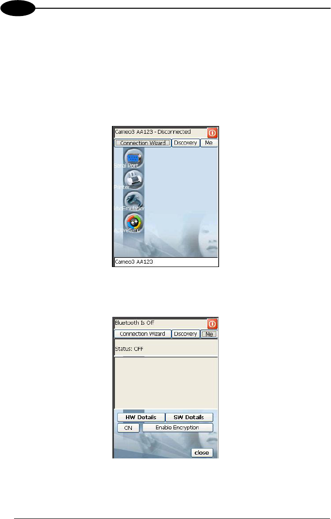
Bluetooth® Manager Device window:
3. Tap on the “Me” button to enter the related window; then, tap on the “ON” button
to activate the Bluetooth® module. The module activation may be also performed
by using the WIRELESS COMMUNICATION applet as described in par. 3.7.4.
By tapping on the “HW Details” and “SW Details” buttons, information about the
mobile computer Bluetooth® hardware and software will be displayed, while the
USE AND FUNCTIONING
43
3
“Enable Encryption” button starts encryption of the Bluetooth® communication
data. If tapping on the “Close” button the Bluetooth® Manager Device window will
be closed.
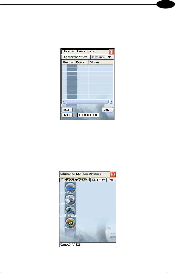
4. Tap on the “Discovery” button to enter the related window; then, tap on the
“Scan” button to run the Discovery procedure:
Once the Discovery procedure has been completed, select the desired
Bluetooth® device from the list. It is also possible to digit (12 hexadecimal digits)
the Bluetooth® address of the desired device by tapping on the “Add” button. The
“Clear” button deletes all discovered devices from the list.
5. Once the desired Bluetooth® device has been selected, tap on the “Connection
Wizard” button to enter the related window where selecting the connection type
to be used for communication with the Bluetooth® device:
The “Serial Port” button starts communication through the Bluetooth® serial port
COM 5 (typically used for connection with GPS devices).

KYMAN-NET™
44
3
The “Printer” button starts communication with a printer through the Bluetooth®
serial port COM 5.
The “Kbd Emulation” button allows connection with a barcode reader using the
keyboard emulation.
The “ActiveSync” button starts communication with a PC equipped with a
Bluetooth® antenna and the related ActiveSync.
6. Hide the Bluetooth® Manager Device window by tapping on the icon
available on each window or close it through the “Close” button available in the
“Me” window (see step 3 of this procedure).

USE AND FUNCTIONING
45
3
3.9 BACKUP DIRECTORY FILE MANAGEMENT
All of the Windows CE .NET system files reside in RAM (volatile memory) except for
the Backup directory, which resides in FLASH (non-volatile memory). Therefore the
contents of the Backup directory are persistent even if the mobile computer is re-
booted or the battery pack is changed.
You can save your more important files that you don't want to lose due to mobile
computer re-boot, in the Backup directory or create a sub-directory within Backup.
Even though the Windows Directory resides in RAM, it often contains files or sub-
directories created by the user or by installation programs that you don't want to lose
at re-boot. To keep these files persistent it is necessary to copy them to the directory
\Backup\Windows. This directory doesn't exist originally (only Backup exists), and
therefore it must be created. At the next hardware reset, before activating the shell,
Windows CE .NET will copy the contents including all sub-directories of
\Backup\Windows to \Windows.
Likewise, to maintain files that must be run at Windows CE .NET startup, (i.e. .exe,
.lnk, .vb, .htm, etc.), it is necessary to copy them to the directory \Backup\Startup.
This directory does not exist originally (only Backup exists), and therefore it must be
created. The application programs will be run after any type of re-boot (both software
and hardware reset).
As an alternative to the Safe Setup function, it is possible to copy the .cab files to the
directory \Backup\Cabfiles (the Cabfiles sub-directory doesn't exists originally and
must therefore be created) and perform a mobile computer cold boot to have the
application installed. Once these files are copied to the directory \Backup\Cabfiles,
the application will be run after each re-boot.
From the second cold boot on, a message may be displayed such as "<application
name> is already installed. Re-install?". This message blocks the boot process.
Press the [Enter] key to continue the system initialization.
KYMAN-NET™
46
4
4 MAINTENANCE
NOTE
Rechargeable battery packs are not initially charged. Therefore the
first operation to perform is to charge them. See below.
4.1 CHARGING THE BATTERY PACK
The battery pack autonomy varies according to factors, such as the frequency of
barcode scanning, RF usage, etc.
When the battery pack is low, the LED positioned at the right side of the display
blinks orange.
It is possible to recharge the battery pack by using the FPS-18 AC/DC external
power supply directly connected to the Kyman-NET™, see par. 2.1.1.
Alternatively, it is also possible to recharge the battery pack by using the
Kyman-NET™ Single Cradle Desk or the Kyman-NET™ Vehicle Cradle.
During the charging process the LED positioned at the right side of the display is red
constant. Once the charging process has been completed this LED is green constant
(see par. 3.5).
If the battery pack is removed from the mobile computer, it can be recharged by
inserting it into the Kyman-NET™ Multi-Battery Pack Charger.
CAUTION
If the battery pack is new or has not been recharged for a long time,
it is necessary to perform two or three charging and discharging
cycles (complete use) before it can reach its maximum charge
capability.
The maximum time required to recharge a completely run-down
battery pack is about 3 hours if the mobile computer is idling.
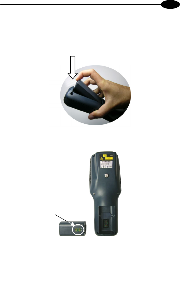
MAINTENANCE
47
4
4.2 REPLACING THE BATTERY PACK
To correctly replace the battery pack, proceed as follows.
1. Turn off the Kyman-NET™.
2. Pull the battery latch down as indicated in the figure below.
3. Remove the battery pack.
Battery Contacts
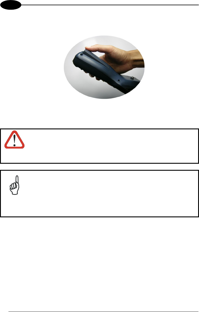
KYMAN-NET™
48
4
4. To correctly insert the new battery pack, first insert the bottom and then the
upper part of the battery pack into the slot as indicated in the following figure:
5. Press it back until the battery latch is automatically closed.
WARNING
Do not incinerate, disassemble, short terminals or expose to
high temperature. Risk of fire, explosion. Use specified charger
only. Risk of explosion if the battery is replaced by an
incorrect type. Dispose of the batteries as required by the
relevant laws in force.
NOTE
In order to guarantee an adequate operating autonomy, when
replacing the battery pack the mobile computer checks the battery
energy level. If the battery is not sufficiently charged, Kyman-NET™
does not turn on (when pressing the ON button).
In this case, either substitute the battery pack with a charged one
(sufficiently charged) or insert Kyman-NET™ into a powered cradle
or plug it into the direct power supply.
MAINTENANCE
49
4
4.3 COMPACT FLASH AND SECURE STORAGE CARDS
The Kyman-NET™ supports both Compact Flash and Mini Secure Digital storage
cards.
The Mini Secure Digital storage card slot accepts Mini storage cards only, while the
CompactFlash card slot accepts either a storage card or the 802.11b radio card.
To install a Compact Flash or a Mini Secure Digital storage card, it is recommended
to contact a Datalogic representative for technical assistance since to access both
cards slots it is necessary to open the mobile computer by removing its screws and
causes warranty loss.
CAUTION
Opening the Kyman-NET™ may damage internal components.
4.4 CLEANING THE MOBILE COMPUTER
Periodically clean the Kyman-NET™ with a slightly dampened cloth.
Do not use alcohol, corrosive products or solvents.
KYMAN-NET™
50
5
5 TECHNICAL FEATURES
5.1 TECHNICAL DATA
Kyman-NET™ Common Features
Electrical Features
Power
DC supply 14 V ± 5%
Battery pack 2 cell Li-Ion 2200 mAh@ 7.4 V (nominal)
Internal backup battery Rechargeable Li-Ion 30 mAh
Communication Features Windows CE.NET COM Port
Serial interface RS232
USB 1.1
COM1
COM6
Wireless Features
WLAN IEEE 802.11b DSSS
WPAN Bluetooth® IEEE 802.15
WWAN GSM/GPRS Tri-band (900, 1800, 1900 MHz)
Radio with accessible SIM card interface
Environmental Features
Working temperature* -20° to + 50 °C / -4° to +122 °F
Storage temperature -20° to +70 °C / -4° to +158 °F
Humidity 90% non condensing for temperatures<40°C
Protection IP64
ESD protection 4 KV contact discharge, 8 KV air discharge
Drop resistance 1.5 m / 5 ft
Hardware Features
FLASH 64 MB
RAM 64 MB
Microprocessor Intel XScale PXA 255 400 MHz
Audio Speaker, Microphone, Buzzer
LED Two-color Programmable LED
Charging Status (two-color LED)
Good Read LED
Display 64K Color TFT LCD with 320 x 240 pixel resolution,
with LED backlight and touch screen
Keyboard 53 or 36 Plastic Top Backlit Keys
Mechanical Features
Dimensions (LxWxH) 24 x 9.2 x 5.5 cm / 9.4 x 3.6 x 2.2 in
Weight (depending on model) 540 - 570 g / 19.0 - 20.1 oz (incl. battery)
* Batteries must be charged at a temperature ranging from 0° to +45 °C (+32° to +113 °F).
TECHNICAL FEATURES
51
5
Programming Features
Operating system Windows CE .NET 4.2
Laser Models (XXX-1XX)
Decoded barcodes 1D UPC A, UPC E, EAN 8, EAN 13, Code 39, Code 39
Full ASCII, Code 32, Interleaved 2 of 5, Industrial 2 of
5, Matrix 2 of 5, Code 128, EAN 128, Codabar, MSI,
Plessey, Code 93, Code 11
Imager Models (XXX-7XX)
Decoded barcodes 1D UPC A, UPC E, EAN 8, EAN 13, UPC/EAN/JAN,
Interleaved 2 of 5, Code 39, Code 39 Full ASCII,
Codabar, Code 128, EAN 128, Code 93, RSS
Decoded barcodes 2D PDF417, DataMatrix, QR, MacroPDF
Postal codes POSTNET, PLANET, Japan Post, Australia Post, KIX
Code, Royal Mail Code (RM4SCC)
Laser Extra Long Range Models (XXX-6XX)
Decoded barcodes 1D UPC A, UPC E, UPC E1, EAN 8, EAN 13, Code 128,
EAN 128, Code 39, Code 39 Full ASCII, Code 32,
Code 93, Interleaved 2 of 5, discrete 2 of 5, Codabar,
MSI, RSS
RFID Models (XXX-X2X)
Philips Mifare Classic 1k (block mode only), Philips
Mifare Classic 4k (block mode only), Philips Mifare
Ultralight (block mode only), Philips I-Code Sli
ISO15693, Texas Tag-It ISO15693, Infineon
ISO15693
Laser Miniature+RFID Models (XXX-42X)
UPC A, UPC E, EAN 8, EAN 13, Code 39, Code 39
Full ASCII, Code 32, Interleaved 2 of 5, Industrial 2 of
5, Matrix 2 of 5, Code 128, EAN 128, Codabar, MSI,
Plessey, Code 93, Code 11
Philips Mifare Classic 1k (block mode only), Philips
Mifare Classic 4k (block mode only), Philips Mifare
Ultralight (block mode only), Philips I-Code Sli
ISO15693, Texas Tag-It ISO15693, Infineon
ISO15693

KYMAN-NET™
52
5
Kyman-NET™ Laser Optical Features
Laser Optical Features
Kyman-NET™
XXX-1XX Models
Kyman-NET™
XXX-4XX Models
Kyman-NET™
XXX-6XX Models
Maximum resolution 0.13 mm / 5 mils 0.13 mm / 5 mils 0.2 mm / 7.5 mils
Skew angle ± 55° ± 65° ± 60°
Pitch angle ± 65° ± 55 ± 65°
Scan rate - horizontal 35 ± 5 scan/sec 50 ± 6 scan/sec 40 ± 6 scan/sec
Depth of field See reading diagrams on the next page
Light source laser
scanner
VLD, wavelength 630~680 nm
Safety class Class II EN 60825-1/CDHR
Kyman-NET™ Imager Optical Features (XXX-7XX models)
Imager Optical Features
Max. resolution
1D Codes 0.10 mm / 4 mils
2D Codes 0.17 mm / 6.6 mils
Skew angle ± 40 °
Pitch angle ± 35°
Depth of field*
1D (linear): X-dimension
mm (mils)
Symbol size
cm (in)
DOF
cm (in)
Code39 0.13 (5) 1.2 (0.47) 8.0 to 15.0 (3.15 to 5.90)
0.50 (20) 3.2 (1.26) 8.0 to 33.0 (3.15 to 12.99)
EAN13 0.33 (13) 3.1 (1.22) 7.5 to 24.5 (2.95 to 9.65)
2D: X-dimension
mm (mils)
Symbol size
cm (in)
DOF
cm (in)
POSTNET 0.5 (20) 4.0 x 0.4 (1.57 x 0.16) 11.5 to 30.0 (4.53 to 11.81)
PDF417 0.13 (5) 1.1 x 0.9 (0.43 x 0.35) 8.5 to 15.5 (3.35 to 6.10)
0.17 (6.6) 1.4 x 1.2 (0.55 x 0.47) 7.0 to 19.0 (2.76 to 7.48)
0.25 (10) 2.2 x 1.8 (0.86 x 0.71) 4.5 to 24.0 (1.77 to 9.45)
QR 0.25 (10) 0.7 x 0.7 (0.28 x 0.28) 7.0 to 15.5 (2.76 to 6.10)
0.38 (15) 1.1 x 1.1 (0.43 x 0.43) 4.5 to 21.0 (1.77 to 8.27)

TECHNICAL FEATURES
53
5
Imager Optical Features
DataMatrix 0.19 (7.5) 0.8 x 0.8 (0.31 x0.31) 9.0 to 13.0 (3.54 to 5.12)
0.25 (10) 0.8 x 0.8 (0.31 x 0.31) 7.5 to 16.5 (2.95 to 6.50)
0.38 (15) 1.0 x 1.0 (0.39 x 0.39) 6.0 to 22.0 (2.36 to 8.66)
Sensor 640 x 480 pixel element, 2D CMOS array
Illuminator LED array
Wavelength 630~670 nm
LED Safety
class
Class 1 to EN 60825-1
Aiming System Visible Laser Diode
Wavelength 650 nm
Laser Safety
class
Class 2 EN 60825-1; Class II CDHR
*Reading distances are measured from the nose of the reader.
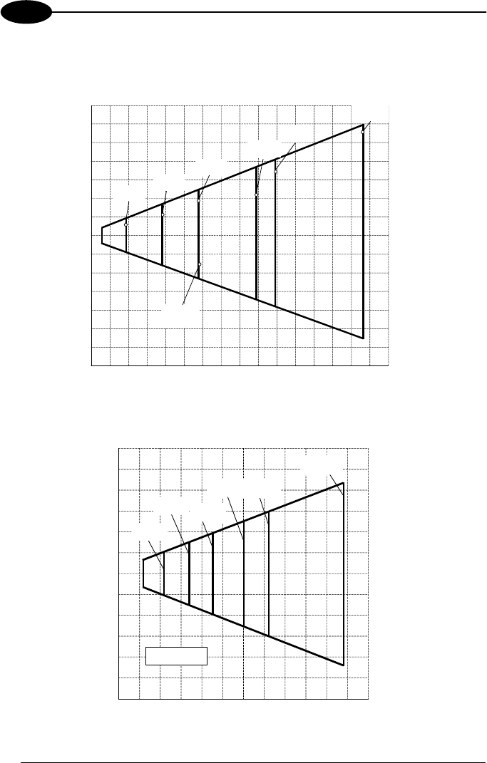
KYMAN-NET™
54
5
5.2 READING DIAGRAMS
Kyman-NET™ HP Laser (XXX-1XX models)
Reading Zones (10° skew angle)
100 200 400
200
100
0
100
200
300 500 600 700 800 mm
300
mm
300
1.00 mm
(40 mils)
0.13 mm
(5 mils)
0.19 mm
(7.5 mils)
0.25 mm
(10 mils)
EAN
0.33 mm
(13 mils)
0.38 mm
(15 mils)
0.50 mm
(20 mils)
Kyman-NET™ RFID +Laser (XXX-4XX models)
100 200 400
200
100
0
100
200
300 500 600 mm
Reading Zones (10° skew angle)
300
mm
300
0.13 mm
(5 mils)
0.19 mm
(7.5 mils)0.25 mm
(10 mils)
0.38 mm
(15 mils)
0.50 mm
(20 mils)
1.00 mm
(40 mils)
on Code 39
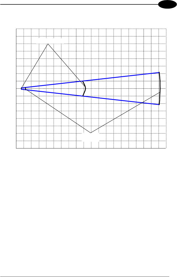
TECHNICAL FEATURES
55
5
Kyman-NET™ XLR (XXX-6XX models)
20 60 100 300 340
120
40
0
40
120
cm
220 260
0.50 mm (20 mils)
1 mm
(40 mils)
380 cm
Reading Zones (10° skew angle)
140 180
60
20
20
60

KYMAN-NET™
56
6
6 TEST CODES
High Density Codes
0.25 mm (10 mils)
Code 39
!17162H!
17162
2/5 Interleaved
Ë"8NduÌ
0123456784
Code 128
ÌtestwÎ
test
80%
EAN 13 x(0B2DE5*KKKKLM(
80%
EAN 8 (6450*TRMN(

TEST CODES
57
6
Medium Density Codes
0.38 mm (15 mils)
Code 39
!17162H!
17162
Interleaved 2/5
Ë"8
NduÌ
0123456784
Code 128
ÌtestwÎ
test
100%
EAN 13 x(0B2DE5*KKKKLM(
100%
EAN 8 (6450*TRMN(

KYMAN-NET™
58
6
Low Density Codes
0.50 mm (20 mils)
Code 39
!17162H!
17162
Interleaved 2/5
Ë"8NduÌ
0123456784
Code 128
ÌtestwÎ
test
120%
EAN 13 x(0B2DE5*KKKKLM(
120%
EAN 8 (6450*TRMN(

59
GLOSSARY
Access Point
A device that provides transparent access between Ethernet wired networks and
IEEE 802.11 interoperable radio-equipped mobile units. Hand-held mobile
computers, PDAs or other devices equipped with radio cards, communicate with
wired networks using Access Points (AP). The mobile unit (mobile computer) may
roam among the APs in the same subnet while maintaining a continuous, seamless
connection to the wired network.
Barcode
A pattern of variable-width bars and spaces which represents numeric or
alphanumeric data in binary form. The general format of a barcode symbol consists
of a leading margin, start character, data or message character, check character (if
any), stop character, and trailing margin. Within this framework, each recognizable
symbology uses its own unique format.
Baud Rate
A measure for data transmission speed.
Bit
Binary digit. One bit is the basic unit of binary information. Generally, eight
consecutive bits compose one byte of data. The pattern of 0 and 1 values within the
byte determines its meaning.
Bluetooth®
A standard radio technology using a proprietary protocol. The onboard Bluetooth
module in the mobile computer is compatible with the 1.1 protocol.
Byte
On an addressable boundary, eight adjacent binary digits (0 and 1) combined in a
pattern to represent a specific character or numeric value. Bits are numbered from
the right, 0 through 7, with bit 0 the low-order bit. One byte in memory can be used to
store one ASCII character.
Decode
To recognize a bar code symbology (e.g., Codabar, Code 128, Code 3 of 9,
UPC/EAN, etc.) and analyze the content of the bar code scanned.
EEPROM
Electrically Erasable Programmable Read-Only Memory. An on-board non-volatile
memory chip.

60
Flash Disk
Non-volatile memory for storing application and configuration files.
GPRS
General Packet Radio Service. GPRS is a wireless packet-based communication
service based on GSM. Its data transfer is rated between 56 Kbps to 114 Kbps. It
makes very efficient use of available radio spectrum, and users pay only for the
volume of data sent and received.
GSM
Global System for Mobile communication. It is a standard for digital cellular
communications, currently used in the 900 MHz and 1800 MHz bands.
Host
A computer that serves other mobile computers in a network, providing services such
as network control, database access, special programs, supervisory programs, or
programming languages.
Liquid Crystal Display (LCD)
A display that uses liquid crystal sealed between two glass plates. The crystals are
excited by precise electrical charges, causing them to reflect light outside according
to their bias. They use little electricity and react relatively quickly. They require
external light to reflect their information to the user.
Light Emitting Diode (LED)
A low power electronic light source commonly used as an indicator light. It uses less
power than an incandescent light bulb but more than a Liquid Crystal Display (LCD).
RAM
Random Access Memory. Data in RAM can be accessed in random order, and
quickly written and read.
RF
Radio Frequency
RFID (Radio frequency identification)
A technology that incorporates the use of electromagnetic or electrostatic coupling in
the radio frequency (RF) portion of the electromagnetic spectrum to uniquely identify
an object, animal, or person. RFID is coming into increasing use in industry as an
alternative to the barcode identification.
RTC
Real Time Clock.

61
INDEX
A
Accessories; 5
Alphanumeric Keyboard; 19
Available Models; 2
B
Backup Directory File Management;
45
Bluetooth® Manager Device Setup;
42
Buttons; 33
C
Charging the Batteries; 46
Cleaning the Mobile Computer; 49
Connection Cables; 12
RS232 Direct Connection; 12
RS232 Power Connection; 13
USB Direct Connection; 12
USB Power Connection; 13
Connections; 6
RS232/USB Direct Connection; 6
WLAN Connection; 7
WPAN Connections; 8
WWAN Connections; 9
Control Panel; 32
Conventions; vii
D
Data Capture; 16
Imager Data Capture; 17
Laser Data Capture; 16
RFID Data Capture; 18
Data Capture Configuration; 27
Default Settings; 30
Description of the Keys; 19
E
End User License Agreement; v
F
Files Admin; 34
G
General View; xv
Glossary; 59
K
Kyman-NET™ Description; 1
M
Maintenance; 46
Microsoft® ActiveSync®; 40
N
Numeric Keyboard; 22
P
Package Contents; 2
R
Reader Parameters; 29
Reading Diagrams; 54
Reference Documentation; vii
References; vii
Registry; 33
Replacing the Batteries; 47
S
Safe Setup; 34
Safety Regulations; viii
Laser Safety; ix

62
Radio Compliance; xiii
Save Session; 34
Scan Parameters; 29
Services and Support; vii
SIM Card; 10
Startup; 14
Status Indicators; 25
T
Technical Features; 50
Test Codes; 56
U
Using the Stylus; 15
V
Vocal Communication; 37
Volume Settings; 37
W
Wireless Communication; 36

05
DATALOGIC S.p.A.,
Via Candini, 2
40012 - Lippo di Calderara
Bologna - Italy
dichiara che
declares that the
déclare que le
bescheinigt, daß das Gerät
declare que el
Kyman-NET XXX-XXX
e tutti i suoi modelli
and all its models
et tous ses modèles
und seine Modelle
y todos sus modelos
sono conformi alla Direttiva del Consiglio Europeo sottoelencata:
are in conformity with the requirements of the European Council Directive listed below:
sont conformes aux spécifications de la Directive de l'Union Européenne ci-dessous:
der nachstehenden angeführten Direktive des Europäischen Rats entsprechen:
cumple con los requisitos de la Directiva del Consejo Europeo, según la lista siguiente:
1999/5/EEC R&TTE
Questa dichiarazione è basata sulla conformità dei prodotti alle norme seguenti:
This declaration is based upon compliance of the products to the following standards:
Cette déclaration repose sur la conformité des produits aux normes suivantes:
Diese Erklärung basiert darauf, daß das Produkt den folgenden Normen entspricht:
Esta declaración se basa en el cumplimiento de los productos con las siguientes normas:
ETSI EN 301 489-17 v1.2.1, August 2002: ELECTROMAGNETIC COMPATIBILITY AND RADIO SPECTRUM MATTERS (ERM);
ELECTROMAGNETIC COMPATIBILTY (EMC) STANDARD FOR RADIO EQUIPMENT
AND SERVICES; PART 17: SPECIFIC CONDITIONS FOR 2,4 GHZ WIDEBAND
TRANSMISSION SYSTEMS AND 5 GHZ HIGH PERFORMANCE RLAN EQUIPMENT
ETSI EN 300 328 v1.6.1, November 2004: ELECTROMAGNETIC COMPATIBILITY AND RADIO SPECTRUM MATTERS (ERM);
WIDEBAND TRANSMISSION SYSTEMS; DATA TRANSMISSION EQUIPMENT
OPERATING IN THE 2,4 GHZ ISM BAND AND USING WIDE BAND MODULATION
TECHNIQUES; HARMONIZED EN COVERING ESSENTIAL REQUIREMENTS UNDER
ARTICLE 3.2 OF THE R&TTE DIRECTIVE
EN 60950-1, December 2001: INFORMATION TECHNOLOGY EQUIPMENT – SAFETY –
PART 1: GENERAL REQUIREMENTS
Lippo di Calderara, 08/09/2005
Ruggero Cacioppo
Quality Assurance Laboratory Manager