Datamatic D4100 Water Meter Interface User Manual
Datamatic, Ltd Water Meter Interface
User Manual

©Datamatic, Ltd. 2007 - 1 -
System Guide
D4100 MOSAIC – Water
Datamatic, Ltd. © 2007

- 2 - ©Datamatic, Ltd. 2007
Table Of Contents
Table Of Contents ..............................................................................................2
Regulatory Information .......................................................................................3
Introduction.........................................................................................................4
Equipment ..........................................................................................................5
D4100 MOSAIC Meter Interface Unit (MIU)...................................................5
D4100 MOSAIC – Wire-end ..........................................................................6
D4100 MOSAIC – Logical Switch ..................................................................6
Lid Lock.........................................................................................................7
Installation Supplies............................................................................................8
Optic Sensor-end D4100 MOSAIC Installation Supplies................................8
Wire-end D4100 MOSAIC Installation Supplies .............................................9
Logical Switch D4100 MOSAIC Installation Supplies...................................10
Installation Considerations................................................................................11
Installation Procedures .....................................................................................12
Installation Overview for Water D4100 MOSAICs........................................12
Wire-end D4100 MOSAIC Installation Procedure ........................................15
Logical Switch D4100 MOSAIC Installation Procedure ................................18
Appendix A – Wire-end D4100 MOSAIC Connections - Encoded Meters....19
Contacting Datamatic .......................................................................................20
System Support during Business Hours ......................................................20
System Support after Business Hours .........................................................20
Paging a Support Representative after Business Hours ..............................21

©Datamatic, Ltd. 2007 - 3 -
Regulatory Information
United States of America, FCC:
Note: This equipment has been tested and found to comply with the limits for a Class B digital
device, pursuant to part 15 of the FCC Rules. These limits are designed to provide reasonable
protection against harmful interference in a residential installation. This equipment generates, uses
and can radiate radio frequency energy and, if not installed and used in accordance with the
instructions, may cause harmful interference to radio communications. However, there is no
guarantee that interference will not occur in a particular installation. If this equipment does cause
harmful interference to radio or television reception, which can be determined by turning the
equipment off and on, the user is encouraged to try to correct the interference by one or more of
the following measures:
--Reorient or relocate the receiving antenna.
--Increase the separation between the equipment and receiver.
--Connect the equipment into an outlet on a circuit different from that to which the receiver is
connected.
--Consult the dealer or an experienced radio/TV technician for help.
FCC ID: ODYD4100
Caution: Changes or modifications not expressly approved by the manufacturer could void
the user’s authority to operate the equipment.
Canada, Industry Canada (IC)
The wireless radio of this device complies with RSS 210 Industry Canada. This Class B digital device
complies with Canadian ICES-003.
The installer of this radio equipment must ensure that the antenna is located or pointed such that it does
not emit RF field in excess of Health Canada limits for the general population; consult Safety Code 6,
obtainable from Health Canada’s website www.hc-sc.gc.ca/rpb

- 4 - ©Datamatic, Ltd. 2007
Introduction
The D4100 MOSAIC System is an automatic meter reading system designed for reading meter data
remotely and wirelessly. This is accomplished using the Datamatic D4100 MOSAIC Meter Interface
Unit (MIU) that forms a mesh network with neighboring D4100 MOSAIC MIUs, and reports data to the
Home Office (HO) through strategically placed gateway devices.
The main benefits of using a D4100 MOSAIC System are:
• Real-time access to meter readings
• Built-in logging of 72+ days of consumption data
• Complete remote control of MIUs through MOSAIC Software Interface
• Meter lids do not have to be removed for reads
• Meter pits do not have to be dug out or pumped out for reads
• Increased accuracy of meter readings
• Safer meter reading procedure
• Visiting the site is not necessary for data collection
Please consult the MOSAIC Software Interface Guide for user instructions regarding data access,
configuring, or upgrading the D4100 MOSAIC. After reviewing this guide you should be able to
successfully deploy the D4100 MOSAIC for your application.

©Datamatic, Ltd. 2007 - 5 -
Equipment
D4100 MOSAIC Meter Interface Unit (MIU)
The D4100 MOSAIC Meter Interface Unit (MIU) tracks and transmits meter reading data. Each D4100
MOSAIC can be configured to record 72+ days of hourly consumption readings, thereby enabling the
resolution of billing disputes. The D4100 MOSAIC signal includes the meter number, meter reading,
battery voltage, tamper flag, and a leak indicator.
Battery: 3.6-volt lithium chloride D-cell
Material: Polycarbonate
Construction: Ultrasonic welding
Operating Temperature Range: -40°F to 185°F
Radio Communication Frequency: 902 - 928 MHz
D4100 MOSAIC – Optic Sensor-end
This D4100 MOSAIC uses an optical sensor unit to track meter activity. The infrared sensor is oriented
so that the register needle approaches the sensor from the cable side and perpendicular to the cable. The
indicators on the top side of the sensor need to be aligned with the passing sweep hand. As the needle
sweeps past the sensor, it changes the light reflected back from the meter face, and an incremental count
is registered. The optical sensor is affixed to the meter face using a high-bond adhesive tape.
Unique Features:
• Use existing meters.
• The D4100 MOSAIC Optic Sensor Model is the only available technology for automating
meters without electronic registers
• Ultrasonically-welded, seamless construction designed to withstand constant submersion
• Leak Detection
• Tamper Detection
• Battery Status Indicator
Optical Sensor Tape Specification
Manufacturer: 3M
Part Number: 4951VHB
Minimum Application Temp: 33°
°°
° Fahrenheit
Curing Time: 24 hours
- 6 - ©Datamatic, Ltd. 2007
D4100 MOSAIC – Wire-end
The D4100 MOSAIC for water meters installs in under five minutes on virtually any meter. Wired-end
Model D4100 MOSAIC's support all the popular pulse and encoder registers. The D4100 MOSAIC
eliminates the need for meter changeout for the purpose of AMR implementation and can save utilities
millions of dollars in meters and installation labor.
Unique Features:
• Use existing meters.
• Maintain the freedom to choose meters without the constraints of proprietary AMR system.
• Ultrasonically-welded, seamless construction designed to withstand constant submersion
• Accommodates direct-read, pulse and encoded registers
• Leak Detection
• Tamper Detection
• Battery Status Indicator
• Above ground, below ground or through-the-lid installation
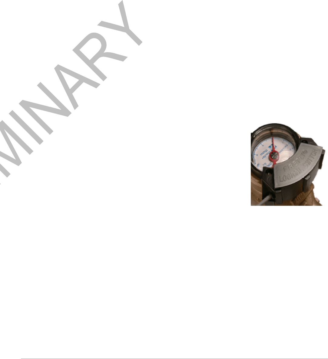
D4100 MOSAIC – Logical Switch
The D4100 MOSAIC Logical Switch (FFLS) represents another step
forward for the innovative D4100 MOSAIC AMR technology. The FFLS
combines the unshakeable accuracy of an absolute encoder register with the
low cost of a pulse register. It provides an instant interface to Master Meter
"high glass" and similar registers on any size meter, adding one more option
to the D4100 MOSAIC's already Meter Independent approach to
Automatic Meter Reading. The FFLS works by sensing the magnet
embedded in the register's sweep needle. Each revolution sends a signal that
increments the D4100 MOSAIC. The Logical Switch also tracks
REVERSE rotations (backflow)! D4100 MOSAIC readings remain 100%
accurate even under less-than-ideal line conditions. Installation takes only
seconds using a standard screwdriver.
D4100 MOSAIC Logical Switch on Master Meter
Unique Features:
• Encoder performance without the cost
• Interfaces to Master Meter "high glass" and similar registers - all meter sizes
• Tracks forward and reverse flow with 100% accuracy
• Connects directly to D4100 MOSAIC Water MIU in less than 1 minute
• Can be ordered pre-potted to D4100 MOSAIC Water MIU
• No power required

©Datamatic, Ltd. 2007 - 7 -
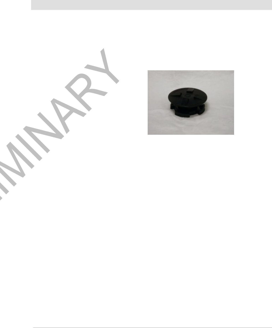
Lid Lock
If the lid has a hole for the unit, use the cap and wing nut assembly
(“lid lock” pictured at right). Ensure that enough space exists
between the box lid and the ground for the unit to sit. If not,
remove some of the dirt from the bottom of the box.
Do not over tighten lid locks.
D4100 MOSAIC Lid lock
- 8 - ©Datamatic, Ltd. 2007
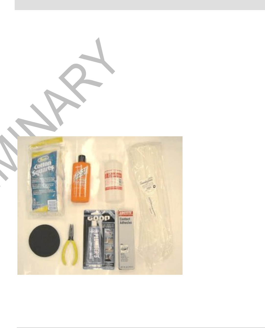
Installation Supplies
Optic Sensor-end D4100 MOSAIC Installation Supplies
Basic Supplies:
• Razor blade tool or chisel
• Non Pumice Fast Orange 7.5 Fl. Oz Part No. 23108
15 Fl Oz. Part No 23116
• Cloth Rags
• 99% Isopropyl Rubbing Alcohol
• Lint Free Cotton Squares
• Plumber’s Goop Adhesive #15112 (Purple Tube)
• Zip Ties—14”
• ¾” PVC pipe; sch. 40
• Sensor flaps
• Wire Cutter (for cutting zip ties)
• 9 Volt Battery
• 3M Adhesive Replacements
Below is an illustration of materials used with Sensor-end installations:

©Datamatic, Ltd. 2007 - 9 -
Wire-end D4100 MOSAIC Installation Supplies
Water Pit Splice Supplies:
Following is a list of materials required to install a wire-end D4100 MOSAIC using the Water Pit
Splice technique:
• Devcon Mark 5 epoxy gun for 50ml cartridge
• Mixing Nozzle for Gun #14285
• UY connectors
3M IDC Connector-Yellow Part No. 34-7035-9854-9
3M IDC Connector- Red Part No. 78-8064-7439-7
AMP Tel-Splice Connector 2 Wire 19-26 AWG-Part No. 1-552795-2
AMP Tel-Splice Connector 3 Wire 19-26 AWG-Part No. 1-552678-2
• Burial pod
UY connector/Burial pod combination Connector Kings Corp 800-822-6608.
3-3M UY Meter Kit SA1013E {3-3M Gels for each plastic pod}
3M Direct Burial Splice Pod – Part No. 054007-09964 (0110 firmware Wire-end D4100
MOSAIC or higher)
• Devcon Polystrate 2 Ton Epoxy Cartridge #14260
• 2-ton Epoxy Devcon Polystrate 2-ton epoxy 14260 www.devcon.com (to locate a local
distributor.)
• Loctite Quick Set Epoxy gel QM-50 81501 (can locate local distributor.)
Lowe’s local hardware store www.LOWES.com and go to the “Store Locator” to find a local
store.
NOTE: All supplies for Water Pit Splice method can be purchased from:
Datamatic.com, Ltd. 888-326-5032 or 972-234-5000 www.Datamatic.com
Below are illustrations of materials used with the Water Pit Splice technique:

- 10 - ©Datamatic, Ltd. 2007
Basement Splice Supplies:
Following is a list of materials required to install a wire-end D4100 MOSAIC using the Basement
Splice technique:
• UY connectors or Posi lock connectors
Distributors such as Home Depot, Lowe’s, Graybar, Fastenal, Parts Associates
• 3M Scotch 2200 Vinyl Mastic Pads
www.3m.com (to locate local distributor)
NOTE: All supplies for Water Pit Splice method can be purchased from:
Datamatic.com, Ltd. 888--326-5032 or 972-234-5000 www.Datamatic.com
Below is an illustration of materials used with the Basement Splice Technique:
Basic Supplies:
• Kline Krimping Tool Part No. D2346
• Wire Stripper
• Zip ties, White, 14”
• 9 Volt Battery
• ¾” PVC pipe; sch. 40
Logical Switch D4100 MOSAIC Installation Supplies
Basic Supplies:
• Cross-tipped screwdriver
• Cloth rags
• Zip ties, White, 14”
• ¾” PVC pipe; sch. 40
• 9 Volt Battery
©Datamatic, Ltd. 2007 - 11 -
Installation Considerations
1. Signal distance varies depending on the location of the D4100 MOSAIC. Those installed above
ground generally transmit the greatest distance.
2. The material of a pit or vault lid affects the transmission range. For example, a transmitter has a
greater range sending from a pit with a plastic lid than a cast iron lid.
3. Lids with holes of a diameter of roughly 1 3/4 inches make it possible to mount the D4100
MOSAIC through the lid. This can increase transmission range significantly.
4. Complete field installation of a D4100 MOSAIC takes 5-10 minutes, depending on the meter
location and mounting application.
5. If the lid has a hole for the unit, use the cap
and wing nut assembly (“lid lock” pictured
at right). Ensure that enough space exists
between the box lid and the ground for the
unit to sit. If not, remove some of the dirt
from the bottom of the box. Do not over-
tighten lid locks.

- 12 - ©Datamatic, Ltd. 2007
Installation Procedures
Installation Overview for Water D4100 MOSAICs
1. Perform a site survey to determine where best to install the Gateway devices and where to
designate MIU mesh network areas.
2. Configure MIUs before on site installation with the unique mesh word to form a group of
selected MIUs into a mesh network.
3. Prepare the meter.
4. Attach the D4100 MOSAIC.
5. Using a mobile gateway, take a reading to verify neighbor MIUs on the mesh.
6. Once the entire route is installed, verify connectivity from the installed gateway to the Home
Office.
#1 Preparation Of the Meter
1. Remove meter box lid.
2. Survey the meter, checking lid, hole depth, and overall cleanliness.
3. Check for meter disqualification.
4. Place sensor flap onto D4100 MOSAIC cable.
5. Flip lid back and pre-clean meter face/lens using Fast Orange non-pumice cleaner and a cloth or
cotton swab to remove residue.
6. Clean meter face/lens with 99% isopropyl alcohol and a NEW lint-free cotton swab.
7. Re-wipe the surface of the meter lens with a clean, new cotton swab each time until the swab
comes up clean, and the clean lens squeaks when wiped.
8. After cleaning, ensure that the lens is completely dry; allow time for the alcohol to evaporate.
NOTE: Only use isopropyl rubbing alcohol marked “99% by volume”. Lower concentrations, such as
the commonly available 91%, do not clean or evaporate well and adversely affect sensor-to-meter bond.
#2 Placement of the Sensor
1. Insert sensor cable through sensor flap.
2. Remove the adhesive backing from the high-bond tape on the optic sensor face.
3. Orient the sensor so the water meter needle approaches the sensor from the cable side and
perpendicular to the cable. There are indents on each side of the sensor base that are to be in line with
the needle when it passes. Do not place the sensor over any moving part or the sweep hand of the
register. Normally, place sensor along outer edge of register.
NOTE: Do not place the sensor over any moving part or the sweep hand of the register. Normally, place
sensor along outer edge of register.
Here is an example of correct Sensor Placement:

©Datamatic, Ltd. 2007 - 13 -
#3 Pressure – To the Sensor on the Meter
NOTE: Since the 3M tape provides a pressure sensitive seal, the installer must apply 15 lbs. of
pressure to the D4100 MOSAIC optical sensor immediately after attaching to the lens surface for a
minimum of 60 seconds.
1. Very Important: Press the adhesive down for 60+ seconds using 15 lbs of pressure. Allow 24-96
hours to cure.
2. Fasten the cable to the register with a zip tie.
3. Place Goop-Plumber’s Adhesive #15112 (purple tube) around the metal edge sensor and under the
tail of the sensor. Do not squirt the adhesive UNDER the 3M seal. The goal is to provide a
temporary water barrier between the meter face and the metal edge of the sensor, so that the 3M
adhesive can cure properly.
4. Position the flap at the base of the sensor so that it folds over and “hangs” above the register to try to
keep most of the stray light out while it processes through AutoCAL. The flap will be “pulled” over
the sensor snuggly lying flatter on the meter during the Read and Verify procedure that will be
discussed later.
- 14 - ©Datamatic, Ltd. 2007
Final Optic Sensor-end D4100 MOSAIC Installation Steps
1. A full cure on the seal is achieved in 24-96 hours. Do not touch, pull, move, or handle the sensor in
any way during this period.
2. Mount the D4100 MOSAIC box with the threaded neck pointing up.
3. Mounting can be accomplished by attaching to a wall, stake, or through a hole in the meter box or
vault.
4. Typical meter pits will use an 18” long ¾” PVC stake. Push the stake into the ground approx. 6”
deep, adjacent to the meter register.
5. Attach the D4100 MOSAIC to the stake with the zip ties (6” or 14”).
6. If utilizing a lid lock, make certain not to over-tighten the D4100 MOSAIC within the lock.
7. Check for lid clearance; be sure to never rest the weight of the meter lid on the D4100 MOSAIC.
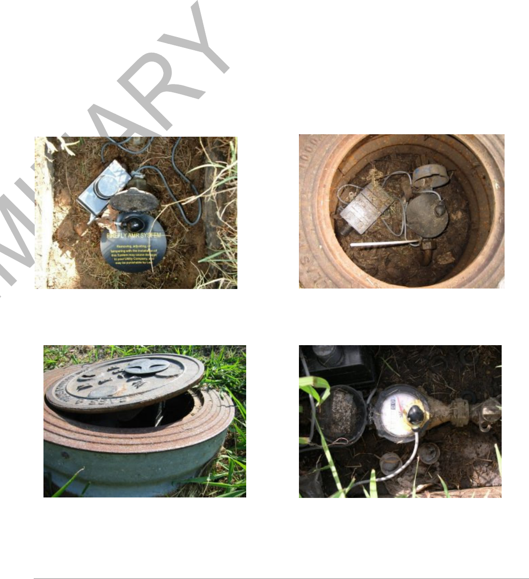
D4100 MOSAIC Installation pictures:
Example of a GOOD Sensor-end Installation. Example of a BAD Sensor-end Installation.
What is wrong here? ____________________
Example of a BAD Sensor-end Installation. Example of a BAD Sensor-end Installation.
What is wrong here? ____________________ What is wrong here? _____________________
©Datamatic, Ltd. 2007 - 15 -
Wire-end D4100 MOSAIC Installation Procedure
Refer to Appendix D & E to determine wire the correct connection for the brand and model of meter.
#1 Set the Reading Mode
• Set D4100 MOSAIC reading mode to Verify Mode.
#2 Wire Connections
Connect the wires with the D4100 MOSAIC and meter using the schematics below:
Schematics: Write in the Wire Color Combinations Below
D4100 MOSAIC
Meter
Schematics: Write in the Wire Color Combinations Below
D4100 MOSAIC
Meter
Connect the wires using UY gel cap connectors. If the wires are stripped, cut off the stripped ends.
Wires must have unstripped ends for use in gel cap connectors. Use the Klein crimping tool to secure the
gel cap connectors.
Below is an illustration of the wires spliced using the UY gel cap connectors:
NOTE: Once connected to the encoded register, test the D4100 MOSAIC connections by programming
the unit and receiving the encoded setup message.
Pulse output registers do not have pre-install test capabilities. Therefore, be sure to have wires
connected properly prior to filling pods with epoxy.
#3 Splice Methods
Water Pit Splice Method using burial pods:
• Fill the burial pod halfway to two-thirds full with epoxy.
• Insert the UY connections into the burial pod so that cables come out of either side.
• Completely fill the empty space left in the pod with approved 2-ton epoxy.
• Tap to make any air bubbles rise to the top.

- 16 - ©Datamatic, Ltd. 2007
• Snap the burial pod shut and allow 30 minutes of drying time.
Below are examples of approved Burial Pods that can be used with the Wire-end D4100 MOSAIC:
3M Direct Burial Splice Pod UY connector/Burial pod combination
Firmware 011 & 0111 Firmware 0106-0109
Below is an illustration of the water pit splice method including the meter and D4100 MOSAIC:
Water Pit Splice Method for Direct Register Connections:
• Strip the wires back 4 inches.
• Cut excess wires and direct connect to meter according to wire connections guide per register type.
• Pod remaining wires in black pod and fill with epoxy per approved method.
Each register terminal and wire connection must be protected from moisture utilizing the Electrical
Insulating Compound specified below.

©Datamatic, Ltd. 2007 - 17 -
DOW CORNING
Mfg. Model #: 4
Distributor: Grainger - Grainger item #: 6Y765
Unit of Measure: 5.3 oz. Tube
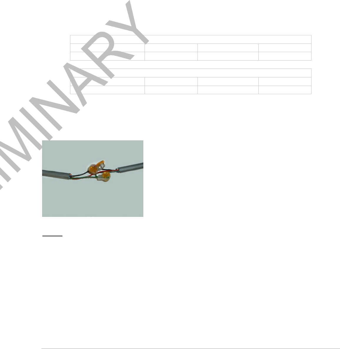
Basement Splice:
• Connect D4100 MOSAIC wires to register cable wires using the UY connectors.
• Space the connections out so that the Mastic pad will cover the entire connection.
• The 3M Scotch Vinyl Mastic Pad can be cut so that one pad covers 2-3 installations depending on
number of wires needed and type of connectors used.
• Be sure there is enough pad to completely cover the connections.
• Due to the nature of the Mastic adhesive, this installation cannot be completed in temperatures below
45 degrees Fahrenheit.
• Once the Mastic adhesive is placed over the splice, it must be squeezed together and molded around
the splice to insure a watertight seal.
Below is an illustration of the wire connections with the Mastic adhesive:

- 18 - ©Datamatic, Ltd. 2007
Logical Switch D4100 MOSAIC Installation Procedure
The D4100 MOSAIC Logical Switch MUST be handled with care at all times. A drop or shock of any kind
could affect the performance of the Logical Switch. The Logical Switch is compatible with D4100 MOSAIC.
#1 Set the Reading Mode
• Set D4100 MOSAIC reading mode to Verify Mode.
#2 Clean the Register
Clean the register with a rag to make sure there is no mud or dirt that would get caught between the
collar and glass.
#3 Attach the Logical Switch to the Register
Place the Logical Switch on the register and secure with the two screws attached on the switch.
Final Logical Switch D4100 MOSAIC Installation Steps
1. Mount the D4100 MOSAIC box with the threaded neck pointing up.
2. Mounting can be accomplished by attaching to a wall, stake or through hole in meter box/vault lid.
3. Typical meter pits will use an 18” long ¾” PVC stake with drilled holes. Push the stake into the
ground approx. 6” deep, adjacent to the meter register.
4. Attach the D4100 MOSAIC to the stake with the zip ties (6” or 14”) utilizing the holes in the PVC.
5. If utilizing a lid lock, make certain not to over-tighten the D4100 MOSAIC within the lock.
6. Check for lid clearance; be sure to never rest the weight of the meter lid on the D4100 MOSAIC.
7. Pick up all trash in and around the pit or installation area.
8. Secure the lid back on the pit.
Initial installation and programming of D4100 MOSAIC is complete. The installation data gathered
should now be emailed to Datamatic. Then, proceed to the Read and Verify Procedure steps.
Below is an example of a Logical Switch D4100 MOSAIC installation:

©Datamatic, Ltd. 2007 - 19 -
Appendix A – Wire-end D4100 MOSAIC Connections - Encoded Meters
Brand Model Register Type FF Wires Meter Wires Comments
ABB/Kent Scancoder Encoded Red Green
Green Red
Black Black
Hersey Translator Encoded Red Red
Green Green 0109 +
Black Black
Master Meter Dialog Encoded Red Green
Green Green 0107 +
Black Red
Metron Prolink Encoded Brown Red
White Green
Black Black
Neptune T-8 Encoded Red 1 post
If dials have 2
cards
= ARB 5
Green 2 post
If dials have 3 cards,
can =
Black 3 post ARB 5 or ARB 6
Neptune AUTO Encoded Red Black
Green Red 0109 +
Black Green
Rockwell ECR Encoded Red Red
3 wire Green Green
Black Black
Rockwell ECR Encoded Red Red
2 wire Green Red
Black Black
Rockwell Touchread Encoded Red Red
3 wire Green Green
Black Black
Rockwell Touchread Encoded Red Red
2 wire Green Red
Black Black
Schlumberger ARB V Encoded Red Black
Green Red
Black Green
Schlumberger ARB VI Encoded Red Black
Green Red
Black Green
Schlumberger AUTO Encoded Red Black
Green Red 0109 +
Black Green
Sensus SR II Encoded Red Red
3 wire Green Green
Black Black
Sensus SR II Encoded Red Red
FF Red and Green
together

- 20 - ©Datamatic, Ltd. 2007
2 wire Green Red to Meter Red
Black Black
Invensys AMR System Encoded Red Red
Green Green
Black Black
Neptune E-coder Encoded Red Black Program as a
Green Red Neptune Auto
Black Green
Badger Absolute Encoder Encoded Red Red
Green Green
Black Black
Metron Spectrum 22 Encoded Red Red Program as a
Green Green Sensus SRII 3-wire
Black Black
AMCO InVision Encoded Red Green
White Red
Black Black
Invensys/Sensus ICE Encoded Red Red Program as a
Green Green Sensus SRII 3-wire
Black Black
Contacting Datamatic
Datamatic, Ltd. offers the following benefits to customers under the RouteSTAR MVP Meter Reading
System maintenance agreement.
24-hour telephone support for MOSAIC Interface Software.
Two-hour response time on telephone calls.
Preventative maintenance on system hardware.
Best effort turn-around time for repairs.
Software updates.
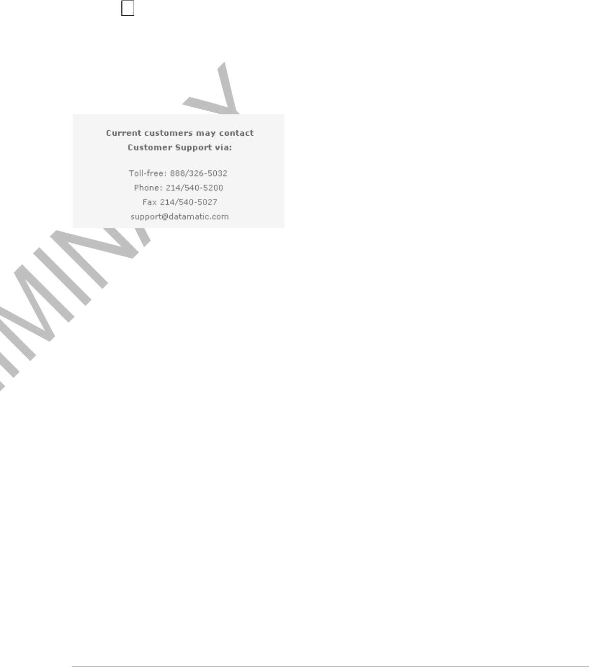
System Support during Business Hours
Support is available to customers of Datamatic, Ltd. from 8:00 AM to 5:00 PM CST. The toll-free
customer support number is (888) 326-5032.
System Support after Business Hours
Customers requiring assistance after Datamatic business hours can leave a message for the
appropriate group. Emergency assistance is available 24 hours a day.
If this is an emergency, press 2 at the greeting to page a Customer Support Representative.
If this is not an emergency and can wait until the next business day, listen for the options to leave a
message.
Leave your name, number, and message at the prompt.
A customer support representative should return your call the next business day.
©Datamatic, Ltd. 2007 - 21 -
Paging a Support Representative after Business Hours
Call the Customer Support number above.
Press 2 to leave an emergency message.
Leave your name, number, and message at the prompt.
A support representative will be paged and return your call within two hours.
For the most timely response, call the Toll Free number (888) 326-5032 from 7:30am to 5:30pm CST or
submit an email. If you call after that time you can leave a message, and someone will call you back
within two hours.
There is also the Support Request Form, which you can fill out and submit. You will receive a response
back from support regarding the information you have entered on this page.