Datapaq TM21 TELEMETRY TRANSCEIVER MODULE User Manual
Datapaq Limited TELEMETRY TRANSCEIVER MODULE Users Manual
UserManual.wiki
>
Datapaq
>
TM21 User Manual
Users Manual
Navigation menu
Upload a User Manual
Namespaces
Wiki Guide
HTML
PDF
Info
Views
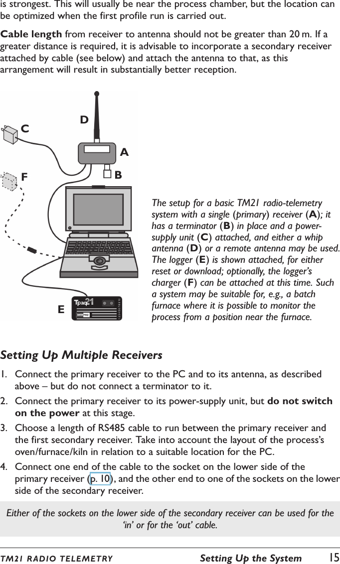
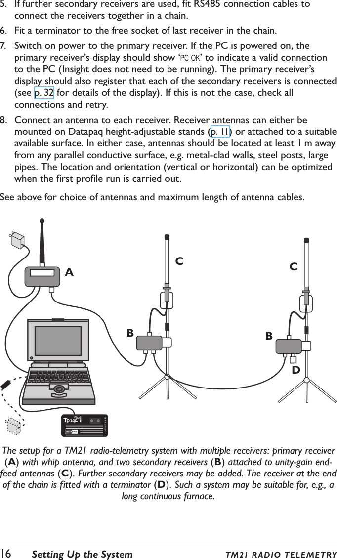
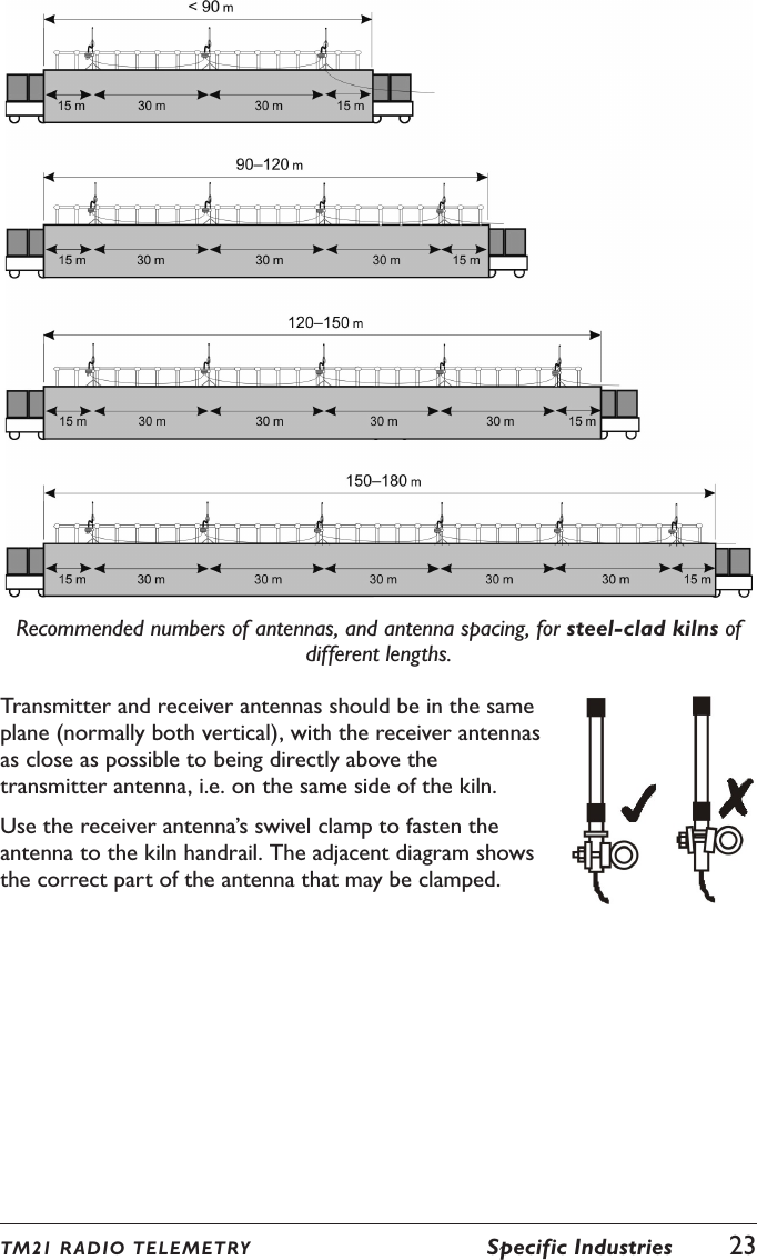
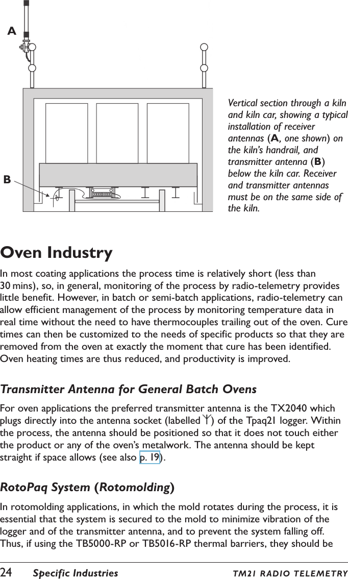
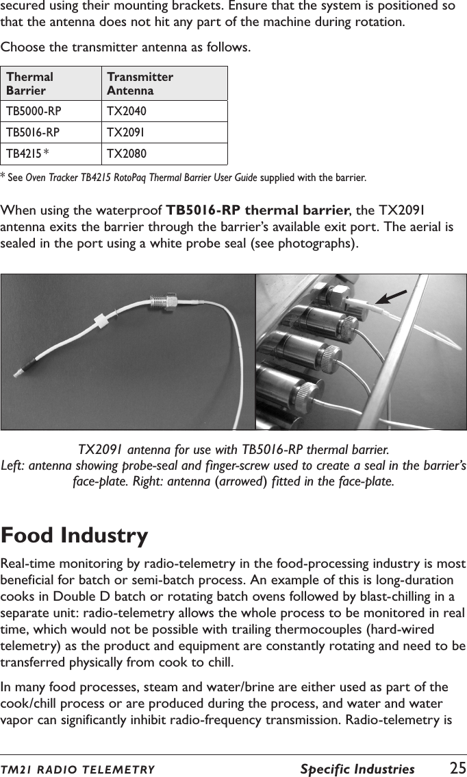
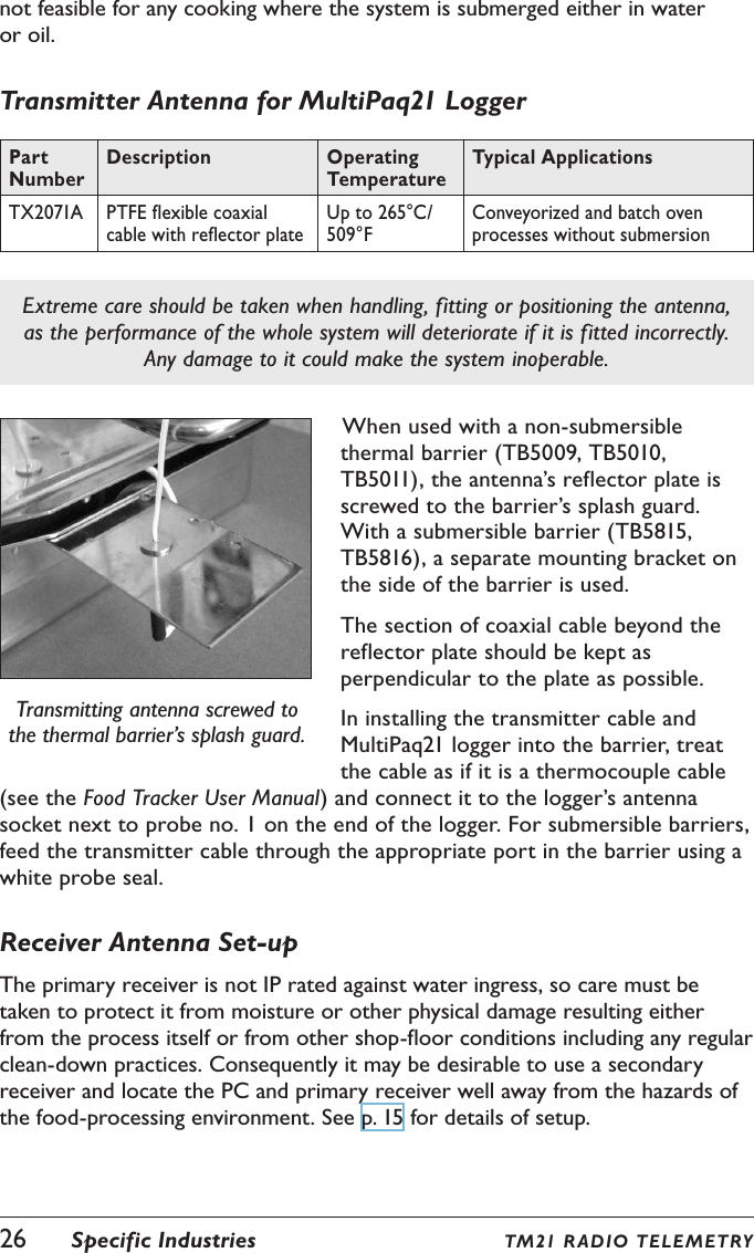
User Manual
Discussion / Help
Navigation