Datapaq TM21 TELEMETRY TRANSCEIVER MODULE User Manual
Datapaq Limited TELEMETRY TRANSCEIVER MODULE Users Manual
Datapaq >
Users Manual

TM21
Radio-
telemetry
System
USER MANUAL
for Datapaq
Tracker Systems
with
Issue 1
MA5940A

TM21
Radio-telemetry
System
for Datapaq Tracker Systems with
User Manual
Issue 1
Europe & Asia
Datapaq Ltd.
160 Cowley Road
Cambridge CB4 0GU
England
Tel. +44-(0)1223-423141
Fax +44-(0)1223-423306
E-mail sales@datapaq.co.uk
www.datapaq.com
North & South America
Datapaq, Inc.
187 Ballardvale Street
Wilmington, MA 01887
USA
Tel. +1-978-988 9000
Fax +1-978-988 0666
E-mail sales@datapaq.com
www.datapaq.com
Datapaq is the world’s leading manufacturer
of process temperature-monitoring
instrumentation. The company maintains
this leadership by continual development
of its advanced, easy-to-use Tracker systems.
DATAPAQ PART NO. MA5940A

© Datapaq Ltd., Cambridge, UK 2010
All rights reserved
Datapaq Ltd. makes no representations or warranties of any kind
whatsoever with respect to the contents hereof and specifically
disclaims any implied warranties of merchantability or fitness for any
particular purpose. Datapaq Ltd. shall not be liable for errors
contained herein or for incidental or consequential damages in
connection with the furnishing, performance or use of the Datapaq
software, associated hardware or this material.
Datapaq Ltd. reserves the right to revise this publication from time to
time and to make changes to the content hereof without obligation to
notify any person of such revisions or changes.
Microsoft and Windows are registered trademarks
of Microsoft Corporation.
Manual set in 10 pt Gill Sans.
User manuals are available in other languages;
contact Datapaq for details.
SAFETY WARNINGS
For safe use of Datapaq equipment, always:
•Take care to follow its supplied instructions.
•Observe any warning signs shown on the equipment itself.
Indicates potential hazard.
On Datapaq equipment this normally warns of high
temperature, but where you see the symbol you should
consult the manual for further explanation.
Warns of high temperatures.
Where this symbol appears on Datapaq equipment, the
surface of the equipment may be excessively hot (or
excessively cold) and may thus cause skin burns.

The following product types
TM21 Transmitter and Receiver
manufactured by Datapaq Ltd.,
160 Cowley Road, Cambridge CB4 0GU, UK
comply with the requirements of regional
directives as follows.
European Community
Council Directive 2004/108/EC –
Electromagnetic compatibility (EMC) –
electrical equipment for measurement, control
and laboratory use
EN 61326-1:2006 – Group 1, Class B equipment
– Emissions section only
EN 61326-1:2006 – Industrial Location
Immunity – Immunity section only. (For cables
up to 30 m in length, a surge test is required
only on the mains power supply, not on the
cable; Performance Criterion A is achieved. For
cables longer than 30 m, the Long Signal 1-kV
Line–Earth Surge test is applied, IEC 61000-4-
5; Performance Criterion C is achieved.)
Council Directive 99/5/EC – Radio and
telecommunication terminal equipment (RTTE)
EN 300 220-1:2000
Council Directive 2006/95/EC – Low-voltage
equipment
EN 61010-1:2001
Council Directive 2002/95/EC – Restriction of the
use of certain hazardous substances in electrical
and electronic equipment (RoHS)
Datapaq temperature-monitoring equipment is
exempt from the directive under EEE Category
9 Monitoring and Control Instruments. This
Datapaq product nevertheless uses RoHS-
compliant components and manufacturing
processes.
Federal Communications Commission, USA
Electromagnetic Compatibility Directive for
digital devices
CFR47:2007 Class A – Code of Federal
Regulations: Part 15 Subpart B, Radio
Frequency Devices, Unintentional radiators
CFR 47 Part 90: Private Land Mobile Radio
Services
This equipment contains Transceiver Module FCC
ID: YEETM21.
This device complies with part 15 of the FCC
Rules. Operation is subject to the following two
conditions: (1) This device may not cause harmful
interference, and (2) this device must accept any
interference, including interference that may
cause undesired operation.
FCC 15.21 – Changes or modifications to this
equipment, not expressly approved by Datapaq,
could void the user’s authority to operate the
equipment.
FCC 15.105 – Note: This equipment has been
tested and found to comply with the limits for a
Class A digital device, pursuant to part 15 of the
FCC Rules. These limits are designed to provide
reasonable protection against harmful
interference when the equipment is operated in a
commercial environment. This equipment
generates, uses, and can radiate radio frequency
energy and, if not installed and used in
accordance with the instruction manual, may
cause harmful interference to radio
communications. Operation of this equipment in
a residential area is likely to cause harmful
interference in which case the user will be
required to correct the interference at his own
expense.
Industry Canada
This Class A digital apparatus complies with
Canadian ICES-003.
RSS-119 Issue 9: Land Mobile and Fixed Radio
Transmitters and Receivers Operating in the
Frequency Range 27.41–960 MHz
This equipment contains Module IC ID: 9012A-
TM21.
The abbreviation, IC, before the registration
number signifies that registration was performed
based on a Declaration of Conformity indicating
that Industry Canada technical specifications
were met. It does not imply that Industry Canada
approved the equipment.
CONTENTS
7 Introduction
9 Hardware Specifications
9 Transmitter
10 Primary Receiver
11 Secondary Receiver
13 Setting Up the System
13 Setting Up Receivers
17 Establishing Connection with Insight
17 Changing the System’s Frequency
18 Setting Up the Transmitter Antenna
19 Setup and Procedures in Specific Industries
19 Furnace Industry
20 Ceramics Industry
24 Oven Industry
25 Food Industry
27 Electronics Assembly Industry
27 Datapaq Service Department
29 Running a Temperature Profile
29 Resetting the Logger and Starting the Run
33 Real-time Data Collection
36 Recovering the Logger and Downloading Data
38 Using Multiple Loggers

TM21 R ADIO TEL E METRY Introduction 7
Introduction
The TM21 radio-telemetry system has been specifically developed for remote
real-time monitoring of heat-treatment processes in harsh industrial
environments. It provides a wireless communication link from a Datapaq data
logger inside the heat-treatment process to a PC running Datapaq Insight
analysis software. The user can then see temperature data from their product in
real time as the product passes through the process, and thus watch the whole
temperature profile of the process developing in real time. This has significant
benefits in many long-duration processes as well as in those semi-batch
processes where, once a given time at temperature has been achieved at all
locations, the product can be immediately moved on to the next stage of the
process.
The TM21 system features:
•Support for multiple loggers within one process transmitting data
simultaneously, thus enabling data from a large number of thermocouple
channels to be gathered.
•Support for multiple secondary receivers via a single primary receiver
connected to the PC’s USB port, ensuring good data reception even from
long kilns and other processes where a single receiver would have limited
coverage. Insight displays information about individual receivers’ status and
signal strength.
•Ability to configure receivers, with optional automatic choice of radio-
frequency to minimize interference.
•Automatic setting of transmitter and receiver(s) to same frequency.
•Multiple transmission of individual data-packets to increase security of data
transfer.
The procedures for performing non-telemetry profile runs, and the use of
hardwired telemetry, are covered in your logger’s dedicated User Manual and in
Insight’s online Help system. The present manual focuses on the process of
creating temperature profiles with radio telemetry using the TM21 system, and
should be used in conjunction with the logger’s User Manual in order to cover
such aspects as basic logger operation, batteries, and the process of establishing
communication between the logger and the Insight software.
You may also need to refer to the User Manual or other documentation specific
to the Tracker system and/or other Datapaq equipment in use.

8 Introduction TM21 R ADIO TELE M ETRY

Hardware Specifications
The basic Tracker system hardware comprises:
•Data logger (including communications lead and charger).
•Thermal barrier and thermocouple probes.
Use of these is covered by the relevant User Manuals supplied with your system.
Additional equipment for the TM21 radio-telemetry system comprises:
•Transmitter (built into the logger).
•Application-specific transmitter antenna.
•Primary receiver with power-supply unit and antenna.
•Optional secondary receivers.
•Antenna for each secondary receiver.
•Mounting brackets and stands for receivers and antennas, as required.
•Connection cables, as required.
Transmitter
The TM21 transmitter is a factory-fitted option, internal to the data logger.
Transmitter model TX1401
Suitable antenna Varies with application – see p. 19
Logger types MultiPaq21, Q18, Tpaq21, XDL12
Frequency range Europe 434.065–434.740 MHz
N America 463.525–463.975 MHz
Japan 429.275–429.725 MHz
Rest of the world – Contact Datapaq
Operating temperature 0–110°C
Transmission range 200 m in ‘open field’ conditions
Max. number of
transmitters per system
6
Sample interval Q18: minimum 0.5 s with no interleaving.
Tpaq21, XDL12, MultiPaq21: minimum 1 s with no interleaving.
Minimum value increases with increasing number of interleaving
transmissions.
Max. number of
interleaving transmissions
10 (see p. 31)
TM21 R ADIO TEL E METRY Hardware Specifications 9
10 Hardware Specifications TM21 R ADIO TELE M ETRY
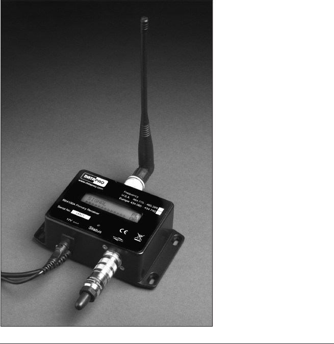
Primary Receiver
Part number Europe RX4200 – USA RX4100 – Japan RX4000
Dimensions (L × W × H) 139 × 98 × 44 mm (overall, including sockets and brackets)
Suitable antenna Standard: helical-coil (‘whip’ antenna), RX1011 (N America),
RX1010 (rest of the world)
Optional: unity-gain end-feed, RX1024 (N America), RX1023 (rest
of the world)
Frequency range Europe 434.065–434.740 MHz
N America 463.525–463.975 MHz
Japan 429.275–429.725 MHz
Rest of the world – Customized by Insight
Communications to PC USB
Operating temperature −20 to 70°C
Status display 2-line 16-character LCD + 1 red power LED
Power supply CH0070 power-supply unit
TM21 primary receiver:
helical-coil (‘whip’)antenna
attached on the upper side
of the unit, USB connection
cable on the lower left, and
an RS485 terminator in
place in the secondary-
receiver socket on the
lower right.
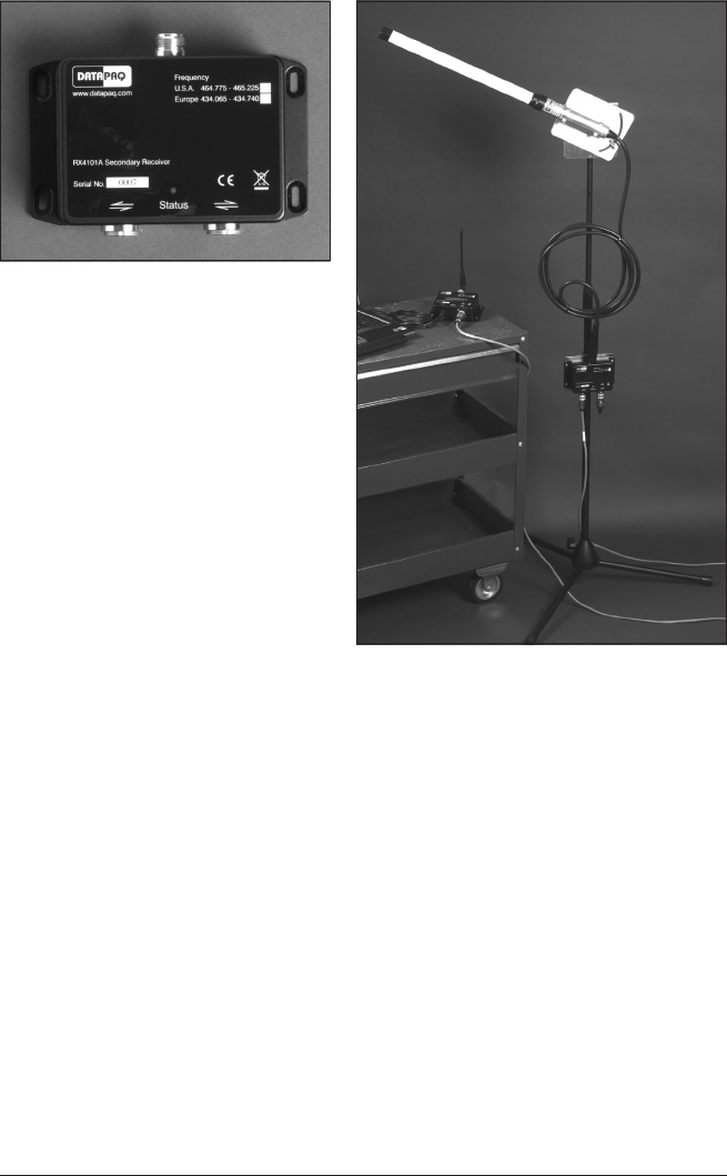
TM21 secondary receiver (above):
antenna socket is on upper side of the
unit, two secondary-receiver/terminator
sockets on the lower side (either of the
secondary-receiver sockets can be used
for the ‘in’ or for the ‘out’ cable).
Unity-gain end-feed antenna (right),
with secondary receiver mounted on the
antenna stand.
Secondary Receiver
Part number Europe RX4201 – USA RX4101 – Japan RX4001
Dimensions (L × W × H) 139 × 98 × 44 mm (overall, including sockets and brackets)
Suitable antenna Standard: unity-gain end-feed, RX1024 (N America), RX1023
(rest of the world)
Optional: helical-coil (‘whip’ antenna), RX1011 (N America),
RX1010 (rest of the world)
Frequency range Europe 434.065–434.740 MHz
N America 463.525–463.975 MHz
Japan 429.275–429.725 MHz
Rest of the world – Customized by Insight
Connection To primary receiver and other secondary receivers by RS485 cable
Maximum no. of secondary
receivers in one system
9 (depending on cable lengths)
Operating Temperature 0–70°C
Status display 1 green LED (on when powered up, flashes off when signal received)
Power supply Via primary receiver
TM21 R ADIO TEL E METRY Hardware Specifications 11

12 Hardware Specifications TM21 R ADIO TELE M ETRY

Setting Up the System
Basic setup of the TM21 system is similar for all applications, but special
considerations apply to its use in different industries, and these are also
described (p. 19).
The TM21 system permits simultaneous use of single or multiple loggers (see
p. 38) which transmit data to single or multiple radio receivers and transfer it to
the PC for recording and analysis by the system’s Insight software. The whole
system uses a single selectable radio frequency making use of on-air collision
avoidance to prevent interference between multiple transmitters monitoring a
single process.
As with all radio-frequency systems, the correct setup and siting of antennas is
critical to obtaining good reception.
The easiest sequence of operations to adopt when setting up a system for the
first time is typically as follows.
1. Set up the system’s receiver(s).
2. Establish Insight’s connection to the receiver(s) and initiate the search for a
clear frequency – and meanwhile . . .
3. Organize the logger, probes, thermal barrier and transmitter antenna.
4. Set or change the system’s radio frequency.
5. After this, you can go on to reset the logger(s) and start the profile run.
Setting Up Receivers
The TM21 system can be used with one or more radio receivers. The use of
multiple radio receivers is of value chiefly in applications where the secure
transmission and reception of radio-telemetry data requires receivers to be
sited at various widely separated points to pick up data from a logger moving
through the heat-treatment process.
A (single) primary receiver is attached to a PC running Insight software. If
multiple receivers are being used, additional secondary receivers are daisy-
chained to the primary receiver using an RS485 digital communications link.
Data received by Insight from multiple radio receivers is displayed and analyzed
just as if only a single receiver was in use. However, while a telemetry run is in
progress you can use Insight’s Real Time Tool dialog to obtain confirmation
in real time of the data being received by individual receivers (click on the
toolbar, or select View > Real Time Tool).
TM21 R ADIO TEL E METRY Setting Up the System 13
Setting Up a Single Receiver
1. Start by connecting the primary receiver’s USB cable to any available port on
the PC.
2. Plug an RS485 terminator into the secondary-receiver socket on the lower
side of the primary receiver.
3. Plug the receiver’s power-supply unit into the electricity supply, connect it to
the receiver, and switch on the power; the receiver’s red power LED comes
on. If the PC is also powered on, the receiver’s display (see p. 32) should show
‘
pc ok
’ to indicate a valid connection to the PC (Insight does not need to be
running); if there is no connection, or if the PC is powered down, ‘
pc xx
’ will
show.
4. Connect the antenna to the type-N coaxial socket on upper side of the
receiver (p. 10).
Ensure that all cables are arranged so that no strain is placed on them and that
there is no chance of them become disconnected during a profile run.
The receiver displays useful status information (p. 32), so it is helpful to place it
where the display can be readily seen. A variety of receiver and antenna
mounting kits is available from Datapaq, e.g. for fixed installation attached to
vertical surfaces.
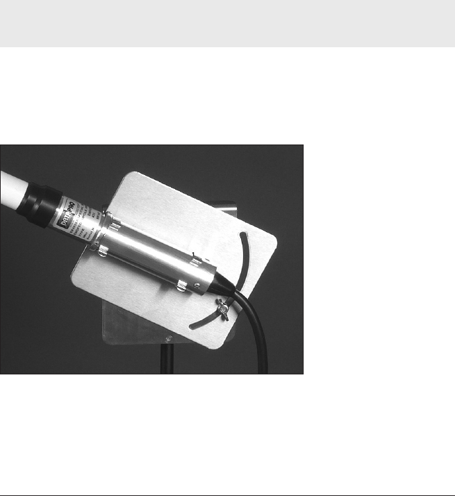
Correct fitting of unity-
gain end-feed antenna in
the rotating clamp of its
antenna stand.
Choice of antenna depends on the environment and on the strength of the
signal that can be received from the transmitter when it is within the process
being monitored. If a remote antenna (p. 11) is used (instead of the whip antenna
mounted directly on the receiver), it should be sited where the received signal
14 Setting Up the System TM21 R ADIO TE LE METRY
TM21 R ADIO TEL E METRY Setting Up the System 15
is strongest. This will usually be near the process chamber, but the location can
be optimized when the first profile run is carried out.
Cable length from receiver to antenna should not be greater than 20 m. If a
greater distance is required, it is advisable to incorporate a secondary receiver
attached by cable (see below) and attach the antenna to that, as this
arrangement will result in substantially better reception.
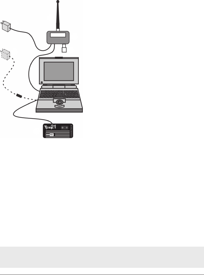
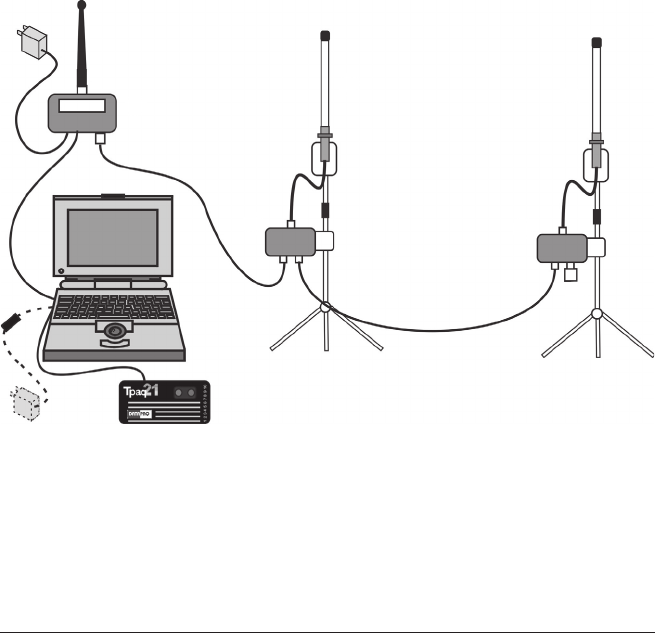
A
B
E
F
CD
The setup for a basic TM21 radio-telemetry
system with a single (primary) receiver (A); it
has a terminator (B) in place and a power-
supply unit (C) attached, and either a whip
antenna (D) or a remote antenna may be used.
The logger (E) is shown attached, for either
reset or download; optionally, the logger’s
charger (F) can be attached at this time. Such
a system may be suitable for, e.g., a batch
furnace where it is possible to monitor the
process from a position near the furnace.
Setting Up Multiple Receivers
1. Connect the primary receiver to the PC and to its antenna, as described
above – but do not connect a terminator to it.
2. Connect the primary receiver to its power-supply unit, but do not switch
on the power at this stage.
3. Choose a length of RS485 cable to run between the primary receiver and
the first secondary receiver. Take into account the layout of the process’s
oven/furnace/kiln in relation to a suitable location for the PC.
4. Connect one end of the cable to the socket on the lower side of the
primary receiver (p. 10), and the other end to one of the sockets on the lower
side of the secondary receiver.
Either of the sockets on the lower side of the secondary receiver can be used for the
‘in’ or for the ‘out’ cable.
16 Setting Up the System TM21 R ADIO TELE METRY
5. If further secondary receivers are used, fit RS485 connection cables to
connect the receivers together in a chain.
6. Fit a terminator to the free socket of last receiver in the chain.
7. Switch on power to the primary receiver. If the PC is powered on, the
primary receiver’s display should show ‘
pc ok
’ to indicate a valid connection
to the PC (Insight does not need to be running). The primary receiver’s
display should also register that each of the secondary receivers is connected
(see p. 32 for details of the display). If this is not the case, check all
connections and retry.
8. Connect an antenna to each receiver. Receiver antennas can either be
mounted on Datapaq height-adjustable stands (p. 11) or attached to a suitable
available surface. In either case, antennas should be located at least 1 m away
from any parallel conductive surface, e.g. metal-clad walls, steel posts, large
pipes. The location and orientation (vertical or horizontal) can be optimized
when the first profile run is carried out.
See above for choice of antennas and maximum length of antenna cables.
BB
A
CC
D
The setup for a TM21 radio-telemetry system with multiple receivers: primary receiver
(A) with whip antenna, and two secondary receivers (B) attached to unity-gain end-
feed antennas (C). Further secondary receivers may be added. The receiver at the end
of the chain is fitted with a terminator (D). Such a system may be suitable for, e.g., a
long continuous furnace.

TM21 R ADIO TEL E METRY Setting Up the System 17
Rarely, cables between receivers over 30 m long may be subject to disruption of
communication due to strong power surges (e.g. from lightning). This is rectified by
powering the receivers off and on; communications should then resume and Insight
will continue to log incoming data from that point onwards.
Establishing Connection with Insight
If Insight has not previously been set up for use with radio-telemetry receivers,
or if the setup has been changed, it is necessary to inform Insight of the
receivers attached and to confirm correct connection as follows.
1. Ensure that the primary receiver and its power-supply unit, secondary
receivers (if used), antennas and PC are connected as detailed above, and
that the primary receiver’s power is switched on.
2. In Insight, open the Radio Receivers dialog (click on the toolbar, or
select View > Radio Receivers).
3. In the dialog, click Detect to make Insight find the receivers, and to display
information about them.
The dialog then shows:
•The radio frequency currently in use.
•The serial number of each receiver connected.
Where two or more secondary receivers are connected, their sequence in the
dialog will not necessarily be the same as that in which they are connected. If
you wish, you may correct this: click on the image of a receiver and drag it to
the correct position.
If a receiver is not detected initially, due to a connection or power problem, a
warning is displayed on the icon for that receiver. If preferred, you may remove
that receiver’s icon from the display: right-click on the icon and select ‘Remove’.
Close the dialog to proceed.
Changing the System’s Frequency
The TM21 system is supplied with transmitter(s) and receiver(s) configured so
that they operate on the same radio frequency and can thus communicate. The
system’s operating frequency can however be changed, if thought necessary, by
using the Insight software:
1. Ensure all (primary and secondary) receivers are connected, as detailed above.
2. In Insight, open the Radio Receivers dialog (click on the toolbar, or
select View > Radio Receivers).

18 Setting Up the System TM21 R ADIO TE LE M ETRY
3. In the dialog, click ‘Radio Frequency Wizard’ and follow the on-screen
instructions.
You may select a specific frequency, or Insight will search for suitable
frequencies and rank them according to their susceptibility to external
interference.
When the logger is reset to receive fresh data (p. 29), it is automatically
instructed to use the same transmitter frequency as that set for the receivers. If
multiple loggers are used (see p. 38), they all use the same transmitter frequency.
If you already know the transmitter frequency you wish to use, you may select it as
part of resetting the logger (see p. 31).
Setting Up the Transmitter Antenna
Datapaq radio-transmitter antennas are designed specifically to resist the
temperature environment in which they operate and to match the operational
frequency of the transmitter. Failure to use the correct antenna may result in
degraded radio performance.
The orientation of the antenna (e.g. horizontal or vertical) is not important, but
the active portion of the antenna should be kept straight. Coiling the
antenna will reduce the transmitted power and degrade performance of the
system.
For antennas which incorporate a ground-plane base-plate (TX2020 and
similar), the active portion of the antenna is the flexible section that protrudes
from the base-plate.
•For antennas used in the furnace industry (typically the TX2040), the active
portion is the entire length of the antenna that is visible outside the closed
thermal barrier.
See also p. 19 for setup with furnace applications.
Whenever possible, position the transmitter antenna so that it is not close
to any metal surfaces which lie parallel with the plane of the antenna;
metal surfaces which run at right angles to the antenna do not present a problem.
If the connection-cable section of a transmitter antenna becomes damaged or
cut, the whole antenna should be replaced. It is not recommended to
re-terminate or repair the cable as special tools are required to ensure that a
good matched-impedance connection is achieved.
TM21 R ADIO TEL E METRY Specific Industries 19
Setup and Procedures in
Specific Industries
Each individual installation of the TM21 system will require a degree of
experimentation in establishing a good working setup. The following guidelines
are relevant to applications in specific industries.
Furnace Industry
If carrying out a temperature uniformity survey of a furnace using telemetry
with Insight Furnace Surveying software, see the Furnace Surveying
User Manual.
Transmitter Antenna Setup
Two types of antenna are available for furnace systems:
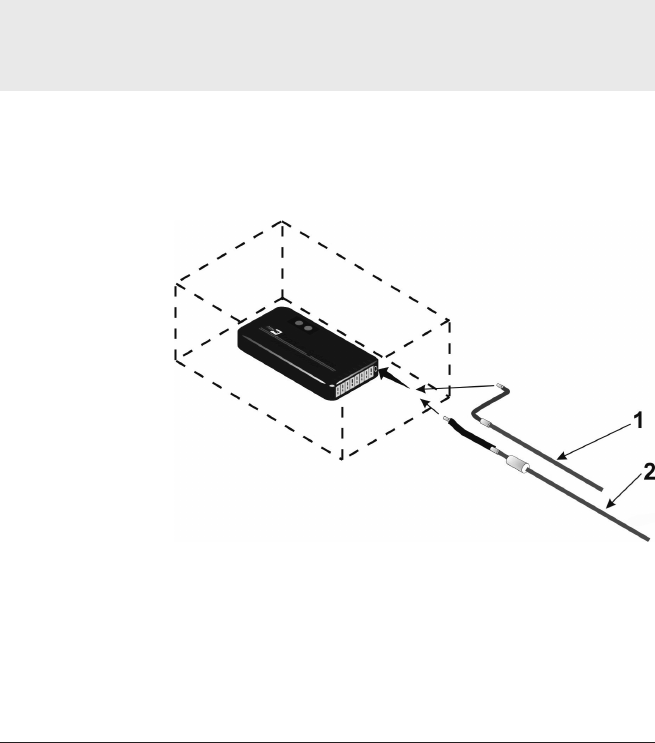
Attachment of antenna
types for use with
furnace systems. The
logger is shown within
a thermal barrier
(dashed outline).
1: TX2040A Furnace transmitter antenna for general applications.
2: TX2051A Furnace transmitter antenna for use only in low-height-quench thermal
barriers (TB4065, TB4072, TB4080, TB4086, TB4101, TB4120, TB4189, TB4196,
TB4239, TB4270).
20 Specific Industries TM21 R ADIO TELE METRY
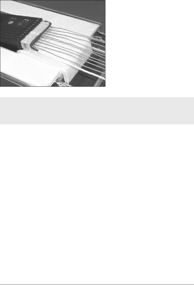
If using the TX2040A antenna, it is important to ensure that the antenna runs
across the thermocouple plugs of the logger before turning 90° and exiting
through the thermal barrier.
Tpaq21 logger with TX2040A
antenna correctly routed across
thermocouple plugs.
Ensure that the covering on the transmitter antenna remains intact and that no
part of it comes into contact with anything metallic, as this will seriously reduce
signal power.
Receiver Antenna Setup
Position the receiver antenna carefully to maximize reception. Tests have shown
that it is normally best for the receiver antenna to be in the same plane as the
transmitter antenna (usually horizontal), and the Datapaq antenna stand (p. 11)
allows the antenna to be oriented to achieve this.
If your furnace has glass viewing portals (usually in vacuum applications) or cable
exits, start by placing the antenna near these as they are good areas for the
signal to escape. If multiple receivers are used, it is usually effective to position
antennas at the entrance and exit of the furnace.
Ceramics Industry
Transmitter Antenna Setup
Two types of antenna are available, depending on whether it is to be plugged
into the front or rear of the thermal barrier.
TM21 R ADIO TEL E METRY Specific Industries 21
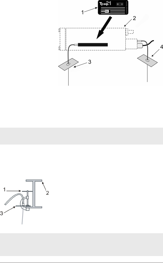
Antenna types for use with a
typical kiln thermal barrier.
1: Data logger. 2: Kiln thermal barrier.
3: Transmitter antenna TX2020A (1 m/3 ft), TX2022A (2 m/6 ft), TX2023A
(4 m/13 ft), for use when the front of the barrier faces the operator during setup.
4: Transmitter antenna TX2021A (1 m/3 ft), TX2024A (2 m/6 ft), TX2025A
(4 m/13 ft), for use when the rear of the barrier faces the operator during setup.
If using the antenna that plugs into the rear of the thermal barrier, ensure that the
barrier telemetry wire is plugged into the logger.
Both types of antenna have a ground-plane plate which must be securely
attached to the underside of the kiln car: use a G-clamp to fix to one of the
car’s I-beams, as close as possible to the sand-seal at the side of the car
(without fouling).
Attachment of transmitter antenna under a kiln car.
1: G-clamp.
2: Kiln car’s steel I-beam in section.
3: Ground-plane plate.
It is vital that:
•the ground-plane plate is clamped to the kiln car, and
•the antenna hangs vertically.
22 Specific Industries TM21 R ADIO TELE M ETRY
Receiver Antenna Setup
Typically, the primary receiver and PC will be located in the kiln office, well
away from the kiln, and connected to the first secondary receiver by cable
(see p. 15).
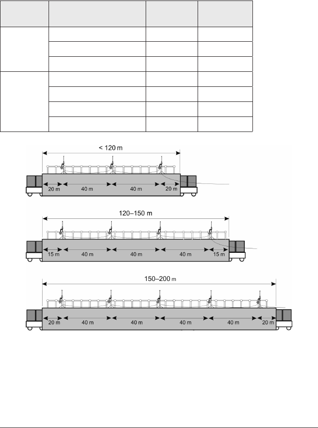
The recommended maximum spacing between secondary antennas for
brick-built and steel-clad kilns is as follows.
Kiln Length No. of
Antennas
Maximum
Spacing
Brick-built
kilns
< 120 m/394 ft 3 40 m/131 ft
120–150 m/394–492 ft 4 40 m/131 ft
150–200 m/492–656 ft 5 40 m/131 ft
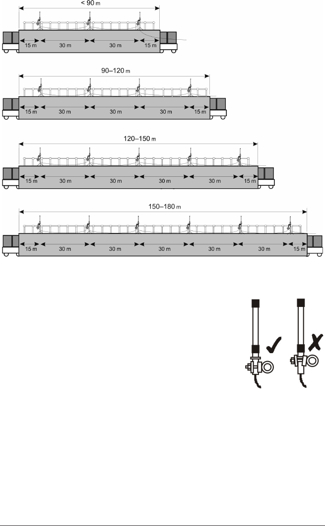
Steel-clad
kilns
< 90 m/295 ft 3 30 m/98 ft
90–120 m/295–394 ft 4 30 m/98 ft
120–150 m/394–492 ft 5 30 m/98 ft
150–180 m/492–591 ft 6 30 m/98 ft
Recommended numbers of antennas, and antenna spacing, for brick-built kilns of
different lengths.
TM21 R ADIO TEL E METRY Specific Industries 23
Recommended numbers of antennas, and antenna spacing, for steel-clad kilns of
different lengths.
Transmitter and receiver antennas should be in the same
plane (normally both vertical), with the receiver antennas
as close as possible to being directly above the
transmitter antenna, i.e. on the same side of the kiln.
Use the receiver antenna’s swivel clamp to fasten the
antenna to the kiln handrail. The adjacent diagram shows
the correct part of the antenna that may be clamped.
24 Specific Industries TM21 R ADIO TELE M ETRY
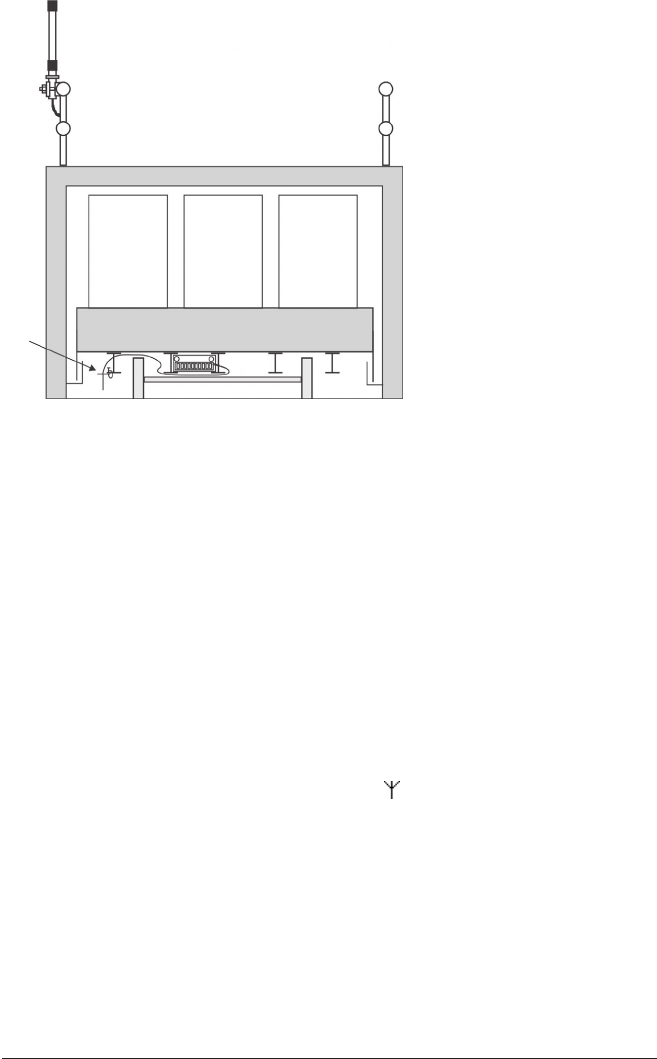
A
B
Vertical section through a kiln
and kiln car, showing a typical
installation of receiver
antennas (A, one shown) on
the kiln’s handrail, and
transmitter antenna (B)
below the kiln car. Receiver
and transmitter antennas
must be on the same side of
the kiln.
Oven Industry
In most coating applications the process time is relatively short (less than
30 mins), so, in general, monitoring of the process by radio-telemetry provides
little benefit. However, in batch or semi-batch applications, radio-telemetry can
allow efficient management of the process by monitoring temperature data in
real time without the need to have thermocouples trailing out of the oven. Cure
times can then be customized to the needs of specific products so that they are
removed from the oven at exactly the moment that cure has been identified.
Oven heating times are thus reduced, and productivity is improved.
Transmitter Antenna for General Batch Ovens
For oven applications the preferred transmitter antenna is the TX2040 which
plugs directly into the antenna socket (labelled ) of the Tpaq21 logger. Within
the process, the antenna should be positioned so that it does not touch either
the product or any of the oven’s metalwork. The antenna should be kept
straight if space allows (see also p. 19).
RotoPaq System (Rotomolding)
In rotomolding applications, in which the mold rotates during the process, it is
essential that the system is secured to the mold to minimize vibration of the
logger and of the transmitter antenna, and to prevent the system falling off.
Thus, if using the TB5000-RP or TB5016-RP thermal barriers, they should be
TM21 R ADIO TEL E METRY Specific Industries 25
secured using their mounting brackets. Ensure that the system is positioned so
that the antenna does not hit any part of the machine during rotation.
Choose the transmitter antenna as follows.
Thermal
Barrier
Transmitter
Antenna
TB5000-RP TX2040
TB5016-RP TX2091
TB4215 * TX2080
*
See Oven Tracker TB4215 RotoPaq Thermal Barrier User Guide supplied with the barrier.
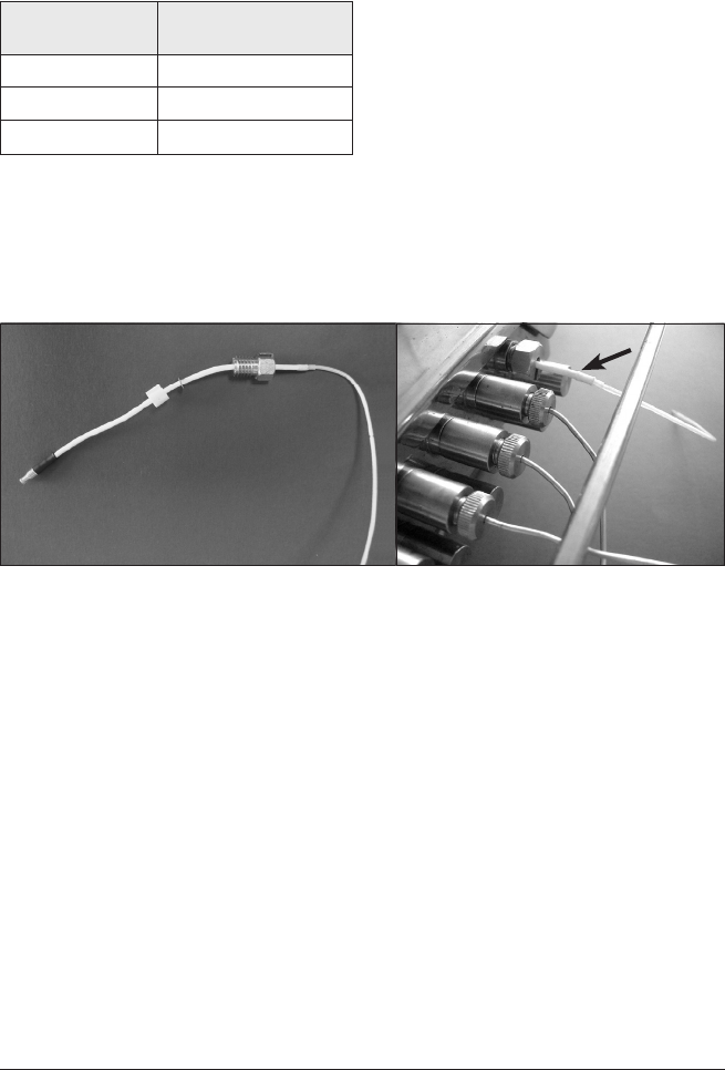
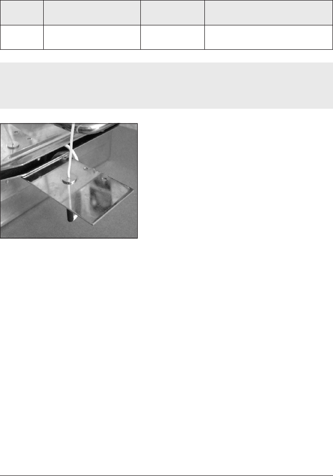
When using the waterproof TB5016-RP thermal barrier, the TX2091
antenna exits the barrier through the barrier’s available exit port. The aerial is
sealed in the port using a white probe seal (see photographs).
TX2091 antenna for use with TB5016-RP thermal barrier.
Left: antenna showing probe-seal and finger-screw used to create a seal in the barrier’s
face-plate. Right: antenna (arrowed) fitted in the face-plate.
Food Industry
Real-time monitoring by radio-telemetry in the food-processing industry is most
beneficial for batch or semi-batch process. An example of this is long-duration
cooks in Double D batch or rotating batch ovens followed by blast-chilling in a
separate unit: radio-telemetry allows the whole process to be monitored in real
time, which would not be possible with trailing thermocouples (hard-wired
telemetry) as the product and equipment are constantly rotating and need to be
transferred physically from cook to chill.
In many food processes, steam and water/brine are either used as part of the
cook/chill process or are produced during the process, and water and water
vapor can significantly inhibit radio-frequency transmission. Radio-telemetry is
26 Specific Industries TM21 R ADIO TEL E METRY
not feasible for any cooking where the system is submerged either in water
or oil.
Transmitter Antenna for MultiPaq21 Logger
Part
Number
Description Operating
Temperature
Typical Applications
TX2071A PTFE flexible coaxial
cable with reflector plate
Up to 265°C/
509°F
Conveyorized and batch oven
processes without submersion
Extreme care should be taken when handling, fitting or positioning the antenna,
as the performance of the whole system will deteriorate if it is fitted incorrectly.
Any damage to it could make the system inoperable.
Transmitting antenna screwed to
the thermal barrier’s splash guard.
When used with a non-submersible
thermal barrier (TB5009, TB5010,
TB5011), the antenna’s reflector plate is
screwed to the barrier’s splash guard.
With a submersible barrier (TB5815,
TB5816), a separate mounting bracket on
the side of the barrier is used.
The section of coaxial cable beyond the
reflector plate should be kept as
perpendicular to the plate as possible.
In installing the transmitter cable and
MultiPaq21 logger into the barrier, treat
the cable as if it is a thermocouple cable
(see the Food Tracker User Manual) and connect it to the logger’s antenna
socket next to probe no. 1 on the end of the logger. For submersible barriers,
feed the transmitter cable through the appropriate port in the barrier using a
white probe seal.
Receiver Antenna Set-up
The primary receiver is not IP rated against water ingress, so care must be
taken to protect it from moisture or other physical damage resulting either
from the process itself or from other shop-floor conditions including any regular
clean-down practices. Consequently it may be desirable to use a secondary
receiver and locate the PC and primary receiver well away from the hazards of
the food-processing environment. See p. 15 for details of setup.

TM21 R ADIO TEL E METRY Specific Industries 27
Electronics Assembly Industry
Reflow Soldering
The typical receiver arrangement for use with reflow ovens will consist of a
primary receiver only, normally equipped with whip antenna mounted on the
receiver. However, if the PC and receiver are not located directly adjacent to
the oven, the whip antenna should be replaced by a unity-gain end-feed antenna
which can then be located close enough to the oven to guarantee reception.
If a number of reflow ovens is to be monitored using telemetry, it can be
valuable to add a secondary receiver and antenna next to each oven. This
enables data to be received at a single PC from any one of the monitored ovens
without the need to repeatedly relocate the receiving antenna.
When the Reflow Tracker system is placed in the oven, the transmitter
antenna should be laid horizontally but held above the oven’s mesh belt by
placing it on PTFE blocks or similar. If the antenna is allowed to lay directly on
the belt, signal quality may be significantly reduced.
Other Processes
Radio-telemetry is generally not recommended for use in monitoring of wave-
solder processes as the minimum sample interval available is 0.5 s (when using
the Q18 logger), whereas the wave-solder process should be sampled every
0.05 s to ensure accuracy of measurement of contact time.
Radio-telemetry is not available for use in vapor-phase soldering processes.
Datapaq Service Department
If you cannot resolve your problem, please contact the Service Department at
Datapaq (see title page for contact details).

28 Specific Industries TM21 R ADIO TELE METRY

Running a Temperature
Profile
When both hardware and software for the TM21 system have been set up (p. 13
and p. 19), you can proceed to conduct a temperature-profile run.
By following the procedure described here you will use the Logger Reset and
Logger Download dialogs to run a temperature profile using radio telemetry.
Thus, as the logger gathers data from the product inside the process, this is
transmitted directly to the PC by radio transmitter/receiver. The temperature
profile can be watched developing as it happens, i.e. in real time.
After the run is completed, the data received by telemetry can be saved as a
new file (a ‘paqfile’). However, as data is also stored internally in the logger
during the run, it may be preferable instead to download the data from logger
to PC after the run is finished and to save that as the final paqfile (p. 36). This
means there is less chance of the paqfile having missing data points due to losses
in transmission.
The TM21 system permits use of multiple loggers, so data can then be
gathered from a greater number of thermocouple channels than can be achieved
with a single logger (see p. 38).
Resetting the Logger and Starting the Run
Ensure first that:
•The (primary) receiver is connected to the PC via a USB port, and to its
power supply (see p. 15).
•If Insight has not previously been set up with radio-telemetry receivers, or if
the setup has been changed, open the Radio Receivers dialog to inform
Insight of the receivers attached, and to provide confirmation of correct
connection (see p. 17).
The data logger needs to be reset, as follows, before it can receive fresh data.
(If multiple loggers are used for the run, this process is repeated for each
logger.)
TM21 R ADIO TEL E METRY Running a Temperature Profile 29

The procedure described here uses the Insight software’s Logger Reset dialog. If you
are less sure of the process, and if using a single logger for a profile run, you
can instead use the Logger Reset Wizard to guide you, step-by-step, through this
stage of running a profile: click on the Insight toolbar, or select Tools > Wizards
from the menu.
If carrying out a temperature uniformity survey of a furnace using Insight
Furnace Surveying software with single or multiple loggers and single or multiple
radio receivers, temperature profiles should be run using the software’s
Temperature Uniformity Survey Wizard, and not as described below.
Depending on the model of your logger, it may not necessary to go through the
reset procedure if the previous reset options are to be re-used: see your logger’s
User Manual.
Ensure that your logger has cooled sufficiently from the previous run. Some models
of logger cannot be reset if they are too hot: see your logger’s User Manual.
Any data stored in the logger but not yet analyzed must be downloaded before
proceeding, as resetting the logger will permanently erase all data
stored in it.
If the system’s radio frequency needs to be changed, this can be done either
before the logger is reset, by using the Radio Frequency Wizard (see p. 17), or during
the reset (see below).
1. If the logger is fitted with a rechargeable NiMH battery, ensure it is
adequately charged. The logger may be on charge during the reset. See your
hardware manual for the charging process.
2. Use the communications lead supplied to connect the logger to a free
USB or COM (serial) port on the PC (if using multiple loggers, you must
use USB).
To minimize communications problems: a) connect the lead first to the PC and then
to the logger; b) if using USB, always use the same USB port – the one which was
first used to set up communications.
The red LED on the logger should flash five times to confirm that the
connection between the communications lead and the logger has been made.
3. Open the Logger Reset dialog (click on the Insight toolbar, or press
function key F2, or select Logger > Reset from the menu bar) and specify
the use of radio telemetry.
Using radio telemetry increases the logger’s power consumption and will thus
tend to shorten the logger battery’s operation time. This effect can be
minimized by choosing appropriate reset options, as follows:
•Sample Interval Longer sample intervals reduce power consumption.
30 Running a Temperature Profile TM21 R ADIO TELE METRY

•Probes Selected Deselect unused probe channels to prevent
transmission of redundant data.
•Transmissions (click ‘Advanced Telemetry’ button) The system’s
transmitter can make multiple transmissions (interleaving), i.e. it sends
each reading a number of times in order to increase reception quality.
This can overcome momentary interference such as that caused by the
switching of large electrical loads, but it consumes more power. Typically,
three transmissions is a good compromise for most industrial processes.
Using interleaving increases the minimum sample interval which can be
achieved (see p. 9).
Select other reset options, including trigger mode, and note whether the
memory and battery status are adequate for your run (the display of battery
status is invalid for lithium batteries).
If required, the transmitter’s radio frequency can be set here (click the ‘Advanced
Telemetry’ button) – though in normal use it is best to let Insight set this
automatically, to match the receiver frequency (which is set by using the Radio
Frequency Wizard before the logger is reset, see p. 17). For more details of this and
other reset options, see Insight’s Help system and select Menu Functions >
Logger > Reset.
4. After clicking OK, the logger is reset and a message box confirms the
sample interval and trigger mode you have set.
5. Disconnect the communications lead from the logger.
6. The logger’s red and green status LEDs then briefly flash alternately to
confirm logger reset; click OK.
7. The Select Process dialog then appears in order that you may choose a
process file to apply to the results. If the process file and its components
have been given names, these are shown when the process file is selected in
the list. Click ‘No Process’ if you do not want to apply a process file.
(A process file allows you to see the temperature profile in relation to the
oven zones as the profile appears on screen during the run. See the Insight
software for an introduction to process files: press function key F1, or select
Help > Contents from the menu bar, and click the section ‘Process Files:
Oven, Recipe, Product’.)
8. If multiple loggers are used for the run, the process above is then
repeated for each logger until all are reset.
9. Plug the thermocouples into the logger’s numbered sockets. If you are
using a process file, ensure that the probe/socket numbers on the logger
correspond to those used to define probe numbers and locations in that file.
10. Ensure the sealing surfaces of the thermal barrier are clean and
TM21 R ADIO TEL E METRY Running a Temperature Profile 31
32 Running a Temperature Profile TM21 R ADIO TE LE M ETRY
undamaged. Good barrier seals, including those between the barrier and the
thermocouple cables, are essential if the logger is to be protected.
11. If the trigger mode is Start Button, press and hold the logger’s start button
for about 1 second until the green LED starts to flash at the sample interval.
12. Put the logger into the barrier, seal it, and place the logger–barrier assembly
into your process together with your instrumented product or test-piece.
For guidance specific to your application, see p. 19 and your system’s User Manual.
You may specify that a password is required when an attempt is made to close
Insight while a real-time telemetry run is in progress:
select Tools > Options > General.
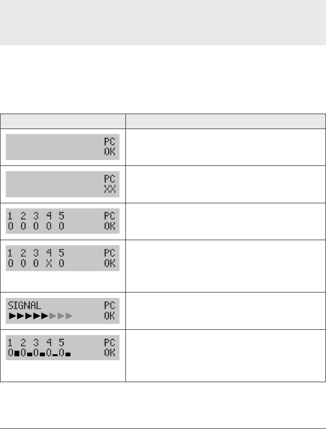
Receiver Status
As soon as transmitted data is being received by the primary receiver, its display
records the status. Details of the receiver displays are shown below.
Display Meaning
Good USB connection to powered-up PC.
No USB connection, or PC not powered up.
Primary receiver (1) and four secondary receivers (2–5)
are connected, and communication is established.
One secondary receiver has become disconnected or
communication is not fully established. NB The numbering
of secondary receivers in the display is arbitrary and does not
reflect their connection sequence, though the numbering will
be constant during each powered-up session.
Data-packet being received by primary receiver.
After the
signal
display when the primary receiver
receives a data-packet, this display appears until the next
data-packet is received: the height of the bar shown
briefly adjacent to each receiver’s number represents the
signal strength recorded by it.

Display Meaning
Red LED – primary receiver LED on when powered up.
Green LED – secondary receiver LED on when powered up. Flashes off when signal is being
received.
Real-time Data Collection
Once new data starts to be received, it is displayed in Insight’s Graph and
Analysis Windows, scrolling in real time as new data arrives. You may change
the way the data is displayed with the Axes tab of the Graph Options dialog
(from the right-click menu, or from the main menu select View > Graph
Options): under Telemetry, specify how much of the recently received data is
displayed, and whether you wish to see only a certain temperature (y-axis)
range, centered on the latest data.
You may zoom the display as when viewing a paqfile, except that:
•Double-clicking on the graph (or selecting Real Time Zoom from the View
menu or right-click menu) shows only the most recently received portion of
the data on the scrolling graph (see above).
•Saved zoom modes are not available.
If the y-axis is not set to be centered (see above), the default y-axis zoom
changes as more data is received, in order to accommodate all received data.
To move the graph across the viewing area, hold Shift and drag the
mouse pointer.
You may overlay one or more tolerance/ideal curves or other paqfiles on
the graph to compare with the data as it is being received (select View >
Overlay).
If you wish to open another paqfile and view it in a separate tab while the logger is
in listen mode, i.e. while data is being received and viewed in real time, you must
first stop real time mode (see p. 35). You may instead, however, open the other
paqfile as an overlay while still in real time mode, as above.
You may adjust the oven/furnace/kiln start position while a real-time run is
in progress (select Process > Adjust Oven/Furnace/Kiln Start, or use the right-
click menu; see also Insight’s Help system or your logger’s User Manual).
Calculations shown in the Analysis Window for the chosen data analysis
mode update continuously as new data is received. As for non-real-time runs,
calculations are performed only on the currently zoomed area shown on the
graph. However, if the graph is scrolling and showing just the most recently
TM21 R ADIO TEL E METRY Running a Temperature Profile 33
received portion of the results, the analysis calculations will be performed as if
on the full zoom view.
Real Time Tool
While a radio-telemetry run is in progress, you may use the Real Time Tool
dialog to check the integrity of data-packets as they are received, as well as the
status of the logger(s) and the receiver(s) (click on the toolbar, or select
View > Real Time Tool).
The dialog shows:
•The status of receivers and loggers in use.
•Real-time confirmation of data being transmitted and received, and its
quality.
Information is transmitted from the logger as data-packets (i.e. sets of data
from all of the logger’s probes at a given instant, determined by the sample
interval specified). The TM21 radio-telemetry system can transmit a given data-
packet multiple times, interleaving this with other data-packets, thus greatly
increasing the security of data transmission (see also p. 31).
Click Contract to remove the receivers from the dialog’s display, and to
reduce logger information to that which concerns packet transmission/
reception. Expand restores the full display.
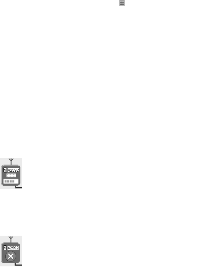
Receivers
The dialog shows icons representing all of the attached receivers, each with
their receiver number and serial number. The primary receiver is shown as
receiver number 1.
When each receiver receives a data-packet, the signal-strength
window within its icon (see left) shows a green bar which lengthens
in proportion to the signal strength while the data-packet is being
received. A small vertical black bar in the signal-strength window
shows the strength of the previous signal received. If no further data
is received, the black bar moves to the left.
Where two or more secondary receivers are connected, their sequence in the
dialog will not necessarily be the same as that in which they are connected. If
you wish, you may correct this: click on the image of a receiver and drag it to
the correct position.
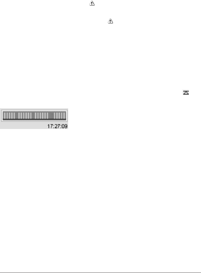
If a receiver is not detected initially, due to a connection or power
problem, a warning is displayed on the icon for that receiver (see
left) until Insight detects it. If preferred, you may remove that
receiver’s icon from the display: right-click on the icon and select
‘Remove’.
34 Running a Temperature Profile TM21 R ADIO TE LE METRY
TM21 R ADIO TEL E METRY Running a Temperature Profile 35
Loggers
The loggers section of the dialog shows a summary of status and data
transmission for each logger in use.
Logger ID The logger’s serial number – highlighted in blue for the logger
which sent the last data-packet to be received.
Battery Percentage of full charge. For lithium batteries a figure is not shown,
but the display will show a warning when the battery charge is low.
Temperature Temperature of the logger’s thermocouple cold junction
(logger’s internal temperature). A warning indicates that the maximum
permitted value has been exceeded.
Frequency The radio frequency currently being used by the system (see
above).
Packet ID Identity number of last data-packet received.
Next Data Due A countdown, in steps of 1 s, to the time when the next
data-packet is expected (according to the sample interval set).
Data Received The number of valid data-packets received, as a percentage
of the total number of data-packets transmitted so far. The reset button
next to the percentage figure forces this calculation to restart.
Last Transmission The scrolling display shows
groups of data-packets as they are received.
Green packets indicate good data, red packets
show invalid data (e.g. with a checksum error).
Larger-than-usual gaps between the groups of packets indicate transmissions not
received. The time of receipt of the last transmission is shown below the display.
You may choose to have the PC beep as each valid data-packet is received.
Ending Real-time Data Collection
You may wish to end data-collection when the logger is removed from the
oven/furnace/kiln – or, by selecting Logger > Stop Real Time Mode, you may
end or pause it while a telemetry run is still in progress. Data then continues to
be collected by the logger, but it is no longer received in real time by Insight
(download from the logger after the run is finished to retrieve the full data).
The graphical and numerical data received up to that point remain on screen,
available for viewing and analysis, and can be saved as a paqfile.
While the logger is still transmitting, you may resume the collection of
transmitted data (select Logger > Logger Listen Mode). After the first few
data-packets have been received, the data starts to be displayed in the Graph
and Analysis Windows. This second bout (and any subsequent bouts) of data-
collection can also be ended and saved as a separate paqfile, as above.

36 Running a Temperature Profile TM21 R ADIO TELE M ETRY
If Autosave is enabled (select Tools > Options > General), the data being
gathered is automatically saved periodically during a telemetry run. If the PC system
fails during the run, the last-autosaved version of the data is displayed automatically
when Insight is next run, and you may then choose to save it as a paqfile.
To stop a real-time run being ended accidentally, you may specify that a password
be entered when an attempt is made to close Insight while a run is in progress:
select Tools > Options > General.
Although the full data from the profile run should already have been received by
Insight, and can thus be saved as described above, it is best practice also to
download the data from the logger (see below) and to retain that version as well as
the transmitted version of data.
When the run is complete, go on to remove the logger from the furnace.
Recovering the Logger and
Downloading Data
Recover the system from the oven/furnace/kiln as soon as the run is over.
WARNING
The logger will be hot. Use protective gloves.
Failure to remove the logger from the hot thermal barrier could damage the logger.
See your system’s User Manual.
1. Open the thermal barrier. Placing it on a cold surface will increase its rate
of cooling. (An additional thermal barrier should be purchased if insufficient
time is available to allow it to cool between test runs.)
2. Remove the logger from its thermal barrier.
3. If data acquisition has to be stopped manually, press and hold the stop
button until the red and green status LEDs are on simultaneously. A red
LED flashing every 5 s indicates data stored in the logger but not yet
downloaded to the PC.
4. Use the communications lead supplied to connect the logger to a free
USB or COM (serial) port on the PC (if using multiple loggers, you must
use USB).
To minimize communications problems: a) connect the lead first to the PC and then
to the logger; b) if using USB, always use the same USB port – the one which was
first used to set up communications.

TM21 R ADIO TEL E METRY Running a Temperature Profile 37
The red LED on the logger should flash five times to confirm that the
connection between the communications lead and the logger has been made.
5. Open the Logger Download dialog (click on the toolbar, or press function
key F3, or select Logger > Download from the menu bar) and wait while the
data is downloaded to the PC.
If using a single logger for a profile run, you can also download the logger using the
Logger Download Wizard (click or select Tools > Wizards).
You can set run alarms to be triggered during a logger download, to warn you of
incomplete data recorded during the profile run (from the menu bar, select Tools >
Options > Run Alarms).
If you see the message
Logger stopped due to going over temperature
the data logger’s maximum-permitted internal temperature has been exceeded, and
it may have suffered damage. The reason for the excessive temperature – which
may be the result of process operational problems or the use of an inappropriate
thermal barrier – must be resolved before further profile runs take place; contact
Datapaq for advice.
A warning message will also be shown if the logger has stopped recording data due
to a discharged battery.
In both cases, data recorded up to that point will have been preserved.
6. The Select Process dialog then appears in order that you may choose a
process file to apply to the results. If the process file and its components
have been given names, these are shown when the process file is selected.
Click ‘No Process’ if you do not want to apply a process file.
If you will normally not wish to apply a process file to the results, you can opt not to
have the Select Process dialog displayed immediately after a download (from the
menu bar, select Tools > Options > Process File); a process file may then still be
applied subsequently.
7. The newly downloaded data then appears on screen numerically and
graphically. Save the data as a paqfile.
The data from your profile run can now be displayed, printed and analyzed as
you wish (see Insight’s Help system).
If you have not applied a process file, or if the process file you applied did not
specify that the oven/furnace/kiln start position be adjusted, you may want
to adjust that start position now (select Process > Adjust Oven/Furnace/Kiln
38 Running a Temperature Profile TM21 R ADIO TELE M ETRY
Start). This can be valuable as it permits different paqfiles, i.e. data from
different temperature profile runs, to be compared with each other.
Information about the logger and the data-collection process for the paqfile
(including time/date, trigger mode and maximum internal logger temperature)
can be seen in the Paqfile Properties dialog (select File > Properties, or graph
right-click menu).
Using Multiple Loggers
The use of multiple loggers permits data to be gathered from a greater
number of thermocouple channels than can be achieved with a single logger.
Multiple loggers used with radio-telemetry may be housed in the same or in
separate thermal barriers.
Data from multiple loggers used in a single profile run is displayed all together in
a single window by Insight. The data can be stored in a single paqfile, or as
individual paqfiles, each containing data from one of the loggers.
Insight’s floating logger toolbar controls the display of data from each logger,
and allows data from any one logger to be saved as a separate paqfile. The
logger number – shown in the logger toolbar – allows duplicate probe numbers
from the multiple loggers to be separately identified in the Analysis Window and
probe toolbar, and in the probe key to the right of the graph.
The sort order of the duplicate probe numbers in the Analysis Window is
changed by the and buttons.
While a telemetry run is in progress, the Real Time Tool dialog gives a summary
of status and data transmission for each logger in use (click on the toolbar,
or select View > Real Time Tool; see also Insight’s Help system).
When using the Furnace Surveying module of Insight, the use of multiple loggers
is handled entirely by the Temperature Uniformity Survey Wizard which is available
within that module.

TM21 R ADIO TEL E METRY Running a Temperature Profile 39

www.datapaq.comwww.datapaq.com
Europe & Asia
Datapaq Ltd
160 Cowley Road
Cambridge CB4 0GU
UK
Tel: +44-(0)1223-423141
Fax: +44-(0)1223-423306
sales@datapaq.co.uk
North & South America
Datapaq Inc.
187 Ballardvale Street
Wilmington
MA 01887
USA
Tel: +1-978-988 9000
Fax: +1-978-988 0666
sales@datapaq.com
Germany
Datapaq GmbH
Valdorfer Straße 100
D-32602 Vlotho
Germany
Tel: +49-5733-91070
Fax: +49-5733-18432
sales@datapaq.de
China
Datapaq Ltd
3rd Floor, Lane 280-6
Linhong Road
Shanghai 200335
China
Tel: +86(0)21-6128-6200
Fax: +86(0)21-6128-6221
Fax: +86(0)21-6128-6222
sales@datapaq.com.cn